EP3932809B1 - Luftschleiersysteme und -verfahren für innenkabinen von fahrzeugen - Google Patents
Luftschleiersysteme und -verfahren für innenkabinen von fahrzeugen Download PDFInfo
- Publication number
- EP3932809B1 EP3932809B1 EP21183440.3A EP21183440A EP3932809B1 EP 3932809 B1 EP3932809 B1 EP 3932809B1 EP 21183440 A EP21183440 A EP 21183440A EP 3932809 B1 EP3932809 B1 EP 3932809B1
- Authority
- EP
- European Patent Office
- Prior art keywords
- seats
- air
- air curtain
- vents
- vehicle
- Prior art date
- Legal status (The legal status is an assumption and is not a legal conclusion. Google has not performed a legal analysis and makes no representation as to the accuracy of the status listed.)
- Active
Links
Images



Classifications
-
- B—PERFORMING OPERATIONS; TRANSPORTING
- B64—AIRCRAFT; AVIATION; COSMONAUTICS
- B64D—EQUIPMENT FOR FITTING IN OR TO AIRCRAFT; FLIGHT SUITS; PARACHUTES; ARRANGEMENT OR MOUNTING OF POWER PLANTS OR PROPULSION TRANSMISSIONS IN AIRCRAFT
- B64D13/00—Arrangements or adaptations of air-treatment apparatus for aircraft crew or passengers, or freight space
-
- B—PERFORMING OPERATIONS; TRANSPORTING
- B60—VEHICLES IN GENERAL
- B60Q—ARRANGEMENT OF SIGNALLING OR LIGHTING DEVICES, THE MOUNTING OR SUPPORTING THEREOF OR CIRCUITS THEREFOR, FOR VEHICLES IN GENERAL
- B60Q3/00—Arrangement of lighting devices for vehicle interiors; Lighting devices specially adapted for vehicle interiors
- B60Q3/40—Arrangement of lighting devices for vehicle interiors; Lighting devices specially adapted for vehicle interiors specially adapted for specific vehicle types
- B60Q3/41—Arrangement of lighting devices for vehicle interiors; Lighting devices specially adapted for vehicle interiors specially adapted for specific vehicle types for mass transit vehicles, e.g. buses
- B60Q3/44—Spotlighting, e.g. reading lamps
-
- B—PERFORMING OPERATIONS; TRANSPORTING
- B64—AIRCRAFT; AVIATION; COSMONAUTICS
- B64D—EQUIPMENT FOR FITTING IN OR TO AIRCRAFT; FLIGHT SUITS; PARACHUTES; ARRANGEMENT OR MOUNTING OF POWER PLANTS OR PROPULSION TRANSMISSIONS IN AIRCRAFT
- B64D11/00—Passenger or crew accommodation; Flight-deck installations not otherwise provided for
- B64D11/06—Arrangements of seats, or adaptations or details specially adapted for aircraft seats
-
- B—PERFORMING OPERATIONS; TRANSPORTING
- B64—AIRCRAFT; AVIATION; COSMONAUTICS
- B64D—EQUIPMENT FOR FITTING IN OR TO AIRCRAFT; FLIGHT SUITS; PARACHUTES; ARRANGEMENT OR MOUNTING OF POWER PLANTS OR PROPULSION TRANSMISSIONS IN AIRCRAFT
- B64D11/00—Passenger or crew accommodation; Flight-deck installations not otherwise provided for
- B64D11/06—Arrangements of seats, or adaptations or details specially adapted for aircraft seats
- B64D11/0606—Arrangements of seats, or adaptations or details specially adapted for aircraft seats with privacy shells, screens, separators or the like
-
- F—MECHANICAL ENGINEERING; LIGHTING; HEATING; WEAPONS; BLASTING
- F24—HEATING; RANGES; VENTILATING
- F24F—AIR-CONDITIONING; AIR-HUMIDIFICATION; VENTILATION; USE OF AIR CURRENTS FOR SCREENING
- F24F9/00—Use of air currents for screening, e.g. air curtains
Definitions
- Embodiments of the present disclosure generally relate to air curtain systems and methods, such as may be used within internal cabins of vehicles. Specifically, the present disclosure relates to a vehicle comprising an air curtain system and to an air curtain method for a vehicle.
- HEPA filters in the air conditioning system that are able to entrap microbes and pathogens.
- the HEPA filters receive and clean air exiting the cabin or about to enter the cabin.
- HEPA filters and frequent cleaning of the cabin between flights are some methods to ensure the health of the passengers and crew onboard the aircraft. Further, certain passengers may prefer to wear masks within an internal cabin of a vehicle in order to reduce the risk of spreading pathogens.
- GB 2 579 547 A describes, according to its abstract, a vehicle system that has a vehicle cabin with an air flow system and a seat that can be moved to plurality of positions.
- the air flow system includes a plurality of air vents, an air flow apparatus that can selectively direct an air flow through each of the plurality of air vents, and a controller that can receive a signal indicative that a user is seated in the seat from an occupancy sensor and a signal indicative of the position of the seat from the position sensors.
- the controller provides output for providing a control signal to the air flow apparatus to control which of the plurality of air vents to direct the air flow through based on the occupancy signal and in dependence on the seat signal.
- the cabin may be defined by an upper cabin surface and a lower cabin surface with at least one of the air vents located in the upper surface and one in the lower surface.
- JP 6 669845 B1 states, according to its abstract, an infection control device which is mounted on a vehicle in which a plurality of seats are arranged side by side in the front-rear direction and the left-right direction to suppress infection among a plurality of passengers, wherein the device comprises an intake port for sucking air from the rear.
- the device further has an air purifying mechanism that purifies the air taken in from the intake port to make it clean air, and an air outlet that blows out clean air forward.
- Air barrier forming units are provided at each of the side ends of the backrests of the plurality of seats such that the air barrier units face each other in the front-rear direction and clean air blown out from the air outlet of the air barrier forming unit at the rear is supplied to the intake port of the air barrier forming unit at the front.
- US 2019/077215 A1 provides, according to its abstract, a personalized thermal comfort system which includes an air registration system, configured to establish discrete air curtains around individual seats in a vehicle passenger cabin, and an HVAC system.
- the HVAC system functions to condition air flowing in the discrete air curtains.
- the HVAC system includes a controller configured to allow a seat occupant to individually control the conditioning of air in the air curtain associated with the occupied seat.
- US 2014/363333 A1 is directed, according to its abstract, at methods, systems, and apparatuses to produce a predictably shaped and minimally intrusive air barrier that may comprise an airborne disinfectant, to divert and or render harmless and to divers and negate close proximity airborne pathogens, such as influenza and severe acute respiratory syndrome, etc., and other airborne particulates transferred from an infected person towards the face of an unfortunate recipient at normal conversational distances apart from each other.
- an airborne disinfectant to divert and or render harmless and to divers and negate close proximity airborne pathogens, such as influenza and severe acute respiratory syndrome, etc., and other airborne particulates transferred from an infected person towards the face of an unfortunate recipient at normal conversational distances apart from each other.
- the air curtain system is further configured to provide one or more air curtains between adjacent seats of one or both of the first group or the second group.
- the air curtain system includes one or more outflow vents that output the one or more air curtains.
- the one or more outflow vents may be disposed above the seats.
- the one or more outflow vents may be disposed within the seats.
- the air curtain system further includes an airflow generator that generates airflow that is received by the one or more outflow vents.
- the airflow generator may be contained within one or more of the seats.
- the air curtain system further includes one or more return vents that receive the one or more air curtains.
- the one or more return vents may be disposed below the seats.
- the one or more return vents may be disposed within the seats.
- the air curtain system further includes a control unit that is configured to control positions of the one or more outflow vents in response to positions of the seats.
- the air curtain method further comprises disposing one or more outflow vents above the seats.
- the air curtain method further comprises disposing one or more outflow vents within the seats.
- Said providing may further comprise generating, by an airflow generator, airflow that is received by the one or more outflow vents.
- the air curtain method may further comprise containing the airflow generator within one or more of the seats.
- the air curtain method may further comprise receiving, by one or more return vents of the air curtain system, the one or more air curtains.
- the air curtain method may further comprise disposing the one or more return vents below the seats.
- the air curtain method may further comprise disposing the one or more return vents within the seats.
- the air curtain method may further comprise controlling, by a control unit, positions of the one or more outflow vents in response to positions of the seats.
- the air curtain method may further comprise emitting, by one or more light emitting devices, light along at least a portion of the one or more air curtains to indicate presence of the one or more air curtains.
- Certain embodiments of the present disclosure provide an air curtain system and method within an internal cabin of a vehicle.
- the air curtain system is configured to generate an air curtain between seats and/or rows within the internal cabin to provide a more controlled airspace.
- FIG. 1 illustrates a schematic block diagram of an air curtain system 100 within an internal cabin 102 of a vehicle 104, according to an embodiment of the present disclosure.
- the air curtain system 100 includes an airflow generator 106 that is configured to generate airflow that is directed through one or more outflow vents 108.
- the outflow vents 108 include one or more nozzles, or other such outlets that are configured to direct the airflow from the airflow generator 106 as an air curtain 110 between rows 114 of seats 112 and optionally between seats 112.
- the air curtain 110 that is output through the outflow vents 108 passes between the rows 114 and optionally between the seats 112 J and is received by one or more return vents 116 (including one or more nozzles, or other such intakes), which channel the resulting airflow back to the airflow generator 106 via one or more conduits 118, such as ducts.
- the nozzles may be sized and shaped to cover a single seat 112 or a row 114 of seats 112.
- an outflow vent 108 in the form of an elongated nozzle that extends over a group of seats 112 may be used.
- an outflow vent 108 having a nozzle that extends over only one seat 112 may be used.
- the airflow generator 106 may include one or more of a blower, fan, vacuum generator, and/or the like.
- the airflow generator 106 is secured within the internal cabin 102.
- the airflow generator 106 may be disposed above a ceiling 120, behind a wall, within a compartment, and/or the like.
- the airflow generator 106 may be disposed on or within one or more of the seats 112, such as above and/or behind a headrest, within a support base, and/or the like.
- the airflow generator 106 may be or include an air intake within one or more passenger service units (PSUs) above the seats 112.
- PSUs passenger service units
- the main air supply system of the vehicle 104 may include the airflow generator 106.
- the airflow generator 106 may be independent of a main air supply system of the vehicle 104.
- an airflow generator 106 may be integrated into one or more of the seats 112.
- each seat 112 may include an airflow generator 106.
- the airflow generator 106 may draw air from within the internal cabin 102.
- the airflow generator 106 may draw air from an area by or surrounding a seated passenger.
- the airflow generator 106 may include one or more air filters that filter the airflow before the passing out of the outflow vents 108.
- the airflow generator 106 may draw in air from both one or more of the PSUs and from the seated passenger area to increase air flow.
- the airflow generator 106 includes a fan that draws air from one or more of the PSUs and/or the seated passenger area.
- air intakes proximate to and/or from the seated passenger area may be located to increase the space of the protected area and/or locate the air curtain 110 as desired.
- the outflow vents 108 may be secured in the ceiling 120 above the seats 112. As another example, the outflow vents 108 may be disposed on one or more of the seats 112. For example, one or more of the outflow vents 108 may be disposed on or proximate to portions of a head rest, such as lateral portions of the head rest. As another example, the outflow vents 108 may be within one or more PSUs.
- the outflow vents 108 are sized and shaped to provide a desired size and/or shape of the air curtain 110.
- the outflow vents 108 may include a gasper having one or more slits that are configured to shape the air curtain 110.
- the return vents 116 may be sized and shaped the same or similar as the outflow vents 116 and are configured to receive and catch the air curtain 110 output by the outflow vents 108.
- the return vents 116 may be disposed below the seats 112, such as on and/or within a floor 122 that supports the seats 112. As another example, the returns vents 116 may be on lower portions of the seats 112, such as underneath a seat pan.
- the conduit(s) 118 may be routed underneath the floor 122, behind walls, and to the airflow generator 106. The return vents 116 facilitate returning the airflow of the air curtain 110 back to the airflow generator 106.
- the air curtain system 100 may not include the return vents 116.
- the outflow vents 108 (such as air outlets) and the returns vents 116 (such as air intakes) may be located relative to the seats 112 to adjust in response to the seats being upright or reclined.
- the outflow vents 108 and return vents 116 may be coupled to one or more actuators 109 and 117, respectively, (such as motors) that adjust the positions (such as angled positions) of the outflow vents 108 and the return vents 116 in response to reclined positions of the seats 112.
- the actuators 109 and 117 may be configured to adjust angular positions of the outflow vents 108 and/or the return vents 116 themselves, or portions thereof, such as louvers, slats, or the like.
- the positions of outflow vents 108 and the return vents 116 may be manually adjusted or automatically adjusted, such as through a control unit 124, such as within the internal cabin 102.
- control unit 124 is in communication with the actuators 109 and 117 and/or position sensors of the seats 112 via one or more wired or wireless connections.
- the control unit 124 detects positions of the seats 112 via the position sensors and adjusts the positions of the outflow vents 108 and the returns vents 116, via the actuators 109 and 117, in response to the detected positions of the seats 112.
- the control unit 124 may be further in communication with the airflow generator 106, such as through one or more wired or wireless connections.
- the control unit 124 may control the airflow generator 106 and the positions of the outflow vents 108 and the return vents 116 based on the positions of the seats 112 to ensure that the air curtain 110 is disposed between the seats 112 and/or the rows 114.
- the outflow vents 109 and/or the return vents 117 are not moveable, but instead may be fixed in position.
- the outflow vents 109 may be positioned above and behind a position of a seat 112 in a further reclined position, while the return vents 116 are at a forward position in relation to the outflow vents 108. In this manner, the resulting air curtain 110 may be directed at an angle from the outflow vents 108 to the return vents 116.
- the air curtain 110 generated between the rows 114 of seats and optionally between the seats 112 prevents transmission of pathogens between passengers within the internal cabin.
- the air curtain 110 provides a barrier of air that prevents or otherwise reduces air passage between the rows 114 of seats and optionally between the seats 112.
- the air curtain 110 is generated between the rows 114 so that forward and aft air flow therebetween is reduced.
- an air curtain 110 is generated between adjacent rows 114, as well as between seats 112 within the rows 114.
- a first air curtain 110 between the rows 114 is perpendicular to a second air curtain 110 between adjacent seats 112.
- an individualized air curtain barrier or bubble may be disposed around each passenger within a seat 112.
- the air curtain 110 is directed from above the seats 112 to below the seats 112.
- the air curtain 110 moves from above the seats to below the seats 112.
- the air curtain 110 may travel from below the seats 112 to above the seats 112.
- the outflow vents 108 can be arranged along the back and/or top of each seat 112 (or row 114 of seats 112) and direct the air curtain 110 upwardly to the return vents 116, which may be in the ceiling 120.
- the air curtain(s) 110 may be continuously generated.
- the air curtain(s) 110 may be selectively activated and deactivated manually via a user interface in communication with the control unit 122, and/or automatically via the control unit 122.
- the air curtain system 100 includes a visual indication of the presence of the air curtain 110.
- one or more light emitting devices 111 such as light emitting diodes (LEDs), incandescent colored or filtered bulbs, and/or the like
- LEDs light emitting diodes
- the light emitting devices 111 are configured to emit directional light along the air curtain 110 to indicate to passengers that they are being protected by the air curtains.
- the light emitting devices 111 may emit colored light in one or more columns or sheets along the air curtain 110 to provide a readily discernable indication that the air curtain 110 is present.
- the light emitting devices 111 are only activated when the air curtain 110 is provided.
- the control unit 124 may activate the light emitting devices 111 only when the air curtain 110 is provided.
- the light emitting devices 111 may continually emit the light when the air curtain 110 is provided, or at intervals (such as every five to ten minutes).
- the light emitting devices 111 may include projectors or masking structures that assist in focusing the light along the air curtain 110.
- embodiments of the present disclosure provide the vehicle 104 having the internal cabin 102.
- Seats 112 are arranged in rows 114 within the internal cabin 102.
- the outflow vent(s) 108 output one or more air curtains 110 between one or both of adjacent seats 112 and/or adjacent rows 114 of seats 112.
- One or more air curtains 110 may be also be generated between seats 112 separated by an aisle within the internal cabin 102.
- air curtains 110 are provided between adjacent rows 114 and optionally between adjacent seats 112 to provide barriers of air between the rows 114 and optionally between the seats 112.
- air curtains 110 may be used to provide groups of seats 112 that are separated by barriers defined by multiple air curtains 110. For example, certain sections of the internal cabin 102 may be separated from one another by air curtains 110.
- multiple rows 114 of seats 112 may be bounded by air curtains 110, without additional air curtains 110 within the bounded area.
- An air system within the vehicle 104 may be operated to recirculate air within the various areas separated by air curtains 110 at predetermined times. For example, a first group of seats 112 (whether in one or more rows 114) may be bounded by air curtains 110. Air may be recirculated within such bounded areas at predetermined times, such as every two to five minutes.
- the vehicle 104 includes the internal cabin 102.
- a first group of seats 112 are within a first row 114 within the internal cabin 102.
- a second group of seats 112 are within a second row 114 within the internal cabin 102.
- the first row is adjacent the second row (that is, the first row immediately neighbors the second row).
- the air curtain system 100 is within the internal cabin 102, and is configured to provide one or more air curtains 110 between (a) the first row and the second row (that is, between adjacent rows) and optionally between (b) adjacent seats of one or both of the first group or the second group (that is, between adjacent seats).
- Certain embodiments of the present disclosure provide an air curtain method for the vehicle 104 having the internal cabin 102, a first group of seats 112 within a first row 114 within the internal cabin 102, and a second group of seats 112 within a second row 114 within the internal cabin 102.
- the first row is adjacent the second row.
- the air curtain method includes providing, by the air curtain system 100 within the internal cabin 102, one or more air curtains 110 between (a) the first row and the second row and optionally between (b) adjacent seats 112 of one or both of the first group or the second group.
- said providing includes outputting, by the one or more outflow vents 108, the one or more air curtains 110.
- the method may further include disposing the one or more outflow vents 108 above the seats 112.
- the method may include disposing the one or more outflow vents 108 within the seats 112.
- said providing further includes generating, by the airflow generator 106, airflow that is received by the one or more outflow vents 108.
- the method may also include containing the airflow generator 106 within one or more of the seats 112.
- the method also includes receiving, by the one or more return vents 116 of the air curtain system 100, the one or more air curtains 110.
- the method may further include disposing the one or more return vents 116 below the seats 112.
- the method may further include disposing the one or more return vents 116 within the seats 112.
- the method may also include controlling, by the control unit 124, positions of the one or more outflow vents 108 in response to positions of the seats 112.
- the method may also include emitting, by the one or more light emitting devices 111, light along at least a portion of the one or more air curtains 110 to indicate presence of the one or more air curtains 110.
- control unit central processing unit
- CPU central processing unit
- computer computer
- RISC reduced instruction set computers
- ASICs application specific integrated circuits
- the control unit 124 may be or include one or more processors that are configured to control operation of the airflow generator 106 and/or the actuators 109 and 117, as described herein.
- the control unit 124 is configured to execute a set of instructions that are stored in one or more data storage units or elements (such as one or more memories), in order to process data.
- the control unit 124 may include or be coupled to one or more memories.
- the data storage units may also store data or other information as desired or needed.
- the data storage units may be in the form of an information source or a physical memory element within a processing machine.
- the set of instructions may include various commands that instruct the control unit 124 as a processing machine to perform specific operations such as the methods and processes of the various embodiments of the subject matter described herein.
- the set of instructions may be in the form of a software program.
- the software may be in various forms such as system software or application software. Further, the software may be in the form of a collection of separate programs, a program subset within a larger program, or a portion of a program.
- the software may also include modular programming in the form of object-oriented programming.
- the processing of input data by the processing machine may be in response to user commands, or in response to results of previous processing, or in response to a request made by another processing machine.
- the diagrams of embodiments herein may illustrate one or more control or processing units, such as the control unit 124.
- the processing or control units may represent circuits, circuitry, or portions thereof that may be implemented as hardware with associated instructions (e.g., software stored on a tangible and non-transitory computer readable storage medium, such as a computer hard drive, ROM, RAM, or the like) that perform the operations described herein.
- the hardware may include state machine circuitry hardwired to perform the functions described herein.
- the hardware may include electronic circuits that include and/or are connected to one or more logic-based devices, such as microprocessors, processors, controllers, or the like.
- control unit 124 may represent processing circuitry such as one or more of a field programmable gate array (FPGA), application specific integrated circuit (ASIC), microprocessor(s), and/or the like.
- the circuits in various embodiments may be configured to execute one or more algorithms to perform functions described herein.
- the one or more algorithms may include aspects of embodiments disclosed herein, whether or not expressly identified in a flowchart or a method.
- the terms "software” and “firmware” are interchangeable, and include any computer program stored in a data storage unit (for example, one or more memories) for execution by a computer, including RAM memory, ROM memory, EPROM memory, EEPROM memory, and non-volatile RAM (NVRAM) memory.
- a data storage unit for example, one or more memories
- NVRAM non-volatile RAM
- the above data storage unit types are exemplary only, and are thus not limiting as to the types of memory usable for storage of a computer program.
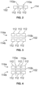
- Figure 2 illustrates a top plan view of air curtains 110a between adjacent seats 112 within the internal cabin 102, not according to the claims.
- the seats 112 are in a group within the row 114.
- one or more of the outflow vents 108 are configured to output an air curtain 110a between adjacent seats 112.
- Figure 3 illustrates a top plan view of an air curtain 110b between adjacent rows 114a and 114b within the internal cabin 102, according to an embodiment of the present disclosure.
- the seats 112 within the first row 114a are in a first group, and the seats 112 within the second rows 114b are in a second group.
- the first row 114a is adjacent the second row 114b.
- one or more of the outflow vents 108 are configured to output the air curtain 110b between the adjacent rows 114a and 114b.
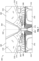
- Figure 4 illustrates a top plan view of first air curtains 110a between adjacent seats 112 within rows 114a and 114b and a second air curtain 110b between adjacent rows 114a and 114b within the internal cabin 102, according to an embodiment of the present disclosure.
- the first air curtains 110a may be perpendicular to the second air curtain 110b.
- one or more of the outflow vents 108 are configured to output the air curtains 110a between adjacent seats 112, and the air curtain 110b between the adjacent rows 114a and 114b.
- FIG. 5 illustrates a perspective front view of an aircraft 210, according to an embodiment of the present disclosure.
- the aircraft 210 is an example of the vehicle 104 shown in Figure 1 .
- the aircraft 210 includes a propulsion system 212 that includes engines 214, for example.
- the propulsion system 212 may include more engines 14 than shown.
- the engines 214 are carried by wings 216 of the aircraft 210.
- the engines 214 may be carried by a fuselage 218 and/or an empennage 220.
- the empennage 220 may also support horizontal stabilizers 222 and a vertical stabilizer 224.
- the fuselage 218 of the aircraft 210 defines an internal cabin 230 (such as the internal cabin 102 shown in Figure 1 ), which includes a flight deck or cockpit, one or more work sections (for example, galleys, personnel carry-on baggage areas, and the like), one or more passenger sections (for example, first class, business class, and coach sections), one or more lavatories, and/or the like.
- an internal cabin 230 such as the internal cabin 102 shown in Figure 1
- work sections for example, galleys, personnel carry-on baggage areas, and the like
- passenger sections for example, first class, business class, and coach sections
- lavatories lavatories
- embodiments of the present disclosure may be used with various other vehicles, such as automobiles, buses, locomotives and train cars, watercraft, spacecraft, and the like. Further, embodiments of the present disclosure may be used with respect to fixed structures, such as commercial and residential buildings.
- FIG. 6A illustrates a top plan view of an internal cabin 230 of an aircraft, according to an embodiment of the present disclosure.
- the internal cabin 230 may be within the fuselage 232 of the aircraft, such as the fuselage 218 of Figure 5 .
- one or more fuselage walls may define the internal cabin 230.
- the internal cabin 230 includes multiple sections, including a front section 233, a first class section 234, a business class section 236, a front galley station 238, an expanded economy or coach section 240, a standard economy of coach section 242, and an aft section 244, which may include multiple lavatories and galley stations.
- the internal cabin 230 may include more or less sections than shown.
- the internal cabin 230 may not include a first class section, and may include more or less galley stations than shown.
- Each of the sections may be separated by a cabin transition area 246, which may include class divider assemblies between aisles 248.
- the internal cabin 230 includes two aisles 250 and 252 that lead to the aft section 244.
- the internal cabin 230 may have less or more aisles than shown.
- the internal cabin 230 may include a single aisle that extends through the center of the internal cabin 230 that leads to the aft section 244.
- the aisles 248, 250, and 252 extend to egress paths or door passageways 260. Exit doors 262 are located at ends of the egress paths 260.
- the egress paths 260 may be perpendicular to the aisles 248, 250, and 252.
- the internal cabin 230 may include more egress paths 260 at different locations than shown.
- the air curtain system 100 shown and described with respect to Figures 1-4 may be used within the internal cabin 230.
- Figure 6B illustrates a top plan view of an internal cabin 280 of an aircraft, according to an embodiment of the present disclosure.
- the internal cabin 280 is an example of the internal cabin 230 shown in Figure 5 .
- the internal cabin 280 may be within a fuselage 281 of the aircraft.
- one or more fuselage walls may define the internal cabin 280.
- the internal cabin 280 includes multiple sections, including a main cabin 282 having passenger seats 283, and an aft section 285 behind the main cabin 282. It is to be understood that the internal cabin 280 may include more or less sections than shown.
- the internal cabin 280 may include a single aisle 284 that leads to the aft section 285.
- the single aisle 284 may extend through the center of the internal cabin 280 that leads to the aft section 285.
- the single aisle 284 may be coaxially aligned with a central longitudinal plane of the internal cabin 280.
- the aisle 284 extends to an egress path or door passageway 290. Exit doors 292 are located at ends of the egress path 290.
- the egress path 290 may be perpendicular to the aisle 284.
- the internal cabin 280 may include more egress paths than shown.
- the air curtain system 100 shown and described with respect to Figures 1-4 may be used within the internal cabin 280.
- Figure 7 illustrates a perspective interior view of an internal cabin 300 of an aircraft, according to an embodiment of the present disclosure.
- the internal cabin 300 is an example of the internal cabin 102 shown in Figure 1 .
- the internal cabin 300 includes outboard walls 302 connected to a ceiling 304.
- Windows 306 may be formed within the outboard walls 302.
- a floor 308 supports rows of seats 310.
- a row 312 may include two seats 310 on either side of an aisle 313. However, the row 312 may include more or less seats 310 than shown. Additionally, the internal cabin 300 may include more aisles than shown.
- PSUs 314 are secured between an outboard wall 302 and the ceiling 304 on either side of the aisle 313.
- the PSUs 314 extend between a front end and rear end of the internal cabin 300.
- a PSU 314 may be positioned over each seat 310 within a row 312.
- Each PSU 314 may include a housing 316 that generally contains vents, reading lights, an oxygen bag drop panel, an attendant request button, and other such controls over each seat 310 (or groups of seats) within a row 312.
- Overhead stowage bin assemblies 318 are secured to the ceiling 304 and/or the outboard wall 302 above and inboard from the PSU 314 on either side of the aisle 313.
- the overhead stowage bin assemblies 318 are secured over the seats 310.
- the overhead stowage bin assemblies 318 extend between the front and rear end of the internal cabin 300.
- Each stowage bin assembly 318 may include a pivot bin or bucket 320 pivotally secured to a strongback.
- the overhead stowage bin assemblies 318 may be positioned above and inboard from lower surfaces of the PSUs 314.
- the overhead stowage bin assemblies 318 are configured to be pivoted open in order to receive passenger carry-on baggage and personal items, for example.
- outboard means a position that is further away from a central longitudinal plane 322 of the internal cabin 300 as compared to another component.
- inboard means a position that is closer to the central longitudinal plane 322 of the internal cabin 300 as compared to another component.
- a lower surface of a PSU 314 may be outboard in relation to a stowage bin assembly 318.
- a vehicle 104 comprising: an internal cabin 102; a first group of seats 112 within a first row within the internal cabin 102; a second group of seats 112 within a second row within the internal cabin 102, wherein the first row is adjacent the second row; and an air curtain system 100 within the internal cabin 102, wherein the air curtain system 100 is configured to provide one or more air curtains 110 between (a) the first row and the second row and optionally also between (b) adjacent seats 112 of one or both of the first group or the second group, wherein the air curtain system 100 comprises: one or more outflow vents 108 that output the one or more air curtains 110; an airflow generator 106 that generates airflow that is received by the one or more outflow vents 108; one or more return vents 116 that receive the one or more air curtains 110; a control unit 124 that is configured to control positions of one or both of the one or more outflow vents 108 or the one or more return vents 116 in response to positions of the seats 112;
- the air curtain systems and methods are configured to provide air curtains between adjacent rows or seats and/or adjacent seats within the rows, thereby reducing the spread of pathogens between passengers onboard a vehicle during a trip.
- a structure, limitation, or element that is "configured to” perform a task or operation is particularly structurally formed, constructed, or adapted in a manner corresponding to the task or operation.
- an object that is merely capable of being modified to perform the task or operation is not “configured to” perform the task or operation as used herein.
- value modifiers such as “about,” “substantially,” and “approximately” inserted before a numerical value indicate that the value can represent other values within a designated threshold range above and/or below the specified value, such as values within 5%, 10%, or 15% of the specified value.
Landscapes
- Engineering & Computer Science (AREA)
- Aviation & Aerospace Engineering (AREA)
- Mechanical Engineering (AREA)
- Health & Medical Sciences (AREA)
- General Health & Medical Sciences (AREA)
- Pulmonology (AREA)
- Chemical & Material Sciences (AREA)
- Combustion & Propulsion (AREA)
- General Engineering & Computer Science (AREA)
- Air-Conditioning For Vehicles (AREA)
Claims (15)
- Fahrzeug (104), umfassend:eine Innenkabine (102);eine erste Gruppe von Sitzen (112) innerhalb einer ersten Reihe innerhalb der Innenkabine (102);eine zweite Gruppe von Sitzen (112) innerhalb einer zweiten Reihe innerhalb der Innenkabine (102), wobei die erste Reihe an die zweite Reihe angrenzt; undein Luftschleiersystem (100) innerhalb der Innenkabine (102), wobei das Luftschleiersystem (100) eine oder mehrere lichtemittierende Vorrichtungen (111) umfasst, die konfiguriert sind, um Licht entlang mindestens eines Abschnitts eines oder mehrerer Luftschleier (110) zu emittieren, um die Anwesenheit des einen oder der mehreren Luftschleier (110) anzugeben, indem sie nur aktiviert werden, wenn der eine oder die mehreren Luftschleier bereitgestellt werden,wobei das Luftschleiersystem (100) konfiguriert ist, um den einen oder die mehreren Luftschleier (110) zwischen der ersten Reihe und der zweiten Reihe bereitzustellen.
- Fahrzeug (104) nach Anspruch 1, wobei das Luftschleiersystem (100) weiter konfiguriert ist, um einen oder mehrere Luftschleier (110) zwischen angrenzenden Sitzen (112) einer oder beider der ersten Gruppe oder der zweiten Gruppe bereitzustellen.
- Fahrzeug (104) nach Anspruch 1 oder 2, wobei das Luftschleiersystem (100) eine oder mehrere Ausströmöffnungen (108) umfasst, die den einen oder die mehreren Luftschleier (110) ausgeben.
- Fahrzeug (104) nach Anspruch 3, wobei die eine oder die mehreren Ausströmöffnungen (108) oberhalb der Sitze (112) angeordnet sind.
- Fahrzeug (104) nach Anspruch 3, wobei die eine oder die mehreren Ausströmöffnungen (108) innerhalb der Sitze (112) angeordnet sind.
- Fahrzeug (104) nach Anspruch 3, 4 oder 5, wobei das Luftschleiersystem (100) weiter einen Luftstromgenerator (106) umfasst, der einen Luftstrom erzeugt, der von der einen oder den mehreren Ausströmöffnungen (108) empfangen wird.
- Fahrzeug (104) nach Anspruch 6, wobei der Luftstromgenerator (106) innerhalb eines oder mehrerer der Sitze (112) enthalten ist.
- Fahrzeug (104) nach einem der Ansprüche 3-7, wobei das Luftschleiersystem (100) weiter eine oder mehrere Rücklauföffnungen (116) umfasst, die den einen oder die mehreren Luftschleier (110) empfangen.
- Fahrzeug (104) nach Anspruch 8, wobei die eine oder die mehreren Rücklauföffnungen (116) unter den Sitzen (112) angeordnet sind.
- Fahrzeug (104) nach Anspruch 8, wobei die eine oder die mehreren Rücklauföffnungen (116) innerhalb der Sitze (112) angeordnet sind.
- Fahrzeug (104) nach einem der Ansprüche 3-10, wobei das Luftschleiersystem (100) weiter eine Steuerungseinheit (124) umfasst, die konfiguriert ist, um Positionen der einen oder der mehreren Ausströmöffnungen (108) in Reaktion auf Positionen der Sitze (112) zu steuern.
- Luftschleierverfahren für ein Fahrzeug (104) nach einem der Ansprüche 1-11, wobei das Luftschleierverfahren folgendes umfasst:
Bereitstellen, durch das Luftschleiersystem (100) innerhalb der Innenkabine (102), eines oder mehrerer Luftschleier (110) zwischen (a) der ersten Reihe und der zweiten Reihe und optional für ein Fahrzeug nach Anspruch 2 oder einem der Ansprüche 3-11, wenn abhängig von Anspruch 2, zwischen (b) benachbarten Sitzen (112) einer oder beider der ersten Gruppe oder der zweiten Gruppe. - Luftschleierverfahren nach Anspruch 12, wobei das Bereitstellen das Ausgeben, durch eine oder mehrere Ausströmöffnungen (108), des einen oder der mehreren Luftschleier (110) umfasst.
- Luftschleierverfahren nach Anspruch 13, weiter umfassend Anordnen einer oder mehrerer Ausströmöffnungen (108) oberhalb der Sitze (112).
- Luftschleierverfahren nach Anspruch 13 oder 14, weiter umfassend Anordnen einer oder mehrerer Ausströmöffnungen (108) innerhalb der Sitze (112).
Applications Claiming Priority (2)
| Application Number | Priority Date | Filing Date | Title |
|---|---|---|---|
| US202063047284P | 2020-07-02 | 2020-07-02 | |
| US17/352,537 US12187440B2 (en) | 2020-07-02 | 2021-06-21 | Air curtain systems and methods for internal cabins of vehicles |
Publications (2)
| Publication Number | Publication Date |
|---|---|
| EP3932809A1 EP3932809A1 (de) | 2022-01-05 |
| EP3932809B1 true EP3932809B1 (de) | 2024-11-20 |
Family
ID=76764910
Family Applications (1)
| Application Number | Title | Priority Date | Filing Date |
|---|---|---|---|
| EP21183440.3A Active EP3932809B1 (de) | 2020-07-02 | 2021-07-02 | Luftschleiersysteme und -verfahren für innenkabinen von fahrzeugen |
Country Status (4)
| Country | Link |
|---|---|
| US (1) | US12187440B2 (de) |
| EP (1) | EP3932809B1 (de) |
| JP (1) | JP7726683B2 (de) |
| CN (1) | CN113879541A (de) |
Families Citing this family (2)
| Publication number | Priority date | Publication date | Assignee | Title |
|---|---|---|---|---|
| US20210387737A1 (en) * | 2020-06-10 | 2021-12-16 | Walter Dorwin Teague Associates, Inc. | Passenger air shield |
| US20220041288A1 (en) * | 2020-08-04 | 2022-02-10 | B/E Aerospace, Inc. | Aircraft seats with air vents |
Family Cites Families (16)
| Publication number | Priority date | Publication date | Assignee | Title |
|---|---|---|---|---|
| US4742760A (en) | 1987-07-06 | 1988-05-10 | The Boeing Company | Aircraft cabin ventilation system |
| JPH01178536U (de) * | 1988-06-03 | 1989-12-21 | ||
| KR960000557A (ko) | 1994-06-23 | 1996-01-25 | 배순훈 | 에어커튼(Air-Curtain)을 이용한 차량 자동온도 조절 시스템 |
| JP3197497B2 (ja) * | 1996-12-17 | 2001-08-13 | 日本たばこ産業株式会社 | 負圧型室内分煙機構及び航空機内喫煙ブース |
| KR100527136B1 (ko) * | 2003-11-18 | 2005-11-09 | 현대자동차주식회사 | 버스 출입문을 통한 배기 오염물질 유입 차단 시스템 |
| US10029797B2 (en) | 2008-09-30 | 2018-07-24 | The Boeing Company | Personal ventilation in an aircraft environment |
| US9050382B2 (en) | 2013-03-12 | 2015-06-09 | Peter Carr | Close proximity airborne influenza/pathogen mitigator |
| KR101480442B1 (ko) | 2013-04-16 | 2015-01-14 | 한국항공우주연구원 | 항공기 좌석용 공기막 형성장치 |
| EP3090948A1 (de) | 2015-05-08 | 2016-11-09 | Raymond R M Wang | Luftstrommodifizierungsvorrichtung und verfahren |
| KR20170114553A (ko) * | 2016-04-05 | 2017-10-16 | (주)유아이 | 에어커튼 시스템을 갖는 버스 |
| US20190077215A1 (en) | 2017-09-12 | 2019-03-14 | Ford Global Technologies, Llc | System and method for personalized thermal comfort in a vehicle passenger cabin |
| EP3457047B1 (de) * | 2017-09-15 | 2023-01-04 | IQAir AG | Personalisierte luftreinigungsvorrichtung |
| GB2575784B (en) * | 2018-07-19 | 2022-04-27 | Bentley Motors Ltd | Zone separation in a vehicle |
| GB2579547A (en) * | 2018-11-30 | 2020-07-01 | Jaguar Land Rover Ltd | A vehicle system |
| JP6669845B1 (ja) * | 2018-12-25 | 2020-03-18 | 日機装株式会社 | 感染抑制装置 |
| US11859864B1 (en) * | 2020-05-18 | 2024-01-02 | Wunderlich-Malec Engineering, Inc. | Particulate and virus barrier |
-
2021
- 2021-06-21 US US17/352,537 patent/US12187440B2/en active Active
- 2021-07-02 CN CN202110752495.3A patent/CN113879541A/zh active Pending
- 2021-07-02 JP JP2021110548A patent/JP7726683B2/ja active Active
- 2021-07-02 EP EP21183440.3A patent/EP3932809B1/de active Active
Also Published As
| Publication number | Publication date |
|---|---|
| US20220001993A1 (en) | 2022-01-06 |
| JP2022013916A (ja) | 2022-01-18 |
| JP7726683B2 (ja) | 2025-08-20 |
| EP3932809A1 (de) | 2022-01-05 |
| CN113879541A (zh) | 2022-01-04 |
| US12187440B2 (en) | 2025-01-07 |
Similar Documents
| Publication | Publication Date | Title |
|---|---|---|
| US12048787B2 (en) | Infection preventing device | |
| US11999490B2 (en) | Air curtain systems and methods for vehicle cabins | |
| US12214886B2 (en) | Ventilation systems and methods for internal cabins of vehicles | |
| US20100081369A1 (en) | Personal ventilation in an aircraft environment | |
| EP3932809B1 (de) | Luftschleiersysteme und -verfahren für innenkabinen von fahrzeugen | |
| US12371170B2 (en) | Ventilation systems and methods for internal cabins of vehicles | |
| EP2931605B1 (de) | Flugzeug-zirkulationssystem für passagierkabinen | |
| EP4177164B1 (de) | Sitzanordnung mit integriertem beleuchtungssystem | |
| RU2616490C2 (ru) | Система кондиционирования воздуха транспортного средства и оснащенное этой системой железнодорожное транспортное средство | |
| JP7830037B2 (ja) | 航空機で使用するための給気システム | |
| CN114104295A (zh) | 用于交通工具的内部舱室的通风系统和方法 | |
| US11383842B2 (en) | Ventilated vehicle seat systems and methods | |
| EP3954610A1 (de) | Flugzeugsitze mit belüftungsöffnungen | |
| EP3988452B1 (de) | Belüftungssysteme für kopfstützen und verfahren für sitzanordnungen | |
| US20220041288A1 (en) | Aircraft seats with air vents | |
| US10377492B1 (en) | Illuminating ceiling systems and methods for an internal cabin of a vehicle | |
| US20190248282A1 (en) | Aircraft window sidewall panel illumination systems and methods | |
| EP4101474B1 (de) | Systeme zum beweglichen halten einer uv-lampe in einem geschlossenen raum | |
| EP4400410A1 (de) | Austauschbare luftverteilungskupplungsschnittstelle für eine innenkabine eines fahrzeugs | |
| JPH11105795A (ja) | 交通機関の分煙装置 | |
| BR102019009387A2 (pt) | sistema de insuflação de ar integrado ao piso e poltronas de cabine de aeronave | |
| TH154305A (th) | เครื่องส่งเสริมการไหลเวียนของอากาศสำหรับยานพาหนะ | |
| TH66796B (th) | เครื่องส่งเสริมการไหลเวียนของอากาศสำหรับยานพาหนะ |
Legal Events
| Date | Code | Title | Description |
|---|---|---|---|
| PUAI | Public reference made under article 153(3) epc to a published international application that has entered the european phase |
Free format text: ORIGINAL CODE: 0009012 |
|
| STAA | Information on the status of an ep patent application or granted ep patent |
Free format text: STATUS: THE APPLICATION HAS BEEN PUBLISHED |
|
| AK | Designated contracting states |
Kind code of ref document: A1 Designated state(s): AL AT BE BG CH CY CZ DE DK EE ES FI FR GB GR HR HU IE IS IT LI LT LU LV MC MK MT NL NO PL PT RO RS SE SI SK SM TR |
|
| B565 | Issuance of search results under rule 164(2) epc |
Effective date: 20211126 |
|
| STAA | Information on the status of an ep patent application or granted ep patent |
Free format text: STATUS: REQUEST FOR EXAMINATION WAS MADE |
|
| 17P | Request for examination filed |
Effective date: 20220307 |
|
| RBV | Designated contracting states (corrected) |
Designated state(s): AL AT BE BG CH CY CZ DE DK EE ES FI FR GB GR HR HU IE IS IT LI LT LU LV MC MK MT NL NO PL PT RO RS SE SI SK SM TR |
|
| RAP3 | Party data changed (applicant data changed or rights of an application transferred) |
Owner name: THE BOEING COMPANY |
|
| STAA | Information on the status of an ep patent application or granted ep patent |
Free format text: STATUS: EXAMINATION IS IN PROGRESS |
|
| 17Q | First examination report despatched |
Effective date: 20230419 |
|
| GRAP | Despatch of communication of intention to grant a patent |
Free format text: ORIGINAL CODE: EPIDOSNIGR1 |
|
| STAA | Information on the status of an ep patent application or granted ep patent |
Free format text: STATUS: GRANT OF PATENT IS INTENDED |
|
| INTG | Intention to grant announced |
Effective date: 20240703 |
|
| P01 | Opt-out of the competence of the unified patent court (upc) registered |
Free format text: CASE NUMBER: APP_47070/2024 Effective date: 20240814 |
|
| GRAS | Grant fee paid |
Free format text: ORIGINAL CODE: EPIDOSNIGR3 |
|
| GRAA | (expected) grant |
Free format text: ORIGINAL CODE: 0009210 |
|
| STAA | Information on the status of an ep patent application or granted ep patent |
Free format text: STATUS: THE PATENT HAS BEEN GRANTED |
|
| AK | Designated contracting states |
Kind code of ref document: B1 Designated state(s): AL AT BE BG CH CY CZ DE DK EE ES FI FR GB GR HR HU IE IS IT LI LT LU LV MC MK MT NL NO PL PT RO RS SE SI SK SM TR |
|
| REG | Reference to a national code |
Ref country code: GB Ref legal event code: FG4D |
|
| REG | Reference to a national code |
Ref country code: CH Ref legal event code: EP |
|
| REG | Reference to a national code |
Ref country code: DE Ref legal event code: R096 Ref document number: 602021021986 Country of ref document: DE |
|
| REG | Reference to a national code |
Ref country code: IE Ref legal event code: FG4D |
|
| REG | Reference to a national code |
Ref country code: LT Ref legal event code: MG9D |
|
| REG | Reference to a national code |
Ref country code: NL Ref legal event code: MP Effective date: 20241120 |
|
| PG25 | Lapsed in a contracting state [announced via postgrant information from national office to epo] |
Ref country code: PT Free format text: LAPSE BECAUSE OF FAILURE TO SUBMIT A TRANSLATION OF THE DESCRIPTION OR TO PAY THE FEE WITHIN THE PRESCRIBED TIME-LIMIT Effective date: 20250320 Ref country code: IS Free format text: LAPSE BECAUSE OF FAILURE TO SUBMIT A TRANSLATION OF THE DESCRIPTION OR TO PAY THE FEE WITHIN THE PRESCRIBED TIME-LIMIT Effective date: 20250320 Ref country code: HR Free format text: LAPSE BECAUSE OF FAILURE TO SUBMIT A TRANSLATION OF THE DESCRIPTION OR TO PAY THE FEE WITHIN THE PRESCRIBED TIME-LIMIT Effective date: 20241120 |
|
| PG25 | Lapsed in a contracting state [announced via postgrant information from national office to epo] |
Ref country code: FI Free format text: LAPSE BECAUSE OF FAILURE TO SUBMIT A TRANSLATION OF THE DESCRIPTION OR TO PAY THE FEE WITHIN THE PRESCRIBED TIME-LIMIT Effective date: 20241120 Ref country code: NL Free format text: LAPSE BECAUSE OF FAILURE TO SUBMIT A TRANSLATION OF THE DESCRIPTION OR TO PAY THE FEE WITHIN THE PRESCRIBED TIME-LIMIT Effective date: 20241120 |
|
| REG | Reference to a national code |
Ref country code: AT Ref legal event code: MK05 Ref document number: 1743375 Country of ref document: AT Kind code of ref document: T Effective date: 20241120 |
|
| PG25 | Lapsed in a contracting state [announced via postgrant information from national office to epo] |
Ref country code: BG Free format text: LAPSE BECAUSE OF FAILURE TO SUBMIT A TRANSLATION OF THE DESCRIPTION OR TO PAY THE FEE WITHIN THE PRESCRIBED TIME-LIMIT Effective date: 20241120 |
|
| PG25 | Lapsed in a contracting state [announced via postgrant information from national office to epo] |
Ref country code: ES Free format text: LAPSE BECAUSE OF FAILURE TO SUBMIT A TRANSLATION OF THE DESCRIPTION OR TO PAY THE FEE WITHIN THE PRESCRIBED TIME-LIMIT Effective date: 20241120 |
|
| PG25 | Lapsed in a contracting state [announced via postgrant information from national office to epo] |
Ref country code: NO Free format text: LAPSE BECAUSE OF FAILURE TO SUBMIT A TRANSLATION OF THE DESCRIPTION OR TO PAY THE FEE WITHIN THE PRESCRIBED TIME-LIMIT Effective date: 20250220 |
|
| PG25 | Lapsed in a contracting state [announced via postgrant information from national office to epo] |
Ref country code: GR Free format text: LAPSE BECAUSE OF FAILURE TO SUBMIT A TRANSLATION OF THE DESCRIPTION OR TO PAY THE FEE WITHIN THE PRESCRIBED TIME-LIMIT Effective date: 20250221 Ref country code: LV Free format text: LAPSE BECAUSE OF FAILURE TO SUBMIT A TRANSLATION OF THE DESCRIPTION OR TO PAY THE FEE WITHIN THE PRESCRIBED TIME-LIMIT Effective date: 20241120 Ref country code: AT Free format text: LAPSE BECAUSE OF FAILURE TO SUBMIT A TRANSLATION OF THE DESCRIPTION OR TO PAY THE FEE WITHIN THE PRESCRIBED TIME-LIMIT Effective date: 20241120 |
|
| PG25 | Lapsed in a contracting state [announced via postgrant information from national office to epo] |
Ref country code: PL Free format text: LAPSE BECAUSE OF FAILURE TO SUBMIT A TRANSLATION OF THE DESCRIPTION OR TO PAY THE FEE WITHIN THE PRESCRIBED TIME-LIMIT Effective date: 20241120 |
|
| PG25 | Lapsed in a contracting state [announced via postgrant information from national office to epo] |
Ref country code: RS Free format text: LAPSE BECAUSE OF FAILURE TO SUBMIT A TRANSLATION OF THE DESCRIPTION OR TO PAY THE FEE WITHIN THE PRESCRIBED TIME-LIMIT Effective date: 20250220 |
|
| PG25 | Lapsed in a contracting state [announced via postgrant information from national office to epo] |
Ref country code: SM Free format text: LAPSE BECAUSE OF FAILURE TO SUBMIT A TRANSLATION OF THE DESCRIPTION OR TO PAY THE FEE WITHIN THE PRESCRIBED TIME-LIMIT Effective date: 20241120 |
|
| PG25 | Lapsed in a contracting state [announced via postgrant information from national office to epo] |
Ref country code: DK Free format text: LAPSE BECAUSE OF FAILURE TO SUBMIT A TRANSLATION OF THE DESCRIPTION OR TO PAY THE FEE WITHIN THE PRESCRIBED TIME-LIMIT Effective date: 20241120 |
|
| PG25 | Lapsed in a contracting state [announced via postgrant information from national office to epo] |
Ref country code: EE Free format text: LAPSE BECAUSE OF FAILURE TO SUBMIT A TRANSLATION OF THE DESCRIPTION OR TO PAY THE FEE WITHIN THE PRESCRIBED TIME-LIMIT Effective date: 20241120 |
|
| PG25 | Lapsed in a contracting state [announced via postgrant information from national office to epo] |
Ref country code: RO Free format text: LAPSE BECAUSE OF FAILURE TO SUBMIT A TRANSLATION OF THE DESCRIPTION OR TO PAY THE FEE WITHIN THE PRESCRIBED TIME-LIMIT Effective date: 20241120 |
|
| PG25 | Lapsed in a contracting state [announced via postgrant information from national office to epo] |
Ref country code: SK Free format text: LAPSE BECAUSE OF FAILURE TO SUBMIT A TRANSLATION OF THE DESCRIPTION OR TO PAY THE FEE WITHIN THE PRESCRIBED TIME-LIMIT Effective date: 20241120 |
|
| PG25 | Lapsed in a contracting state [announced via postgrant information from national office to epo] |
Ref country code: CZ Free format text: LAPSE BECAUSE OF FAILURE TO SUBMIT A TRANSLATION OF THE DESCRIPTION OR TO PAY THE FEE WITHIN THE PRESCRIBED TIME-LIMIT Effective date: 20241120 |
|
| PG25 | Lapsed in a contracting state [announced via postgrant information from national office to epo] |
Ref country code: IT Free format text: LAPSE BECAUSE OF FAILURE TO SUBMIT A TRANSLATION OF THE DESCRIPTION OR TO PAY THE FEE WITHIN THE PRESCRIBED TIME-LIMIT Effective date: 20241120 |
|
| REG | Reference to a national code |
Ref country code: DE Ref legal event code: R097 Ref document number: 602021021986 Country of ref document: DE |
|
| PG25 | Lapsed in a contracting state [announced via postgrant information from national office to epo] |
Ref country code: SE Free format text: LAPSE BECAUSE OF FAILURE TO SUBMIT A TRANSLATION OF THE DESCRIPTION OR TO PAY THE FEE WITHIN THE PRESCRIBED TIME-LIMIT Effective date: 20241120 |
|
| PLBE | No opposition filed within time limit |
Free format text: ORIGINAL CODE: 0009261 |
|
| STAA | Information on the status of an ep patent application or granted ep patent |
Free format text: STATUS: NO OPPOSITION FILED WITHIN TIME LIMIT |
|
| PGFP | Annual fee paid to national office [announced via postgrant information from national office to epo] |
Ref country code: DE Payment date: 20250729 Year of fee payment: 5 |
|
| PGFP | Annual fee paid to national office [announced via postgrant information from national office to epo] |
Ref country code: GB Payment date: 20250728 Year of fee payment: 5 |
|
| PGFP | Annual fee paid to national office [announced via postgrant information from national office to epo] |
Ref country code: FR Payment date: 20250725 Year of fee payment: 5 |
|
| 26N | No opposition filed |
Effective date: 20250821 |
|
| REG | Reference to a national code |
Ref country code: CH Ref legal event code: H13 Free format text: ST27 STATUS EVENT CODE: U-0-0-H10-H13 (AS PROVIDED BY THE NATIONAL OFFICE) Effective date: 20260224 |
|
| PG25 | Lapsed in a contracting state [announced via postgrant information from national office to epo] |
Ref country code: LU Free format text: LAPSE BECAUSE OF NON-PAYMENT OF DUE FEES Effective date: 20250702 |
|
| REG | Reference to a national code |
Ref country code: BE Ref legal event code: MM Effective date: 20250731 |
|
| PG25 | Lapsed in a contracting state [announced via postgrant information from national office to epo] |
Ref country code: BE Free format text: LAPSE BECAUSE OF NON-PAYMENT OF DUE FEES Effective date: 20250731 |
|
| PG25 | Lapsed in a contracting state [announced via postgrant information from national office to epo] |
Ref country code: CH Free format text: LAPSE BECAUSE OF NON-PAYMENT OF DUE FEES Effective date: 20250731 |