EP3932829A2 - Récipient pour marchandise dangereuse - Google Patents
Récipient pour marchandise dangereuse Download PDFInfo
- Publication number
- EP3932829A2 EP3932829A2 EP21177777.6A EP21177777A EP3932829A2 EP 3932829 A2 EP3932829 A2 EP 3932829A2 EP 21177777 A EP21177777 A EP 21177777A EP 3932829 A2 EP3932829 A2 EP 3932829A2
- Authority
- EP
- European Patent Office
- Prior art keywords
- goods container
- hazardous goods
- container according
- sliding gate
- hazardous
- Prior art date
- Legal status (The legal status is an assumption and is not a legal conclusion. Google has not performed a legal analysis and makes no representation as to the accuracy of the status listed.)
- Granted
Links
Images


Classifications
-
- B—PERFORMING OPERATIONS; TRANSPORTING
- B65—CONVEYING; PACKING; STORING; HANDLING THIN OR FILAMENTARY MATERIAL
- B65D—CONTAINERS FOR STORAGE OR TRANSPORT OF ARTICLES OR MATERIALS, e.g. BAGS, BARRELS, BOTTLES, BOXES, CANS, CARTONS, CRATES, DRUMS, JARS, TANKS, HOPPERS, FORWARDING CONTAINERS; ACCESSORIES, CLOSURES, OR FITTINGS THEREFOR; PACKAGING ELEMENTS; PACKAGES
- B65D90/00—Component parts, details or accessories for large containers
- B65D90/008—Doors for containers, e.g. ISO-containers
-
- B—PERFORMING OPERATIONS; TRANSPORTING
- B65—CONVEYING; PACKING; STORING; HANDLING THIN OR FILAMENTARY MATERIAL
- B65D—CONTAINERS FOR STORAGE OR TRANSPORT OF ARTICLES OR MATERIALS, e.g. BAGS, BARRELS, BOTTLES, BOXES, CANS, CARTONS, CRATES, DRUMS, JARS, TANKS, HOPPERS, FORWARDING CONTAINERS; ACCESSORIES, CLOSURES, OR FITTINGS THEREFOR; PACKAGING ELEMENTS; PACKAGES
- B65D90/00—Component parts, details or accessories for large containers
- B65D90/22—Safety features
- B65D90/24—Spillage-retaining means, e.g. recovery ponds
-
- E—FIXED CONSTRUCTIONS
- E06—DOORS, WINDOWS, SHUTTERS, OR ROLLER BLINDS IN GENERAL; LADDERS
- E06B—FIXED OR MOVABLE CLOSURES FOR OPENINGS IN BUILDINGS, VEHICLES, FENCES OR LIKE ENCLOSURES IN GENERAL, e.g. DOORS, WINDOWS, BLINDS, GATES
- E06B3/00—Window sashes, door leaves, or like elements for closing wall or like openings; Layout of fixed or moving closures, e.g. windows in wall or like openings; Features of rigidly-mounted outer frames relating to the mounting of wing frames
- E06B3/32—Arrangements of wings characterised by the manner of movement; Arrangements of movable wings in openings; Features of wings or frames relating solely to the manner of movement of the wing
- E06B3/34—Arrangements of wings characterised by the manner of movement; Arrangements of movable wings in openings; Features of wings or frames relating solely to the manner of movement of the wing with only one kind of movement
- E06B3/42—Sliding wings; Details of frames with respect to guiding
- E06B3/46—Horizontally-sliding wings
- E06B3/469—Arrangements at the overlapping vertical edges of the wings that engage when closing
-
- E—FIXED CONSTRUCTIONS
- E06—DOORS, WINDOWS, SHUTTERS, OR ROLLER BLINDS IN GENERAL; LADDERS
- E06B—FIXED OR MOVABLE CLOSURES FOR OPENINGS IN BUILDINGS, VEHICLES, FENCES OR LIKE ENCLOSURES IN GENERAL, e.g. DOORS, WINDOWS, BLINDS, GATES
- E06B5/00—Doors, windows, or like closures for special purposes; Border constructions therefor
- E06B5/10—Doors, windows, or like closures for special purposes; Border constructions therefor for protection against air-raid or other war-like action; for other protective purposes
- E06B5/16—Fireproof doors or similar closures; Adaptations of fixed constructions therefor
- E06B5/164—Sealing arrangements between the door or window and its frame, e.g. intumescent seals specially adapted therefor
Definitions
- the present invention relates to a hazardous goods container, in particular as a fire protection container, with a bottom collecting trough, a roof and side walls connecting the collecting trough and the roof, which are fixed to a frame.
- the hazardous goods container can have a stable structure that has a fire resistance of at least 90 minutes in the event of a fire.
- a pivotable door is provided on a side wall, which provides access to the interior of the hazardous goods container, which can be designed as a storage rack or can be walked on by people.
- the access opening for filling the dangerous goods container is relatively small, so that the storage of containers is laborious.
- the space in front of the hazardous goods container must be kept free so as not to block the door.
- At least one sliding gate for opening and closing an opening on the dangerous goods container is movably mounted on at least one side.
- the at least one sliding door preferably extends over at least 80% of the height of the hazardous goods container, so that filling and unloading of containers can take place essentially over almost the entire height in the horizontal direction along the access opening.
- two sliding gates can be arranged on one side in different planes, so that each sliding gate covers an access opening on the container.
- the two sliding gates can preferably cover at least 80% of the area of the side wall, so that each sliding gate can release almost half of the area of the side wall for filling and unloading.
- the side wall with the two sliding gates is preferably arranged on a longitudinal side of the hazardous goods container.
- sliding gates can also be provided on both long sides so that the hazardous goods container can be filled and unloaded from opposite sides.
- the dangerous goods container preferably has a frame with an inner frame inside the side walls and the roof and an outer frame outside the side walls and the roof.
- the inner framework can be constructed essentially in the shape of a parallelepiped and comprise several posts which support an upper frame below the roof.
- the posts can be fixed or supported on the drip pan, which is preferably made from a bent sheet steel.
- the side walls and the roof can then be fixed to the inner framework, panels preferably being used for this purpose which have a core made of fire-retardant material which is covered on both sides with a sheet metal.
- the scaffolding also includes an outer scaffolding that is arranged outside the side walls and the roof and also has posts and a frame in the area of the roof in order to securely fix the roof and the side walls.
- the at least one sliding gate is supported on rollers and guided on a top side via a guide rail.
- the weight forces of the sliding gate are then carried off by the rollers, so that on the top, which is more heavily loaded in the event of fire, only the sliding gate is supported on the side.
- the rollers are preferably held on the sliding gate and can be moved along a running rail which is supported on a floor section of the hazardous goods container.
- a guide rail is provided, which is preferably fixed to an upper side of the sliding gate and can be moved along rotatable but stationary guide rollers or sliding elements.
- the guide rail could also be fixed to the roof of the container, with rollers or sliding elements being arranged on the upper side of the sliding gate.
- the guide rail is preferably U-shaped in cross-section and, when fixed on an upper side of the sliding gate, has upwardly projecting legs, between which sliding elements and / or guide rollers are then arranged.
- each sliding gate is preferably biased into a closed position via a spring element.
- a spring element can, for example, have a weight which can be moved via a cable pull and which can be moved up and down in a pocket on a side wall, for example. This allows the sliding gate to close automatically from an open position in the event of a fire.
- the sliding gate can also be moved in the opening or closing direction via a drive, in particular an electric drive.
- At least one damper can preferably be provided.
- a damper can be designed, for example, as a rotary damper that is connected to a pulley that is moved by the cable that is arranged between the weight and the sliding gate.
- a further damper can also be arranged on the closing side of the hazardous goods container, for example a linear damper. This allows the heavy weight of the sliding gate to be safely braked.
- a magnet can be provided on the hazardous goods container, by means of which a sliding gate can be fixed in an open position.
- This magnet can be energized, for example, so that in the event of an accident or an emergency release by switching off the current, the magnetic forces are switched off and the sliding gate is automatically moved into the closed position.
- the holding forces of the magnet are therefore preferably higher than that Tensile forces through the at least one spring element, by means of which the sliding gate is biased into the closed position.
- At least one grating is preferably provided on the bottom collecting pan for storing containers, in particular barrels, IBC, KTC, chemical and Euro pallets with liquids, or other storage elements with fluids.
- containers in particular barrels, IBC, KTC, chemical and Euro pallets with liquids, or other storage elements with fluids.
- each sliding gate is preferably arranged between two cover webs.
- the cover webs can have intumescent material or be made from this.
- the overlap of the cover webs perpendicular to the direction of travel of the sliding gate is preferably larger than 5 cm, for example between 6 to 20 cm. In this way, in the event of a fire, a secure lock on an upper edge of the sliding gate can be guaranteed.
- Such cover webs can optionally also be provided on the closing side of the sliding door on a vertical side wall.
- the sliding gate preferably has a strip-shaped projection on the side arranged in the opening direction, which provides a seal with a further strip-shaped projection.
- the further strip-shaped projection can optionally be arranged on a fixed field of a side wall or on a further sliding gate.
- the strip-shaped projections can be designed hook-shaped and interlock, so that a reliable seal is provided on the opening side of each sliding door.
- An intumescent material can be provided on the strip-shaped projection, or they can be formed from this material in order to ensure a secure closure in the event of fire.
- a ventilation flap that closes automatically when it is hot can also be provided.
- the ventilation flap can, for example, be biased into the closed position by a spring and held in an open position by a holding element made of a fusible material, for example plastic.
- a holding element made of a fusible material, for example plastic.
- Such a retaining element can be designed, for example, as a screw made of plastic, so that in the event of a fire it is possible to avoid the development of heat or the escape of smoke gases.
- the dangerous goods container according to the invention preferably has a standing time of at least 60 minutes, in particular at least 90 minutes or 120 minutes according to EN 13501-2-2010 according to REI-1-60 and REI-2-90, so that a fire protection for a relatively long Period is guaranteed.
- the hazardous goods container preferably fulfills all three fire resistance classes according to EN 13501-2 at the same time, namely REI-1-60, REI-2-90 and REI-2-120.
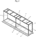
- a hazardous goods container 1 comprises a bottom-side collecting pan arranged in the interior and an upper roof 2, with side walls 3 being provided on one or more sides between the collecting pan and the roof 2.
- the side walls 3 are at three Arranged on the sides, while two sliding gates 6 and 7 are arranged on a fourth side, each of which covers an access opening to the interior of the hazardous goods container 1.
- an outer frame with vertical posts 5 is provided, which support a frame formed from profiles 4 on the roof 2.
- the side walls 3 are formed from panels which have a core made of non-combustible or fire-retardant material, for example corresponding to building material class A1, and sheets are provided on both sides of the core for covering.
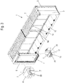
- an inner frame 11 of the hazardous goods container 1 is shown, which is provided within the side walls 3 and the roof 2.
- the inner frame 11 comprises vertical posts 14, which in the upper area support a frame formed from longitudinal profiles 12 and transverse profiles 13, wherein the longitudinal profiles 12 and the transverse profiles 13 can be made of C-shaped folded sheets that are connected to one another with rivets.
- a collecting trough 10 is arranged, which is made from a bent sheet steel, preferably with a sheet thickness between 3 mm to 8 mm, in particular 4 mm to 6 mm.
- strips 16 are provided on which grids can be supported, on which the containers with hazardous substances are then placed.
- FIG 3 the dangerous goods container 1 is shown in section, and only part of the rear sliding gate 7 is visible.
- the sliding gate 7 can be moved in the lower area along a running rail 20 which is supported on a floor section 15.
- the sliding door 7 is framed in a U-shape in the lower area and is arranged between two cover strips 17.
- the sliding door 7 is arranged between cover strips 28 which protrude downward and which cover an upper edge of the sliding door 7.
- the overlap in the vertical direction by the cover strips 17 and 28 can be, for example, at least 5 cm, preferably between 8 cm and 30 cm.
- the cover strips 17 and 28 can have an intumescent material or be made from this in order to be able to reliably close gaps between the sliding door 7 and the cover strips 17 and 28 in the event of a fire.
- a closing side for the sliding gate 7 is shown in detail. It can be seen that next to the running rail 20 on the bottom section 15 there is an upwardly protruding cover strip 17 on the closing side opens at a vertical cover web 32, so that a pocket is formed for one end side of the sliding gate 7.
- a linear damper 22 is provided inside the pocket, which brakes the sliding door 7 during a closing movement shortly before reaching the closed position.
- a plurality of linear dampers 22 can optionally also be arranged distributed over the height.
- a control panel for the lock 21 can be provided on the post 5.
- FIG 5 a lower area of the two sliding gates 6 and 7 is shown, which can be moved via rollers 23 on two running rails 20 which are arranged in different planes. Between the two running rails 20 there is an upwardly protruding cover strip 17, so that the rear sliding door 7 is framed in a U-shape between the cover strip 17 and a side wall 24 of the collecting trough 10.
- each sliding door 6 and 7 is enclosed between two downwardly projecting cover strips 28, the overlap of the cover strips 28 in the vertical direction being preferably between 5 cm to 50 cm, in particular 20 cm to 40 cm.
- the sliding gates 6 and 7 are only guided laterally, while the weight loads are carried by the lower rollers 23 and the running rail 20.
- Each sliding gate 6 and 7 has on the top a guide rail 25 which is U-shaped in cross section and has upwardly projecting legs.
- Guide rollers 26, which are mounted rotatably about an axis 27, are arranged within the guide rail 25.
- the guide rollers 26 are held on the roof 2 of the hazardous goods container 1.
- the guide rail 25 can also be fixed to the roof 2 and serve to guide sliding elements or guide rollers that are attached to one of the sliding gates 6 or 7.
- FIG. 7 the closing side of the two sliding gates 6 and 7 is shown, which must also be sealed in the event of a fire.
- a projection 30, which has a web 31 arranged in the direction of travel, is attached to each sliding gate 6 or 7.
- the hook-shaped projection 30 formed in this way can interlock in the closed position, as shown in FIG Figure 7 is shown. This allows a gap between the two sliding gates 6 and 7 to be sealed on the opening side will.
- the projection 30, like the cover strips 17 and 28, can have an intumescent material or be formed from this.
- FIG 8 a section through the closing side of the sliding gate 7 is shown.
- the vertical closing side is also arranged between two cover webs 32 made of intumescent material, which foam under the action of heat and can close corresponding gaps.
- FIG 9 a further detail of the dangerous goods container 1 is shown.
- a ventilation flap 40 is shown, which is arranged in an open position in order to ventilate the interior of the hazardous goods container 1.
- the ventilation flap 40 is biased into a closed position via a spring (not shown).
- a retaining element 41 made of fusible material is provided, for example made of plastic, which releases the ventilation flap 40 under the action of heat so that it can close under the force of the spring.
- a post 5 of the outer framework is shown, on which a weight 50 is held movably in the vertical direction.
- the weight 50 is connected to a cable 51 which is connected to the sliding gate 6 on the opposite side.
- the weight 50 is lifted so that the cable 51 and the weight 50 act as a spring element which pretensions the sliding door 6 in the closing direction.
- the sliding gate 6 can be held in the open position by a magnet which introduces holding forces on the opening side of the sliding gate 6 in order to prevent the sliding gate 6 from moving in the closing direction.
- the magnet can be designed to be switchable, so that in the event of an accident or fire, the sliding door 6 closes automatically via the spring element.
- a corresponding pre-tensioning and holding mechanism can also be provided for the sliding gate 7.
- the cable 51 can be provided with a rotary damper on a deflection pulley in order to prevent the heavy sliding gate 6 from hitting the post 5.
- one or more linear dampers 22 can be provided, as was shown for the sliding door 7.
- the sliding gates 6 and 7 can be constructed identically and can only be opened in opposite directions.
- two sliding gates 6 and 7 are provided on a longitudinal side of the hazardous goods container 1. It is of course possible to provide only a single sliding gate 6 or 7 and to arrange fixed side walls in the remaining area. In addition, more than two sliding gates 6 or 7 can be arranged on one or more sides of the hazardous goods container 1.
Landscapes
- Engineering & Computer Science (AREA)
- Mechanical Engineering (AREA)
- Buildings Adapted To Withstand Abnormal External Influences (AREA)
- Refuse Receptacles (AREA)
- Respiratory Apparatuses And Protective Means (AREA)
Applications Claiming Priority (1)
| Application Number | Priority Date | Filing Date | Title |
|---|---|---|---|
| DE102020117328.8A DE102020117328A1 (de) | 2020-07-01 | 2020-07-01 | Gefahrgutcontainer |
Publications (4)
| Publication Number | Publication Date |
|---|---|
| EP3932829A2 true EP3932829A2 (fr) | 2022-01-05 |
| EP3932829A3 EP3932829A3 (fr) | 2022-04-06 |
| EP3932829C0 EP3932829C0 (fr) | 2025-07-23 |
| EP3932829B1 EP3932829B1 (fr) | 2025-07-23 |
Family
ID=76283624
Family Applications (1)
| Application Number | Title | Priority Date | Filing Date |
|---|---|---|---|
| EP21177777.6A Active EP3932829B1 (fr) | 2020-07-01 | 2021-06-04 | Récipient pour marchandise dangereuse |
Country Status (2)
| Country | Link |
|---|---|
| EP (1) | EP3932829B1 (fr) |
| DE (1) | DE102020117328A1 (fr) |
Families Citing this family (1)
| Publication number | Priority date | Publication date | Assignee | Title |
|---|---|---|---|---|
| DE102023132632A1 (de) * | 2023-11-23 | 2025-05-28 | Denios Se | Gefahrgutcontainer und Verfahren |
Citations (1)
| Publication number | Priority date | Publication date | Assignee | Title |
|---|---|---|---|---|
| DE202017101249U1 (de) | 2017-03-06 | 2018-06-07 | Denios-Ag | Mindestens eine Tür aufweisender Gefahrgutcontainer, insbesondere Brandschutzcontainer |
Family Cites Families (8)
| Publication number | Priority date | Publication date | Assignee | Title |
|---|---|---|---|---|
| AT288253B (de) * | 1968-07-15 | 1971-02-25 | Talbot Waggonfab | Container für den wahlweisen Transport auf Schienen-, Straßen- oder Wasserfahrzeugen |
| DE2755672A1 (de) * | 1977-12-14 | 1979-06-28 | Dorma Baubeschlag | Schiebetor |
| DE3735968A1 (de) * | 1987-10-23 | 1989-05-03 | Hoermann Belgie Nv | Schiebetor |
| DE4104704A1 (de) * | 1991-02-15 | 1992-08-20 | P & D Systemtechnik Gmbh | Mit einem feuerbestaendigem schiebetor verschliessbarer, vorzugsweise transportabler grossbehaelter |
| JP4458580B2 (ja) * | 1999-08-03 | 2010-04-28 | 日本フルハーフ株式会社 | バン型車両の荷箱等輸送用容器の引戸構造 |
| FR3018788B1 (fr) * | 2014-03-24 | 2016-12-23 | Soc Ind De Prot Incendie | Container de stockage de produits dangereux |
| JP7209443B2 (ja) * | 2018-11-06 | 2023-01-20 | 日本車輌製造株式会社 | 妻引戸を備える鉄道車両 |
| FR3088080B1 (fr) * | 2018-11-07 | 2022-07-15 | Delahaye Ind | Conteneur ou bungalow de stockage de produits dangereux |
-
2020
- 2020-07-01 DE DE102020117328.8A patent/DE102020117328A1/de active Pending
-
2021
- 2021-06-04 EP EP21177777.6A patent/EP3932829B1/fr active Active
Patent Citations (1)
| Publication number | Priority date | Publication date | Assignee | Title |
|---|---|---|---|---|
| DE202017101249U1 (de) | 2017-03-06 | 2018-06-07 | Denios-Ag | Mindestens eine Tür aufweisender Gefahrgutcontainer, insbesondere Brandschutzcontainer |
Also Published As
| Publication number | Publication date |
|---|---|
| DE102020117328A8 (de) | 2022-03-10 |
| EP3932829A3 (fr) | 2022-04-06 |
| DE102020117328A1 (de) | 2022-01-05 |
| EP3932829C0 (fr) | 2025-07-23 |
| EP3932829B1 (fr) | 2025-07-23 |
Similar Documents
| Publication | Publication Date | Title |
|---|---|---|
| EP1250509B1 (fr) | Porte relevable par sections ou porte accordeon | |
| DE19906628A1 (de) | Rauchschutzabschluss | |
| DE4104704A1 (de) | Mit einem feuerbestaendigem schiebetor verschliessbarer, vorzugsweise transportabler grossbehaelter | |
| EP3932829B1 (fr) | Récipient pour marchandise dangereuse | |
| AT394881B (de) | Sektionaltor | |
| DE4435449A1 (de) | Großcontainer | |
| DE2547818C2 (de) | Feuerschutzabschluß für eine Öffnung in Wänden oder Decken, welche von einer Förderanlage durchquert wird | |
| DE8118678U1 (de) | Brandschutz-schiebetor | |
| DE19517241C2 (de) | Vorrichtung zum Abschotten eines Raumes | |
| AT521543B1 (de) | Schutzvorrichtung für Roll- und Sektionaltore | |
| EP2266825B1 (fr) | Véhicule de transport doté d'un dispositif de fermeture de douane | |
| EP4186823B1 (fr) | Sas de transfert de marchandises | |
| DE2420548A1 (de) | Brandwand-abschluss in form von feuerschutzelementen | |
| EP0367883A1 (fr) | Wagon pour le transport des véhicules | |
| CH672000A5 (fr) | ||
| DE9112789U1 (de) | Stellplatz für Abfallcontainer | |
| DE10037329A1 (de) | Sektionalhub- oder Falttor | |
| EP0014949B1 (fr) | Barrage résistant au feu formant cloison dans un canal de câbles | |
| DE102017118275B4 (de) | Torvorrichtung und diese enthaltende Toranordnung | |
| DE3201916C2 (de) | Druckfester Schaltschrank | |
| EP4119761B1 (fr) | Portail à enroulement rapide | |
| DE19725357A1 (de) | Schiebetürschließeinrichtung | |
| EP2594727B1 (fr) | Grille de protection contre les insectes avec un cadre coulissant à fermeture automatique | |
| DE19742752A1 (de) | Abschirm- und/oder Schutzvorrichtung für Gebäudewandöffnungen | |
| EP2372060B1 (fr) | Porte coulissante coupe-feu |
Legal Events
| Date | Code | Title | Description |
|---|---|---|---|
| PUAI | Public reference made under article 153(3) epc to a published international application that has entered the european phase |
Free format text: ORIGINAL CODE: 0009012 |
|
| STAA | Information on the status of an ep patent application or granted ep patent |
Free format text: STATUS: THE APPLICATION HAS BEEN PUBLISHED |
|
| AK | Designated contracting states |
Kind code of ref document: A2 Designated state(s): AL AT BE BG CH CY CZ DE DK EE ES FI FR GB GR HR HU IE IS IT LI LT LU LV MC MK MT NL NO PL PT RO RS SE SI SK SM TR |
|
| PUAL | Search report despatched |
Free format text: ORIGINAL CODE: 0009013 |
|
| AK | Designated contracting states |
Kind code of ref document: A3 Designated state(s): AL AT BE BG CH CY CZ DE DK EE ES FI FR GB GR HR HU IE IS IT LI LT LU LV MC MK MT NL NO PL PT RO RS SE SI SK SM TR |
|
| RIC1 | Information provided on ipc code assigned before grant |
Ipc: E06B 5/16 20060101ALI20220228BHEP Ipc: B65D 90/22 20060101ALI20220228BHEP Ipc: B65D 90/24 20060101ALI20220228BHEP Ipc: B65D 90/00 20060101AFI20220228BHEP |
|
| STAA | Information on the status of an ep patent application or granted ep patent |
Free format text: STATUS: REQUEST FOR EXAMINATION WAS MADE |
|
| 17P | Request for examination filed |
Effective date: 20220830 |
|
| RBV | Designated contracting states (corrected) |
Designated state(s): AL AT BE BG CH CY CZ DE DK EE ES FI FR GB GR HR HU IE IS IT LI LT LU LV MC MK MT NL NO PL PT RO RS SE SI SK SM TR |
|
| STAA | Information on the status of an ep patent application or granted ep patent |
Free format text: STATUS: EXAMINATION IS IN PROGRESS |
|
| 17Q | First examination report despatched |
Effective date: 20230922 |
|
| GRAP | Despatch of communication of intention to grant a patent |
Free format text: ORIGINAL CODE: EPIDOSNIGR1 |
|
| STAA | Information on the status of an ep patent application or granted ep patent |
Free format text: STATUS: GRANT OF PATENT IS INTENDED |
|
| RIC1 | Information provided on ipc code assigned before grant |
Ipc: E06B 5/16 20060101ALN20250210BHEP Ipc: E06B 3/46 20060101ALN20250210BHEP Ipc: B65D 90/24 20060101ALI20250210BHEP Ipc: B65D 90/22 20060101ALI20250210BHEP Ipc: B65D 90/00 20060101AFI20250210BHEP |
|
| INTG | Intention to grant announced |
Effective date: 20250313 |
|
| GRAS | Grant fee paid |
Free format text: ORIGINAL CODE: EPIDOSNIGR3 |
|
| GRAA | (expected) grant |
Free format text: ORIGINAL CODE: 0009210 |
|
| STAA | Information on the status of an ep patent application or granted ep patent |
Free format text: STATUS: THE PATENT HAS BEEN GRANTED |
|
| AK | Designated contracting states |
Kind code of ref document: B1 Designated state(s): AL AT BE BG CH CY CZ DE DK EE ES FI FR GB GR HR HU IE IS IT LI LT LU LV MC MK MT NL NO PL PT RO RS SE SI SK SM TR |
|
| REG | Reference to a national code |
Ref country code: GB Ref legal event code: FG4D Free format text: NOT ENGLISH |
|
| REG | Reference to a national code |
Ref country code: CH Ref legal event code: EP |
|
| REG | Reference to a national code |
Ref country code: DE Ref legal event code: R096 Ref document number: 502021008053 Country of ref document: DE Ref country code: DE Ref legal event code: R081 Ref document number: 502021008053 Country of ref document: DE Owner name: DENIOS SE, DE Free format text: FORMER OWNER: ANMELDERANGABEN UNKLAR / UNVOLLSTAENDIG, 80297 MUENCHEN, DE |
|
| REG | Reference to a national code |
Ref country code: IE Ref legal event code: FG4D Free format text: LANGUAGE OF EP DOCUMENT: GERMAN |
|
| RAP4 | Party data changed (patent owner data changed or rights of a patent transferred) |
Owner name: DENIOS SE |
|
| U01 | Request for unitary effect filed |
Effective date: 20250821 |
|
| U07 | Unitary effect registered |
Designated state(s): AT BE BG DE DK EE FI FR IT LT LU LV MT NL PT RO SE SI Effective date: 20250828 |
|
| PG25 | Lapsed in a contracting state [announced via postgrant information from national office to epo] |
Ref country code: IS Free format text: LAPSE BECAUSE OF FAILURE TO SUBMIT A TRANSLATION OF THE DESCRIPTION OR TO PAY THE FEE WITHIN THE PRESCRIBED TIME-LIMIT Effective date: 20251123 |
|
| PG25 | Lapsed in a contracting state [announced via postgrant information from national office to epo] |
Ref country code: NO Free format text: LAPSE BECAUSE OF FAILURE TO SUBMIT A TRANSLATION OF THE DESCRIPTION OR TO PAY THE FEE WITHIN THE PRESCRIBED TIME-LIMIT Effective date: 20251023 |
|
| PG25 | Lapsed in a contracting state [announced via postgrant information from national office to epo] |
Ref country code: HR Free format text: LAPSE BECAUSE OF FAILURE TO SUBMIT A TRANSLATION OF THE DESCRIPTION OR TO PAY THE FEE WITHIN THE PRESCRIBED TIME-LIMIT Effective date: 20250723 |
|
| PG25 | Lapsed in a contracting state [announced via postgrant information from national office to epo] |
Ref country code: GR Free format text: LAPSE BECAUSE OF FAILURE TO SUBMIT A TRANSLATION OF THE DESCRIPTION OR TO PAY THE FEE WITHIN THE PRESCRIBED TIME-LIMIT Effective date: 20251024 |
|
| PG25 | Lapsed in a contracting state [announced via postgrant information from national office to epo] |
Ref country code: PL Free format text: LAPSE BECAUSE OF FAILURE TO SUBMIT A TRANSLATION OF THE DESCRIPTION OR TO PAY THE FEE WITHIN THE PRESCRIBED TIME-LIMIT Effective date: 20250723 |
|
| PG25 | Lapsed in a contracting state [announced via postgrant information from national office to epo] |
Ref country code: RS Free format text: LAPSE BECAUSE OF FAILURE TO SUBMIT A TRANSLATION OF THE DESCRIPTION OR TO PAY THE FEE WITHIN THE PRESCRIBED TIME-LIMIT Effective date: 20251023 |
|
| PG25 | Lapsed in a contracting state [announced via postgrant information from national office to epo] |
Ref country code: ES Free format text: LAPSE BECAUSE OF FAILURE TO SUBMIT A TRANSLATION OF THE DESCRIPTION OR TO PAY THE FEE WITHIN THE PRESCRIBED TIME-LIMIT Effective date: 20250723 |