EP3934864B1 - Refroidissement à trajets multiples pour des systèmes robotiques - Google Patents
Refroidissement à trajets multiples pour des systèmes robotiques Download PDFInfo
- Publication number
- EP3934864B1 EP3934864B1 EP20766797.3A EP20766797A EP3934864B1 EP 3934864 B1 EP3934864 B1 EP 3934864B1 EP 20766797 A EP20766797 A EP 20766797A EP 3934864 B1 EP3934864 B1 EP 3934864B1
- Authority
- EP
- European Patent Office
- Prior art keywords
- base
- bracket
- heat
- heat sink
- flange
- Prior art date
- Legal status (The legal status is an assumption and is not a legal conclusion. Google has not performed a legal analysis and makes no representation as to the accuracy of the status listed.)
- Active
Links
Images




Classifications
-
- B—PERFORMING OPERATIONS; TRANSPORTING
- B25—HAND TOOLS; PORTABLE POWER-DRIVEN TOOLS; MANIPULATORS
- B25J—MANIPULATORS; CHAMBERS PROVIDED WITH MANIPULATION DEVICES
- B25J19/00—Accessories fitted to manipulators, e.g. for monitoring, for viewing; Safety devices combined with or specially adapted for use in connection with manipulators
- B25J19/0054—Cooling means
-
- B—PERFORMING OPERATIONS; TRANSPORTING
- B25—HAND TOOLS; PORTABLE POWER-DRIVEN TOOLS; MANIPULATORS
- B25J—MANIPULATORS; CHAMBERS PROVIDED WITH MANIPULATION DEVICES
- B25J9/00—Program-controlled manipulators
- B25J9/02—Program-controlled manipulators characterised by movement of the arms, e.g. cartesian coordinate type
- B25J9/04—Program-controlled manipulators characterised by movement of the arms, e.g. cartesian coordinate type by rotating at least one arm, excluding the head movement itself, e.g. cylindrical coordinate type or polar coordinate type
- B25J9/041—Cylindrical coordinate type
- B25J9/042—Cylindrical coordinate type comprising an articulated arm
-
- B—PERFORMING OPERATIONS; TRANSPORTING
- B25—HAND TOOLS; PORTABLE POWER-DRIVEN TOOLS; MANIPULATORS
- B25J—MANIPULATORS; CHAMBERS PROVIDED WITH MANIPULATION DEVICES
- B25J9/00—Program-controlled manipulators
- B25J9/02—Program-controlled manipulators characterised by movement of the arms, e.g. cartesian coordinate type
- B25J9/04—Program-controlled manipulators characterised by movement of the arms, e.g. cartesian coordinate type by rotating at least one arm, excluding the head movement itself, e.g. cylindrical coordinate type or polar coordinate type
- B25J9/041—Cylindrical coordinate type
- B25J9/042—Cylindrical coordinate type comprising an articulated arm
- B25J9/044—Cylindrical coordinate type comprising an articulated arm with forearm providing vertical linear movement
-
- H—ELECTRICITY
- H05—ELECTRIC TECHNIQUES NOT OTHERWISE PROVIDED FOR
- H05K—PRINTED CIRCUITS; CASINGS OR CONSTRUCTIONAL DETAILS OF ELECTRIC APPARATUS; MANUFACTURE OF ASSEMBLAGES OF ELECTRICAL COMPONENTS
- H05K7/00—Constructional details common to different types of electric apparatus
- H05K7/20—Modifications to facilitate cooling, ventilating, or heating
- H05K7/2039—Modifications to facilitate cooling, ventilating, or heating characterised by the heat transfer by conduction from the heat generating element to a dissipating body
- H05K7/20409—Outer radiating structures on heat dissipating housings, e.g. fins integrated with the housing
Definitions
- This application relates to robotic systems, and in particular, to multi-path cooling for robotic arms, as well as related systems and methods.
- Robotic systems including robotic arms, may be used to perform various tasks, and are particularly common in automation.
- Robotic arms typically comprise a plurality of links connected by one or more joints.
- the one or more joints are driven by various types of actuators (e.g., electric motors, hydraulics, etc.) to control articulation of the robotic arm to position an end effector that is configured to perform a task.
- actuators e.g., electric motors, hydraulics, etc.
- a method for dissipating heat in a robotic system includes mounting a heat generating component on a bracket within a base of a robotic arm, the bracket being thermally conductive; attaching the bracket to a first heat sink positioned on a first side of the base to form a first thermally conductive path configured to dissipate heat from the heat generating component; and contacting a thermal pad positioned on the bracket to a second heat sink positioned on a second side of the base to form a second thermally conductive path configured to dissipate heat from the heat generating component.
- the method can include one or more of the following features in any combination: (a) wherein contacting the thermal pad comprises attaching a rear portion of the housing to a front portion of the housing, wherein the first heat sink is disposed on the rear portion of the housing and the bracket is connected to the rear portion of the housing, and wherein the second heat sink is disposed on the front portion of the housing; (b) wherein the heat generating component comprises an amplifier, and wherein mounting the heat generating component on the bracket comprises mounting the amplifier on the bracket such that a longitudinal axis of the amplifier extends in a generally horizontal direction; (c) wherein the first heat sink comprises one of more fins formed on the first side of the base; and/or (d) wherein the second heat sink comprises one of more fins formed on the second side of the base.
- the base 12 can be configured to support the other portions of the robotic system 10, such as the first link 14, the second link 16, and the end effector 18. As illustrated, the robotic arm is supported by and extends from the base 12. In some embodiments, the base 12 includes an integrated controller for operating the robotic arm.
- the first link 14 is connected to the base 12 by a first rotational joint 20.
- the first rotational joint 20 allows the first link 14 to rotate or articulate relative to the base 12. In the illustrated embodiment, the first link 14 rotates relative to the base 12 about a first axis of rotation 24.
- rotation of the first link 14 relative to the base 12 may be controlled through the execution of one or more sequences of instructions (i.e., software) and/or by customized hardware (e.g., application-specific integrated circuit(s), field-programmable gate array(s), etc.).
- instructions i.e., software
- customized hardware e.g., application-specific integrated circuit(s), field-programmable gate array(s), etc.
- One or more motors can be used to drive rotation or articulation of the first rotational joint 20.
- the one or more motors can be, for example, electric motors.
- the motors can be positioned in the base 12 and/or the first link 14.
- the one or more motors can be connected to one or more amplifiers 44 (see FIGS. 3 and 4 ) that are configured to drive the one or more motors.
- the amplifiers 44 can be controlled, for example, by a motor controller. As will be described more fully below, the amplifiers 44 can be positioned within the base 12.
- the amplifiers 44 may generate heat that may need to be dissipated for sustained use of the robotic system 10.
- the multi-path cooling arrangements described below can be used to dissipate the heat generated by the amplifiers 44, for example.
- the multi-path cooling arrangements can also be configured to dissipate heat generated by other components of the robotic system 10, such as processors positioned within the base 12, for example.
- the second link 16 can be connected to the first link 14 by a second rotational joint 22.
- the second rotational joint 22 allows the second link 16 to rotate or articulate relative to the first link 14.
- the second link 16 rotates relative to the first link 14 about a second axis of rotation 26.
- rotation of the second link 16 relative to the first link 14 may be controlled or limited by software or customized hardware.
- One or more motors (not illustrated) can be used to drive rotation or articulation of the second rotational joint 22 as described above with reference to the first rotational joint 20.
- the one or more motors can be connected to one or more amplifiers 44, which can be positioned within the base 12.
- the multi-path cooling arrangements described below can be used to dissipate the heat generated by the amplifiers 44 associated with the motors of the second rotational joint 22 or other heat generating components within the base 12.
- the base 12, first link 14, and second link 16 are arranged to form a selective compliance assembly robot arm (SCARA).
- SCARA selective compliance assembly robot arm
- the multi-path cooling arrangements described herein may be configured for use with SCARAs and may also be configured for use with other types of robotic arms (e.g., non-SCARA) and other robotic systems.
- the robotic system 10 includes an end effector 18.
- the end effector 18 is positionable by rotating or articulating the first and/or second links 14, 16 about the first and/or second rotational axes 24, 26.
- the end effector 18 may be driven by one or more motors.
- the one or motors can be driven by amplifiers 44, which can be positioned within the base 12.
- the end effector 18 can be configured to perform various tasks as will be apparent to those of ordinary skill in the art.
- the base 12 may house (e.g., partially or fully enclose) many of the electronic components of the robotic system 10.
- the base 12 houses an integrated controller.
- the integrated controller may comprise one or more components configured to control or allow control of the robotic arm.
- integrating the controller into the base 12 adds additional components to the base 12. This causes the base 12 to be more full (less empty space) and generates more heat.
- the multi-path cooling arrangements described herein can address these challenges, allowing for the use of a controller integrated into the base 12, while still sufficiently managing heat.
- the controller which may comprise one or more processor boards, is mounted directly to the rear heat sink (e.g., the first heat sink 28 or the second heat sink 30), displacing the amplifiers 44 to the position shown in FIGS. 3 and 4 (e.g., on the bracket 46). In this position, the amplifiers 44, which generate heat, are not closely positioned to a heat sink. Thus, it may be difficult to dissipate heat from the amplifiers 44.
- the multi-path cooling arrangements described herein can address this difficulty as discussed below.
- the amplifiers 44 can be mounted directly to a heat sink (e.g., the first or second heat sinks 28, 30), displaying the controller to a position within the base that does not directly contact a heat sink. In this arrangement, the multi-path cooling arrangement described herein can be used to dissipate heat from the controller.
- the base 12 may house the integrated controller, the amplifiers 44, and motor controllers associated with motion of the first link 14, the second link 16, and the end effector 18.
- Other components can also be positioned within the base 12. Often, these electronic components generate heat that must be dissipated in order to prevent the robotic system 10 from overheating. In many instances, it can be beneficial to position many of these heat generating components of the robotic system 10 within the base 12 because, for example, this may produce a space-efficient design, maximize the stability of the robotic system 10, and/or simplify wiring of the robotic system 10. However, grouping heat generating components within the base 12 may pose some challenges.
- grouping heat generating components within the base 12 may increase the total amount of heat that needs to be dissipated, while minimizing the space with which do so.
- the base 12 may be water resistant, water tight, or tightly sealed such that natural convection of heat within or from the base 12 is limited.
- the multi-path cooling arrangements described herein may resolve or aid in resolving these challenges.
- multi-path heat generated by the heat generating components has more than one path (e.g., more than one thermally conductive path) by which it can be dissipated.
- the base 12 can include a first heat sink 28 and a second heat sink 30.
- a multi-path cooling arrangement can provide a first thermal path for dissipating heat to the first heat sink 28 and a second thermal path for dissipating heat to the second heat sink 30.
- the first heat sink 28 is positioned on a rear side or portion 32 of the base 12, and the second heat sink 30 is positioned on a front side or portion 34 of the base 12.
- the rear side or portion 32 is opposite the front side or portion 34.
- Other positions of the first heat sink 28 and the second heat sink 30 are also possible.
- the first heat sink 28 and the second heat sink 30 can be reversed such that the first heat sink 28 is positioned on the front side or portion 34 and the second heat sink 30 is positioned on the rear side or portion 32.
- the first heat sink 28 and the second heat sink 30 can be positioned on a right side or portion 36 and a left side or portion 38, respectively (or vice versa).
- one of the first heat sink 28 and the second heat sink 30 can be positioned on the rear side or portion 32 or the front side or portion 34 and the other of the first heat sink 28 and the second heat sink 30 can be positioned on the right side or portion 36 or the left side or portion 38. In some embodiments, both the first heat sink 28 and the second heat sink 30 can be positioned on the same side or portion. In some embodiments, one or both of the first heat sink 28 and the second heat sink 30 can be positioned on a top side or portion 40 of the base 12.
- heat sink is used broadly to denote any structure that is configured to dissipate heat.
- a heat sink comprises one or more fins 42 configured to provide surface areas for dissipating heat.
- Other structures for the heat sinks are also possible.
- a heat sink can comprise a wall, such as a wall of the base 12.
- a heat sink is integrally formed with or attached to the base 12.
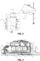
- FIGS. 3 and 4 are cross-sectional views of a portion of the robotic system 10. These figures illustrate an example multi-path cooling arrangement that includes paths to the first heat sink 28 and the second heat sink 30.
- the multi-path cooling arrangement is configured to dissipate heat from one or more amplifiers 44 positioned within the base 12. As mentioned above, the amplifiers 44 may be configured to drive one or more motors associated with rotation of the first rotational joint 20, the second rotational joint 22, and/or the end effector 18. It will be appreciated that the multi-path cooling system may also be used to dissipate heat from other heat generating components, such as processors or controllers, for example.
- the amplifiers 44 can be mounted on a bracket 46.
- the amplifiers 44 can be mounted on the bracket 46 in a manner that allows thermal communication between the bracket 46 and the amplifiers 44.
- the amplifiers 44 are in direct physical contact with the bracket 46 such that heat generated by the amplifiers 44 can be directly conducted to the bracket 46.
- the bracket 46 may comprise a thermally conductive material, such as aluminum, although other thermally conductive materials may also be used.
- the bracket 46 may be configured in size and shape so as to provide an effective conductive pathway.
- the bracket may comprise a thickness of at least 2 mm, at least 3 mm, at least 4 mm, at least 5 mm, at least 6 mm, at least 7 mm, at least 8 mm, at least 9 mm, at least 10 mm, or thicker such that it can adequately dissipate heat from the amplifiers 44 through conduction.
- the bracket is approximately 6.3 mm thick.
- the bracket 46 may comprise a base plate 48, a first flange 50, and a second flange 52.
- the base plate 48 extends along the bottom of the base 12 in a horizontal direction, for example, generally parallel to a support surface (such as the ground) on which the base 12 is placed.
- the amplifiers 44 can be mounted on the base plate 48 between the first flange 50 and the second flange 52.
- the first flange 50 can be positioned on a first side of the base plate 48.
- the first flange 50 can extend from the base plate 48 at an angle.
- the angle of the first flange 50 relative to the base plate 48 is about 90 degrees, although this need not be the case in all embodiments (e.g., the angle of the first flange can be less than or greater than 90 degrees depending on the application).
- the second flange 52 can be positioned on a second side of the base plate 48. In some embodiments, the second side of the base plate 48 is opposite the first side of the base plate 48 such that the first flange 50 and the second flange 52 are on opposite sides or ends of the base plate 48.
- the second flange 52 can extend from the base plate 48 at an angle. In the illustrated embodiment, the angle of the second flange 52 relative to the base plate 48 is about 90 degrees, although this need not be the case in all embodiments.
- one or both of the first flange 50 and the second flange 52 can be the same thickness as the base plate 48. In some embodiments, one or both of the first flange 50 and the second flange 52 can be slightly thinner than the base plate 48. For example, in an embodiment where the base plate 48 is about 6.3 mm thick, one or both of the first flange 50 and the second flange 52 can be about 5.3 mm thick. This can be because the bracket 46 can be machined in these areas. Machining one or both of the first flange 50 and the second flange 52 can ensure contact between the flanges and the base 12, which as described below can provide thermal communication therebetween.
- the first flange 50 can be attached to the rear side or portion 32 of the base 12, as shown in FIGS. 3 and 4 .
- the first flange 50 is attached to the rear side or portion 32 of the base 12 with one or more mechanical fasteners 54 as shown.
- the first flange 50 can be bonded, welded, or integrally formed with the rear side or portion 32 of the base 12. Accordingly, the first flange 50 can be in contact with the rear side or portion 32 of the base 12 so as to allow thermal conduction between the two.
- the first heat sink 28 can be included on the rear side or portion 32 of the base 12.
- the first flange 50 can be in thermal communication with the first heat sink 28.
- the second flange 52 of the bracket 46 can be positioned so as to contact the front side or portion 34 of the base 12, as shown in FIGS. 3 and 4 .
- the second flange 52 can include a thermal pad 56 positioned on a face thereof that contacts the contact the front side or portion 34 of the base 12.
- the thermal pad 56 can be configured to improve or maximize conduction from the second flange 52 to the front side or portion 34 of the base 12.
- the thermal pad 56 can fill any gaps between the second flange 52 and the base 12 so as to facilitate or ensure direct contact therebetween.
- the thermal pad 56 can be adhesively attached to the face of the second flange 52, or can be attached in other ways.
- the thermal pad 56 is compliant such that it can be pressed between the second flange 52 and the front side or portion 34 of the base 12 to ensure or facilitate contact between the two.
- the thermal pad 56 may comprise a thermally conductive material.
- the thermal pad is about 1 mm, about 2 mm, about 3 mm, about 4 mm, about 5 mm, about 6 mm, about 7 mm, about 8 mm or thicker. In one example, the thermal pad 56 is about 3.2 mm thick.
- the second heat sink 30 can be included on the front side or portion 34 of the base 12.
- the second flange 52 can be in thermal communication with the second heat sink 30 through the thermal pad 56.
- the thermal pad 56 can be omitted and the second flange 52 can directly contact the front side or portion 34 of the base 12. In some embodiments, the thermal pad 56 is attached to the inner surface of the front side or portion 34 rather than to the second flange 52.
- the second flange 52 of the bracket 46 is not attached to the front side or portion 34 of the base 12. This may allow the base 12 to be configured such that the rear side or portion 32 is removable from the front side or portion 34 of the base 12 as shown in FIG. 5 , which is described below. In other embodiments, the second flange 52 of the bracket 46 may be attached to the front side or portion 34 of the base 12 similar to how the first flange 50 of the bracket 46 is attached the rear side or portion 32 of the base 12.
- the multi-path cooling arrangement thus includes at least two thermal paths for dissipating heat from the amplifiers 44. These paths are illustrated with dotted lines in the figures.
- a first thermal path 58 allows heat to be conducted from the amplifiers 44 into the base plate 48 of the bracket 46. The heat is conducted through the bracket 46 to the first flange 50 and into the rear side or portion 32 where it can be dissipated by the first heat sink 28.
- a second thermal path 60 allows heat to be conducted from the amplifiers 44 into the base plate of the bracket 46. The heat is then conducted through the bracket 46 to the second flange 52 and into the front side or portion 34 where it can be dissipated by the second heat sink 30.
- Such a multi-path cooling arrangement may advantageously improve heat dissipation for the amplifiers 44.
- the multi-path cooling arrangement may provide other or additional benefits as well.
- the amplifiers 44 extend generally along a longitudinal axis 62.
- the amplifiers 44 may generally comprise a length (measured along the longitudinal axis 62) that is longer than their width (measured transverse to the longitudinal axis 62).
- to minimize the overall size of the base 12 it may be beneficial to arrange the amplifiers as shown in FIG. 4 , such that the longitudinal axis 62 extends in a generally horizontal direction. While this arrangement may minimize the overall size of the base 12, it may not be advantageous from a thermal perspective.
- the multi-path cooling arrangements described herein can be allow the amplifiers to be arranged such that the longitudinal axis 62 extends in a generally horizontal direction while still providing sufficient heat dissipation.
- FIG. 5 is a side view of a base 12 of the robotic system 10 of FIG. 1 and illustrates that, in some embodiments, the rear side or portion 32 of the base 12 can be removed from the front side or portion 34 of the base 12. This can be done to allow access to the interior of the base 12 for, for example, assembly, maintenance, repairs, etc.
- the bracket 46 and amplifiers 44 mounted thereto can be removed as well. This may be because, as described above, the bracket 46 is attached to the rear side or portion 32 as described above.
- the first flange 50 of the bracket 46 can be attached to the rear side or portion 32.
- the bracket 46 and amplifiers 44 can be removed as well.
- bracket 46 can be removed with the rear side or portion 32 because the bracket 46 may not, in some embodiments, be attached to the front side or portion 34. Rather, as described above with reference to FIGS. 3 and 4 , the bracket 46 only contacts the front side or portion 34 without being attached thereto. For example, as described above, the second flange 52 of the bracket 46 is in contact with the front side or portion 34 through the thermal pad 56 when assembled. Thus, the bracket 46 and amplifiers 44 can easily be removed from the front side or portion 34 as shown in FIG. 5 .
- the rear side or portion 34 can be brought back together with the front side or portion 34 to form the base 12 as an enclosure (as shown, for example, in FIGS. 1 and 2 ).
- the second flange 52 of the bracket 46 contacts the front side or portion 34 through the thermal pad 56 to establish the second thermal path to the second heat sink 30 on the front side or portion 34.
- the thermal pad 56 may ensure or facilitate strong thermal contact between the second flange 52 and the front side or portion 34.
- the first and/or second flanges 50, 52 of the bracket 46 can be configured in size and shape to provide sufficient contact between the flanges 50, 52 and the corresponding portions 32, 34 of the base 12 so as to provide an effective thermally conductive path.
- one or both of the flanges 50, 52 are configured with a surface area of at least 2 square inches, at least 3 square inches, at least 4 square inches, at least 5 square inches, or more so as to provide sufficient contact between the flanges 50, 52 and the base 12 to conduct heat.
- the first and/or second flange has a contact surface are of about 4 inches with the base 12.
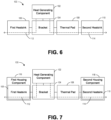
- FIG. 6 is a block diagram illustrating a system 100 including a multi-path cooling arrangement according to one embodiment.
- the system 100 includes a heat generating component 102, a bracket 104, a first heat sink 106, a thermal pad 108, and a second heat sink 110 arranged so as to provide a first thermal path 112 and a second thermal path 114.
- the system 100 is a robotic system, such as a robotic arm.
- the heat generating component 102 can be any component which generates heat.
- the system 100 can be configured to dissipate the heat generated by the heat generating component 102 along the first thermal path 112 and the second thermal path 114.
- the heat generating component is an amplifier (e.g., amplifier 44 described above), although this need not be the case in all embodiments.
- the heat generating component 102 could be a processor, an integrated circuit, a motor control, a motor, a data storage device, and/or a memory, among many others.
- the heat generating component 102 can be mounted on a bracket 104 or other thermally conductive structure configured to support the heat generating component 102.
- the bracket 104 can be arranged so that heat generated by the heat generating component 102 is communicated to the bracket 104.
- the heat can be communicated into the bracket 104 by conduction, for example.
- the heat generating component 102 can be in physical contact with the bracket 104, either directly or indirectly through another structure (such as, e.g., a thermal pad, thermal paste, an additional thermally conductive bracket, etc.).
- the bracket 104 can comprise a thermally conductive material, such as aluminum, silicon carbide, tungsten, and/or others.
- the bracket 104 can be attached, either directly or indirectly to a first heat sink 106 as shown in FIG. 6 .
- the bracket 104 is attached to the first heat sink 106 with mechanical fasteners, although other joining methods are also possible.
- the first heat sink 106 can be positioned on (or be part of) a base, enclosure, or other structure. As shown, a first thermal path 112 is formed from the heat generating component 102, through the bracket 104, and to the first heat sink 106.
- a thermal pad 108 can be attached to the bracket 104.
- the thermal pad 108 can comprise a thermally conductive material.
- the thermal pad 108 and bracket 104 can be arranged so as to contact a second heat sink 110.
- the bracket 104 is not attached to the second heat sink 110. Accordingly, in FIG. 6 , a dashed line has been used between the thermal pad 108 and the second heat sink 110 to indicate that these features may, in some embodiments, be in contact with each other, while not mechanically connected to each other.
- the second heat sink 110 can be positioned on (or be part of) a base, enclosure, or other structure.
- a second thermal path 114 is formed from the heat generating component 102, through the bracket 104 and thermal pad 108, and to the second heat sink 110.
- the thermal pad 108 may be omitted and the bracket 104 may contact the second heat sink 110 directly.
- the system 100 includes a multi-path cooling arrangement that includes the first thermal path 112 and the second thermal path 114 for dissipating heat from the heat generating component 102 to the first heat sink 106 and the second heat sink 110, respectively.
- FIG. 7 is a block diagram illustrating another embodiment of the system 100.
- the first heat sink 106 is positioned on a first housing component 116 and the second heat sink 110 is positioned on a second housing component 118.
- the first and second housing components 116, 118 can be configured to form an enclosure that partially or fully encloses the heat generating component.
- the first and second housing components 116, 118 can be detached from each other to allow access to the interior of the enclosure.
- the bracket 104 can be attached to the first heat sink 106, which is formed on the first housing component 116.
- the bracket 104 and heat generating component 102 can be removed with it.
- the bracket 104 may contact the second heat sink 110 through the thermal pad 108.
- the first thermal path 112 is formed from the heat generating component 102, through the bracket 104, and to the first heat sink 106 on the first housing component 116.
- the second thermal path 114 is formed from the heat generating component 102, through the bracket 104 and thermal pad 108, and to the second heat sink 110 on the second housing component 118.
- FIG. 8 is a flowchart illustrating a method 200 for dissipating heat in a robotic system according to one embodiment.
- the method begins at block 202, at which a heat generating component is mounted on a thermally conductive bracket.
- the bracket is positioned with a base of a robotic system, such as a robotic arm.
- the heat generating component can be mounted on the bracket such that heat generated by the heat generating component is conducted into the bracket.
- the heat generating component is an amplifier as described above, although the method 200 is useful with other types of heat generating components as well.
- the bracket is attached to a first heat sink to form a first thermally conductive path configured to dissipate heat from the heat generating component.
- the heat sink is positioned on a first side of the base.
- the heat sink comprises one or more fins configured to dissipate heat.
- the bracket is mechanically fastened to the first heat sink. Other joining methods may also be used.
- a thermal pad positioned on the bracket is contacted to a second heat sink to form a second thermally conductive path configured to dissipate heat from the heat generating component.
- the heat sink is positioned on a second side of the base.
- the heat sink comprises one or more fins configured to dissipate heat.
- contacting the thermal pad to the second heat sink comprises attaching a rear portion of the housing to a front portion of the housing.
- the first heat sink can be positioned on the rear portion of the housing and the bracket can be connected to the rear portion of the housing.
- the second heat sink can be disposed on the front portion of the housing.
- top, bottom, side, up, down, inward, outward, etc. are generally used with reference to the orientation shown in the figures and are not intended to be limiting.
- the top surface described above can refer to a bottom surface or a side surface.
- features described on the top surface may be included on a bottom surface, a side surface, or any other surface.
Landscapes
- Engineering & Computer Science (AREA)
- Robotics (AREA)
- Mechanical Engineering (AREA)
- Physics & Mathematics (AREA)
- Thermal Sciences (AREA)
- Microelectronics & Electronic Packaging (AREA)
- Manipulator (AREA)
- Cooling Or The Like Of Electrical Apparatus (AREA)
Claims (14)
- Système robotique (10) comprenant :
une base (12) supportant une ou plusieurs liaisons articulées (14, 16), la base (12) comprenant :une partie avant comprenant une paroi avant ;une partie arrière fixée de manière amovible à la partie avant et comprenant une paroi arrière ; etun support (46, 104) supportant un composant générateur de chaleur (102), un premier côté du support (46, 104) étant fixé à la paroi arrière de la partie arrière de la base (12) pour former un premier trajet thermiquement conducteur qui, lors de l'utilisation, dissipe la chaleur en provenance du composant générateur de chaleur (102) ;dans lequel,le système robotique (10) est caractérisé en ce qu'il comprend en outre :
un tampon thermique (56, 108) fixé à un second côté du support (46, 104), le tampon thermique (56, 108) entrant en contact avec la paroi avant de la base (12) pour former un second trajet thermiquement conducteur qui, en cours d'utilisation, dissipe la chaleur en provenance du composant générateur de chaleur (102). - Système selon la revendication 1, dans lequel la partie arrière est reliée de manière amovible à la partie avant.
- Système selon la revendication 1, dans lequel le composant générateur de chaleur (102) comprend un amplificateur (44).
- Système selon la revendication 3, dans lequel l'amplificateur (44) est monté sur le support (46, 104) de telle sorte qu'un axe longitudinal de l'amplificateur (44) s'étende dans une direction sensiblement horizontale.
- Système selon la revendication 1, dans lequel au moins l'une de la paroi avant de la partie avant et de la paroi arrière de la partie arrière comprend une ou plusieurs ailettes (42) configurées pour dissiper la chaleur.
- Système selon la revendication 1, dans lequel un contrôleur intégré est positionné à l'intérieur de la base (12) et en contact thermique avec un dissipateur thermique (28, 30) positionné sur l'une de la partie avant et de la partie arrière de la base (12).
- Système selon la revendication 1, dans lequel le support (46, 104) comprend :une première bride (50) reliée à la paroi arrière de la partie arrière ;une seconde bride (52), dans lequel le tampon thermique (56, 108) est positionné sur une surface extérieure de la première bride (50) de manière à entrer en contact avec la paroi avant de la partie avant ; etune plaque (48) s'étendant entre la première bride (50) et la seconde bride (52), dans lequel le composant générateur de chaleur (102) est monté sur la plaque (48).
- Système selon la revendication 7, dans lequel la première bride (50) et la seconde bride (52) s'étendent dans une direction sensiblement verticale, et la plaque (48) s'étend dans une direction sensiblement horizontale.
- Système selon la revendication 1, dans lequel la base (12) est sensiblement étanche.
- Procédé destiné à la dissipation de chaleur dans un système robotique (10), le procédé comprenant :le montage d'un composant générateur de chaleur (102) sur un support (46, 104) à l'intérieur d'une base (12) d'un bras robotique, le support (46, 104) étant conducteur de chaleur ; etla fixation du support (46, 104) à un premier dissipateur thermique (28) positionné sur un premier côté de la base (12) pour former un premier trajet thermiquement conducteur configuré pour dissiper la chaleur en provenance du composant générateur de chaleur (102), dans lequel,le procédé est caractérisé en ce qu'il comprend en outre :
la mise en contact d'un tampon thermique (56, 108) positionné sur le support (46, 104) avec un second dissipateur thermique (30) positionné sur un second côté de la base (12) pour former un second trajet thermiquement conducteur configuré pour dissiper la chaleur en provenance du composant générateur de chaleur (102). - Procédé selon la revendication 10, dans lequel la mise en contact du tampon thermique (56, 108) comprend la fixation d'une partie arrière d'un boîtier à une partie avant du boîtier, dans lequel le premier dissipateur thermique (28) est disposé sur la partie arrière du boîtier et le support (46, 104) est connecté à la partie arrière du boîtier, et dans lequel le second dissipateur thermique (30) est disposé sur la partie avant du boîtier.
- Procédé selon la revendication 10, dans lequel le composant générateur de chaleur (102) comprend un amplificateur (44), et dans lequel le montage du composant générateur de chaleur (102) sur le support (46, 104) comprend le montage de l'amplificateur (44) sur le support (46, 104) de telle sorte qu'un axe longitudinal de l'amplificateur (44) s'étende dans une direction globalement horizontale.
- Procédé selon la revendication 10, dans lequel le premier dissipateur thermique (28) comprend une ou plusieurs ailettes (42) formées sur le premier côté de la base (12).
- Procédé selon la revendication 10, dans lequel le second dissipateur thermique (30) comprend une ou plusieurs ailettes (42) formées sur le second côté de la base (12).
Priority Applications (1)
| Application Number | Priority Date | Filing Date | Title |
|---|---|---|---|
| EP24206272.7A EP4467295A3 (fr) | 2019-03-04 | 2020-02-28 | Refroidissement à trajets multiples pour des systèmes robotiques |
Applications Claiming Priority (2)
| Application Number | Priority Date | Filing Date | Title |
|---|---|---|---|
| US201962813505P | 2019-03-04 | 2019-03-04 | |
| PCT/US2020/020373 WO2020180676A1 (fr) | 2019-03-04 | 2020-02-28 | Refroidissement à trajets multiples pour des systèmes robotiques |
Related Child Applications (2)
| Application Number | Title | Priority Date | Filing Date |
|---|---|---|---|
| EP24206272.7A Division EP4467295A3 (fr) | 2019-03-04 | 2020-02-28 | Refroidissement à trajets multiples pour des systèmes robotiques |
| EP24206272.7A Division-Into EP4467295A3 (fr) | 2019-03-04 | 2020-02-28 | Refroidissement à trajets multiples pour des systèmes robotiques |
Publications (3)
| Publication Number | Publication Date |
|---|---|
| EP3934864A1 EP3934864A1 (fr) | 2022-01-12 |
| EP3934864A4 EP3934864A4 (fr) | 2022-11-30 |
| EP3934864B1 true EP3934864B1 (fr) | 2024-11-20 |
Family
ID=72337572
Family Applications (2)
| Application Number | Title | Priority Date | Filing Date |
|---|---|---|---|
| EP20766797.3A Active EP3934864B1 (fr) | 2019-03-04 | 2020-02-28 | Refroidissement à trajets multiples pour des systèmes robotiques |
| EP24206272.7A Pending EP4467295A3 (fr) | 2019-03-04 | 2020-02-28 | Refroidissement à trajets multiples pour des systèmes robotiques |
Family Applications After (1)
| Application Number | Title | Priority Date | Filing Date |
|---|---|---|---|
| EP24206272.7A Pending EP4467295A3 (fr) | 2019-03-04 | 2020-02-28 | Refroidissement à trajets multiples pour des systèmes robotiques |
Country Status (5)
| Country | Link |
|---|---|
| US (1) | US11766787B2 (fr) |
| EP (2) | EP3934864B1 (fr) |
| JP (1) | JP7255696B2 (fr) |
| CN (1) | CN113543944B (fr) |
| WO (1) | WO2020180676A1 (fr) |
Families Citing this family (5)
| Publication number | Priority date | Publication date | Assignee | Title |
|---|---|---|---|---|
| CN117440876A (zh) * | 2021-03-31 | 2024-01-23 | 任一机器人股份公司 | 具有热管理的机器人躯干 |
| USD1116121S1 (en) * | 2022-05-27 | 2026-03-03 | Cyber Surgery, S.L. | Medical robot |
| EP4338894A1 (fr) * | 2022-09-14 | 2024-03-20 | Kassow Robots ApS | Unité de commande intégrée |
| CN117813996A (zh) * | 2024-01-04 | 2024-04-05 | 元鼎智能创新(国际)有限公司 | 机器人 |
| KR102712375B1 (ko) * | 2024-07-09 | 2024-10-02 | 주식회사 유일로보틱스 | 모터 열관리가 가능한 협동로봇 |
Family Cites Families (23)
| Publication number | Priority date | Publication date | Assignee | Title |
|---|---|---|---|---|
| JP2003163477A (ja) * | 2001-11-29 | 2003-06-06 | Seiko Epson Corp | 電源冷却構造及びプロジェクタ |
| US6831436B2 (en) * | 2002-04-22 | 2004-12-14 | Jose Raul Gonzalez | Modular hybrid multi-axis robot |
| DE10349452A1 (de) * | 2003-10-23 | 2005-05-25 | Bosch Rexroth Ag | Roboter vom Scara-Typ |
| JP4546345B2 (ja) | 2005-07-13 | 2010-09-15 | 川田工業株式会社 | 移動ロボット用放熱構造 |
| JP4251197B2 (ja) * | 2005-11-29 | 2009-04-08 | セイコーエプソン株式会社 | ロボット制御装置及びロボットシステム |
| US8222541B2 (en) * | 2009-06-19 | 2012-07-17 | General Electric Company | Avionics chassis |
| US20120061155A1 (en) | 2010-04-09 | 2012-03-15 | Willow Garage, Inc. | Humanoid robotics system and methods |
| CN104428197A (zh) * | 2012-01-13 | 2015-03-18 | 罗伯科技公司 | 机器人系统及其使用方法 |
| JP5734251B2 (ja) * | 2012-08-31 | 2015-06-17 | ファナック株式会社 | モータを冷却する冷却構造体を有する多関節ロボット及びその製造方法 |
| US9431881B2 (en) * | 2013-03-15 | 2016-08-30 | Regal Beloit America, Inc. | Electric machine housing |
| US20150173243A1 (en) * | 2013-12-13 | 2015-06-18 | General Electric Company | Integrated heat exchange assembly and an associated method thereof |
| JP6326945B2 (ja) * | 2014-05-07 | 2018-05-23 | セイコーエプソン株式会社 | ロボット |
| JP2017127914A (ja) * | 2016-01-19 | 2017-07-27 | セイコーエプソン株式会社 | ロボット及びロボットシステム |
| US10070562B2 (en) * | 2016-05-17 | 2018-09-04 | Ge Aviation Systems Llc | Method and apparatus for heat-dissipation in an avionics chassis |
| EP3251806B1 (fr) | 2016-05-30 | 2021-03-10 | Seiko Epson Corporation | Unité de moteur et robot |
| JP2017216863A (ja) | 2016-05-30 | 2017-12-07 | セイコーエプソン株式会社 | モーターユニット、及びロボット |
| JP6998115B2 (ja) * | 2017-02-27 | 2022-01-18 | 川崎重工業株式会社 | ロボットコントローラ |
| CN107053152A (zh) * | 2017-04-20 | 2017-08-18 | 东莞市李群自动化技术有限公司 | 一种散热效果良好的机控一体化机器人 |
| JP2019047577A (ja) * | 2017-08-31 | 2019-03-22 | ファナック株式会社 | ロボット用モータの冷却構造 |
| JP7130932B2 (ja) * | 2017-09-29 | 2022-09-06 | セイコーエプソン株式会社 | ロボット |
| CN109773753B (zh) * | 2018-12-04 | 2021-03-02 | 广州伟波邦进出口有限公司 | 一种高效物理降温机械臂 |
| CN111283657B (zh) * | 2018-12-06 | 2021-12-24 | 台达电子工业股份有限公司 | 机器人机构 |
| JP7805936B2 (ja) * | 2020-02-10 | 2026-01-26 | パーシモン テクノロジーズ コーポレイション | 分散型アクチュエータを搭載した真空環境ロボット |
-
2020
- 2020-02-28 EP EP20766797.3A patent/EP3934864B1/fr active Active
- 2020-02-28 WO PCT/US2020/020373 patent/WO2020180676A1/fr not_active Ceased
- 2020-02-28 US US17/435,799 patent/US11766787B2/en active Active
- 2020-02-28 JP JP2021549664A patent/JP7255696B2/ja active Active
- 2020-02-28 CN CN202080018692.6A patent/CN113543944B/zh active Active
- 2020-02-28 EP EP24206272.7A patent/EP4467295A3/fr active Pending
Also Published As
| Publication number | Publication date |
|---|---|
| CN113543944B (zh) | 2024-05-24 |
| EP3934864A4 (fr) | 2022-11-30 |
| WO2020180676A1 (fr) | 2020-09-10 |
| JP7255696B2 (ja) | 2023-04-11 |
| EP4467295A2 (fr) | 2024-11-27 |
| CN113543944A (zh) | 2021-10-22 |
| US20220143848A1 (en) | 2022-05-12 |
| EP4467295A3 (fr) | 2025-01-22 |
| US11766787B2 (en) | 2023-09-26 |
| JP2022521440A (ja) | 2022-04-07 |
| EP3934864A1 (fr) | 2022-01-12 |
Similar Documents
| Publication | Publication Date | Title |
|---|---|---|
| EP3934864B1 (fr) | Refroidissement à trajets multiples pour des systèmes robotiques | |
| JP6268920B2 (ja) | ロボット | |
| CN101730451B (zh) | 散热装置 | |
| US10906171B2 (en) | Motor unit and robot | |
| CN110962159B (zh) | 机器人 | |
| CN114311017B (zh) | 关节模块、关节模块组件及关节机器人 | |
| US10814477B2 (en) | Robot | |
| CN106976066A (zh) | 机器人以及机器人系统 | |
| JP2017216863A (ja) | モーターユニット、及びロボット | |
| US10675753B2 (en) | Robot | |
| JP6369722B2 (ja) | 発熱性電子部品を備えたコントローラおよび空気調和機 | |
| WO2022102704A1 (fr) | Base de dispositif de commande reconfigurable pour un bras robotisé | |
| US20100059201A1 (en) | Liquid cooled rack with compliant heat exchanger support structure | |
| US20180056508A1 (en) | Motor unit and robot | |
| CN112045713A (zh) | 外壳罩及机器人 | |
| JP2018042448A (ja) | モーターユニットおよびロボット | |
| JP6874535B2 (ja) | ロボット | |
| JP6888425B2 (ja) | ロボット | |
| JP2025062227A (ja) | ロボット、及びロボットシステム | |
| JP2007021611A (ja) | 移動ロボット用放熱構造 | |
| JP2025066303A (ja) | ロボット、ロボットシステム、及び隔壁部材 | |
| CN120715879A (zh) | 机器人及机器人系统 | |
| JP6812708B2 (ja) | ロボット | |
| JP2024140107A (ja) | ロボット制御装置、ロボットシステムおよび冷却ユニット | |
| TW202322998A (zh) | 多關節機器人 |
Legal Events
| Date | Code | Title | Description |
|---|---|---|---|
| STAA | Information on the status of an ep patent application or granted ep patent |
Free format text: STATUS: THE INTERNATIONAL PUBLICATION HAS BEEN MADE |
|
| PUAI | Public reference made under article 153(3) epc to a published international application that has entered the european phase |
Free format text: ORIGINAL CODE: 0009012 |
|
| STAA | Information on the status of an ep patent application or granted ep patent |
Free format text: STATUS: REQUEST FOR EXAMINATION WAS MADE |
|
| 17P | Request for examination filed |
Effective date: 20210823 |
|
| AK | Designated contracting states |
Kind code of ref document: A1 Designated state(s): AL AT BE BG CH CY CZ DE DK EE ES FI FR GB GR HR HU IE IS IT LI LT LU LV MC MK MT NL NO PL PT RO RS SE SI SK SM TR |
|
| DAV | Request for validation of the european patent (deleted) | ||
| DAX | Request for extension of the european patent (deleted) | ||
| A4 | Supplementary search report drawn up and despatched |
Effective date: 20221031 |
|
| RIC1 | Information provided on ipc code assigned before grant |
Ipc: B25J 11/00 20060101ALI20221025BHEP Ipc: B25J 9/12 20060101ALI20221025BHEP Ipc: B25J 9/10 20060101ALI20221025BHEP Ipc: B25J 9/06 20060101ALI20221025BHEP Ipc: B25J 9/04 20060101ALI20221025BHEP Ipc: B25J 9/00 20060101ALI20221025BHEP Ipc: B25J 19/00 20060101AFI20221025BHEP |
|
| GRAP | Despatch of communication of intention to grant a patent |
Free format text: ORIGINAL CODE: EPIDOSNIGR1 |
|
| GRAP | Despatch of communication of intention to grant a patent |
Free format text: ORIGINAL CODE: EPIDOSNIGR1 |
|
| STAA | Information on the status of an ep patent application or granted ep patent |
Free format text: STATUS: GRANT OF PATENT IS INTENDED |
|
| INTG | Intention to grant announced |
Effective date: 20240614 |
|
| GRAS | Grant fee paid |
Free format text: ORIGINAL CODE: EPIDOSNIGR3 |
|
| GRAA | (expected) grant |
Free format text: ORIGINAL CODE: 0009210 |
|
| STAA | Information on the status of an ep patent application or granted ep patent |
Free format text: STATUS: THE PATENT HAS BEEN GRANTED |
|
| AK | Designated contracting states |
Kind code of ref document: B1 Designated state(s): AL AT BE BG CH CY CZ DE DK EE ES FI FR GB GR HR HU IE IS IT LI LT LU LV MC MK MT NL NO PL PT RO RS SE SI SK SM TR |
|
| REG | Reference to a national code |
Ref country code: GB Ref legal event code: FG4D |
|
| REG | Reference to a national code |
Ref country code: CH Ref legal event code: EP |
|
| REG | Reference to a national code |
Ref country code: DE Ref legal event code: R096 Ref document number: 602020041710 Country of ref document: DE |
|
| REG | Reference to a national code |
Ref country code: IE Ref legal event code: FG4D |
|
| REG | Reference to a national code |
Ref country code: LT Ref legal event code: MG9D |
|
| REG | Reference to a national code |
Ref country code: NL Ref legal event code: MP Effective date: 20241120 |
|
| PG25 | Lapsed in a contracting state [announced via postgrant information from national office to epo] |
Ref country code: PT Free format text: LAPSE BECAUSE OF FAILURE TO SUBMIT A TRANSLATION OF THE DESCRIPTION OR TO PAY THE FEE WITHIN THE PRESCRIBED TIME-LIMIT Effective date: 20250320 Ref country code: IS Free format text: LAPSE BECAUSE OF FAILURE TO SUBMIT A TRANSLATION OF THE DESCRIPTION OR TO PAY THE FEE WITHIN THE PRESCRIBED TIME-LIMIT Effective date: 20250320 Ref country code: HR Free format text: LAPSE BECAUSE OF FAILURE TO SUBMIT A TRANSLATION OF THE DESCRIPTION OR TO PAY THE FEE WITHIN THE PRESCRIBED TIME-LIMIT Effective date: 20241120 |
|
| PG25 | Lapsed in a contracting state [announced via postgrant information from national office to epo] |
Ref country code: FI Free format text: LAPSE BECAUSE OF FAILURE TO SUBMIT A TRANSLATION OF THE DESCRIPTION OR TO PAY THE FEE WITHIN THE PRESCRIBED TIME-LIMIT Effective date: 20241120 Ref country code: NL Free format text: LAPSE BECAUSE OF FAILURE TO SUBMIT A TRANSLATION OF THE DESCRIPTION OR TO PAY THE FEE WITHIN THE PRESCRIBED TIME-LIMIT Effective date: 20241120 |
|
| REG | Reference to a national code |
Ref country code: AT Ref legal event code: MK05 Ref document number: 1743175 Country of ref document: AT Kind code of ref document: T Effective date: 20241120 |
|
| PG25 | Lapsed in a contracting state [announced via postgrant information from national office to epo] |
Ref country code: BG Free format text: LAPSE BECAUSE OF FAILURE TO SUBMIT A TRANSLATION OF THE DESCRIPTION OR TO PAY THE FEE WITHIN THE PRESCRIBED TIME-LIMIT Effective date: 20241120 |
|
| PG25 | Lapsed in a contracting state [announced via postgrant information from national office to epo] |
Ref country code: ES Free format text: LAPSE BECAUSE OF FAILURE TO SUBMIT A TRANSLATION OF THE DESCRIPTION OR TO PAY THE FEE WITHIN THE PRESCRIBED TIME-LIMIT Effective date: 20241120 |
|
| PG25 | Lapsed in a contracting state [announced via postgrant information from national office to epo] |
Ref country code: NO Free format text: LAPSE BECAUSE OF FAILURE TO SUBMIT A TRANSLATION OF THE DESCRIPTION OR TO PAY THE FEE WITHIN THE PRESCRIBED TIME-LIMIT Effective date: 20250220 |
|
| PG25 | Lapsed in a contracting state [announced via postgrant information from national office to epo] |
Ref country code: LV Free format text: LAPSE BECAUSE OF FAILURE TO SUBMIT A TRANSLATION OF THE DESCRIPTION OR TO PAY THE FEE WITHIN THE PRESCRIBED TIME-LIMIT Effective date: 20241120 Ref country code: GR Free format text: LAPSE BECAUSE OF FAILURE TO SUBMIT A TRANSLATION OF THE DESCRIPTION OR TO PAY THE FEE WITHIN THE PRESCRIBED TIME-LIMIT Effective date: 20250221 Ref country code: AT Free format text: LAPSE BECAUSE OF FAILURE TO SUBMIT A TRANSLATION OF THE DESCRIPTION OR TO PAY THE FEE WITHIN THE PRESCRIBED TIME-LIMIT Effective date: 20241120 |
|
| PG25 | Lapsed in a contracting state [announced via postgrant information from national office to epo] |
Ref country code: PL Free format text: LAPSE BECAUSE OF FAILURE TO SUBMIT A TRANSLATION OF THE DESCRIPTION OR TO PAY THE FEE WITHIN THE PRESCRIBED TIME-LIMIT Effective date: 20241120 |
|
| PG25 | Lapsed in a contracting state [announced via postgrant information from national office to epo] |
Ref country code: RS Free format text: LAPSE BECAUSE OF FAILURE TO SUBMIT A TRANSLATION OF THE DESCRIPTION OR TO PAY THE FEE WITHIN THE PRESCRIBED TIME-LIMIT Effective date: 20250220 |
|
| PG25 | Lapsed in a contracting state [announced via postgrant information from national office to epo] |
Ref country code: SM Free format text: LAPSE BECAUSE OF FAILURE TO SUBMIT A TRANSLATION OF THE DESCRIPTION OR TO PAY THE FEE WITHIN THE PRESCRIBED TIME-LIMIT Effective date: 20241120 |
|
| PG25 | Lapsed in a contracting state [announced via postgrant information from national office to epo] |
Ref country code: DK Free format text: LAPSE BECAUSE OF FAILURE TO SUBMIT A TRANSLATION OF THE DESCRIPTION OR TO PAY THE FEE WITHIN THE PRESCRIBED TIME-LIMIT Effective date: 20241120 |
|
| PG25 | Lapsed in a contracting state [announced via postgrant information from national office to epo] |
Ref country code: EE Free format text: LAPSE BECAUSE OF FAILURE TO SUBMIT A TRANSLATION OF THE DESCRIPTION OR TO PAY THE FEE WITHIN THE PRESCRIBED TIME-LIMIT Effective date: 20241120 |
|
| PG25 | Lapsed in a contracting state [announced via postgrant information from national office to epo] |
Ref country code: RO Free format text: LAPSE BECAUSE OF FAILURE TO SUBMIT A TRANSLATION OF THE DESCRIPTION OR TO PAY THE FEE WITHIN THE PRESCRIBED TIME-LIMIT Effective date: 20241120 |
|
| PG25 | Lapsed in a contracting state [announced via postgrant information from national office to epo] |
Ref country code: SK Free format text: LAPSE BECAUSE OF FAILURE TO SUBMIT A TRANSLATION OF THE DESCRIPTION OR TO PAY THE FEE WITHIN THE PRESCRIBED TIME-LIMIT Effective date: 20241120 |
|
| PG25 | Lapsed in a contracting state [announced via postgrant information from national office to epo] |
Ref country code: CZ Free format text: LAPSE BECAUSE OF FAILURE TO SUBMIT A TRANSLATION OF THE DESCRIPTION OR TO PAY THE FEE WITHIN THE PRESCRIBED TIME-LIMIT Effective date: 20241120 |
|
| PG25 | Lapsed in a contracting state [announced via postgrant information from national office to epo] |
Ref country code: IT Free format text: LAPSE BECAUSE OF FAILURE TO SUBMIT A TRANSLATION OF THE DESCRIPTION OR TO PAY THE FEE WITHIN THE PRESCRIBED TIME-LIMIT Effective date: 20241120 |
|
| REG | Reference to a national code |
Ref country code: DE Ref legal event code: R097 Ref document number: 602020041710 Country of ref document: DE |
|
| PG25 | Lapsed in a contracting state [announced via postgrant information from national office to epo] |
Ref country code: SE Free format text: LAPSE BECAUSE OF FAILURE TO SUBMIT A TRANSLATION OF THE DESCRIPTION OR TO PAY THE FEE WITHIN THE PRESCRIBED TIME-LIMIT Effective date: 20241120 |
|
| PG25 | Lapsed in a contracting state [announced via postgrant information from national office to epo] |
Ref country code: MC Free format text: LAPSE BECAUSE OF FAILURE TO SUBMIT A TRANSLATION OF THE DESCRIPTION OR TO PAY THE FEE WITHIN THE PRESCRIBED TIME-LIMIT Effective date: 20241120 |
|
| PLBE | No opposition filed within time limit |
Free format text: ORIGINAL CODE: 0009261 |
|
| STAA | Information on the status of an ep patent application or granted ep patent |
Free format text: STATUS: NO OPPOSITION FILED WITHIN TIME LIMIT |
|
| REG | Reference to a national code |
Ref country code: CH Ref legal event code: PL |
|
| PG25 | Lapsed in a contracting state [announced via postgrant information from national office to epo] |
Ref country code: LU Free format text: LAPSE BECAUSE OF NON-PAYMENT OF DUE FEES Effective date: 20250228 |
|
| PG25 | Lapsed in a contracting state [announced via postgrant information from national office to epo] |
Ref country code: CH Free format text: LAPSE BECAUSE OF NON-PAYMENT OF DUE FEES Effective date: 20250228 |
|
| 26N | No opposition filed |
Effective date: 20250821 |
|
| GBPC | Gb: european patent ceased through non-payment of renewal fee |
Effective date: 20250228 |
|
| REG | Reference to a national code |
Ref country code: BE Ref legal event code: MM Effective date: 20250228 |
|
| PG25 | Lapsed in a contracting state [announced via postgrant information from national office to epo] |
Ref country code: GB Free format text: LAPSE BECAUSE OF NON-PAYMENT OF DUE FEES Effective date: 20250228 |
|
| PG25 | Lapsed in a contracting state [announced via postgrant information from national office to epo] |
Ref country code: FR Free format text: LAPSE BECAUSE OF NON-PAYMENT OF DUE FEES Effective date: 20250228 |
|
| PG25 | Lapsed in a contracting state [announced via postgrant information from national office to epo] |
Ref country code: BE Free format text: LAPSE BECAUSE OF NON-PAYMENT OF DUE FEES Effective date: 20250228 |
|
| PG25 | Lapsed in a contracting state [announced via postgrant information from national office to epo] |
Ref country code: IE Free format text: LAPSE BECAUSE OF NON-PAYMENT OF DUE FEES Effective date: 20250228 |
|
| PGFP | Annual fee paid to national office [announced via postgrant information from national office to epo] |
Ref country code: DE Payment date: 20260204 Year of fee payment: 7 |