EP3936397B1 - Systeme und verfahren zur messung des bremsverschleisses - Google Patents
Systeme und verfahren zur messung des bremsverschleisses Download PDFInfo
- Publication number
- EP3936397B1 EP3936397B1 EP21182321.6A EP21182321A EP3936397B1 EP 3936397 B1 EP3936397 B1 EP 3936397B1 EP 21182321 A EP21182321 A EP 21182321A EP 3936397 B1 EP3936397 B1 EP 3936397B1
- Authority
- EP
- European Patent Office
- Prior art keywords
- sensor
- brake
- ram
- fluid
- supply line
- Prior art date
- Legal status (The legal status is an assumption and is not a legal conclusion. Google has not performed a legal analysis and makes no representation as to the accuracy of the status listed.)
- Active
Links
Images


Classifications
-
- B—PERFORMING OPERATIONS; TRANSPORTING
- B60—VEHICLES IN GENERAL
- B60T—VEHICLE BRAKE CONTROL SYSTEMS OR PARTS THEREOF; BRAKE CONTROL SYSTEMS OR PARTS THEREOF, IN GENERAL; ARRANGEMENT OF BRAKING ELEMENTS ON VEHICLES IN GENERAL; PORTABLE DEVICES FOR PREVENTING UNWANTED MOVEMENT OF VEHICLES; VEHICLE MODIFICATIONS TO FACILITATE COOLING OF BRAKES
- B60T17/00—Component parts, details, or accessories of power brake systems not covered by groups B60T8/00, B60T13/00 or B60T15/00, or presenting other characteristic features
- B60T17/18—Safety devices; Monitoring
- B60T17/22—Devices for monitoring or checking brake systems; Signal devices
- B60T17/221—Procedure or apparatus for checking or keeping in a correct functioning condition of brake systems
-
- B—PERFORMING OPERATIONS; TRANSPORTING
- B60—VEHICLES IN GENERAL
- B60T—VEHICLE BRAKE CONTROL SYSTEMS OR PARTS THEREOF; BRAKE CONTROL SYSTEMS OR PARTS THEREOF, IN GENERAL; ARRANGEMENT OF BRAKING ELEMENTS ON VEHICLES IN GENERAL; PORTABLE DEVICES FOR PREVENTING UNWANTED MOVEMENT OF VEHICLES; VEHICLE MODIFICATIONS TO FACILITATE COOLING OF BRAKES
- B60T1/00—Arrangements of braking elements, i.e. of those parts where braking effect occurs specially for vehicles
- B60T1/02—Arrangements of braking elements, i.e. of those parts where braking effect occurs specially for vehicles acting by retarding wheels
- B60T1/06—Arrangements of braking elements, i.e. of those parts where braking effect occurs specially for vehicles acting by retarding wheels acting otherwise than on tread, e.g. employing rim, drum, disc, or transmission or on double wheels
- B60T1/065—Arrangements of braking elements, i.e. of those parts where braking effect occurs specially for vehicles acting by retarding wheels acting otherwise than on tread, e.g. employing rim, drum, disc, or transmission or on double wheels employing disc
-
- F—MECHANICAL ENGINEERING; LIGHTING; HEATING; WEAPONS; BLASTING
- F16—ENGINEERING ELEMENTS AND UNITS; GENERAL MEASURES FOR PRODUCING AND MAINTAINING EFFECTIVE FUNCTIONING OF MACHINES OR INSTALLATIONS; THERMAL INSULATION IN GENERAL
- F16D—COUPLINGS FOR TRANSMITTING ROTATION; CLUTCHES; BRAKES
- F16D55/00—Brakes with substantially-radial braking surfaces pressed together in axial direction, e.g. disc brakes
- F16D55/24—Brakes with substantially-radial braking surfaces pressed together in axial direction, e.g. disc brakes with a plurality of axially-movable discs, lamellae, or pads, pressed from one side towards an axially-located member
- F16D55/26—Brakes with substantially-radial braking surfaces pressed together in axial direction, e.g. disc brakes with a plurality of axially-movable discs, lamellae, or pads, pressed from one side towards an axially-located member without self-tightening action
- F16D55/36—Brakes with a plurality of rotating discs all lying side by side
- F16D55/40—Brakes with a plurality of rotating discs all lying side by side actuated by a fluid-pressure device arranged in or one the brake
-
- F—MECHANICAL ENGINEERING; LIGHTING; HEATING; WEAPONS; BLASTING
- F16—ENGINEERING ELEMENTS AND UNITS; GENERAL MEASURES FOR PRODUCING AND MAINTAINING EFFECTIVE FUNCTIONING OF MACHINES OR INSTALLATIONS; THERMAL INSULATION IN GENERAL
- F16D—COUPLINGS FOR TRANSMITTING ROTATION; CLUTCHES; BRAKES
- F16D65/00—Parts or details
- F16D65/14—Actuating mechanisms for brakes; Means for initiating operation at a predetermined position
- F16D65/16—Actuating mechanisms for brakes; Means for initiating operation at a predetermined position arranged in or on the brake
- F16D65/18—Actuating mechanisms for brakes; Means for initiating operation at a predetermined position arranged in or on the brake adapted for drawing members together, e.g. for disc brakes
- F16D65/186—Actuating mechanisms for brakes; Means for initiating operation at a predetermined position arranged in or on the brake adapted for drawing members together, e.g. for disc brakes with full-face force-applying member, e.g. annular
-
- G—PHYSICS
- G01—MEASURING; TESTING
- G01D—MEASURING NOT SPECIALLY ADAPTED FOR A SPECIFIC VARIABLE; ARRANGEMENTS FOR MEASURING TWO OR MORE VARIABLES NOT COVERED IN A SINGLE OTHER SUBCLASS; TARIFF METERING APPARATUS; MEASURING OR TESTING NOT OTHERWISE PROVIDED FOR
- G01D5/00—Mechanical means for transferring the output of a sensing member; Means for converting the output of a sensing member to another variable where the form or nature of the sensing member does not constrain the means for converting; Transducers not specially adapted for a specific variable
- G01D5/12—Mechanical means for transferring the output of a sensing member; Means for converting the output of a sensing member to another variable where the form or nature of the sensing member does not constrain the means for converting; Transducers not specially adapted for a specific variable using electric or magnetic means
- G01D5/14—Mechanical means for transferring the output of a sensing member; Means for converting the output of a sensing member to another variable where the form or nature of the sensing member does not constrain the means for converting; Transducers not specially adapted for a specific variable using electric or magnetic means influencing the magnitude of a current or voltage
- G01D5/20—Mechanical means for transferring the output of a sensing member; Means for converting the output of a sensing member to another variable where the form or nature of the sensing member does not constrain the means for converting; Transducers not specially adapted for a specific variable using electric or magnetic means influencing the magnitude of a current or voltage by varying inductance, e.g. by a movable armature
- G01D5/22—Mechanical means for transferring the output of a sensing member; Means for converting the output of a sensing member to another variable where the form or nature of the sensing member does not constrain the means for converting; Transducers not specially adapted for a specific variable using electric or magnetic means influencing the magnitude of a current or voltage by varying inductance, e.g. by a movable armature differentially influencing two coils
- G01D5/2291—Linear or rotary variable differential transformers (LVDTs/RVDTs) having a single primary coil and two secondary coils
-
- B—PERFORMING OPERATIONS; TRANSPORTING
- B64—AIRCRAFT; AVIATION; COSMONAUTICS
- B64F—GROUND OR AIRCRAFT-CARRIER-DECK INSTALLATIONS SPECIALLY ADAPTED FOR USE IN CONNECTION WITH AIRCRAFT; DESIGNING, MANUFACTURING, ASSEMBLING, CLEANING, MAINTAINING OR REPAIRING AIRCRAFT, NOT OTHERWISE PROVIDED FOR; HANDLING, TRANSPORTING, TESTING OR INSPECTING AIRCRAFT COMPONENTS, NOT OTHERWISE PROVIDED FOR
- B64F5/00—Designing, manufacturing, assembling, cleaning, maintaining or repairing aircraft, not otherwise provided for; Handling, transporting, testing or inspecting aircraft components, not otherwise provided for
- B64F5/60—Testing or inspecting aircraft components or systems
-
- F—MECHANICAL ENGINEERING; LIGHTING; HEATING; WEAPONS; BLASTING
- F16—ENGINEERING ELEMENTS AND UNITS; GENERAL MEASURES FOR PRODUCING AND MAINTAINING EFFECTIVE FUNCTIONING OF MACHINES OR INSTALLATIONS; THERMAL INSULATION IN GENERAL
- F16D—COUPLINGS FOR TRANSMITTING ROTATION; CLUTCHES; BRAKES
- F16D66/00—Arrangements for monitoring working conditions, e.g. wear, temperature
- F16D2066/006—Arrangements for monitoring working conditions, e.g. wear, temperature without direct measurement of the quantity monitored, e.g. wear or temperature calculated form force and duration of braking
-
- F—MECHANICAL ENGINEERING; LIGHTING; HEATING; WEAPONS; BLASTING
- F16—ENGINEERING ELEMENTS AND UNITS; GENERAL MEASURES FOR PRODUCING AND MAINTAINING EFFECTIVE FUNCTIONING OF MACHINES OR INSTALLATIONS; THERMAL INSULATION IN GENERAL
- F16D—COUPLINGS FOR TRANSMITTING ROTATION; CLUTCHES; BRAKES
- F16D2121/00—Type of actuator operation force
- F16D2121/02—Fluid pressure
- F16D2121/04—Fluid pressure acting on a piston-type actuator, e.g. for liquid pressure
-
- F—MECHANICAL ENGINEERING; LIGHTING; HEATING; WEAPONS; BLASTING
- F16—ENGINEERING ELEMENTS AND UNITS; GENERAL MEASURES FOR PRODUCING AND MAINTAINING EFFECTIVE FUNCTIONING OF MACHINES OR INSTALLATIONS; THERMAL INSULATION IN GENERAL
- F16D—COUPLINGS FOR TRANSMITTING ROTATION; CLUTCHES; BRAKES
- F16D55/00—Brakes with substantially-radial braking surfaces pressed together in axial direction, e.g. disc brakes
- F16D55/02—Brakes with substantially-radial braking surfaces pressed together in axial direction, e.g. disc brakes with axially-movable discs or pads pressed against axially-located rotating members
- F16D55/04—Brakes with substantially-radial braking surfaces pressed together in axial direction, e.g. disc brakes with axially-movable discs or pads pressed against axially-located rotating members by moving discs or pads away from one another against radial walls of drums or cylinders
- F16D55/06—Brakes with substantially-radial braking surfaces pressed together in axial direction, e.g. disc brakes with axially-movable discs or pads pressed against axially-located rotating members by moving discs or pads away from one another against radial walls of drums or cylinders without self-tightening action
- F16D55/10—Brakes actuated by a fluid-pressure device arranged in or on the brake
-
- F—MECHANICAL ENGINEERING; LIGHTING; HEATING; WEAPONS; BLASTING
- F16—ENGINEERING ELEMENTS AND UNITS; GENERAL MEASURES FOR PRODUCING AND MAINTAINING EFFECTIVE FUNCTIONING OF MACHINES OR INSTALLATIONS; THERMAL INSULATION IN GENERAL
- F16D—COUPLINGS FOR TRANSMITTING ROTATION; CLUTCHES; BRAKES
- F16D66/00—Arrangements for monitoring working conditions, e.g. wear, temperature
- F16D66/02—Apparatus for indicating wear
- F16D66/021—Apparatus for indicating wear using electrical detection or indication means
Definitions
- the present disclosure relates generally to the field of brake systems, and more specifically to systems and methods for measuring brake wear using hydraulic sensors.
- Aircraft typically utilize brake systems on wheels to slow or stop the aircraft during landings, taxiing, and rejected takeoffs.
- Aircraft brake systems generally employ a brake stack (also referred to as a heat sink) comprising a series of friction disks that may be forced into contact with one another by hydraulic actuators during braking to slow or stop the aircraft. Over time, braking operations cause the material to wear from the friction disks, thereby decreasing the axial thickness of the brake stack and increasing the distance (or stroke) the hydraulic actuator must translate to force the friction disks together. It is desirable to measure the wear of the brake stack to determine if maintenance and/or replacement is needed. Manually measuring the wear of the brake stack presents challenges with regard to the accuracy of the measurements and accessibility. US 2010/286881 relates to a brake wear control system.
- the system comprises a brake actuator and a fluid supply line fluidly coupled to the brake actuator.
- the brake actuator includes a brake ram configured to translate in response to changes in fluid pressure in the brake actuator.
- a piston is fluidly coupled between a first portion of the fluid supply line and a second portion of the fluid supply line.
- the piston includes a cylinder and a ram configured to translate within the cylinder.
- a first sensor is operably coupled to the piston.
- the first sensor may be configured to output a detection signal in response to the ram being located within a field of view of the first sensor.
- the first sensor may be coupled to the cylinder.
- a second sensor may be coupled to the cylinder.
- the second sensor may be located closer to the second portion of the fluid supply line as compared to the first sensor.
- a display may be electrically coupled to the first sensor and the second sensor.
- the first sensor may be coupled to the ram.
- the first sensor may comprise a linear variable differential transformer.
- the ram may be configured to contact a floor of the cylinder and block a flow of fluid to the second portion of the fluid supply line in response to a loss of fluid from the second portion of the fluid supply line.
- the multi-disk brake assembly may comprise a plurality of friction disks and a brake actuator configured to translate relative to the plurality of friction disks.
- a fluid supply line may be fluidly coupled to the brake actuator.
- a piston may be fluidly coupled between a first portion of the fluid supply line and a second portion of the fluid supply line.
- the piston may include a cylinder and a ram configured to translate within the cylinder.
- a first sensor may be operably coupled to the piston.
- a fluid reservoir may be fluidly coupled to the first portion of the fluid supply line.
- a brake servo valve may be coupled between the piston and the fluid reservoir, and a shuttle valve may be coupled between the piston and the brake actuator.
- the first sensor may be configured to output a detection signal in response to the ram being located within a field of view of the first sensor.
- the first sensor may be coupled to the cylinder.
- a second sensor may be coupled to the cylinder.
- the second sensor may be located closer to the second portion of the fluid supply line as compared to the first sensor.
- a display may be electrically coupled to the first sensor.
- the first sensor may be coupled to the ram.
- a method of making a system for determining brake wear based on fluid volume is also discloses herein, according to a second aspect of the invention.
- the method comprises fluidly coupling a fluid supply line to a brake actuator configured to translate relative to a brake stack, coupling a piston between a first portion of the fluid supply line and a second portion of the fluid supply line, and operably coupling a first sensor to the piston.
- the piston includes a cylinder and a ram configured to translate within the cylinder.
- the first sensor is configured to detect a position of the ram.
- operably coupling the first sensor to the piston may comprise at least one of mounting the first sensor to a first location on the cylinder or mounting the first sensor to the ram.
- the method may further comprise mounting a second sensor to a second location on the cylinder.
- the first location may be selected such that the ram will be located in a field of view of the first sensor when the brake stack is in an unworn state.
- the second location may be closer to the second portion of the fluid supply line, as compared to the first location.
- the method may further comprise configuring the ram to cut-off a flow of fluid to the second portion of the fluid supply line in response to a loss of fluid from the second portion of the fluid supply line.
- the systems may determine the wear state of the friction disks of a brake stack based on the fluid provided to a brake actuator configured to translate relative to the friction disks.
- the systems include an piston located between the brake actuator and a fluid reservoir.
- the piston includes a ram configured to translate within a piston cylinder in response to changes in fluid volume within the piston cylinder.
- One or more sensors may be operably coupled to the piston and capable of determining a position of the ram within the cylinder. The signals output put the sensor(s) may employed to determine a position of the ram, which correlates to a wear state of the brake stack.
- Aircraft 10 may include landing gear such as left (or first) landing gear 12, right (or second) landing gear 14, and nose (or third) landing gear 16.
- Left landing gear 12, right landing gear 14, and nose landing gear 16 may generally support aircraft 10 when aircraft 10 is not flying, allowing aircraft 10 to taxi, take off, and land without damage.
- Left landing gear 12 may include left (or first) outboard (LOB) wheel 13A and left (or first) inboard (LIB) wheel 13B coupled by an axle 20.
- Right landing gear 14 may include right (or second) outboard (ROB) wheel 15A and right (or second) inboard (RIB) wheel 15B coupled by an axle 22.
- Nose landing gear 16 may include left nose wheel 17A and right nose wheel 17B coupled by an axle 24.
- the nose wheels may differ from the main wheels in that the nose wheels may not include a brake.
- FIG. 2 a multi-disk brake assembly 50 of LOB wheel 13A is illustrated, in accordance with various embodiments. While FIG. 2 illustrates the brake assembly of LOB wheel 13A, it is contemplated and understood that each of LIB wheel 13B, ROB wheel 15A, and RIB wheel 15B includes a multi-disk brake assembly having the features and functionalities as described herein with respect to multi-disk brake assembly 50 of LOB wheel 13A.
- Multi-disk brake assembly 50 is mounted on axle 20 for use with LOB wheel 13A, which is disposed on and configured to rotate about the axle 20 via one or more bearing assemblies 52.
- a central axis 54 extends through the axle 20 and defines a center of rotation of the LOB wheel 13A.
- a torque tube 56 (sometimes referred to as a torque plate barrel or a torque plate) is aligned concentrically with the central axis 54.
- LOB wheel 13A is rotatable relative to the torque tube 56.
- Torque tube 56 includes a series of axially extending stator splines 58 (one shown).
- LOB wheel 13A includes a series of axially extending rotor splines 60 (one shown). Rotation of LOB wheel 13A is modulated by multi-disk brake assembly 50.
- Multi-disk brake assembly 50 includes a brake stack 62.
- the brake stack 62 includes a plurality of friction disks with at least one non-rotatable friction disk (stator disk) 64, and at least one rotatable friction disk (rotor disk) 66.
- Each of the friction disks includes an attachment structure.
- the stator disks 64 each includes a plurality of stator lugs 68 at circumferentially spaced positions around an inner circumference of the stator disk 64 as an attachment structure.
- each of the rotatable rotor disks 66 includes a plurality of rotor lugs 70 at circumferentially spaced positions around an outer circumference of the rotor disk 66.
- Brake stack 62 may include an end plate 72 and a pressure plate 74 located on opposing axial ends of the brake disk stack.
- End plate 72 is connected to, or is otherwise frictionally engaged with, a reaction plate 76 of torque tube 56.
- End plate 72 is non-rotatable by virtue of its connection to torque tube 56.
- Stator splines 58 may support pressure plate 74 such that pressure plate 74 is also non-rotatable.
- Stator splines 58 also support non-rotatable stator disks 64.
- Stator disks 64 engage stator splines 58 with gaps formed between stator lugs 68.
- rotor disks 66 engage rotor splines 60 with gaps formed between rotor lugs 70. Rotor disks 66 are rotatable by virtue of their engagement with rotor splines 60 of LOB wheel 13A.
- Multi-disk brake assembly 50 further includes one or more brake actuators 80 (one shown) circumferentially spaced around an actuator housing 82.
- Rotor disks 66 are arranged with end plate 72 on an end of the brake stack 62 opposite to brake actuators 80, with pressure plate 74 on an end of the brake stack 62 adjacent to brake actuator 80, and with stator disks 64 interleaved with rotor disks 66 such that each rotor disk 66 is adjacent to non-rotatable friction components.
- Brake actuators 80 are connected to actuator housing 82 at circumferentially spaced positions around actuator housing 82. Brake actuators 80 face axially toward and contact a side of pressure plate 74 that is opposite rotor disks 66.
- the brake actuators 80 Upon actuation, the brake actuators 80 affect a braking action by urging pressure plate 74, stator disks 64, and end plate 72 into frictional engagement with rotor disks 66.
- the rotor disks 66 and the stator disks 64 may thus be pressed together between pressure plate 74 and end plate 72 to slow, stop, or otherwise prevent rotation of the LOB wheel 13A.
- Brake actuators 80 may be hydraulically or pneumatically powered.
- brake actuators 80 are fluidly connected to a fluid reservoir 90 (shown schematically).
- a fluid supply line 92 fluidly couples brake actuators 80 and fluid reservoir 90.
- a brake servo valve (BSV) 94 may be coupled between brake actuators 80 and fluid reservoir 90.
- the BSV 94 based on braking commands from the pilot (often via an electronic controller that may implement anti-skid or other brake logic), controls the amount of fluid provided and the pressure applied to the brake actuator 80, and thus, the braking force applied to LOB wheel 13A.
- the changes in pressure cause a brake ram 96 of brake actuator 80 to translate toward and away from brake stack 62.
- brake actuators 80 are configured to automatically adjust, as the friction disks wear, so that brake ram 96 is located the same, or approximately the same, distance from stator and rotor disks 64, 66 when the braking force is not being applied.
- a running clearance" of multi-disk brake assembly 50 i.e., a distance between brake ram 96 and stator and rotor disks 64, 66
- brake actuators 80 do not increase as the axial thickness of brake stack 62 decreases.
- the axial length of the brake stack 62 decreases, thereby causing brake ram 96 to extend further axially to compress the brake stack.
- the axial thickness of brake stack 62 decreases, which causes less fluid to return to fluid reservoir 90 (i.e., more fluid is located within brake actuators 80), during non-braking.
- Multi-disk brake assembly 50 further includes a system 100 for determining a wear state (e.g., unworn, 50% worn, 90% worn, fully worn, etc.) of brake stack 62.
- System 100 may be operationally coupled to fluid supply line 92.
- a fully, or 100%, worn brake stack refers to a brake stack having an axial thickness that prevents brake actuators 80 from exerting braking force. Stated another way, brake actuator 80 has a limited amount of stroke (i.e., there is a maximum distance brake ram 96 can travel in the axial direction toward reaction plate 76).
- a "50% worn” brake stack means that an axial length of the usable friction material of the brake stack has decreased by 50% from the axial length of the usable friction material in a new, or "unworn", brake stack.
- a "90% worn” brake stack means that the axial length of the usable friction material has decreased by 90%.
- a brake stack that had an axial length of 20 inches (50.8 cm) with 15 inches (38.1 cm), measured axially, of usable friction material when new (i.e., when in a 0% or "unworn” state) would have an axial length of 12.5 inches (31.75 cm) with 7.5 inches (19.05 cm) of usable material in the 50% worn state, an axial length of 6.5 inches (16.51 cm) with 1.5 inches (3.81 cm) of usable material in the 90% worn state, and an axial length of 5 inches (12.7 cm) with 0 inches of usable material in the 100%, or "fully,” worn state.
- system 100 includes a piston 102.
- Piston 102 is located between BSV 94 and brake actuator 80.
- a shuttle valve 140 may be coupled between fluid supply line 92 and an emergency fluid supply line 142.
- Shuttle valve 140 may be configured to allow fluid from an emergency reserve 144 to flow to brake actuator 80 in response to the fluid pressure in fluid supply line 92 dropping below a predetermined threshold pressure.
- piston 102 may be located between shuttle valve 140 and BSV 94.
- piston 102 may be located between shuttle valve 140 and brake actuator 80.
- piston 102 is fluidly coupled in line with fluid supply line 92.
- Piston 102 include a cylinder 104 and a ram 106 configured to translate within cylinder 104.
- a first portion 92a of fluid supply line 92 fluidly couples cylinder 104 of piston 102 to fluid reservoir 90.
- first portion 92a may be coupled to a first end 108 of cylinder 104.
- a second portion 92b of fluid supply line 92 fluidly couples cylinder 104 of piston 102 to brake actuator 80.
- second portion 92b may be coupled to a second end 110 of cylinder 104.
- fluid 112 from fluid reservoir 90 flows into cylinder 104 via a first orifice 114 in cylinder 104, thereby increasing the volume of fluid 112 in cylinder 104.
- the increase of fluid 112 increases the pressure on ram 106, thereby causing ram 106 to translate toward second end 110 of cylinder 104.
- the translation of ram 106 towards second end 110 forces a fluid 116 located between ram 106 and second end 110 to flow out a second orifice 118 in cylinder 104 and into brake actuator 80.
- the increase in fluid 116 from piston 102 forces brake ram 96 ( FIG. 2 ) to translate toward brake stack 62, thereby generating braking force.
- fluid 116 flows from brake actuator 80 into cylinder 104, ram 106 translates toward first end 108 of cylinder 104, and fluid 112 flows from cylinder 104 into fluid reservoir 90.
- fluid 116 flows from brake actuator 80 into cylinder 104, ram 106 translates toward first end 108 of cylinder 104, and fluid 112 flows from cylinder 104 into fluid reservoir 90.
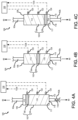
- ram 106 will be located closer to second end 110 during non-braking conditions.
- FIG. 4A shows piston with the brake stack 62 ( FIG. 2 ) in an unworn state during a non-braking condition.
- FIG. 4B shows piston 102 with brake stack 62 in 50% worn state during a non-braking condition.
- FIG. 4C shows piston 102 with brake stack 62 in 90% worn state during a non-braking condition.
- ram 106 is located closer to first end 108 of cylinder 104, during non-braking conditions, as compared to the position of ram 106 in the 50% worn state ( FIG. 4B ) during non-braking conditions.
- the 50% unworn state FIG. 4B
- ram 106 is located closer to first end 108 of cylinder 104, during non-braking conditions, as compared to the position of ram 106 in the 90% worn state ( FIG. 4C ) during non-braking conditions.
- system 100 includes one or more sensors, such as sensor 120, sensor 122, and sensor 124, operationally coupled to piston 102.
- Sensors 120, 122, 124 are configured to detect the presence of ram 106 within the sensor's field of view.
- sensors 120, 122, 124 are attached to cylinder 104.
- Sensors 120, 122, 124 may comprise capacitive sensors, optical sensors, electromechanical sensors, pneumatic sensors, magnetic sensors, inductive sensors, or any other sensor capable of detecting the presence of ram 106.
- Sensors 120, 122, 124 may be configured to output a detection signal in response to detecting ram 106.
- Sensors 120, 122, 124 may output the detection signals to a display 130.
- Sensors 120, 122, 124 are electrically coupled to and are in operable communication with display 130.
- Sensors 120, 122, 124 may be coupled to display 130 via wired or wireless connection.
- Display 130 may be configured to communicate information relating to brake stack 62 to the aircraft operator, maintenance crew, pilot, co-pilot, etc.
- display 130 may indicate a wear state of brake stack 62 and/or that maintenance or replacement of the brake stack 62 is needed.
- Display 130 may include lights, a screen, a speaker, a network access device that sends a message to a remote terminal, and/or the like.
- ram 106 is in the field of view of sensor 120, and sensor 120 outputs detection signal 132a to display 130.
- display 130 outputs a message (e.g., a illuminates a light, modifies a message on a screen, etc.) that indicated brake stack is in an unworn state.
- Positioning sensor 120 to correspond to an unworn brake stack may also allow for detection braking system anomalies. For example, ram 106 not being in the field of view of sensor 120, when multi-disk brake assembly 50 includes a new, unworn brake stack 62, indicates a fluid leak may be present in fluid supply line 92.
- ram 106 is in the field of view of sensor 122, and sensor 122 outputs detection signal 132b to display 130.
- display 130 outputs a message (e.g., a illuminates a light, modifies a message on a screen, etc.) that indicates brake stack is in a 50% worn state.
- ram 106 is in the field of view of sensor 124, and sensor 124 outputs detection signal 132c to display 130.
- display 130 outputs a message (e.g., a illuminates a light, modifies a message on a screen, etc.) that indicates brake stack is in a 90% worn state.
- system 100 is illustrated as having three (3) sensors, with sensor locations corresponding to the unworn state, the 50% worn state, and the 90% worn state, it is contemplated and understood that system 100 may include any number of sensors at any desired location along.
- system 100 may send signals corresponding to the wear state of the brake stack to friction disks suppliers. Sending signals directly to suppliers may allow the supplier to better determine the amount of friction disks will need to be manufactured in the coming months.
- Piston 102 may also serve as a cut-off valve to brake actuator 80. For example, if the pressure generated by fluid 116 drops significantly due to, for example, a burst or a leak in second portion 92b of fluid supply line 92, ram 106 translates to second end 110 of cylinder 104. Ram 106 may contact a floor 117 of cylinder 104 and/or block second orifice 118.
- ram 106 may be configured to block the flow of fluid 112 to second portion 92b of fluid supply line 92 and thus to brake actuator 80, in response to a fluid leak downstream of piston 102 (i.e., in response to a loss of fluid from second portion 92b of fluid supply line 92 and/or in response to the pressure within second portion 92b dropping below a threshold pressure).
- Ram 106 is thus configured to prevent fluid 112 from flowing to the burst fluid supply line.
- Employing piston 102 as a fluid cut-off may allow for the removal of one or more brake systems fuses, which are also configured to cut-off the supply of fluid in the event of a burst line.
- downstream refers to the flow direction from piston 102 to brake actuator 80 and from fluid reservoir 90 to piston 102, and is opposite of the "upstream” direction, which, as used herein, refers to the flow direction from brake actuator 80 to piston 102 and from piston 102 to fluid reservoir 90.
- multi-disk brake assembly 50 in FIG. 2 , may include system 200 in place of system 100.
- System 200 includes a piston 202.
- Piston 202 is fluidly coupled in line with fluid supply line 92.
- Piston 202 include a cylinder 204 and a ram 206 configured to translate within cylinder 204.
- First portion 92a of fluid supply line 92 fluidly couples cylinder 204 of piston 202 to fluid reservoir 90.
- first portion 92a may be coupled to a first end 208 of cylinder 204.
- a second portion 92b of fluid supply line 92 fluidly couples cylinder 204 of piston 202 to brake actuator 80.
- second portion 92b may be coupled to a second end 210 of cylinder 204.
- fluid 112 from fluid reservoir 90 flows into cylinder 204 via a first orifice 214 in cylinder 204, thereby increasing the volume of fluid 112 in cylinder 204.
- the increased volume of fluid 112 increases the pressure on ram 206, thereby causing ram 206 to translate toward second end 210 of cylinder 204.
- the translation of ram 206 towards second end 210 forces a fluid 116 located between ram 206 and second end 210 to flow out a second orifice 218 in cylinder 204 and into brake actuator 80.
- the fluid 116 from piston 202 forces brake ram 96 ( FIG. 2 ) to translate toward brake stack 62, thereby generating braking force.
- fluid 116 flows from brake actuator 80 into cylinder 204, ram 206 translates toward first end 208 of cylinder 204, and fluid 112 flows from cylinder 204 into fluid reservoir 90.
- fluid 116 flows from brake actuator 80 into cylinder 204, ram 206 translates toward first end 208 of cylinder 204, and fluid 112 flows from cylinder 204 into fluid reservoir 90.
- ram 206 will be located closer to second end 210 during non-braking conditions.
- system 200 includes a position sensor 220.
- Position sensor 220 is coupled to ram 206.
- Position sensor is configured to determine a position of ram 206.
- sensor 220 may comprise a linear variable differential transformer (LVDT).
- Sensor 220 may be electrically coupled to a display 230.
- Sensor 220 may output signals 232 corresponding to the position of ram 206 to display 230.
- Sensor 220 may be coupled to display 230 via a wired or a wireless connection.
- LVDT linear variable differential transformer
- Display 230 may be configured to communicate information relating to brake stack 62 to an operator, maintenance crew, pilot, co-pilot, etc.
- display 230 may indicate a wear state of brake stack 62 and/or that maintenance or replacement of the brake stack 62 is needed based on signals 232 from sensor 220.
- Display 230 may include lights, a screen, a speaker, a network access device that sends a message to a remote terminal, and/or the like.
- Sensor 220 may also allow other brake systems anomalies to be detected. For example, the axial thickness of the brake stack 62 not coinciding with the location of ram 206, indicates a fluid leak or brake system fault condition may be present.
- sensor 220 may allow for detection of the rate or speed at which ram 206 is translating within cylinder 204.
- the position of ram 206 changing at a greater rate than would be associated with the rate of normal brake stack may indicate the presence of a fault condition in fluid supply line 92 and/or in multi-disk brake assembly 50.
- system 200 may send signals corresponding to a wear state of the brake stack to friction disks suppliers. Sending signals directly to suppliers may allow the supplier to better determine the amount of friction disks that will need to be manufactured in the coming months.
- Piston 202 may also serve as a cut-off valve to brake actuator 80.
- ram 206 translates to second end 210 of cylinder 204 and blocks second orifice 218, thereby preventing the flow of fluid 112 to brake actuator 80.
- ram 206 prevents fluid 112 from flowing to the burst fluid line.
- Employing piston 202 as a fluid cut-off may allow for the removal of one or more brake systems fuses, which are also configured to cut-off the supply of fluid in the event of a burst line.
- Method 300 may comprise fluidly coupling a fluid supply line to a brake actuator (step 302).
- the brake actuator may include a brake ram configured to translate relative to a brake stack of a multi-disk brake assembly.
- Method 300 further includes coupling a piston between a first portion of the fluid supply line and a second portion of the fluid supply line (step 304) and operably coupling a first sensor to the piston (step 306).
- the piston includes a cylinder and a ram configured to translate within the cylinder.
- the first sensor is configured to detect a position of the ram.
- step 306 may include mounting the first sensor to a first location on the cylinder. In various embodiments, step 306 may include mounting the first sensor to the ram. In various embodiments, method 300 may further comprise mounting a second sensor to a second location on the cylinder. In various embodiments, the first location may be selected such that the ram will be located in the field of view of the first sensor when the brake stack is in an unworn state. In various embodiments, the second location is closer to the second portion of the fluid supply line, as compared to the first location. In various embodiments, method 300 may further comprise configuring the ram to cut-off a flow of fluid to the second portion of the fluid supply line in response to a loss of fluid in the second portion of the fluid supply line.
- references to "various embodiments”, “one embodiment”, “an embodiment”, “an example embodiment”, etc. indicate that the embodiment described may include a particular feature, structure, or characteristic, but every embodiment may not necessarily include the particular feature, structure, or characteristic. Moreover, such phrases are not necessarily referring to the same embodiment. Further, when a particular feature, structure, or characteristic is described in connection with an embodiment, it is submitted that it is within the knowledge of one skilled in the art to affect such feature, structure, or characteristic in connection with other embodiments whether or not explicitly described. After reading the description, it will be apparent to one skilled in the relevant art(s) how to implement the invention in alternative embodiments.
- the terms “comprises”, “comprising”, or any other variation thereof, are intended to cover a non-exclusive inclusion, such that a process, method, article, or apparatus that comprises a list of elements does not include only those elements but may include other elements not expressly listed or inherent to such process, method, article, or apparatus.
Landscapes
- Engineering & Computer Science (AREA)
- General Engineering & Computer Science (AREA)
- Mechanical Engineering (AREA)
- Transportation (AREA)
- Power Engineering (AREA)
- Physics & Mathematics (AREA)
- General Physics & Mathematics (AREA)
- Braking Arrangements (AREA)
Claims (13)
- System zum Bestimmen von Bremsverschleiß basierend auf dem Fluidvolumen, umfassend:einen Bremsaktuator (80), der einen Bremsstößel (96) beinhaltet, der so konfiguriert ist, dass er sich als Reaktion auf Änderungen des Fluiddrucks im Bremsaktuator verschiebt;eine Fluidversorgungsleitung (92), die mit dem Bremsaktuator fluidisch gekoppelt ist; gekennzeichnet durcheinen Kolben (102), der zwischen einem ersten Abschnitt der Fluidversorgungsleitung und einem zweiten Abschnitt der Fluidversorgungsleitung fluidgekoppelt ist, wobei der Kolben einen Zylinder (104) und einen Stößel (106) umfasst, der so konfiguriert ist, dass er sich innerhalb des Zylinders verschiebt; undeinen ersten Sensor (120), der mit dem Kolben wirkgekoppelt ist.
- System nach Anspruch 1, wobei der erste Sensor (120) so konfiguriert ist, dass er als Reaktion darauf, dass sich der Stößel im Sichtfeld des ersten Sensors befindet, ein Erkennungssignal ausgibt, und wobei der erste Sensor (120) vorzugsweise mit dem Zylinder gekoppelt ist.
- System nach Anspruch 2, ferner umfassend einen zweiten Sensor (122), der mit dem Zylinder gekoppelt ist, wobei der zweite Sensor im Vergleich zum ersten Sensor näher an dem zweiten Abschnitt der Fluidversorgungsleitung angeordnet ist, und vorzugsweise ferner eine Anzeige (130) umfasst, die elektrisch mit dem ersten Sensor und dem zweiten Sensor gekoppelt ist.
- System nach Anspruch 1, wobei der erste Sensor (120) mit dem Stößel gekoppelt ist und wobei der erste Sensor einen linearen variablen Differentialtransformator umfasst.
- System nach Anspruch 1, wobei der Stößel so konfiguriert ist, dass er einen Boden des Zylinders berührt und als Reaktion auf einen Fluidverlust aus dem zweiten Abschnitt der Fluidversorgungsleitung einen Fluidfluss zum zweiten Abschnitt der Fluidversorgungsleitung blockiert.
- System nach Anspruch 1, ferner umfassend:eine Vielzahl von Reibscheiben;wobei der Bremsaktuator (80) so konfiguriert ist, dass er sich relativ zu der Vielzahl von Reibscheiben verschiebt.
- Verfahren nach Anspruch 6, ferner umfassend:
einen Fluidbehälter (90), der mit dem ersten Abschnitt der Fluidversorgungsleitung fluidisch gekoppelt ist und vorzugsweise ferner umfasst:ein Bremsservoventil (94), das zwischen dem Kolben und dem Fluidbehälter gekoppelt ist; undein Wechselventil (140), das zwischen dem Kolben und dem Bremsaktuator gekoppelt ist. - System nach Anspruch 7, ferner umfassend eine Anzeige (130), die elektrisch mit dem ersten Sensor gekoppelt ist.
- System nach Anspruch 8, wobei der erste Sensor (120) mit dem Stößel gekoppelt ist.
- Verfahren zur Herstellung eines Systems zum Bestimmen von Bremsverschleiß basierend auf dem Fluidvolumen, wobei das Verfahren umfasst:fluidisches Koppeln einer Fluidversorgungsleitung mit einem Bremsaktuator, der so konfiguriert ist, dass er sich relativ zu einem Bremsstapel verschiebt;Koppeln eines Kolbens zwischen einem ersten Abschnitt der Fluidversorgungsleitung und einem zweiten Abschnitt der Fluidversorgungsleitung, wobei der Kolben einen Zylinder und einen Stößel umfasst, der so konfiguriert ist, dass er sich innerhalb des Zylinders verschiebt;Wirkkoppeln eines ersten Sensors mit dem Kolben, wobei der erste Sensor zum Erkennen einer Position des Stößels konfiguriert ist.
- Verfahren nach Anspruch 10, wobei Wirkkoppeln des ersten Sensors mit dem Kolben mindestens entweder Montieren des ersten Sensors an einer ersten Stelle am Zylinder oder Montieren des ersten Sensors am Stößel umfasst.
- Verfahren nach Anspruch 11, ferner umfassend Anbringen eines zweiten Sensors an einer zweiten Stelle am Zylinder, wobei die erste Stelle so ausgewählt wird, dass sich der Stößel im Sichtfeld des ersten Sensors befindet, wenn der Bremsstapel in unverschlissenem Zustand ist, und wobei die zweite Stelle im Vergleich zur ersten Stelle näher am zweiten Abschnitt der Fluidversorgungsleitung liegt.
- Verfahren nach Anspruch 10, ferner umfassend Konfigurieren des Stößels zum Unterbrechen eines Fluidflusses zu dem zweiten Abschnitt der Fluidversorgungsleitung als Reaktion auf einen Fluidverlust in dem zweiten Abschnitt der Fluidversorgungsleitung.
Applications Claiming Priority (1)
| Application Number | Priority Date | Filing Date | Title |
|---|---|---|---|
| US16/924,912 US11396285B2 (en) | 2020-07-09 | 2020-07-09 | Systems and methods for measuring brake wear |
Publications (2)
| Publication Number | Publication Date |
|---|---|
| EP3936397A1 EP3936397A1 (de) | 2022-01-12 |
| EP3936397B1 true EP3936397B1 (de) | 2024-01-03 |
Family
ID=76708024
Family Applications (1)
| Application Number | Title | Priority Date | Filing Date |
|---|---|---|---|
| EP21182321.6A Active EP3936397B1 (de) | 2020-07-09 | 2021-06-29 | Systeme und verfahren zur messung des bremsverschleisses |
Country Status (2)
| Country | Link |
|---|---|
| US (1) | US11396285B2 (de) |
| EP (1) | EP3936397B1 (de) |
Families Citing this family (2)
| Publication number | Priority date | Publication date | Assignee | Title |
|---|---|---|---|---|
| DE102023100789B3 (de) * | 2023-01-13 | 2024-06-13 | Zollern Gmbh & Co. Kg | Bremse mit einer Einrichtung zur Ermittlung einer Verschleißgrenze |
| FR3167417A1 (fr) * | 2024-10-11 | 2026-04-17 | Safran Landing Systems | Procédé de contrôle de l’usure de pièces de friction d’un système de freinage hydraulique et système de freinage hydraulique associé |
Family Cites Families (13)
| Publication number | Priority date | Publication date | Assignee | Title |
|---|---|---|---|---|
| US3828894A (en) | 1972-12-27 | 1974-08-13 | Goodyear Tire & Rubber | Telescopic piston for added brake wear adjustment |
| DE4212279A1 (de) * | 1992-04-11 | 1993-10-14 | Hella Kg Hueck & Co | Vorrichtung zur Überwachung des Verschleißes von Bremsbelägen, insbesondere von Kraftfahrzeugbremsbelägen |
| US6360853B1 (en) * | 1996-10-18 | 2002-03-26 | The Boeing Company | Balanced brake assembly having coincident piston application |
| DE10313676A1 (de) * | 2003-03-26 | 2004-10-07 | Imi Norgren-Herion Fluidtronic Gmbh & Co. Kg | Positionsmeßvorrichtung für fluidische Zylinder-Kolben-Anordnungen |
| US20100276233A1 (en) | 2009-04-30 | 2010-11-04 | Goodrich Corporation | System to eliminate electric actuator contamination |
| US8634971B2 (en) | 2009-05-05 | 2014-01-21 | Goodrich Corporation | Brake wear control system |
| GB2528322B (en) * | 2014-07-18 | 2020-08-05 | Airbus Operations Ltd | Determining integrity of braking control system |
| GB2547705A (en) | 2016-02-29 | 2017-08-30 | Meggitt Aerospace Ltd | Ultrasonic brake wear sensors |
| US20190264765A1 (en) | 2016-07-29 | 2019-08-29 | Trw Automotive U.S. Llc | Magnetic brake pad wear sensor |
| IL249908B (en) | 2016-12-28 | 2021-12-01 | Israel Aerospace Ind Ltd | Aircraft pylon |
| US10882498B2 (en) | 2017-04-18 | 2021-01-05 | Goodrich Corporation | Electrical power connection in an emergency park brake system |
| GB2571359A (en) * | 2018-02-27 | 2019-08-28 | Airbus Operations Ltd | Brake monitoring |
| US10836474B2 (en) | 2018-07-03 | 2020-11-17 | The Boeing Company | Aircraft landing gear steering systems and methods with enhanced shimmy protection |
-
2020
- 2020-07-09 US US16/924,912 patent/US11396285B2/en active Active
-
2021
- 2021-06-29 EP EP21182321.6A patent/EP3936397B1/de active Active
Also Published As
| Publication number | Publication date |
|---|---|
| EP3936397A1 (de) | 2022-01-12 |
| US20220009466A1 (en) | 2022-01-13 |
| US11396285B2 (en) | 2022-07-26 |
Similar Documents
| Publication | Publication Date | Title |
|---|---|---|
| US10800387B1 (en) | Retractable electronic wear pin | |
| EP3760504B1 (de) | Selektives bremsen von kohlenstoffbremsen zur verbesserung der lebensdauer | |
| EP3936397B1 (de) | Systeme und verfahren zur messung des bremsverschleisses | |
| EP3859182A1 (de) | Systeme und verfahren zur messung der erweiterten verschleisslänge von flugzeugbremsen | |
| EP3659880B1 (de) | Verschleisssensor für federbasierte bremse | |
| EP4227175A1 (de) | Hybridbremssysteme und -verfahren | |
| US11639160B2 (en) | Electrical power connection in an emergency park brake system | |
| US11492103B2 (en) | Distributed brake control systems and methods for high efficiency antiskid performance | |
| EP3659879A1 (de) | Temperaturüberwachung zur detektion des bremsenversagens | |
| EP3909818B1 (de) | Erkennung von bremsversagen unter verwendung der radgeschwindigkeit beim einfahren des fahrwerks | |
| EP3392140B1 (de) | Notfeststellbremssystem | |
| EP3560779B1 (de) | Messung des kontakterhaltenden steuerventilstroms für einen hydraulischen aktuator | |
| EP4147923B1 (de) | Flugzeugbremssystem | |
| US20230286476A1 (en) | Monitoring of landing gear servo valve assembly | |
| EP0229403B1 (de) | Bremsmomentbegrenzer | |
| EP4242077B1 (de) | Überwachung einer flugzeugfahrwerkservoventilanordnung |
Legal Events
| Date | Code | Title | Description |
|---|---|---|---|
| PUAI | Public reference made under article 153(3) epc to a published international application that has entered the european phase |
Free format text: ORIGINAL CODE: 0009012 |
|
| STAA | Information on the status of an ep patent application or granted ep patent |
Free format text: STATUS: THE APPLICATION HAS BEEN PUBLISHED |
|
| AK | Designated contracting states |
Kind code of ref document: A1 Designated state(s): AL AT BE BG CH CY CZ DE DK EE ES FI FR GB GR HR HU IE IS IT LI LT LU LV MC MK MT NL NO PL PT RO RS SE SI SK SM TR |
|
| B565 | Issuance of search results under rule 164(2) epc |
Effective date: 20211022 |
|
| STAA | Information on the status of an ep patent application or granted ep patent |
Free format text: STATUS: REQUEST FOR EXAMINATION WAS MADE |
|
| 17P | Request for examination filed |
Effective date: 20220628 |
|
| RBV | Designated contracting states (corrected) |
Designated state(s): AL AT BE BG CH CY CZ DE DK EE ES FI FR GB GR HR HU IE IS IT LI LT LU LV MC MK MT NL NO PL PT RO RS SE SI SK SM TR |
|
| STAA | Information on the status of an ep patent application or granted ep patent |
Free format text: STATUS: EXAMINATION IS IN PROGRESS |
|
| 17Q | First examination report despatched |
Effective date: 20230112 |
|
| GRAP | Despatch of communication of intention to grant a patent |
Free format text: ORIGINAL CODE: EPIDOSNIGR1 |
|
| STAA | Information on the status of an ep patent application or granted ep patent |
Free format text: STATUS: GRANT OF PATENT IS INTENDED |
|
| INTG | Intention to grant announced |
Effective date: 20230804 |
|
| P01 | Opt-out of the competence of the unified patent court (upc) registered |
Effective date: 20230922 |
|
| GRAS | Grant fee paid |
Free format text: ORIGINAL CODE: EPIDOSNIGR3 |
|
| GRAA | (expected) grant |
Free format text: ORIGINAL CODE: 0009210 |
|
| STAA | Information on the status of an ep patent application or granted ep patent |
Free format text: STATUS: THE PATENT HAS BEEN GRANTED |
|
| AK | Designated contracting states |
Kind code of ref document: B1 Designated state(s): AL AT BE BG CH CY CZ DE DK EE ES FI FR GB GR HR HU IE IS IT LI LT LU LV MC MK MT NL NO PL PT RO RS SE SI SK SM TR |
|
| REG | Reference to a national code |
Ref country code: GB Ref legal event code: FG4D |
|
| REG | Reference to a national code |
Ref country code: DE Ref legal event code: R096 Ref document number: 602021008239 Country of ref document: DE |
|
| REG | Reference to a national code |
Ref country code: CH Ref legal event code: EP |
|
| REG | Reference to a national code |
Ref country code: IE Ref legal event code: FG4D |
|
| REG | Reference to a national code |
Ref country code: LT Ref legal event code: MG9D |
|
| PG25 | Lapsed in a contracting state [announced via postgrant information from national office to epo] |
Ref country code: ES Free format text: LAPSE BECAUSE OF FAILURE TO SUBMIT A TRANSLATION OF THE DESCRIPTION OR TO PAY THE FEE WITHIN THE PRESCRIBED TIME-LIMIT Effective date: 20240103 |
|
| PG25 | Lapsed in a contracting state [announced via postgrant information from national office to epo] |
Ref country code: ES Free format text: LAPSE BECAUSE OF FAILURE TO SUBMIT A TRANSLATION OF THE DESCRIPTION OR TO PAY THE FEE WITHIN THE PRESCRIBED TIME-LIMIT Effective date: 20240103 |
|
| REG | Reference to a national code |
Ref country code: NL Ref legal event code: MP Effective date: 20240103 |
|
| REG | Reference to a national code |
Ref country code: AT Ref legal event code: MK05 Ref document number: 1646508 Country of ref document: AT Kind code of ref document: T Effective date: 20240103 |
|
| PG25 | Lapsed in a contracting state [announced via postgrant information from national office to epo] |
Ref country code: NL Free format text: LAPSE BECAUSE OF FAILURE TO SUBMIT A TRANSLATION OF THE DESCRIPTION OR TO PAY THE FEE WITHIN THE PRESCRIBED TIME-LIMIT Effective date: 20240103 |
|
| PG25 | Lapsed in a contracting state [announced via postgrant information from national office to epo] |
Ref country code: NL Free format text: LAPSE BECAUSE OF FAILURE TO SUBMIT A TRANSLATION OF THE DESCRIPTION OR TO PAY THE FEE WITHIN THE PRESCRIBED TIME-LIMIT Effective date: 20240103 |
|
| PG25 | Lapsed in a contracting state [announced via postgrant information from national office to epo] |
Ref country code: IS Free format text: LAPSE BECAUSE OF FAILURE TO SUBMIT A TRANSLATION OF THE DESCRIPTION OR TO PAY THE FEE WITHIN THE PRESCRIBED TIME-LIMIT Effective date: 20240503 |
|
| PG25 | Lapsed in a contracting state [announced via postgrant information from national office to epo] |
Ref country code: LT Free format text: LAPSE BECAUSE OF FAILURE TO SUBMIT A TRANSLATION OF THE DESCRIPTION OR TO PAY THE FEE WITHIN THE PRESCRIBED TIME-LIMIT Effective date: 20240103 |
|
| PG25 | Lapsed in a contracting state [announced via postgrant information from national office to epo] |
Ref country code: GR Free format text: LAPSE BECAUSE OF FAILURE TO SUBMIT A TRANSLATION OF THE DESCRIPTION OR TO PAY THE FEE WITHIN THE PRESCRIBED TIME-LIMIT Effective date: 20240404 |
|
| PG25 | Lapsed in a contracting state [announced via postgrant information from national office to epo] |
Ref country code: RS Free format text: LAPSE BECAUSE OF FAILURE TO SUBMIT A TRANSLATION OF THE DESCRIPTION OR TO PAY THE FEE WITHIN THE PRESCRIBED TIME-LIMIT Effective date: 20240403 Ref country code: HR Free format text: LAPSE BECAUSE OF FAILURE TO SUBMIT A TRANSLATION OF THE DESCRIPTION OR TO PAY THE FEE WITHIN THE PRESCRIBED TIME-LIMIT Effective date: 20240103 |
|
| PG25 | Lapsed in a contracting state [announced via postgrant information from national office to epo] |
Ref country code: AT Free format text: LAPSE BECAUSE OF FAILURE TO SUBMIT A TRANSLATION OF THE DESCRIPTION OR TO PAY THE FEE WITHIN THE PRESCRIBED TIME-LIMIT Effective date: 20240103 Ref country code: CZ Free format text: LAPSE BECAUSE OF FAILURE TO SUBMIT A TRANSLATION OF THE DESCRIPTION OR TO PAY THE FEE WITHIN THE PRESCRIBED TIME-LIMIT Effective date: 20240103 |
|
| PG25 | Lapsed in a contracting state [announced via postgrant information from national office to epo] |
Ref country code: RS Free format text: LAPSE BECAUSE OF FAILURE TO SUBMIT A TRANSLATION OF THE DESCRIPTION OR TO PAY THE FEE WITHIN THE PRESCRIBED TIME-LIMIT Effective date: 20240403 Ref country code: NO Free format text: LAPSE BECAUSE OF FAILURE TO SUBMIT A TRANSLATION OF THE DESCRIPTION OR TO PAY THE FEE WITHIN THE PRESCRIBED TIME-LIMIT Effective date: 20240403 Ref country code: LT Free format text: LAPSE BECAUSE OF FAILURE TO SUBMIT A TRANSLATION OF THE DESCRIPTION OR TO PAY THE FEE WITHIN THE PRESCRIBED TIME-LIMIT Effective date: 20240103 Ref country code: IS Free format text: LAPSE BECAUSE OF FAILURE TO SUBMIT A TRANSLATION OF THE DESCRIPTION OR TO PAY THE FEE WITHIN THE PRESCRIBED TIME-LIMIT Effective date: 20240503 Ref country code: HR Free format text: LAPSE BECAUSE OF FAILURE TO SUBMIT A TRANSLATION OF THE DESCRIPTION OR TO PAY THE FEE WITHIN THE PRESCRIBED TIME-LIMIT Effective date: 20240103 Ref country code: GR Free format text: LAPSE BECAUSE OF FAILURE TO SUBMIT A TRANSLATION OF THE DESCRIPTION OR TO PAY THE FEE WITHIN THE PRESCRIBED TIME-LIMIT Effective date: 20240404 Ref country code: CZ Free format text: LAPSE BECAUSE OF FAILURE TO SUBMIT A TRANSLATION OF THE DESCRIPTION OR TO PAY THE FEE WITHIN THE PRESCRIBED TIME-LIMIT Effective date: 20240103 Ref country code: BG Free format text: LAPSE BECAUSE OF FAILURE TO SUBMIT A TRANSLATION OF THE DESCRIPTION OR TO PAY THE FEE WITHIN THE PRESCRIBED TIME-LIMIT Effective date: 20240103 Ref country code: AT Free format text: LAPSE BECAUSE OF FAILURE TO SUBMIT A TRANSLATION OF THE DESCRIPTION OR TO PAY THE FEE WITHIN THE PRESCRIBED TIME-LIMIT Effective date: 20240103 |
|
| PG25 | Lapsed in a contracting state [announced via postgrant information from national office to epo] |
Ref country code: PT Free format text: LAPSE BECAUSE OF FAILURE TO SUBMIT A TRANSLATION OF THE DESCRIPTION OR TO PAY THE FEE WITHIN THE PRESCRIBED TIME-LIMIT Effective date: 20240503 Ref country code: PL Free format text: LAPSE BECAUSE OF FAILURE TO SUBMIT A TRANSLATION OF THE DESCRIPTION OR TO PAY THE FEE WITHIN THE PRESCRIBED TIME-LIMIT Effective date: 20240103 |
|
| PG25 | Lapsed in a contracting state [announced via postgrant information from national office to epo] |
Ref country code: SE Free format text: LAPSE BECAUSE OF FAILURE TO SUBMIT A TRANSLATION OF THE DESCRIPTION OR TO PAY THE FEE WITHIN THE PRESCRIBED TIME-LIMIT Effective date: 20240103 Ref country code: PT Free format text: LAPSE BECAUSE OF FAILURE TO SUBMIT A TRANSLATION OF THE DESCRIPTION OR TO PAY THE FEE WITHIN THE PRESCRIBED TIME-LIMIT Effective date: 20240503 Ref country code: PL Free format text: LAPSE BECAUSE OF FAILURE TO SUBMIT A TRANSLATION OF THE DESCRIPTION OR TO PAY THE FEE WITHIN THE PRESCRIBED TIME-LIMIT Effective date: 20240103 Ref country code: LV Free format text: LAPSE BECAUSE OF FAILURE TO SUBMIT A TRANSLATION OF THE DESCRIPTION OR TO PAY THE FEE WITHIN THE PRESCRIBED TIME-LIMIT Effective date: 20240103 |
|
| REG | Reference to a national code |
Ref country code: DE Ref legal event code: R097 Ref document number: 602021008239 Country of ref document: DE |
|
| PG25 | Lapsed in a contracting state [announced via postgrant information from national office to epo] |
Ref country code: DK Free format text: LAPSE BECAUSE OF FAILURE TO SUBMIT A TRANSLATION OF THE DESCRIPTION OR TO PAY THE FEE WITHIN THE PRESCRIBED TIME-LIMIT Effective date: 20240103 |
|
| PG25 | Lapsed in a contracting state [announced via postgrant information from national office to epo] |
Ref country code: SM Free format text: LAPSE BECAUSE OF FAILURE TO SUBMIT A TRANSLATION OF THE DESCRIPTION OR TO PAY THE FEE WITHIN THE PRESCRIBED TIME-LIMIT Effective date: 20240103 |
|
| PG25 | Lapsed in a contracting state [announced via postgrant information from national office to epo] |
Ref country code: EE Free format text: LAPSE BECAUSE OF FAILURE TO SUBMIT A TRANSLATION OF THE DESCRIPTION OR TO PAY THE FEE WITHIN THE PRESCRIBED TIME-LIMIT Effective date: 20240103 |
|
| PG25 | Lapsed in a contracting state [announced via postgrant information from national office to epo] |
Ref country code: SK Free format text: LAPSE BECAUSE OF FAILURE TO SUBMIT A TRANSLATION OF THE DESCRIPTION OR TO PAY THE FEE WITHIN THE PRESCRIBED TIME-LIMIT Effective date: 20240103 |
|
| PG25 | Lapsed in a contracting state [announced via postgrant information from national office to epo] |
Ref country code: SM Free format text: LAPSE BECAUSE OF FAILURE TO SUBMIT A TRANSLATION OF THE DESCRIPTION OR TO PAY THE FEE WITHIN THE PRESCRIBED TIME-LIMIT Effective date: 20240103 Ref country code: SK Free format text: LAPSE BECAUSE OF FAILURE TO SUBMIT A TRANSLATION OF THE DESCRIPTION OR TO PAY THE FEE WITHIN THE PRESCRIBED TIME-LIMIT Effective date: 20240103 Ref country code: RO Free format text: LAPSE BECAUSE OF FAILURE TO SUBMIT A TRANSLATION OF THE DESCRIPTION OR TO PAY THE FEE WITHIN THE PRESCRIBED TIME-LIMIT Effective date: 20240103 Ref country code: EE Free format text: LAPSE BECAUSE OF FAILURE TO SUBMIT A TRANSLATION OF THE DESCRIPTION OR TO PAY THE FEE WITHIN THE PRESCRIBED TIME-LIMIT Effective date: 20240103 Ref country code: DK Free format text: LAPSE BECAUSE OF FAILURE TO SUBMIT A TRANSLATION OF THE DESCRIPTION OR TO PAY THE FEE WITHIN THE PRESCRIBED TIME-LIMIT Effective date: 20240103 |
|
| PLBE | No opposition filed within time limit |
Free format text: ORIGINAL CODE: 0009261 |
|
| STAA | Information on the status of an ep patent application or granted ep patent |
Free format text: STATUS: NO OPPOSITION FILED WITHIN TIME LIMIT |
|
| PG25 | Lapsed in a contracting state [announced via postgrant information from national office to epo] |
Ref country code: IT Free format text: LAPSE BECAUSE OF FAILURE TO SUBMIT A TRANSLATION OF THE DESCRIPTION OR TO PAY THE FEE WITHIN THE PRESCRIBED TIME-LIMIT Effective date: 20240103 |
|
| 26N | No opposition filed |
Effective date: 20241007 |
|
| PG25 | Lapsed in a contracting state [announced via postgrant information from national office to epo] |
Ref country code: IT Free format text: LAPSE BECAUSE OF FAILURE TO SUBMIT A TRANSLATION OF THE DESCRIPTION OR TO PAY THE FEE WITHIN THE PRESCRIBED TIME-LIMIT Effective date: 20240103 |
|
| REG | Reference to a national code |
Ref country code: DE Ref legal event code: R119 Ref document number: 602021008239 Country of ref document: DE |
|
| PG25 | Lapsed in a contracting state [announced via postgrant information from national office to epo] |
Ref country code: MC Free format text: LAPSE BECAUSE OF FAILURE TO SUBMIT A TRANSLATION OF THE DESCRIPTION OR TO PAY THE FEE WITHIN THE PRESCRIBED TIME-LIMIT Effective date: 20240103 |
|
| REG | Reference to a national code |
Ref country code: CH Ref legal event code: PL |
|
| PG25 | Lapsed in a contracting state [announced via postgrant information from national office to epo] |
Ref country code: LU Free format text: LAPSE BECAUSE OF NON-PAYMENT OF DUE FEES Effective date: 20240629 |
|
| PG25 | Lapsed in a contracting state [announced via postgrant information from national office to epo] |
Ref country code: DE Free format text: LAPSE BECAUSE OF NON-PAYMENT OF DUE FEES Effective date: 20250101 |
|
| PG25 | Lapsed in a contracting state [announced via postgrant information from national office to epo] |
Ref country code: IE Free format text: LAPSE BECAUSE OF NON-PAYMENT OF DUE FEES Effective date: 20240629 |
|
| PG25 | Lapsed in a contracting state [announced via postgrant information from national office to epo] |
Ref country code: SI Free format text: LAPSE BECAUSE OF FAILURE TO SUBMIT A TRANSLATION OF THE DESCRIPTION OR TO PAY THE FEE WITHIN THE PRESCRIBED TIME-LIMIT Effective date: 20240103 Ref country code: BE Free format text: LAPSE BECAUSE OF NON-PAYMENT OF DUE FEES Effective date: 20240630 Ref country code: CH Free format text: LAPSE BECAUSE OF NON-PAYMENT OF DUE FEES Effective date: 20240630 |
|
| REG | Reference to a national code |
Ref country code: BE Ref legal event code: MM Effective date: 20240630 |
|
| PGFP | Annual fee paid to national office [announced via postgrant information from national office to epo] |
Ref country code: GB Payment date: 20250520 Year of fee payment: 5 |
|
| PGFP | Annual fee paid to national office [announced via postgrant information from national office to epo] |
Ref country code: FR Payment date: 20250520 Year of fee payment: 5 |
|
| PG25 | Lapsed in a contracting state [announced via postgrant information from national office to epo] |
Ref country code: FI Free format text: LAPSE BECAUSE OF FAILURE TO SUBMIT A TRANSLATION OF THE DESCRIPTION OR TO PAY THE FEE WITHIN THE PRESCRIBED TIME-LIMIT Effective date: 20240103 |
|
| PG25 | Lapsed in a contracting state [announced via postgrant information from national office to epo] |
Ref country code: CY Free format text: LAPSE BECAUSE OF FAILURE TO SUBMIT A TRANSLATION OF THE DESCRIPTION OR TO PAY THE FEE WITHIN THE PRESCRIBED TIME-LIMIT; INVALID AB INITIO Effective date: 20210629 |
|
| PG25 | Lapsed in a contracting state [announced via postgrant information from national office to epo] |
Ref country code: HU Free format text: LAPSE BECAUSE OF FAILURE TO SUBMIT A TRANSLATION OF THE DESCRIPTION OR TO PAY THE FEE WITHIN THE PRESCRIBED TIME-LIMIT; INVALID AB INITIO Effective date: 20210629 |