EP3943246B1 - Dispositif et procédé d'usinage de pièces en forme de plaque - Google Patents
Dispositif et procédé d'usinage de pièces en forme de plaque Download PDFInfo
- Publication number
- EP3943246B1 EP3943246B1 EP21178978.9A EP21178978A EP3943246B1 EP 3943246 B1 EP3943246 B1 EP 3943246B1 EP 21178978 A EP21178978 A EP 21178978A EP 3943246 B1 EP3943246 B1 EP 3943246B1
- Authority
- EP
- European Patent Office
- Prior art keywords
- machining tool
- suction
- cover layer
- suction device
- machining
- Prior art date
- Legal status (The legal status is an assumption and is not a legal conclusion. Google has not performed a legal analysis and makes no representation as to the accuracy of the status listed.)
- Active
Links
Images


Classifications
-
- B—PERFORMING OPERATIONS; TRANSPORTING
- B27—WORKING OR PRESERVING WOOD OR SIMILAR MATERIAL; NAILING OR STAPLING MACHINES IN GENERAL
- B27C—PLANING, DRILLING, MILLING, TURNING OR UNIVERSAL MACHINES FOR WOOD OR SIMILAR MATERIAL
- B27C5/00—Machines designed for producing special profiles or shaped work, e.g. by rotary cutters; Equipment therefor
-
- B—PERFORMING OPERATIONS; TRANSPORTING
- B25—HAND TOOLS; PORTABLE POWER-DRIVEN TOOLS; MANIPULATORS
- B25B—TOOLS OR BENCH DEVICES NOT OTHERWISE PROVIDED FOR, FOR FASTENING, CONNECTING, DISENGAGING, OR HOLDING
- B25B11/00—Work holders not covered by any preceding group in the subclass, e.g. magnetic work holders, vacuum work holders
- B25B11/005—Vacuum work holders
Definitions
- EP 3 278 923 A1 belongs to the state of the art and DE 10 2016 213841A1 describes a device according to the preamble of claim 1.
- the suction device ensures that it sucks in the top layer. This ensures that any vibrations of the top layer caused by the processing unit are dampened or avoided by their suction. In this way, the processing of the workpiece can be controlled much more precisely, since vibrations in the top layer can no longer cause the processing unit to possibly damage parts of the top layer.
- the suction device is preferably also only arranged in the region of the machining tool. This means that the suction device does not assume a suction clamping function or the like, but is only used more or less locally at the point on the upper side of the workpiece where the corresponding processing unit is located on the underside.
- the device according to the invention is designed in such a way that the suction device can be displaced as a function of the displacement of the processing tool. This displacement preferably runs in a direction parallel to the top layer of the workpiece. More preferably, a control device is provided for this purpose, which can be part of the device according to the invention and causes the displacement of the suction device depending on the movement of the processing tool or the underfloor processing unit.
- the main suction direction of the suction device runs parallel to the axis of rotation of the processing tool. Since the tool is moved in the direction of the top layer during the machining process during chip removal, the distance between the top layer held or sucked in by the suction device and the tip of the machining tool can be determined and controlled particularly easily.
- the suction device comprises a suction section and the device, in particular the suction device, further comprises at least one feeler shoe spaced apart from the suction section for resting on a surface of the workpiece to be machined. The feeler shoe then serves as a reference for controlling the position of the machining tool.
- the suction section does not have to lie directly on the surface of the workpiece, it can be provided that it has a support element or a plurality of support elements for supporting the suction section on a workpiece surface.
- the suction section itself can be designed as a support element.
- At least one, preferably a plurality, of the support elements can/can be designed to be exchangeable. For example, an adaptation to corresponding workpiece surfaces can take place.
- the suction can take place in such a way that a relative movement between the workpiece and the suction device is still possible. Provision can preferably be made for the cover layer to be pulled by the suction device in an area adjacent to the material to be removed by the machining tool being held. In this way, an oscillation or vibration of the cover layer is prevented precisely in those areas where the tool acts on the workpiece from the side of the cover layer facing away from the suction device.
- the machine control constantly determines the distance of the tool tip to the top layer, in particular to a feeler shoe lying on the top layer, so that the further feed of the tool in the direction of the top layer is controlled by the machine control depending on a defined minimum distance, which ideally corresponds exactly to the thickness of the top layer and can be stopped if necessary.
- a depth for the removal of material is specified as a target value, with the actual distance between the suction device acting on the cover layer and/or a feeler shoe resting on the cover layer on the one hand and the processing tool on the other hand being determined and the actual distance being compared with the target value will.
- Step b is preferred. terminated when the setpoint is reached.
- step b it can be provided that the processing tool is moved away from the cover layer. The workpiece can then be removed from the fixture.
- the processing tool is moved in a direction parallel to the top layer.
- the suction device is carried along with the movement of the processing tool in the same direction parallel to the top layer.
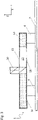
- FIG. 1 and 2 an exemplary workpiece 1 is shown, which with the device according to the invention or the process according to the invention can be produced.
- Z designates the vertical direction
- X and Y are the two spatial directions that run parallel to the workpiece surface or parallel to its cover layer 10 .
- the workpiece 1 itself is a panel-shaped workpiece, for example made of wood or wood substitutes, but can also be made of plastics or, for example, be a lightweight panel or honeycomb panel.
- a recess 12 is to be made in the workpiece, in which, in the example shown, a sink, for example, is to be mounted on the workpiece 1 from the underside of the workpiece.
- 14 designates the actual core layer or carrier layer of the plate
- 10 is a cover layer applied to the upper side, which can usually be a few tenths of a millimeter to a few millimeters thick.
- the cover layer 10 has a recess 11 below which a sink, not shown here, is to be attached.
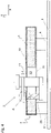
- the solution according to the invention is figure 4 pictured.
- the workpiece 1 lies on the supports 4 and the cover layer 10 lies on top in the example shown.
- the tool 20 is advanced from the underside in the direction Z of the cover layer 10, as a result of which the opening 13 and the recess 12 are formed.
- a recess 11 is contained in the cover layer 10 in this example. However, this does not have to be included.
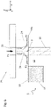
- the detail A is in various embodiments of the invention in the Figures 5 to 9 shown.
- FIG 5 one recognizes the processing tool 20 and a suction device 21, which acts on the cover layer 10 of the workpiece 1 and on the core layer or carrier layer 14 is attached.
- the suction device 21 preferably uses the Bernoulli effect by blowing air through a channel 22 in the direction of the arrow P1 into the area between the suction section 23 serving as the outer wall and the suction section 24 serving as the inner wall.
- the annular gap between the suction sections 23 and 24 tapers towards the underside (towards the object to be sucked--in this case towards the cover layer 10--) and exits again laterally above the cover layer (P2, P3).
- the cover layer is sucked in in the area 10a that protrudes over the core layer 14 here, so that a force F is exerted on the cover layer 10 or 10a away from the tool 20 by the resulting negative pressure.
- support elements 23a and 23b designed as spacers are provided on the underside of the suction section 23, which create a minimum gap between the suction section 23 and the cover layer 10, 10a, so that the air P2 blown into the suction device 21 via the channel 22 escapes parallel to the cover layer 10 can.
- the suction device 21 holds the top layer 10 during the machining process, so that vibration caused by the machining unit 20 is largely suppressed.
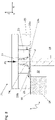
- the variant shown are provided on both sides and at a distance from the suction section 23 feeler shoes 25 .
- these feeler shoes 25 can also be a single circumferential feeler shoe, which partly or completely surrounds the suction section 23 .
- Such a feeler shoe 25 rests on the surface of the cover layer 10 and defines a zero line from which the machine control continuously detects and determines the distance between the tip of the tool 20 and this zero line. In this way, it can be ensured that the top layer 10 that is sucked in is not damaged by the tip of the tool 20 when the material is removed.
- Supporting elements 23a and 23b can also be provided in this variant, but do not have to be.
- the recess 12 is located between two sections of the carrier layer 14.
- the device according to the invention can also be used to process areas in which material is to be removed at the edge of a plate-shaped workpiece 1, so that at the end of the process a cover layer 10a protruding at the edge is formed.
- Such an example is in figure 8 shown.
- the remaining components shown correspond to those of the previous embodiments.
- the in figure 8 double feeler shoe or circumferential feeler shoe still shown is not absolutely necessary. Rather, it is sufficient, as in the embodiment of figure 9 is shown, a feeler shoe 25 for resting on the cover layer 10 is only provided on the side on which the carrier layer 14 is also present.
- the machining tool 20 or the underfloor machining unit having it can be moved parallel to the cover layer 10 by means of a control device in the directions X, Y.
- the control device of the device according to the invention is designed in such a way that the suction device is also carried along with the movement of the processing tool 20 or the underfloor processing unit that has it, so that the area on which the processing takes place on the underside of the workpiece 1 is always on the corresponding opposite Top of the cover layer 10 is also the suction device. This ensures that vibrations in the immediate vicinity of the machining tool 20 are dampened or avoided by the suction device 21 .
Landscapes
- Life Sciences & Earth Sciences (AREA)
- Engineering & Computer Science (AREA)
- Mechanical Engineering (AREA)
- Wood Science & Technology (AREA)
- Forests & Forestry (AREA)
- Milling, Drilling, And Turning Of Wood (AREA)
Claims (21)
- Dispositif (2) pour l'usinage des pièces en forme de plaque (1), en particulier des pièces formées en bois ou/et en matériaux de substitution du bois ou/et des matières plastiques ou en forme de panneau alvéolaire, comportant un outil d'usinage (20) commandé et conçu de manière à pouvoir être déplacé, en particulier un outil de perçage ou de fraisage,dans lequel le dispositif (2) comporte en outre un dispositif d'aspiration (21) situé en face de l'outil d'usinage (20),dans lequel le dispositif d'aspiration (21) peut être déplacé en fonction du déplacement de l'outil d'usinage (20),caractérisée en ceque le dispositif d'aspiration (21) est en outre conçu de manière à être entraîné avec le mouvement de l'outil d'usinage (21) dans la même direction (X, Y).
- Dispositif (2) selon la revendication 1,
caractérisée en ce
que l'outil d'usinage (20) fait partie d'une unité d'usinage en sous-sol, en particulier d'une unité de fraisage en sous-sol. - Dispositif (2) selon la revendication 1 ou 2,
caractérisée en ce
que le dispositif d'aspiration (21) n'est agencé que dans la zone de l'outil d'usinage (20). - Dispositif (2) selon la revendication 1,
caractérisée en ce
que le dispositif d'aspiration (21) est une pince aspirante à effet Bernoulli et/ou une pince aspirante à éjecteur à vide. - Dispositif (2) selon l'une quelconque des revendications précédentes,
caractérisée en ce
que le dispositif d'aspiration (21) est en face de la pointe de l'outil d'usinage (20). - Dispositif (2) selon l'une quelconque des revendications précédentes,
caractérisée en ce
que la direction principale de l'aspiration (Z) du dispositif d'aspiration (21) s'étend parallèlement à l'axe de rotation de l'outil d'usinage (20). - Dispositif (2) selon l'une quelconque des revendications précédentes,
caractérisée en ce
que l'outil d'usinage (20) peut être déplacé dans au moins une première direction spatiale (Z) en direction du dispositif d'aspiration (21) ou dans la direction opposée à celle-ci. - Dispositif (2) selon la revendication 7,
caractérisée en ce
que l'outil d'usinage (20) peut être déplacé dans au moins une, de préférence, deux autres direction(s) spatiale(s) (X, Y). - Dispositif (2) selon l'une quelconque des revendications précédentes,
caractérisée en ce
que le dispositif d'aspiration (21) comporte une section d'aspiration (23, 24) et que le dispositif (2), en particulier le dispositif d'aspiration (21), en outre comporte au moins un sabot de palpage (25) espacé de la section d'aspiration (23, 24) destiné à être posé sur une surface de la pièce (1) à usiner. - Dispositif (2) selon la revendication 9,
caractérisée en ce
qu'il comporte deux sabots de palpage (25), qui sont agencés des deux côtés et espacés de la section d'aspiration (23, 24). - Dispositif (2) selon la revendication 9,
caractérisée en ce
que le sabot de palpage (25) contourne la section d'aspiration au moins partiellement, de préférence, entièrement. - Dispositif (2) selon l'une quelconque des revendications précédentes,
caractérisée en ce
qu'il comporte un moyen de commande qui est adapté pour commander et / ou déplacer l'outil d'usinage (20) et/ou actionner et/ou déplacer le dispositif d'aspiration (21). - Dispositif (2) selon l'une quelconque des revendications précédentes,
caractérisée en ce
que la section d'aspiration (23) comporte un élément de support (24) ou une pluralité d'éléments de support (23a, 23b) pour appuyer la section d'aspiration (23) sur une surface de la pièce ou est lui-même conçu comme un élément de support (24). - Dispositif (2) selon la revendication 13,
caractérisée en ce
qu'au moins un, de préférence, une pluralité d'élément(s) de support (23a, 23b) est/sont conçu(s) de manière interchangeable. - Procédé d'usinage d'une pièce en forme de plaque (1), en particulier formée en bois ou / et en matériaux de substitution du bois ou / et des matières plastiques ou / et en forme de panneau alvéolaire, en utilisant un dispositif (2) d'usinage des pièces en forme de plaque (1), qui comporte un outil d'usinage (20) commandé et déplaçable, et comporte en outre un dispositif d'aspiration (21) situé en face de l'outil d'usinage (20), dans lequel le dispositif d'aspiration (21) peut être déplacé en fonction du déplacement de l'outil d'usinage (20), et dans lequel le procédé comporte le suivant :a. fournir une pièce en forme de plaque (1) avec une première face comportant une couche supérieure (10),b. usiner la pièce (1) avec l'outil d'usinage (20) en enlevant du matériau avec celui-ci depuis la deuxième face de la pièce (1) opposée à la première face, dans la direction (Z) de la première face,c. dans lequel, pendant l'opération d'usinage b. le dispositif d'aspiration (21) aspire la couche supérieure (10) sur sa face extérieure,caractérisée en ce
que l'outil d'usinage (20) est déplacé dans une direction (X, Y) parallèlement à la couche supérieure (10), dans lequel le dispositif d'aspiration (21) est entraîné avec le mouvement de l'outil d'usinage (21) dans la même direction (X, Y). - Procédé selon la revendication 15,
caractérisée en ce
que la couche supérieure (10) est maintenue par le dispositif d'aspiration (21) dans une zone adjacente au matériau à enlever par l'outil d'usinage (20). - Procédé selon la revendication 15 ou 16,
caractérisée en ce
que l'enlèvement de matériau est effectué par l'outil d'usinage (20) jusqu'à ce que la face intérieure de la couche supérieure (10) opposée à la face extérieure soit atteinte. - Procédé selon l'une quelconque des revendications 15 à 17,
caractérisée en ce
qu'une profondeur pour l'enlèvement du matériau est prédéfinie comme valeur de consigne, dans laquelle la distance réelle entre le dispositif d'aspiration (21) attaquant sur la couche supérieure (10) et/ou un sabot de palpage (25) reposant sur la couche supérieure (10) d'une part et l'outil d'usinage (20) d'autre part est déterminée et la distance réelle est comparée à la valeur de consigne. - Procédé selon la revendication 15,
caractérisée en ce
que l'étape b. est terminée lorsque la valeur de consigne est atteinte. - Procédé selon l'une quelconque des revendications 15 à 19,
caractérisée en ce
qu'un dispositif selon l'une quelconque des revendications 1 à 12 est utilisé et que dans l'étape b. les sous-étapes suivantes sont réalisées :b1) le dispositif (2) est approché de la pièce (1),b2) un palpage est réalisé sur la couche supérieure (10) par l'intermédiaire du dispositif d'aspiration (21),b3) l'outil d'usinage (20) est déplacé en direction de la couche supérieure (10) jusqu'à un endroit prédéfini,b4) le dispositif (2) est déplacé parallèlement à la couche supérieure (10) et enlève ainsi du matériau. - Procédé selon la revendication 20,
caractérisée en ce
qu'à la fin de l'étape b., l'outil d'usinage (2) est éloigné de la couche supérieure (10)
Applications Claiming Priority (1)
| Application Number | Priority Date | Filing Date | Title |
|---|---|---|---|
| DE102020119117.0A DE102020119117A1 (de) | 2020-07-21 | 2020-07-21 | Vorrichtung und Verfahren zum Bearbeiten plattenförmiger Werkstücke |
Publications (2)
| Publication Number | Publication Date |
|---|---|
| EP3943246A1 EP3943246A1 (fr) | 2022-01-26 |
| EP3943246B1 true EP3943246B1 (fr) | 2023-01-04 |
Family
ID=76764794
Family Applications (1)
| Application Number | Title | Priority Date | Filing Date |
|---|---|---|---|
| EP21178978.9A Active EP3943246B1 (fr) | 2020-07-21 | 2021-06-11 | Dispositif et procédé d'usinage de pièces en forme de plaque |
Country Status (5)
| Country | Link |
|---|---|
| EP (1) | EP3943246B1 (fr) |
| DE (1) | DE102020119117A1 (fr) |
| DK (1) | DK3943246T3 (fr) |
| FI (1) | FI3943246T3 (fr) |
| PL (1) | PL3943246T3 (fr) |
Cited By (1)
| Publication number | Priority date | Publication date | Assignee | Title |
|---|---|---|---|---|
| EP4726132A1 (fr) * | 2024-10-08 | 2026-04-15 | Brüninghoff Holz GmbH & Co. KG | Composant en bois comprenant un noyau céramique et son procédé de fabrication |
Citations (2)
| Publication number | Priority date | Publication date | Assignee | Title |
|---|---|---|---|---|
| EP0451479A2 (fr) * | 1990-04-12 | 1991-10-16 | Hans Heid Ag Holzbearbeitungs-Maschinen | Centre d'usinage pour pièces d'oeuvre en plaques pleines |
| DE102016213841A1 (de) * | 2016-07-27 | 2018-02-01 | Felder Kg | Spannvorrichtung |
Family Cites Families (6)
| Publication number | Priority date | Publication date | Assignee | Title |
|---|---|---|---|---|
| DE19718396C2 (de) | 1997-04-30 | 2001-10-31 | Homag Maschinenbau Ag | Erweiterungsaggregat für ein Bearbeitungszentrum |
| DE10026069C2 (de) | 2000-05-25 | 2003-01-09 | Homag Maschinenbau Ag | CNC-Bearbeitungszentrum sowie Verfahren zur Holzbearbeitung |
| DE10039970B4 (de) | 2000-08-16 | 2007-06-21 | Homag Maschinenbau Ag | Bearbeitungszentrum und Verfahren zum Bearbeiten von mehreren Werkstücken |
| DE20321663U1 (de) | 2003-12-10 | 2009-03-12 | Schwabedissen Maschinen Und Anlagen Service Gmbh | CNC-Bearbeitungsmaschine zum Aufteilen großformatiger Platten |
| DE102016114378A1 (de) * | 2016-08-03 | 2018-02-08 | J. Schmalz Gmbh | Handhabungsvorrichtung und Verfahren zur Überwachung einer Handhabungsvorrichtung |
| DE102019108575A1 (de) | 2018-04-03 | 2019-10-10 | Dirk Schweinforth | Verfahren zum Ausfräsen von plattenförmigen Werkstücken aus einer Materialplatte |
-
2020
- 2020-07-21 DE DE102020119117.0A patent/DE102020119117A1/de not_active Withdrawn
-
2021
- 2021-06-11 PL PL21178978.9T patent/PL3943246T3/pl unknown
- 2021-06-11 EP EP21178978.9A patent/EP3943246B1/fr active Active
- 2021-06-11 FI FIEP21178978.9T patent/FI3943246T3/fi active
- 2021-06-11 DK DK21178978.9T patent/DK3943246T3/da active
Patent Citations (2)
| Publication number | Priority date | Publication date | Assignee | Title |
|---|---|---|---|---|
| EP0451479A2 (fr) * | 1990-04-12 | 1991-10-16 | Hans Heid Ag Holzbearbeitungs-Maschinen | Centre d'usinage pour pièces d'oeuvre en plaques pleines |
| DE102016213841A1 (de) * | 2016-07-27 | 2018-02-01 | Felder Kg | Spannvorrichtung |
Cited By (1)
| Publication number | Priority date | Publication date | Assignee | Title |
|---|---|---|---|---|
| EP4726132A1 (fr) * | 2024-10-08 | 2026-04-15 | Brüninghoff Holz GmbH & Co. KG | Composant en bois comprenant un noyau céramique et son procédé de fabrication |
Also Published As
| Publication number | Publication date |
|---|---|
| DK3943246T3 (da) | 2023-02-06 |
| FI3943246T3 (fi) | 2023-01-31 |
| PL3943246T3 (pl) | 2023-04-17 |
| EP3943246A1 (fr) | 2022-01-26 |
| DE102020119117A1 (de) | 2022-01-27 |
Similar Documents
| Publication | Publication Date | Title |
|---|---|---|
| EP0418779B1 (fr) | Méthode pour manufacture de pièces d'oeuvre par découpage, en particulier dans un outil à contre découpage à précision | |
| DE3917612A1 (de) | Niederhalte- und spanentfernvorrichtung fuer eine schneidmaschine | |
| DE10300818B4 (de) | Stanzwerkzeug, insbesondere für Green Sheets | |
| EP2392438B1 (fr) | Dispositif de traitement | |
| DE69507964T2 (de) | Einrichtung zum greifen und fördern von blattmaterial sowie ein damit versehener manipulator | |
| EP2903790B1 (fr) | Méthode et unité de outil pour le justage de la fente entre les parties de l'outil | |
| EP3885085B1 (fr) | Outil de poinçonnage | |
| EP0473954A1 (fr) | Dispositif de serrage pour pièces d'usinage | |
| EP3943246B1 (fr) | Dispositif et procédé d'usinage de pièces en forme de plaque | |
| DE4216338C2 (de) | Schutzhaube für Holzfräsmaschinen | |
| EP1186366B1 (fr) | Outil et procédé pour l'usinage d'une pièce | |
| EP3175961B1 (fr) | Dispositif de compression pour une machine-outil servant à l'usinage de pièces en bois, en matière plastique et similaire et machine-outil comprenant au moins un dispositif de compression | |
| CH655041A5 (de) | Schneidpresse zur bearbeitung plattenfoermiger bauteile. | |
| EP0654333A1 (fr) | Machine à travailler des pièces à usiner en bois, plastique ou similaires | |
| EP0585576B1 (fr) | Machine à poinçonner | |
| EP2502716B1 (fr) | Outil pour une machine de traitement de tôle et procédé de séparation d'une feuille | |
| DE102018125085A1 (de) | Fixiervorrichtung, Bearbeitungskopf, Werkzeugmaschine und Verfahren zum Fixieren eines Werkstücks | |
| EP0411430A2 (fr) | Machine outil | |
| EP2184118A1 (fr) | Dévêtisseur étagé et procédé destiné à évacuer des pièces en tôle de machines de poinçonnage | |
| EP3124191B1 (fr) | Groupe d'usinage pour l'usinage de pieces usinees en forme de plaque et procede d'usinage d'une piece usinee en forme de plaque | |
| EP3849763B1 (fr) | Dispositif de coupe | |
| DE102005002595A1 (de) | Vorschubvorrichtung für plattenförmige Werkstücke, sowie Spannzange zur Verwendung bei einer solchen Vorschubvorrichtung | |
| DE20205479U1 (de) | Vorrichtung zum Erzeugen von Aussparungen in dünnwandigen Platten | |
| DE9012791U1 (de) | Vorrichtung zum Positionieren von Werkstücken bei der spanabhebenden Verformung | |
| WO2019029935A1 (fr) | Outil et procédé pour l'usinage de pièces en forme de plaque, notamment des tôles |
Legal Events
| Date | Code | Title | Description |
|---|---|---|---|
| PUAI | Public reference made under article 153(3) epc to a published international application that has entered the european phase |
Free format text: ORIGINAL CODE: 0009012 |
|
| STAA | Information on the status of an ep patent application or granted ep patent |
Free format text: STATUS: REQUEST FOR EXAMINATION WAS MADE |
|
| 17P | Request for examination filed |
Effective date: 20211210 |
|
| AK | Designated contracting states |
Kind code of ref document: A1 Designated state(s): AL AT BE BG CH CY CZ DE DK EE ES FI FR GB GR HR HU IE IS IT LI LT LU LV MC MK MT NL NO PL PT RO RS SE SI SK SM TR |
|
| STAA | Information on the status of an ep patent application or granted ep patent |
Free format text: STATUS: EXAMINATION IS IN PROGRESS |
|
| 17Q | First examination report despatched |
Effective date: 20220307 |
|
| GRAP | Despatch of communication of intention to grant a patent |
Free format text: ORIGINAL CODE: EPIDOSNIGR1 |
|
| STAA | Information on the status of an ep patent application or granted ep patent |
Free format text: STATUS: GRANT OF PATENT IS INTENDED |
|
| RBV | Designated contracting states (corrected) |
Designated state(s): AL AT BE BG CH CY CZ DE DK EE ES FI FR GB GR HR HU IE IS IT LI LT LU LV MC MK MT NL NO PL PT RO RS SE SI SK SM TR |
|
| INTG | Intention to grant announced |
Effective date: 20220809 |
|
| GRAS | Grant fee paid |
Free format text: ORIGINAL CODE: EPIDOSNIGR3 |
|
| GRAA | (expected) grant |
Free format text: ORIGINAL CODE: 0009210 |
|
| STAA | Information on the status of an ep patent application or granted ep patent |
Free format text: STATUS: THE PATENT HAS BEEN GRANTED |
|
| AK | Designated contracting states |
Kind code of ref document: B1 Designated state(s): AL AT BE BG CH CY CZ DE DK EE ES FI FR GB GR HR HU IE IS IT LI LT LU LV MC MK MT NL NO PL PT RO RS SE SI SK SM TR |
|
| REG | Reference to a national code |
Ref country code: GB Ref legal event code: FG4D Free format text: NOT ENGLISH |
|
| REG | Reference to a national code |
Ref country code: DE Ref legal event code: R096 Ref document number: 502021000361 Country of ref document: DE |
|
| REG | Reference to a national code |
Ref country code: CH Ref legal event code: EP |
|
| REG | Reference to a national code |
Ref country code: AT Ref legal event code: REF Ref document number: 1541594 Country of ref document: AT Kind code of ref document: T Effective date: 20230115 |
|
| REG | Reference to a national code |
Ref country code: FI Ref legal event code: FGE |
|
| REG | Reference to a national code |
Ref country code: IE Ref legal event code: FG4D Free format text: LANGUAGE OF EP DOCUMENT: GERMAN |
|
| REG | Reference to a national code |
Ref country code: DK Ref legal event code: T3 Effective date: 20230201 |
|
| REG | Reference to a national code |
Ref country code: NO Ref legal event code: T2 Effective date: 20230104 |
|
| REG | Reference to a national code |
Ref country code: SE Ref legal event code: TRGR |
|
| REG | Reference to a national code |
Ref country code: LT Ref legal event code: MG9D |
|
| REG | Reference to a national code |
Ref country code: NL Ref legal event code: MP Effective date: 20230104 |
|
| P01 | Opt-out of the competence of the unified patent court (upc) registered |
Effective date: 20230517 |
|
| PG25 | Lapsed in a contracting state [announced via postgrant information from national office to epo] |
Ref country code: NL Free format text: LAPSE BECAUSE OF FAILURE TO SUBMIT A TRANSLATION OF THE DESCRIPTION OR TO PAY THE FEE WITHIN THE PRESCRIBED TIME-LIMIT Effective date: 20230104 |
|
| PG25 | Lapsed in a contracting state [announced via postgrant information from national office to epo] |
Ref country code: RS Free format text: LAPSE BECAUSE OF FAILURE TO SUBMIT A TRANSLATION OF THE DESCRIPTION OR TO PAY THE FEE WITHIN THE PRESCRIBED TIME-LIMIT Effective date: 20230104 Ref country code: PT Free format text: LAPSE BECAUSE OF FAILURE TO SUBMIT A TRANSLATION OF THE DESCRIPTION OR TO PAY THE FEE WITHIN THE PRESCRIBED TIME-LIMIT Effective date: 20230504 Ref country code: LV Free format text: LAPSE BECAUSE OF FAILURE TO SUBMIT A TRANSLATION OF THE DESCRIPTION OR TO PAY THE FEE WITHIN THE PRESCRIBED TIME-LIMIT Effective date: 20230104 Ref country code: LT Free format text: LAPSE BECAUSE OF FAILURE TO SUBMIT A TRANSLATION OF THE DESCRIPTION OR TO PAY THE FEE WITHIN THE PRESCRIBED TIME-LIMIT Effective date: 20230104 Ref country code: HR Free format text: LAPSE BECAUSE OF FAILURE TO SUBMIT A TRANSLATION OF THE DESCRIPTION OR TO PAY THE FEE WITHIN THE PRESCRIBED TIME-LIMIT Effective date: 20230104 Ref country code: ES Free format text: LAPSE BECAUSE OF FAILURE TO SUBMIT A TRANSLATION OF THE DESCRIPTION OR TO PAY THE FEE WITHIN THE PRESCRIBED TIME-LIMIT Effective date: 20230104 |
|
| PG25 | Lapsed in a contracting state [announced via postgrant information from national office to epo] |
Ref country code: IS Free format text: LAPSE BECAUSE OF FAILURE TO SUBMIT A TRANSLATION OF THE DESCRIPTION OR TO PAY THE FEE WITHIN THE PRESCRIBED TIME-LIMIT Effective date: 20230504 Ref country code: GR Free format text: LAPSE BECAUSE OF FAILURE TO SUBMIT A TRANSLATION OF THE DESCRIPTION OR TO PAY THE FEE WITHIN THE PRESCRIBED TIME-LIMIT Effective date: 20230405 |
|
| REG | Reference to a national code |
Ref country code: DE Ref legal event code: R097 Ref document number: 502021000361 Country of ref document: DE |
|
| PG25 | Lapsed in a contracting state [announced via postgrant information from national office to epo] |
Ref country code: SM Free format text: LAPSE BECAUSE OF FAILURE TO SUBMIT A TRANSLATION OF THE DESCRIPTION OR TO PAY THE FEE WITHIN THE PRESCRIBED TIME-LIMIT Effective date: 20230104 Ref country code: RO Free format text: LAPSE BECAUSE OF FAILURE TO SUBMIT A TRANSLATION OF THE DESCRIPTION OR TO PAY THE FEE WITHIN THE PRESCRIBED TIME-LIMIT Effective date: 20230104 Ref country code: EE Free format text: LAPSE BECAUSE OF FAILURE TO SUBMIT A TRANSLATION OF THE DESCRIPTION OR TO PAY THE FEE WITHIN THE PRESCRIBED TIME-LIMIT Effective date: 20230104 Ref country code: CZ Free format text: LAPSE BECAUSE OF FAILURE TO SUBMIT A TRANSLATION OF THE DESCRIPTION OR TO PAY THE FEE WITHIN THE PRESCRIBED TIME-LIMIT Effective date: 20230104 |
|
| PLBE | No opposition filed within time limit |
Free format text: ORIGINAL CODE: 0009261 |
|
| STAA | Information on the status of an ep patent application or granted ep patent |
Free format text: STATUS: NO OPPOSITION FILED WITHIN TIME LIMIT |
|
| PG25 | Lapsed in a contracting state [announced via postgrant information from national office to epo] |
Ref country code: SK Free format text: LAPSE BECAUSE OF FAILURE TO SUBMIT A TRANSLATION OF THE DESCRIPTION OR TO PAY THE FEE WITHIN THE PRESCRIBED TIME-LIMIT Effective date: 20230104 |
|
| 26N | No opposition filed |
Effective date: 20231005 |
|
| PG25 | Lapsed in a contracting state [announced via postgrant information from national office to epo] |
Ref country code: MC Free format text: LAPSE BECAUSE OF FAILURE TO SUBMIT A TRANSLATION OF THE DESCRIPTION OR TO PAY THE FEE WITHIN THE PRESCRIBED TIME-LIMIT Effective date: 20230104 |
|
| PG25 | Lapsed in a contracting state [announced via postgrant information from national office to epo] |
Ref country code: SI Free format text: LAPSE BECAUSE OF FAILURE TO SUBMIT A TRANSLATION OF THE DESCRIPTION OR TO PAY THE FEE WITHIN THE PRESCRIBED TIME-LIMIT Effective date: 20230104 Ref country code: MC Free format text: LAPSE BECAUSE OF FAILURE TO SUBMIT A TRANSLATION OF THE DESCRIPTION OR TO PAY THE FEE WITHIN THE PRESCRIBED TIME-LIMIT Effective date: 20230104 |
|
| REG | Reference to a national code |
Ref country code: BE Ref legal event code: MM Effective date: 20230630 |
|
| PG25 | Lapsed in a contracting state [announced via postgrant information from national office to epo] |
Ref country code: LU Free format text: LAPSE BECAUSE OF NON-PAYMENT OF DUE FEES Effective date: 20230611 |
|
| REG | Reference to a national code |
Ref country code: IE Ref legal event code: MM4A |
|
| PG25 | Lapsed in a contracting state [announced via postgrant information from national office to epo] |
Ref country code: LU Free format text: LAPSE BECAUSE OF NON-PAYMENT OF DUE FEES Effective date: 20230611 |
|
| PG25 | Lapsed in a contracting state [announced via postgrant information from national office to epo] |
Ref country code: IE Free format text: LAPSE BECAUSE OF NON-PAYMENT OF DUE FEES Effective date: 20230611 |
|
| PG25 | Lapsed in a contracting state [announced via postgrant information from national office to epo] |
Ref country code: IE Free format text: LAPSE BECAUSE OF NON-PAYMENT OF DUE FEES Effective date: 20230611 |
|
| PG25 | Lapsed in a contracting state [announced via postgrant information from national office to epo] |
Ref country code: BE Free format text: LAPSE BECAUSE OF NON-PAYMENT OF DUE FEES Effective date: 20230630 |
|
| PG25 | Lapsed in a contracting state [announced via postgrant information from national office to epo] |
Ref country code: BG Free format text: LAPSE BECAUSE OF FAILURE TO SUBMIT A TRANSLATION OF THE DESCRIPTION OR TO PAY THE FEE WITHIN THE PRESCRIBED TIME-LIMIT Effective date: 20230104 |
|
| PG25 | Lapsed in a contracting state [announced via postgrant information from national office to epo] |
Ref country code: BG Free format text: LAPSE BECAUSE OF FAILURE TO SUBMIT A TRANSLATION OF THE DESCRIPTION OR TO PAY THE FEE WITHIN THE PRESCRIBED TIME-LIMIT Effective date: 20230104 |
|
| PGFP | Annual fee paid to national office [announced via postgrant information from national office to epo] |
Ref country code: FI Payment date: 20250618 Year of fee payment: 5 |
|
| PGFP | Annual fee paid to national office [announced via postgrant information from national office to epo] |
Ref country code: PL Payment date: 20250527 Year of fee payment: 5 |
|
| PGFP | Annual fee paid to national office [announced via postgrant information from national office to epo] |
Ref country code: DK Payment date: 20250618 Year of fee payment: 5 |
|
| PGFP | Annual fee paid to national office [announced via postgrant information from national office to epo] |
Ref country code: NO Payment date: 20250624 Year of fee payment: 5 |
|
| PGFP | Annual fee paid to national office [announced via postgrant information from national office to epo] |
Ref country code: FR Payment date: 20250623 Year of fee payment: 5 |
|
| PGFP | Annual fee paid to national office [announced via postgrant information from national office to epo] |
Ref country code: AT Payment date: 20250721 Year of fee payment: 5 |
|
| PG25 | Lapsed in a contracting state [announced via postgrant information from national office to epo] |
Ref country code: CY Free format text: LAPSE BECAUSE OF FAILURE TO SUBMIT A TRANSLATION OF THE DESCRIPTION OR TO PAY THE FEE WITHIN THE PRESCRIBED TIME-LIMIT; INVALID AB INITIO Effective date: 20210611 |
|
| PGFP | Annual fee paid to national office [announced via postgrant information from national office to epo] |
Ref country code: SE Payment date: 20250626 Year of fee payment: 5 |
|
| PG25 | Lapsed in a contracting state [announced via postgrant information from national office to epo] |
Ref country code: HU Free format text: LAPSE BECAUSE OF FAILURE TO SUBMIT A TRANSLATION OF THE DESCRIPTION OR TO PAY THE FEE WITHIN THE PRESCRIBED TIME-LIMIT; INVALID AB INITIO Effective date: 20210611 |
|
| PGFP | Annual fee paid to national office [announced via postgrant information from national office to epo] |
Ref country code: DE Payment date: 20250811 Year of fee payment: 5 |
|
| PGFP | Annual fee paid to national office [announced via postgrant information from national office to epo] |
Ref country code: IT Payment date: 20250620 Year of fee payment: 5 |
|
| PGFP | Annual fee paid to national office [announced via postgrant information from national office to epo] |
Ref country code: CH Payment date: 20250701 Year of fee payment: 5 |
|
| PG25 | Lapsed in a contracting state [announced via postgrant information from national office to epo] |
Ref country code: TR Free format text: LAPSE BECAUSE OF FAILURE TO SUBMIT A TRANSLATION OF THE DESCRIPTION OR TO PAY THE FEE WITHIN THE PRESCRIBED TIME-LIMIT Effective date: 20230104 |
|
| GBPC | Gb: european patent ceased through non-payment of renewal fee |
Effective date: 20250611 |
|
| PG25 | Lapsed in a contracting state [announced via postgrant information from national office to epo] |
Ref country code: GB Free format text: LAPSE BECAUSE OF NON-PAYMENT OF DUE FEES Effective date: 20250611 |