EP3945005A1 - Schutzvorrichtung für landfahrzeug - Google Patents
Schutzvorrichtung für landfahrzeug Download PDFInfo
- Publication number
- EP3945005A1 EP3945005A1 EP21187994.5A EP21187994A EP3945005A1 EP 3945005 A1 EP3945005 A1 EP 3945005A1 EP 21187994 A EP21187994 A EP 21187994A EP 3945005 A1 EP3945005 A1 EP 3945005A1
- Authority
- EP
- European Patent Office
- Prior art keywords
- vehicle
- strip
- flap
- flexible material
- reel
- Prior art date
- Legal status (The legal status is an assumption and is not a legal conclusion. Google has not performed a legal analysis and makes no representation as to the accuracy of the status listed.)
- Granted
Links
Images


Classifications
-
- B—PERFORMING OPERATIONS; TRANSPORTING
- B61—RAILWAYS
- B61F—RAIL VEHICLE SUSPENSIONS, e.g. UNDERFRAMES, BOGIES OR ARRANGEMENTS OF WHEEL AXLES; RAIL VEHICLES FOR USE ON TRACKS OF DIFFERENT WIDTH; PREVENTING DERAILING OF RAIL VEHICLES; WHEEL GUARDS, OBSTRUCTION REMOVERS OR THE LIKE FOR RAIL VEHICLES
- B61F19/00—Wheel guards; Bumpers; Obstruction removers or the like
- B61F19/06—Nets, catchers, or the like for catching obstacles or removing them from the track
- B61F19/08—Nets, catchers, or the like for catching obstacles or removing them from the track of the drop-down type
Definitions
- the present invention relates to a protection device for a land vehicle, in particular a rail vehicle, suitable for being fixed under a front part of a body of said vehicle, said protection device comprising: a flap suitable for being mounted so as to be able to rotate with respect to said body along a first axis substantially perpendicular to the direction of movement of the vehicle; and a first sensor, capable of measuring a first distance between the body of the vehicle and a ground located under said vehicle.
- the known protection devices have drawbacks.
- the protection device described in the document DE20002278 is relatively complex to implement on a railway vehicle.
- the subject of the invention is a protection device of the aforementioned type, comprising: a strip of flexible material, a first end of said strip being fixed to the shutter; a reel adapted to be mounted so as to be able to rotate relative to the body along a second axis substantially parallel to the first axis, a second end of the strip of flexible material being fixed to said reel; a motor capable of rotating the reel relative to the body, so as to wind or unwind the strip of flexible material around said reel; and a computer able to determine a position of the reel according to the first distance measured by the first sensor and to control the motor according to the measured position.
- the invention further relates to a land vehicle, comprising a body and at least one axle arranged under said body, the body comprising a front part forming a projection relative to the axle in a direction of movement of said vehicle, the vehicle comprising in addition, fixed under the front part, a protection device as described above.
- the figure 1 shows a land vehicle according to one embodiment of the invention.
- the vehicle 10 is a railway vehicle, for example tram type.
- the land vehicle is a road vehicle, such as a bus or a truck.
- the railway vehicle 10 comprises at least one lead car 12 and preferably at least one passenger car 14, connected to said lead car.
- the lead car 12 comprises a body 16 and at least one bogie 18 disposed under said body.
- the bogie 18 has wheels 19.
- an orthonormal base (X, Y, Z) is considered, the direction Z representing the vertical.
- the railway vehicle 10 is intended to move on rails 20, in a direction of movement parallel to the direction X.
- the body 16 comprises a front part 22, forming a projection relative to the bogie 18 in a direction of movement of the lead car 12.
- the terms "front” and “rear” are understood relative to the X direction.
- the front part 22 of the body 16 comprises a lower surface 24, forming a lower end of the said front part in the direction Z.
- a lower space 26 is provided between the said lower surface 24 and a lower end of the bogie 18, in the vertical Z .
- the lead car 12 further comprises a protection device 30, arranged in the lower space 26. Said device 30 is intended to prevent the bogie 18 from rolling over an obstacle 32 located on the rails 20.
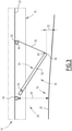
- the protection device 30 is more precisely visible on the figure 2 and 3 .
- the protection device 30 comprises: a flap 34; a strip 36 of flexible material 38; a winder 40; a motor 42; a first sensor 44; and a computer 46.
- the protection device 30 further comprises a second sensor 48.
- the flap 34, the retractor 40, the strip 36 of flexible material, the first 44 and the second 48 sensors are fixed to the lower surface 24 of the front part 22 of the box 16 in order to be arranged in the space lower 26.
- the flap 34 is rotatably mounted relative to the front part 22 of the body 16, along a first axis 50 parallel to Y.
- the flap 34 has a first 52 and a second 54 opposite edges, respectively near and far from the first axis 50.
- the flap 34 is materialized by bars 56, 58. More specifically, the flap 34 comprises two longitudinal bars 56 and at least one transverse bar 58.
- the longitudinal bars 56 are arranged on either side of a median plane (X, Z) of the railway vehicle 10. A first end of each of the longitudinal bars 56 is hinged to the body 16 along the first axis 50, said first ends forming the first edge 52 of the flap 34.
- the transverse bar 58 is arranged along Y and is fixed to a second end of each of the longitudinal bars 56.
- the transverse bar 58 materializes the second edge 54 of the flap 34.
- the strip 36 of flexible material 38 has a substantially rectangular shape, extending between a first 60 and a second end.
- the first end 60 of said strip 36 of flexible material is fixed to the transverse bar 58 of the flap 34.
- the first end 60 of the strip 36 is free to rotate relative to the transverse bar 58.
- the first end 60 of the strip 36 is integral with said transverse bar 58.
- the flexible material 38 is flexible, but non-stretchable.
- the flexible material 38 is a textile material, chosen in particular for its breaking strength. More preferably, the flexible material 38 is a textile material comprising Kevlar fibers.
- the reel 40 is rotatably mounted with respect to the front part 22 of the body 16, along a second axis 62 parallel to Y.
- the second axis 62 is located at the front of the rail vehicle 10 with respect to the first axis 50 rotation of flap 34.
- the second end (not shown) of strip 36 of flexible material 38 is attached to reel 40.
- the motor 42 is connected to the winder 40. As will be described later, the motor 42 is intended to rotate the winder 40 relative to the body 16 along the second axis 62, so as to wind or unroll the strip 36 of flexible material around said reel.
- the first sensor 44 is fixed under the front part 22 of the body 16, so as to measure a first distance 64 between said front part 22 and the ground located under the railway vehicle 10.
- the first sensor 44 is aligned along X with at least one wheel 19 of the bogie 18.
- the first distance 64 is measured between the front part 22 of the body 16 and a first rail 20.
- the second sensor 48 is fixed under the front part 22 of the body 16, so as to measure a second distance 66 between said front part 22 and the ground located under the railway vehicle 10.
- the first 44 and second 48 sensors are substantially identical.
- Said sensors are, for example, distance sensors of the lidar type.
- the first 44 and second 48 sensors are located facing each other with respect to the median plane (X, Z) of the railway vehicle 10. More preferably, each of the first 44 and second 48 sensors is aligned along X with a wheel 19 of bogie 18. Thus, the second distance 66 is measured between the front part 22 of the body 16 and a second rail 20, parallel to the first rail.
- each of the first 44 and second 48 sensors is fixed to the front part 22 of the body 16, behind with respect to the first axis 50 of rotation of the flap 34. More preferentially, the first 44 and second 48 sensors are located near along X of said first axis 50.
- the first 44 and second 48 sensors are located close along X to the first end 60 of the strip 36.
- the protection device comprises a third sensor centered on the vehicle, for example included in the median plane (X, Z). Such a third sensor makes it possible, in the case of strong curvature of the rails, to measure in all circumstances the shortest distance between the vehicle and the ground.
- the computer 46 is on board the railway vehicle 10. Said computer 46 is electronically connected, on the one hand to the first 44 and second 46 sensors, and on the other hand to the motor 42. As will be detailed later, the computer 46 is able to determine an angular arrangement of the reel 40 as a function of the first 64 and/or the second 66 distance measured by the first 44 or by the second 48 sensor.
- the protection device 30 described above allows the flap 34 to pivot relative to the body 16 in the lower space 26.
- figure 1 and 2 on the one hand, and picture 3 on the other hand represent the flap 34 in a first and in a second different angular positions, corresponding to a first and a second configuration of the protection device 30.
- the rails 20 located under the front part 22 of the body 16 extend substantially horizontally.
- the picture 3 represents the railway vehicle 10 while the front part 22 reaches the start 70 of a slope. In the example shown, it is a downward slope.
- the second edge 54 of the flap 34 is arranged forward relative to the first edge 52, in the direction X.
- the second edge 54 of flap 34 is arranged lower than retractor 40 in direction Z.
- the second edge 54 of the flap i.e. the transverse bar 58, has a non-zero spacing 72 with the rails 20 in the direction Z.
- Said spacing 72 is substantially identical in the first and in the the second setup.
- the non-zero spacing 72 is chosen to be sufficiently small to prevent an obstacle 32, such as a human body lying on the rails 20, from passing under the flap 34 during the movement of the railway vehicle 10
- the spacing 72 is chosen sufficiently large to avoid friction of the flap 34 against the ground and/or contact with small objects of the gravel type, located between the rails 20.
- the second edge 54 of the flap 34 is closer along Z to the winder 40 than in the second configuration of the picture 3 .
- the retractor 40 has respectively a first and a second angular disposition, different from each other.
- a length of the strip 36 wound on the winder 40 is greater in the first configuration of the figure 1 and 2 than in the second configuration of the picture 3 .
- the protection device 30 further comprises a deactivation member (not shown), for example in the form of a control button connected to the computer 46.
- Said control button is for example integrated into a control console located in the lead car 12.
- the actuation of the deactivation member causes the winding of the strip 36 so as to place the flap 34 in a retracted position.
- the transverse bar 58 is at a minimum distance from the lower surface 24 of the front part of the box 16.
- Such a deactivation member notably allows an operator to inhibit the protection device 30 in the event of unfavorable external conditions, for example in the event of flooding or heavy snowfall.
- the railway vehicle 10 runs on substantially horizontal rails 20, the protection device 30 being in the first configuration of the figure 1 .
- a portion of the strip 36 of flexible material 38 is deployed between the retractor 40 and the crossbar 58 of the flap 34, another part of said strip being wound around the retractor 40.
- the weight of the crossbar 58 keeps the unwound part of the strip 36 of flexible material taut.
- each of said sensors measures an initial value of the first 64 or the second 66 distance.
- Said initial value communicated to the computer 46, enables said computer to determine the angular disposition of the reel 40, so as to maintain the spacing 72 between the second edge 54 of the flap and the rails 20.
- the angular position of the flap 34 is determined by the length of the extended portion of the band 36.
- the computer 46 when the computer 46 receives the values of the first 64 and second 66 distances, said computer performs an average of said values to deduce therefrom the angular disposition of the reel 40.
- Such an embodiment makes it possible, for example, to take account height differences between the two rails 20.
- the computer 46 only takes account of the value supplied by the sensor in operation.
- the transverse bar 58 comes into contact with said obstacle 32.
- the strip 36 of flexible material 38 retains said obstacle 32 and prevents it from coming into contact with the wheels 19 of the bogie. 18.
- the force exerted by the obstacle 32 on the strip 36 causes the reel 40 to unwind. 19.
- the protection device 30 is configured so that the impact of the obstacle 32 is detected, for example at the level of the shutter 34 or of the retractor 40, and triggers an emergency braking device of the railway vehicle. 10.
- said first or second sensor measures a new value of the first 64 and/or the second 66 distance, different from the value initial. In the case illustrated in the picture 3 , the new value is greater than the initial value.
- the new value of the first 64 and/or the second 66 distance is communicated to the computer 46 by the first 44 and/or by the second 48 sensors.
- Said computer 46 determines a new angular arrangement of the roller 40 capable of maintaining the spacing 72 between the second edge 54 of the shutter and the rails 20.
- the computer 46 then actuates the motor 42 to set the winder 40 in rotation, so as to wind or unwind the strip 36 of the appropriate length. In the case illustrated in the picture 3 , the strip 36 is unwound.
- the band 36 is rolled up and the flap 34 pivots upwards, driven by the first end 60 of said band.
- the protection device 30 maintains a substantially constant spacing 72 with the rails 20, so as to effectively protect a pedestrian in front the railway vehicle 10.
- the positioning of the first 44 and second 48 sensors, behind the flap 34 prevents said sensors from being vertically above an obstacle 32 before said obstacle is brought into contact with the flap 34.
- the device protection 30 is not misled by such an obstacle, as regards the distance 64.66 with the rails 20.
- Tramway tracks generally meet standards associated with slopes of limited steepness.
- the computer 46 it is possible to configure the computer 46 to allow the protection device 30 to anticipate the variations in slope of the rails 20.
- said protection device 30 is capable of maintaining the spacing 72 included in a range centered on a nominal value, said nominal value being stored in the computer 46.
- the motor 42 is chosen with a maximum speed compatible with the maximum slopes of the rails and with a maximum speed of the railway vehicle 10
- said device is calibrated to adjust the nominal value of the spacing 72.
- the optimal nominal value can vary according to factors such as the load of the vehicle 10, wear of the wheels 19 or possible snow cover on the tracks.
Landscapes
- Engineering & Computer Science (AREA)
- Mechanical Engineering (AREA)
- Train Traffic Observation, Control, And Security (AREA)
- Operating, Guiding And Securing Of Roll- Type Closing Members (AREA)
- Vehicle Body Suspensions (AREA)
Applications Claiming Priority (1)
| Application Number | Priority Date | Filing Date | Title |
|---|---|---|---|
| FR2007949A FR3113018B1 (fr) | 2020-07-28 | 2020-07-28 | Dispositif de protection pour véhicule terrestre |
Publications (2)
| Publication Number | Publication Date |
|---|---|
| EP3945005A1 true EP3945005A1 (de) | 2022-02-02 |
| EP3945005B1 EP3945005B1 (de) | 2022-10-19 |
Family
ID=73013673
Family Applications (1)
| Application Number | Title | Priority Date | Filing Date |
|---|---|---|---|
| EP21187994.5A Active EP3945005B1 (de) | 2020-07-28 | 2021-07-27 | Schutzvorrichtung für landfahrzeug |
Country Status (5)
| Country | Link |
|---|---|
| EP (1) | EP3945005B1 (de) |
| AU (1) | AU2021206851A1 (de) |
| CA (1) | CA3125678A1 (de) |
| ES (1) | ES2935501T3 (de) |
| FR (1) | FR3113018B1 (de) |
Citations (3)
| Publication number | Priority date | Publication date | Assignee | Title |
|---|---|---|---|---|
| DE97920C (de) * | 1897-08-19 | 1898-06-28 | ||
| US1893634A (en) * | 1931-05-25 | 1933-01-10 | Roch Despatis | Safety device for vehicles |
| DE20002278U1 (de) | 2000-02-09 | 2001-06-21 | Siemens Duewag Schienenfahrzeuge GmbH, 47829 Krefeld | Schienenfahrzeug, insbesondere Straßen- oder Stadtbahnwagen für den Nahverkehr |
-
2020
- 2020-07-28 FR FR2007949A patent/FR3113018B1/fr active Active
-
2021
- 2021-07-22 CA CA3125678A patent/CA3125678A1/fr active Pending
- 2021-07-22 AU AU2021206851A patent/AU2021206851A1/en not_active Abandoned
- 2021-07-27 ES ES21187994T patent/ES2935501T3/es active Active
- 2021-07-27 EP EP21187994.5A patent/EP3945005B1/de active Active
Patent Citations (3)
| Publication number | Priority date | Publication date | Assignee | Title |
|---|---|---|---|---|
| DE97920C (de) * | 1897-08-19 | 1898-06-28 | ||
| US1893634A (en) * | 1931-05-25 | 1933-01-10 | Roch Despatis | Safety device for vehicles |
| DE20002278U1 (de) | 2000-02-09 | 2001-06-21 | Siemens Duewag Schienenfahrzeuge GmbH, 47829 Krefeld | Schienenfahrzeug, insbesondere Straßen- oder Stadtbahnwagen für den Nahverkehr |
Also Published As
| Publication number | Publication date |
|---|---|
| EP3945005B1 (de) | 2022-10-19 |
| CA3125678A1 (fr) | 2022-01-28 |
| FR3113018B1 (fr) | 2022-08-05 |
| ES2935501T3 (es) | 2023-03-07 |
| AU2021206851A1 (en) | 2022-02-17 |
| FR3113018A1 (fr) | 2022-02-04 |
Similar Documents
| Publication | Publication Date | Title |
|---|---|---|
| EP2544979B1 (de) | Vorrichtung zur festkeilung eines frachttransportfahrzeuges entlang eines docks, installation und verfahren | |
| EP0960844B1 (de) | Autonomer und automatischer Keil als Wegfahrsperre für Fahrzeuge und eine modulare Sperrvorrichtung unter Verwendung dieses Keils | |
| EP0061959A1 (de) | Anhänger mit drehbarer und beweglicher Bühne zum Transport von Fahrzeugen | |
| EP2089302B1 (de) | Schuh zum stillstand eines rades und motorisierte stillstandanordnung | |
| EP3018023B1 (de) | Schienenfahrzeug mit integrierter hinderungsvorrichtung, und entsprechendes verfahren | |
| EP0575248B1 (de) | Stromabnehmer-Vorrichtung für Fahrzeuge, insbesondere für Überleitungsbusse oder Stadtbahnwagen | |
| CA1179413A (fr) | Procede et dispositif pour la detection du sous- gonflage d'un pneumatique d'un atterrisseur d'aeronef | |
| EP3945005B1 (de) | Schutzvorrichtung für landfahrzeug | |
| EP2845835B1 (de) | Hebevorrichtung | |
| FR2897038A1 (fr) | Dispositif aerodynamique pour vehicule | |
| CA3196997A1 (fr) | Dispositif et systeme de largage, de maintien en vol et de recuperation d'un aerostat captif | |
| FR2602191A1 (fr) | Dispositif de surete et de signalisation pour hayons mobiles de camion | |
| EP3753799B1 (de) | Schutzvorrichtung für schienenfahrzeug | |
| EP3511213B1 (de) | Schienenfahrzeug, das eine not-bremsvorrichtung umfasst | |
| WO2017118823A1 (fr) | Chariot-portoir pour brancard | |
| WO2021043752A1 (fr) | Dispositif de protection pour véhicule ferroviaire | |
| FR2901515A1 (fr) | Vehicule de transport pourvu de moyens d'acces pour personnes a mobilite reduite | |
| FR3149247A1 (fr) | Vehicule automobile avec support de cable de recharge de batterie integre au retroviseur exterieur | |
| EP3604077B1 (de) | Schienenfahrzeug, das ein sicherheitssystem umfasst, das im falle einer kollision reagiert | |
| FR2896212A1 (fr) | Dispositif d'absorption d'energie en cas de choc pour vehicule automobile. | |
| FR2857638A1 (fr) | Dispositif de relevage d'un moyen de protection arriere d'un vehicule industriel et vehicule industriel equipe d'un tel dispositif | |
| WO2024246442A1 (fr) | Vehicule automobile avec crochet de support de cable de recharge de la batterie de traction | |
| FR3133667A1 (fr) | codeur à câble perfectionné | |
| FR2862929A1 (fr) | Dispositif de freinage pour vehicule automobile | |
| FR2815361A1 (fr) | Dispositif d'arret coercitif d'un vehicule automobile monte sur pneumatiques |
Legal Events
| Date | Code | Title | Description |
|---|---|---|---|
| PUAI | Public reference made under article 153(3) epc to a published international application that has entered the european phase |
Free format text: ORIGINAL CODE: 0009012 |
|
| STAA | Information on the status of an ep patent application or granted ep patent |
Free format text: STATUS: THE APPLICATION HAS BEEN PUBLISHED |
|
| STAA | Information on the status of an ep patent application or granted ep patent |
Free format text: STATUS: REQUEST FOR EXAMINATION WAS MADE |
|
| AK | Designated contracting states |
Kind code of ref document: A1 Designated state(s): AL AT BE BG CH CY CZ DE DK EE ES FI FR GB GR HR HU IE IS IT LI LT LU LV MC MK MT NL NO PL PT RO RS SE SI SK SM TR |
|
| 17P | Request for examination filed |
Effective date: 20220118 |
|
| RBV | Designated contracting states (corrected) |
Designated state(s): AL AT BE BG CH CY CZ DE DK EE ES FI FR GB GR HR HU IE IS IT LI LT LU LV MC MK MT NL NO PL PT RO RS SE SI SK SM TR |
|
| GRAP | Despatch of communication of intention to grant a patent |
Free format text: ORIGINAL CODE: EPIDOSNIGR1 |
|
| STAA | Information on the status of an ep patent application or granted ep patent |
Free format text: STATUS: GRANT OF PATENT IS INTENDED |
|
| RIC1 | Information provided on ipc code assigned before grant |
Ipc: B61F 19/08 20060101AFI20220506BHEP |
|
| INTG | Intention to grant announced |
Effective date: 20220531 |
|
| GRAS | Grant fee paid |
Free format text: ORIGINAL CODE: EPIDOSNIGR3 |
|
| GRAA | (expected) grant |
Free format text: ORIGINAL CODE: 0009210 |
|
| STAA | Information on the status of an ep patent application or granted ep patent |
Free format text: STATUS: THE PATENT HAS BEEN GRANTED |
|
| AK | Designated contracting states |
Kind code of ref document: B1 Designated state(s): AL AT BE BG CH CY CZ DE DK EE ES FI FR GB GR HR HU IE IS IT LI LT LU LV MC MK MT NL NO PL PT RO RS SE SI SK SM TR |
|
| REG | Reference to a national code |
Ref country code: GB Ref legal event code: FG4D Free format text: NOT ENGLISH |
|
| RIN1 | Information on inventor provided before grant (corrected) |
Inventor name: AYME, NICOLAS |
|
| REG | Reference to a national code |
Ref country code: CH Ref legal event code: EP |
|
| REG | Reference to a national code |
Ref country code: IE Ref legal event code: FG4D Free format text: LANGUAGE OF EP DOCUMENT: FRENCH |
|
| REG | Reference to a national code |
Ref country code: DE Ref legal event code: R096 Ref document number: 602021000587 Country of ref document: DE |
|
| REG | Reference to a national code |
Ref country code: AT Ref legal event code: REF Ref document number: 1525389 Country of ref document: AT Kind code of ref document: T Effective date: 20221115 |
|
| REG | Reference to a national code |
Ref country code: LT Ref legal event code: MG9D |
|
| REG | Reference to a national code |
Ref country code: NL Ref legal event code: MP Effective date: 20221019 |
|
| REG | Reference to a national code |
Ref country code: ES Ref legal event code: FG2A Ref document number: 2935501 Country of ref document: ES Kind code of ref document: T3 Effective date: 20230307 |
|
| REG | Reference to a national code |
Ref country code: AT Ref legal event code: MK05 Ref document number: 1525389 Country of ref document: AT Kind code of ref document: T Effective date: 20221019 |
|
| PG25 | Lapsed in a contracting state [announced via postgrant information from national office to epo] |
Ref country code: NL Free format text: LAPSE BECAUSE OF FAILURE TO SUBMIT A TRANSLATION OF THE DESCRIPTION OR TO PAY THE FEE WITHIN THE PRESCRIBED TIME-LIMIT Effective date: 20221019 |
|
| PG25 | Lapsed in a contracting state [announced via postgrant information from national office to epo] |
Ref country code: SE Free format text: LAPSE BECAUSE OF FAILURE TO SUBMIT A TRANSLATION OF THE DESCRIPTION OR TO PAY THE FEE WITHIN THE PRESCRIBED TIME-LIMIT Effective date: 20221019 Ref country code: PT Free format text: LAPSE BECAUSE OF FAILURE TO SUBMIT A TRANSLATION OF THE DESCRIPTION OR TO PAY THE FEE WITHIN THE PRESCRIBED TIME-LIMIT Effective date: 20230220 Ref country code: NO Free format text: LAPSE BECAUSE OF FAILURE TO SUBMIT A TRANSLATION OF THE DESCRIPTION OR TO PAY THE FEE WITHIN THE PRESCRIBED TIME-LIMIT Effective date: 20230119 Ref country code: LT Free format text: LAPSE BECAUSE OF FAILURE TO SUBMIT A TRANSLATION OF THE DESCRIPTION OR TO PAY THE FEE WITHIN THE PRESCRIBED TIME-LIMIT Effective date: 20221019 Ref country code: FI Free format text: LAPSE BECAUSE OF FAILURE TO SUBMIT A TRANSLATION OF THE DESCRIPTION OR TO PAY THE FEE WITHIN THE PRESCRIBED TIME-LIMIT Effective date: 20221019 Ref country code: AT Free format text: LAPSE BECAUSE OF FAILURE TO SUBMIT A TRANSLATION OF THE DESCRIPTION OR TO PAY THE FEE WITHIN THE PRESCRIBED TIME-LIMIT Effective date: 20221019 |
|
| PG25 | Lapsed in a contracting state [announced via postgrant information from national office to epo] |
Ref country code: RS Free format text: LAPSE BECAUSE OF FAILURE TO SUBMIT A TRANSLATION OF THE DESCRIPTION OR TO PAY THE FEE WITHIN THE PRESCRIBED TIME-LIMIT Effective date: 20221019 Ref country code: PL Free format text: LAPSE BECAUSE OF FAILURE TO SUBMIT A TRANSLATION OF THE DESCRIPTION OR TO PAY THE FEE WITHIN THE PRESCRIBED TIME-LIMIT Effective date: 20221019 Ref country code: LV Free format text: LAPSE BECAUSE OF FAILURE TO SUBMIT A TRANSLATION OF THE DESCRIPTION OR TO PAY THE FEE WITHIN THE PRESCRIBED TIME-LIMIT Effective date: 20221019 Ref country code: IS Free format text: LAPSE BECAUSE OF FAILURE TO SUBMIT A TRANSLATION OF THE DESCRIPTION OR TO PAY THE FEE WITHIN THE PRESCRIBED TIME-LIMIT Effective date: 20230219 Ref country code: HR Free format text: LAPSE BECAUSE OF FAILURE TO SUBMIT A TRANSLATION OF THE DESCRIPTION OR TO PAY THE FEE WITHIN THE PRESCRIBED TIME-LIMIT Effective date: 20221019 Ref country code: GR Free format text: LAPSE BECAUSE OF FAILURE TO SUBMIT A TRANSLATION OF THE DESCRIPTION OR TO PAY THE FEE WITHIN THE PRESCRIBED TIME-LIMIT Effective date: 20230120 |
|
| REG | Reference to a national code |
Ref country code: DE Ref legal event code: R097 Ref document number: 602021000587 Country of ref document: DE |
|
| PG25 | Lapsed in a contracting state [announced via postgrant information from national office to epo] |
Ref country code: SM Free format text: LAPSE BECAUSE OF FAILURE TO SUBMIT A TRANSLATION OF THE DESCRIPTION OR TO PAY THE FEE WITHIN THE PRESCRIBED TIME-LIMIT Effective date: 20221019 Ref country code: RO Free format text: LAPSE BECAUSE OF FAILURE TO SUBMIT A TRANSLATION OF THE DESCRIPTION OR TO PAY THE FEE WITHIN THE PRESCRIBED TIME-LIMIT Effective date: 20221019 Ref country code: EE Free format text: LAPSE BECAUSE OF FAILURE TO SUBMIT A TRANSLATION OF THE DESCRIPTION OR TO PAY THE FEE WITHIN THE PRESCRIBED TIME-LIMIT Effective date: 20221019 Ref country code: DK Free format text: LAPSE BECAUSE OF FAILURE TO SUBMIT A TRANSLATION OF THE DESCRIPTION OR TO PAY THE FEE WITHIN THE PRESCRIBED TIME-LIMIT Effective date: 20221019 Ref country code: CZ Free format text: LAPSE BECAUSE OF FAILURE TO SUBMIT A TRANSLATION OF THE DESCRIPTION OR TO PAY THE FEE WITHIN THE PRESCRIBED TIME-LIMIT Effective date: 20221019 |
|
| PLBE | No opposition filed within time limit |
Free format text: ORIGINAL CODE: 0009261 |
|
| STAA | Information on the status of an ep patent application or granted ep patent |
Free format text: STATUS: NO OPPOSITION FILED WITHIN TIME LIMIT |
|
| PG25 | Lapsed in a contracting state [announced via postgrant information from national office to epo] |
Ref country code: SK Free format text: LAPSE BECAUSE OF FAILURE TO SUBMIT A TRANSLATION OF THE DESCRIPTION OR TO PAY THE FEE WITHIN THE PRESCRIBED TIME-LIMIT Effective date: 20221019 Ref country code: AL Free format text: LAPSE BECAUSE OF FAILURE TO SUBMIT A TRANSLATION OF THE DESCRIPTION OR TO PAY THE FEE WITHIN THE PRESCRIBED TIME-LIMIT Effective date: 20221019 |
|
| 26N | No opposition filed |
Effective date: 20230720 |
|
| P01 | Opt-out of the competence of the unified patent court (upc) registered |
Effective date: 20230823 |
|
| PG25 | Lapsed in a contracting state [announced via postgrant information from national office to epo] |
Ref country code: SI Free format text: LAPSE BECAUSE OF FAILURE TO SUBMIT A TRANSLATION OF THE DESCRIPTION OR TO PAY THE FEE WITHIN THE PRESCRIBED TIME-LIMIT Effective date: 20221019 |
|
| PG25 | Lapsed in a contracting state [announced via postgrant information from national office to epo] |
Ref country code: MC Free format text: LAPSE BECAUSE OF FAILURE TO SUBMIT A TRANSLATION OF THE DESCRIPTION OR TO PAY THE FEE WITHIN THE PRESCRIBED TIME-LIMIT Effective date: 20221019 |
|
| PG25 | Lapsed in a contracting state [announced via postgrant information from national office to epo] |
Ref country code: MC Free format text: LAPSE BECAUSE OF FAILURE TO SUBMIT A TRANSLATION OF THE DESCRIPTION OR TO PAY THE FEE WITHIN THE PRESCRIBED TIME-LIMIT Effective date: 20221019 |
|
| REG | Reference to a national code |
Ref country code: BE Ref legal event code: MM Effective date: 20230731 |
|
| PG25 | Lapsed in a contracting state [announced via postgrant information from national office to epo] |
Ref country code: LU Free format text: LAPSE BECAUSE OF NON-PAYMENT OF DUE FEES Effective date: 20230727 |
|
| PG25 | Lapsed in a contracting state [announced via postgrant information from national office to epo] |
Ref country code: LU Free format text: LAPSE BECAUSE OF NON-PAYMENT OF DUE FEES Effective date: 20230727 |
|
| REG | Reference to a national code |
Ref country code: IE Ref legal event code: MM4A |
|
| PG25 | Lapsed in a contracting state [announced via postgrant information from national office to epo] |
Ref country code: IT Free format text: LAPSE BECAUSE OF FAILURE TO SUBMIT A TRANSLATION OF THE DESCRIPTION OR TO PAY THE FEE WITHIN THE PRESCRIBED TIME-LIMIT Effective date: 20221019 Ref country code: BE Free format text: LAPSE BECAUSE OF NON-PAYMENT OF DUE FEES Effective date: 20230731 |
|
| PG25 | Lapsed in a contracting state [announced via postgrant information from national office to epo] |
Ref country code: IE Free format text: LAPSE BECAUSE OF NON-PAYMENT OF DUE FEES Effective date: 20230727 |
|
| PG25 | Lapsed in a contracting state [announced via postgrant information from national office to epo] |
Ref country code: IE Free format text: LAPSE BECAUSE OF NON-PAYMENT OF DUE FEES Effective date: 20230727 |
|
| PG25 | Lapsed in a contracting state [announced via postgrant information from national office to epo] |
Ref country code: BG Free format text: LAPSE BECAUSE OF FAILURE TO SUBMIT A TRANSLATION OF THE DESCRIPTION OR TO PAY THE FEE WITHIN THE PRESCRIBED TIME-LIMIT Effective date: 20221019 |
|
| PG25 | Lapsed in a contracting state [announced via postgrant information from national office to epo] |
Ref country code: BG Free format text: LAPSE BECAUSE OF FAILURE TO SUBMIT A TRANSLATION OF THE DESCRIPTION OR TO PAY THE FEE WITHIN THE PRESCRIBED TIME-LIMIT Effective date: 20221019 |
|
| REG | Reference to a national code |
Ref country code: ES Ref legal event code: PC2A Owner name: ALSTOM HOLDINGS Effective date: 20250310 |
|
| PG25 | Lapsed in a contracting state [announced via postgrant information from national office to epo] |
Ref country code: CY Free format text: LAPSE BECAUSE OF FAILURE TO SUBMIT A TRANSLATION OF THE DESCRIPTION OR TO PAY THE FEE WITHIN THE PRESCRIBED TIME-LIMIT; INVALID AB INITIO Effective date: 20210727 |
|
| PG25 | Lapsed in a contracting state [announced via postgrant information from national office to epo] |
Ref country code: HU Free format text: LAPSE BECAUSE OF FAILURE TO SUBMIT A TRANSLATION OF THE DESCRIPTION OR TO PAY THE FEE WITHIN THE PRESCRIBED TIME-LIMIT; INVALID AB INITIO Effective date: 20210727 |
|
| PGFP | Annual fee paid to national office [announced via postgrant information from national office to epo] |
Ref country code: ES Payment date: 20250827 Year of fee payment: 5 |
|
| PGFP | Annual fee paid to national office [announced via postgrant information from national office to epo] |
Ref country code: DE Payment date: 20250722 Year of fee payment: 5 |
|
| PGFP | Annual fee paid to national office [announced via postgrant information from national office to epo] |
Ref country code: FR Payment date: 20250725 Year of fee payment: 5 |
|
| PGFP | Annual fee paid to national office [announced via postgrant information from national office to epo] |
Ref country code: CH Payment date: 20250801 Year of fee payment: 5 |
|
| PG25 | Lapsed in a contracting state [announced via postgrant information from national office to epo] |
Ref country code: TR Free format text: LAPSE BECAUSE OF FAILURE TO SUBMIT A TRANSLATION OF THE DESCRIPTION OR TO PAY THE FEE WITHIN THE PRESCRIBED TIME-LIMIT Effective date: 20221019 |
|
| GBPC | Gb: european patent ceased through non-payment of renewal fee |
Effective date: 20250727 |
|
| PG25 | Lapsed in a contracting state [announced via postgrant information from national office to epo] |
Ref country code: GB Free format text: LAPSE BECAUSE OF NON-PAYMENT OF DUE FEES Effective date: 20250727 |