EP3945071A2 - Procédé de traitement des eaux destiné à l'élimination des polluants, installation de traitement des eaux correspondante, ainsi qu'élément rapporté de distribution - Google Patents
Procédé de traitement des eaux destiné à l'élimination des polluants, installation de traitement des eaux correspondante, ainsi qu'élément rapporté de distribution Download PDFInfo
- Publication number
- EP3945071A2 EP3945071A2 EP21020394.9A EP21020394A EP3945071A2 EP 3945071 A2 EP3945071 A2 EP 3945071A2 EP 21020394 A EP21020394 A EP 21020394A EP 3945071 A2 EP3945071 A2 EP 3945071A2
- Authority
- EP
- European Patent Office
- Prior art keywords
- water
- removal device
- container
- agglomerates
- water treatment
- Prior art date
- Legal status (The legal status is an assumption and is not a legal conclusion. Google has not performed a legal analysis and makes no representation as to the accuracy of the status listed.)
- Withdrawn
Links
- XLYOFNOQVPJJNP-UHFFFAOYSA-N water Substances O XLYOFNOQVPJJNP-UHFFFAOYSA-N 0.000 title claims abstract description 118
- 238000000034 method Methods 0.000 title claims abstract description 54
- 239000003344 environmental pollutant Substances 0.000 title claims abstract description 6
- 231100000719 pollutant Toxicity 0.000 title claims abstract description 6
- 238000000605 extraction Methods 0.000 title claims description 7
- 230000008569 process Effects 0.000 claims abstract description 21
- 239000000463 material Substances 0.000 claims description 21
- 238000002156 mixing Methods 0.000 claims description 18
- 229920000426 Microplastic Polymers 0.000 claims description 15
- 239000000654 additive Substances 0.000 claims description 12
- 230000000996 additive effect Effects 0.000 claims description 9
- 238000000926 separation method Methods 0.000 claims description 9
- RMAQACBXLXPBSY-UHFFFAOYSA-N silicic acid Chemical compound O[Si](O)(O)O RMAQACBXLXPBSY-UHFFFAOYSA-N 0.000 claims description 9
- 235000012239 silicon dioxide Nutrition 0.000 claims description 9
- 238000011049 filling Methods 0.000 claims description 7
- 230000004807 localization Effects 0.000 claims description 6
- 238000003756 stirring Methods 0.000 claims description 6
- 239000000706 filtrate Substances 0.000 claims description 4
- 230000009466 transformation Effects 0.000 claims description 4
- 238000009423 ventilation Methods 0.000 claims description 4
- 230000004888 barrier function Effects 0.000 claims description 3
- 239000008213 purified water Substances 0.000 claims description 3
- 239000012141 concentrate Substances 0.000 claims 1
- 238000010297 mechanical methods and process Methods 0.000 claims 1
- 230000005226 mechanical processes and functions Effects 0.000 claims 1
- VYPSYNLAJGMNEJ-UHFFFAOYSA-N Silicium dioxide Chemical compound O=[Si]=O VYPSYNLAJGMNEJ-UHFFFAOYSA-N 0.000 description 17
- 239000007788 liquid Substances 0.000 description 13
- 239000000377 silicon dioxide Substances 0.000 description 7
- 238000005273 aeration Methods 0.000 description 6
- 230000015572 biosynthetic process Effects 0.000 description 6
- 239000002245 particle Substances 0.000 description 6
- 238000012216 screening Methods 0.000 description 4
- 239000000126 substance Substances 0.000 description 4
- 238000010924 continuous production Methods 0.000 description 3
- 238000009826 distribution Methods 0.000 description 3
- 230000000694 effects Effects 0.000 description 3
- 238000009434 installation Methods 0.000 description 3
- 238000012544 monitoring process Methods 0.000 description 3
- 239000002351 wastewater Substances 0.000 description 3
- 238000005352 clarification Methods 0.000 description 2
- 238000004140 cleaning Methods 0.000 description 2
- 239000006260 foam Substances 0.000 description 2
- 229920003023 plastic Polymers 0.000 description 2
- 239000004033 plastic Substances 0.000 description 2
- 230000010349 pulsation Effects 0.000 description 2
- 238000000746 purification Methods 0.000 description 2
- 239000000741 silica gel Substances 0.000 description 2
- 229910002027 silica gel Inorganic materials 0.000 description 2
- 239000007787 solid Substances 0.000 description 2
- 238000012546 transfer Methods 0.000 description 2
- XUIMIQQOPSSXEZ-UHFFFAOYSA-N Silicon Chemical compound [Si] XUIMIQQOPSSXEZ-UHFFFAOYSA-N 0.000 description 1
- 208000007536 Thrombosis Diseases 0.000 description 1
- 238000005054 agglomeration Methods 0.000 description 1
- 230000002776 aggregation Effects 0.000 description 1
- 230000008901 benefit Effects 0.000 description 1
- 230000033228 biological regulation Effects 0.000 description 1
- 238000007664 blowing Methods 0.000 description 1
- 239000003054 catalyst Substances 0.000 description 1
- 238000002144 chemical decomposition reaction Methods 0.000 description 1
- 239000007795 chemical reaction product Substances 0.000 description 1
- 239000011362 coarse particle Substances 0.000 description 1
- 238000010276 construction Methods 0.000 description 1
- 239000000356 contaminant Substances 0.000 description 1
- 238000011437 continuous method Methods 0.000 description 1
- 229920003020 cross-linked polyethylene Polymers 0.000 description 1
- 239000007857 degradation product Substances 0.000 description 1
- 230000001419 dependent effect Effects 0.000 description 1
- 238000009795 derivation Methods 0.000 description 1
- 238000013461 design Methods 0.000 description 1
- 238000006073 displacement reaction Methods 0.000 description 1
- 239000003814 drug Substances 0.000 description 1
- 238000005516 engineering process Methods 0.000 description 1
- 230000007613 environmental effect Effects 0.000 description 1
- 230000003203 everyday effect Effects 0.000 description 1
- 238000011010 flushing procedure Methods 0.000 description 1
- 125000000524 functional group Chemical group 0.000 description 1
- 239000011521 glass Substances 0.000 description 1
- 230000005484 gravity Effects 0.000 description 1
- 239000012535 impurity Substances 0.000 description 1
- 239000008235 industrial water Substances 0.000 description 1
- 230000010354 integration Effects 0.000 description 1
- 238000012423 maintenance Methods 0.000 description 1
- 238000010327 methods by industry Methods 0.000 description 1
- 230000002572 peristaltic effect Effects 0.000 description 1
- 239000000575 pesticide Substances 0.000 description 1
- 239000000546 pharmaceutical excipient Substances 0.000 description 1
- 230000010287 polarization Effects 0.000 description 1
- 239000000047 product Substances 0.000 description 1
- 230000029058 respiratory gaseous exchange Effects 0.000 description 1
- 238000005070 sampling Methods 0.000 description 1
- 239000004576 sand Substances 0.000 description 1
- 239000010865 sewage Substances 0.000 description 1
- 229910052710 silicon Inorganic materials 0.000 description 1
- 239000010703 silicon Substances 0.000 description 1
- 238000003466 welding Methods 0.000 description 1
Images





Classifications
-
- C—CHEMISTRY; METALLURGY
- C02—TREATMENT OF WATER, WASTE WATER, SEWAGE, OR SLUDGE
- C02F—TREATMENT OF WATER, WASTE WATER, SEWAGE, OR SLUDGE
- C02F1/00—Treatment of water, waste water, or sewage
- C02F1/24—Treatment of water, waste water, or sewage by flotation
-
- B—PERFORMING OPERATIONS; TRANSPORTING
- B01—PHYSICAL OR CHEMICAL PROCESSES OR APPARATUS IN GENERAL
- B01J—CHEMICAL OR PHYSICAL PROCESSES, e.g. CATALYSIS OR COLLOID CHEMISTRY; THEIR RELEVANT APPARATUS
- B01J19/00—Chemical, physical or physico-chemical processes in general; Their relevant apparatus
- B01J19/0053—Details of the reactor
- B01J19/006—Baffles
-
- B—PERFORMING OPERATIONS; TRANSPORTING
- B01—PHYSICAL OR CHEMICAL PROCESSES OR APPARATUS IN GENERAL
- B01J—CHEMICAL OR PHYSICAL PROCESSES, e.g. CATALYSIS OR COLLOID CHEMISTRY; THEIR RELEVANT APPARATUS
- B01J19/00—Chemical, physical or physico-chemical processes in general; Their relevant apparatus
- B01J19/0053—Details of the reactor
- B01J19/0066—Stirrers
-
- B—PERFORMING OPERATIONS; TRANSPORTING
- B01—PHYSICAL OR CHEMICAL PROCESSES OR APPARATUS IN GENERAL
- B01J—CHEMICAL OR PHYSICAL PROCESSES, e.g. CATALYSIS OR COLLOID CHEMISTRY; THEIR RELEVANT APPARATUS
- B01J4/00—Feed or outlet devices; Feed or outlet control devices
- B01J4/001—Feed or outlet devices as such, e.g. feeding tubes
- B01J4/005—Feed or outlet devices as such, e.g. feeding tubes provided with baffles
-
- B—PERFORMING OPERATIONS; TRANSPORTING
- B01—PHYSICAL OR CHEMICAL PROCESSES OR APPARATUS IN GENERAL
- B01J—CHEMICAL OR PHYSICAL PROCESSES, e.g. CATALYSIS OR COLLOID CHEMISTRY; THEIR RELEVANT APPARATUS
- B01J4/00—Feed or outlet devices; Feed or outlet control devices
- B01J4/02—Feed or outlet devices; Feed or outlet control devices for feeding measured, i.e. prescribed quantities of reagents
-
- B—PERFORMING OPERATIONS; TRANSPORTING
- B03—SEPARATION OF SOLID MATERIALS USING LIQUIDS OR USING PNEUMATIC TABLES OR JIGS; MAGNETIC OR ELECTROSTATIC SEPARATION OF SOLID MATERIALS FROM SOLID MATERIALS OR FLUIDS; SEPARATION BY HIGH-VOLTAGE ELECTRIC FIELDS
- B03D—FLOTATION; DIFFERENTIAL SEDIMENTATION
- B03D1/00—Flotation
- B03D1/14—Flotation machines
- B03D1/1412—Flotation machines with baffles, e.g. at the wall for redirecting settling solids
-
- B—PERFORMING OPERATIONS; TRANSPORTING
- B03—SEPARATION OF SOLID MATERIALS USING LIQUIDS OR USING PNEUMATIC TABLES OR JIGS; MAGNETIC OR ELECTROSTATIC SEPARATION OF SOLID MATERIALS FROM SOLID MATERIALS OR FLUIDS; SEPARATION BY HIGH-VOLTAGE ELECTRIC FIELDS
- B03D—FLOTATION; DIFFERENTIAL SEDIMENTATION
- B03D1/00—Flotation
- B03D1/14—Flotation machines
- B03D1/1418—Flotation machines using centrifugal forces
- B03D1/1425—Flotation machines using centrifugal forces air-sparged hydrocyclones
-
- B—PERFORMING OPERATIONS; TRANSPORTING
- B03—SEPARATION OF SOLID MATERIALS USING LIQUIDS OR USING PNEUMATIC TABLES OR JIGS; MAGNETIC OR ELECTROSTATIC SEPARATION OF SOLID MATERIALS FROM SOLID MATERIALS OR FLUIDS; SEPARATION BY HIGH-VOLTAGE ELECTRIC FIELDS
- B03D—FLOTATION; DIFFERENTIAL SEDIMENTATION
- B03D1/00—Flotation
- B03D1/14—Flotation machines
- B03D1/1443—Feed or discharge mechanisms for flotation tanks
- B03D1/145—Feed mechanisms for reagents
-
- B—PERFORMING OPERATIONS; TRANSPORTING
- B03—SEPARATION OF SOLID MATERIALS USING LIQUIDS OR USING PNEUMATIC TABLES OR JIGS; MAGNETIC OR ELECTROSTATIC SEPARATION OF SOLID MATERIALS FROM SOLID MATERIALS OR FLUIDS; SEPARATION BY HIGH-VOLTAGE ELECTRIC FIELDS
- B03D—FLOTATION; DIFFERENTIAL SEDIMENTATION
- B03D1/00—Flotation
- B03D1/14—Flotation machines
- B03D1/1443—Feed or discharge mechanisms for flotation tanks
- B03D1/1456—Feed mechanisms for the slurry
-
- B—PERFORMING OPERATIONS; TRANSPORTING
- B03—SEPARATION OF SOLID MATERIALS USING LIQUIDS OR USING PNEUMATIC TABLES OR JIGS; MAGNETIC OR ELECTROSTATIC SEPARATION OF SOLID MATERIALS FROM SOLID MATERIALS OR FLUIDS; SEPARATION BY HIGH-VOLTAGE ELECTRIC FIELDS
- B03D—FLOTATION; DIFFERENTIAL SEDIMENTATION
- B03D1/00—Flotation
- B03D1/14—Flotation machines
- B03D1/1443—Feed or discharge mechanisms for flotation tanks
- B03D1/1462—Discharge mechanisms for the froth
-
- B—PERFORMING OPERATIONS; TRANSPORTING
- B03—SEPARATION OF SOLID MATERIALS USING LIQUIDS OR USING PNEUMATIC TABLES OR JIGS; MAGNETIC OR ELECTROSTATIC SEPARATION OF SOLID MATERIALS FROM SOLID MATERIALS OR FLUIDS; SEPARATION BY HIGH-VOLTAGE ELECTRIC FIELDS
- B03D—FLOTATION; DIFFERENTIAL SEDIMENTATION
- B03D1/00—Flotation
- B03D1/14—Flotation machines
- B03D1/1443—Feed or discharge mechanisms for flotation tanks
- B03D1/1475—Flotation tanks having means for discharging the pulp, e.g. as a bleed stream
-
- B—PERFORMING OPERATIONS; TRANSPORTING
- B03—SEPARATION OF SOLID MATERIALS USING LIQUIDS OR USING PNEUMATIC TABLES OR JIGS; MAGNETIC OR ELECTROSTATIC SEPARATION OF SOLID MATERIALS FROM SOLID MATERIALS OR FLUIDS; SEPARATION BY HIGH-VOLTAGE ELECTRIC FIELDS
- B03D—FLOTATION; DIFFERENTIAL SEDIMENTATION
- B03D1/00—Flotation
- B03D1/14—Flotation machines
- B03D1/1493—Flotation machines with means for establishing a specified flow pattern
-
- C—CHEMISTRY; METALLURGY
- C02—TREATMENT OF WATER, WASTE WATER, SEWAGE, OR SLUDGE
- C02F—TREATMENT OF WATER, WASTE WATER, SEWAGE, OR SLUDGE
- C02F1/00—Treatment of water, waste water, or sewage
- C02F1/28—Treatment of water, waste water, or sewage by sorption
- C02F1/285—Treatment of water, waste water, or sewage by sorption using synthetic organic sorbents
-
- C—CHEMISTRY; METALLURGY
- C02—TREATMENT OF WATER, WASTE WATER, SEWAGE, OR SLUDGE
- C02F—TREATMENT OF WATER, WASTE WATER, SEWAGE, OR SLUDGE
- C02F1/00—Treatment of water, waste water, or sewage
- C02F1/52—Treatment of water, waste water, or sewage by flocculation or precipitation of suspended impurities
- C02F1/54—Treatment of water, waste water, or sewage by flocculation or precipitation of suspended impurities using organic material
- C02F1/545—Silicon compounds
-
- B—PERFORMING OPERATIONS; TRANSPORTING
- B03—SEPARATION OF SOLID MATERIALS USING LIQUIDS OR USING PNEUMATIC TABLES OR JIGS; MAGNETIC OR ELECTROSTATIC SEPARATION OF SOLID MATERIALS FROM SOLID MATERIALS OR FLUIDS; SEPARATION BY HIGH-VOLTAGE ELECTRIC FIELDS
- B03D—FLOTATION; DIFFERENTIAL SEDIMENTATION
- B03D2203/00—Specified materials treated by the flotation agents; Specified applications
- B03D2203/008—Water purification, e.g. for process water recycling
-
- C—CHEMISTRY; METALLURGY
- C02—TREATMENT OF WATER, WASTE WATER, SEWAGE, OR SLUDGE
- C02F—TREATMENT OF WATER, WASTE WATER, SEWAGE, OR SLUDGE
- C02F2301/00—General aspects of water treatment
- C02F2301/02—Fluid flow conditions
- C02F2301/026—Spiral, helicoidal, radial
Definitions
- the present invention relates to a water treatment method for removing pollutants, in particular microplastics, and a water treatment system for this, such as from WO 2019/219106 A1 known.
- the invention also relates to a removal insert for placing, screwing on or welding from above onto or into a container.
- hybrid inorganic-organic silica material is in WO 2019/219106 A1 described for the representation of a reaction product as an agglomerate from, among other things, microplastics and hybrid silica gel.
- an additive that forms agglomerates at least from the pollutants to be separated in particular an inorganic-organic hybrid silicic acid material, is metered into the water to be treated in order to form a rotating vortex in a mixing container.
- agglomerates are discharged by means of a removal device.
- the discharge device is inserted or placed on top of the mixing tank so that the rotating liquid can reach an overflow of the discharge device once its level reaches a discharge height.
- the agglomerates are removed from the rotating trombe upwards and to the side by means of the removal device.
- a hybrid molecule sold under the trade name PE-X/AB 523985 with a silicon-based backbone and organic functional groups is particularly preferably used, general molecular formula (RSiO m ) n .
- This material although liquid, has a viscous oily appearance.
- the specific gravity is 1.01 g/ml. It is insoluble in water.
- the invention addresses this with special dosing devices and flow guides in order to guarantee the best possible efficiency, even in water that is organically polluted and tends to foam.
- a water treatment plant for removing microplastics in particular from water to be cleaned with at least one mixing tank in whose upper tank area(s) concentrated agglomerates are separated in trombe(s).
- at least one removal device preferably a single removal device per container or a common removal device of several containers, is arranged horizontally aligned and inserted into the top of the container for knocking off the agglomerates.
- the removal device breaks through the respective container side wall of a stirred container or rotary separating container used as a mixing container, leading through a central overflow upwards (A) and sealed.
- conical guide plates are arranged in the upper part of the mixing container on the inside, preferably at the top of the upflow gap, clinging to the container side wall radially on the outside and supported radially on the inside by a support wall facing away from the circulating flow, avoiding flow turbulence as far as possible.
- At least one trough sloping towards the perforated container wall is arranged in the removal device, preferably two parallel troughs which are open at the top and toothed on the longitudinal sides facing an upflow gap running between the troughs.
- the agglomerate water (21) overflowing in the removal device(s) (20, 20', 20") is preferably fed to a single, in particular central, screen unit or to a plurality of screen units.
- a removal device is designed for a water treatment plant for the above-mentioned purpose if it causes the movement of the agglomerates rotating in the trombe to reverse in at least one radial direction outwards, as mentioned above after the movement has reversed at the end, preferably by at least one sloping channel.
- the relevant reversal of movement in the extraction device is initiated by accommodating the vortex in the geometry of an upflow gap or an upflow circle.
- the respective removal device catches the rotating agglomerates centrally in the gap or circle upflow and allows them to specifically pass over into a channel arrangement.
- a dosing device is arranged along the upflow gap, preferably integrated, in order not to impede an upward flow through the removal device or circular upflow during the upflow, particularly preferably as a rotatable tubular element to close off a guide plate or as a swiveling telescopic dosing rod.
- a ring is preferably formed with a particularly preferably vertically aligned wall, particularly preferably with a downwardly funnel-shaped, radially outwardly widened wall. At least on one side, the ring has an opening in the wall for the passage of agglomerate water into a groove designed to fall radially outwards.
- the removal device(s) or the common removal device is/are according to the invention each horizontally aligned on at least one side the respective container wall of a stirred tank or rotary separating tank used as a rotary container through a central overflow sealed or, for example, screwed or flanged sealingly.
- Preferred embodiments of such removal devices have overflow edges with a special geometry for influencing the upflow and overflow of an agglomerate fraction, which is also diverted to the width from the rotation upwards in the removal device.
- This process technology according to the invention is preferably used if the hybrid silicic acid material was metered into microplastic-contaminated clear or process water or into water to be treated in a fourth purification stage after otherwise conventional mechanical, chemical and biological treatment, particularly preferably, according to an advantageous embodiment of the invention, from the air by a metered through the upflow gap or upflow circle that has not yet been reached by the liquid level.
- microplastics can be removed in a very high concentration, preferably by means of a sensitive pulsation in the mixing container tailored to the agglomerate formation according to the invention, but also by means of a continuous method variant without pulsation.
- the pulsing can also be understood as breathing.
- the mixing container "breathes out” upwards through the extraction device agglomerates from the circulating liquid in an increased concentration when clear water is pushed in below. Then, after as many agglomerates as possible have overflowed, the inflow of clear water is not only interrupted but clear water is also discharged downwards.
- each of the three reactors works like a batch reactor. According to this embodiment, however, there is only one sieve or filter unit, feed unit, etc., and all reactors would use the same components, at least in part, in alternation or in an overlapping manner.
- the reactor as the mixing tank is alternatively called, is filled with water to be cleaned via a feed pump until a desired fill level below an overflow is reached.
- the water to be cleaned is preferably supplied directly to the surface (filling level), tangentially.
- a collecting arm is arranged in the area of the liquid surface. The collecting arm and the tangential inflow together ensure that all particles migrate in the direction of the center of the trowel in a particularly process-reliable manner.
- additional material in particular silicic acid material, is metered in again and again during the simultaneous localization and fixing.
- This continuous process runs continuously because water is constantly being introduced into the reactor. A downward circulating flow forms on the outside, while the trombe in the middle grows and grows. If the whirlpool, which - incidentally also in discontinuous operation or the first continuous operating mode - is preferably observed from above through an upflow gap or an upflow circle of a removal device with a sensor and/or a camera, has reached a certain density, particularly preferably with additional adjustment of a tank fill level, the rise in the water level is caused by additional filling, in particular with clear water, service water or process water, from below or in an area about 1/3 tank height above the tank bottom, particularly preferably by tangential flushing, until the trumpet flows through the upflow gap or .
- the end of the concentrated trombone transfer is preferably likewise monitored by sensors and/or cameras.
- the clear water supply e.g. service water
- the clear water supply can be shut off and, if necessary, more purified water can be drained so that the overflow no longer takes place and a new tumbled growth can begin, as explained above. Emptying up to about 1/5 of the tank height is advantageous in order to largely avoid discharge of untreated water.
- the aeration system of advantageous embodiments consists of several independent annular tubes built into the bottom of the mixing vessel, preferably three distributed over the radius of the rotating or agitated vessel, more preferably distributed over the same at 25, 35 and 43 cm radius in the case of a vessel with a diameter of one meter .
- These ring tubes can be operated independently of each other.
- Each ring has its own pump, which operates in the range of 10% to 100% of the maximum power.
- the maximum output of each individual pump is 8 l air/min, particularly preferably 1 m 3 air/h to 24 m 3 water/h or 0.5 m 3 air/h to 12 m 3 water/h between them, changing approximately linearly in the continuous process and particularly preferably, depending on the load, about 120 l per m 3 in the discontinuous process.
- different ventilation scenarios can be adapted to the respective application.
- the degree of pollution of the water, the density distribution of the microplastic particles, the desired or required Discontinuous or continuous mode of operation can be set.
- the removal device or a container lid has a hybrid silica material dosing device for and/or a nozzle arrangement for sprinkling, for example with another additive or only with clear water, or for blowing the water surface free during dosing.
- the dosing device is preferably integrated into the removal device along the upflow gap or as a dosing arm arranged transversely to the outflow gap, the free dosing end of which can be moved along the dosing gap while the hybrid silica material is being dosed.
- a hybrid silicic acid material filament laid longitudinally in the trombe is thus preferably introduced from the air, with an advantageously large surface area for the water to react in the catalyst. Not a collecting thread remains in the water and is twisted into the whirlpool. There are demolitions and distributions. Dosing with a relative speed of the dosed drop of material to the water surface brought about an astonishingly significant increase in the separating effect.
- a dosing rod in order not to impede an upward flow through the removal device during the upward flow, a dosing rod preferably seals as a rotatable tubular element against a baffle plate of the removal device. If the dosing rod mounted in the removal device in this way rotates its dosing openings in order to deactivate it while the trombone water is flowing up in the removal device, hybrid silicic acid material that is still dripping is scraped off into the water.
- the dosing device is located at the top of the lid and does not come into contact with anything else there during regular operation.
- This here the entire clarification process and the Additive Hybrid silica material that enables the desired vortex formation in the first place has a rather sticky consistency and tends to harden when it comes into contact with water.
- the additive needs time to react.
- a low-maintenance dosing from the air succeeds in an advantageous way in a very process-reliable manner. Dosing in water is more problematic because in this case the dosing holes must be prevented from becoming clogged with hardening material.
- Further advantageous embodiments are the subject matter of respective subclaims, the features of which are described below in support of concrete exemplary embodiments. The subjects of the subclaims are therefore not limited to the illustrative embodiment.
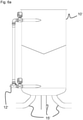
- FIG 1 shows an embodiment of a stirred tank 10 according to the invention as a mixing tank for water treatment.
- a removal device 20 is inserted, preferably welded, into the stirred tank 10 .
- the removal device 20 penetrates the wall of the stirred tank 10.
- water enriched with agglomerates is discharged laterally out of the stirred tank 10 through the removal device, wherein in figure 1 no water and no agglomerates are shown.
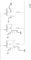
- Only figure 4 schematically shows a snapshot in the method according to the first exemplary embodiment “stirred tank” according to FIG Figures 1 to 3 with fill levels of three stirred tanks for coordinated use in front of a common sieve unit 30 (only in figure 3 shown).
- water treatment system 40 for removing microplastics from water 12 to be cleaned, has three almost continuously acting as essential separating units discontinuously working stirred tank 10 on.
- the three containers placed side by side in a slightly offset manner are preferably those according to figure 1 .
- concentrated agglomerates are separated by means of a removal device 20 in a whirlpool.
- FIGS figures 1 and 2 The exemplary embodiment of such a stirred tank 10 with an advantageously designed removal device 20, which also does not limit the invention, is described in FIGS figures 1 and 2 shown.
- the removal device 20 is horizontally aligned and inserted radially centrally at the top into the stirred tank 10 and breaks through the tank wall on one side. A central overflow is radially routed outwards in a sealed manner with a gradient, without the need for a pump.
- the flow separation tank is also called a rotary tank, but both of these actually also apply to the stirred tank.
- the formation of a vortex as the center of a rotating flow is a prerequisite for separation, as is already known from the prior art.
- the vortex formation is possible in all container variants shown.
- an arm 16S is arranged inside.
- the 16S arm and the tangential inflow together ensure that all particles migrate in the direction of the center of the disc, which is particularly reliable.
- baffle plates 16L are also at the top of the stirred tank 10, 10', below the removal device 20, as part of the removal device 20,.
- the baffles cause the agglomerates to rise as completely as possible up to the rollover edge with or without teeth 26, 26', 26" arranged in the removal device 20, 20', 20".
- an aeration unit 18 distributed over the radius doses fine air bubbles to support the central upflow.
- the agglomeration in the Trombe is additionally optimized in an advantageous embodiment that the outside of the rotating outflow in Little or no air flows against the container.
- An upflowing, rotating vortex with collected microplastic agglomerates is reliably formed radially on the inside.
- a barrier level or zone can be formed in the container by means of air metering. Mixing of process water to be cleaned or even Tromben water with the cleaned water that collects or is to be drawn off in the bottom of the tank is reliably prevented.
- a particularly preferred embodiment has a dosing device (not shown) which is arranged above the liquid level in the container 10, 10', preferably in a container lid. It has an at least roughly radially displaceable dosing end, preferably a dosing end arranged on a pivoting telescopic rod.
- One or more dosing opening(s) distribute additives, in particular hybrid silica gel material, over a certain length of the upflow gap 23 into the trombone water, in which preferably concentrated microplastic particles are whirled onto a funnel-shaped, turbulent liquid surface and there preferably come into contact with a type of hybrid silica material film.
- the preferably used dosing rod integrated into the removal device is retracted radially over a dosing period at least once in a clarification cycle outflowing hybrid silica material and retracted again (parked position flush with the container wall).
- the invention should not be restricted to these types of dosing.
- a subsequent upflow not disturbing integration of the dosing device in the removal device for dosing in the upflow gap when the Liquid level in the container is still in the range 1/3 to 3/4 of the container height is an alternative advantageous embodiment, in this case not mobile but permanently installed. This is an advantageous embodiment that is not shown in the figures.
- the advantage is the improved efficiency of the excipient (additional substance).
- the dosing device doses in between, for example in dosing sequences, during the growth of the thrombus.
- the removal device 20 there are two channels 28R with channel bottoms 28B sloping towards the perforated container side wall 25 at an angle of preferably 1° to 3°, particularly preferably 1.2° with respect to the horizontal.
- An upflow gap 23S runs between the grooves 28R.
- the channel side walls of the channels 28R facing one another are each toothed 26, 26', 26" and/or jagged at the top.
- the rollover edges on the side of the upflow gap are therefore provided with a special geometry, so that the agglomerates can reach the drainage channels 28R, 28R" and flow off with particularly few flow disturbances.
- Figures 8A to 8C not to be understood fundamentally differently.
- the rollover edges of preferred straight embodiments are designed to be adjustable, influencing the flow, in order to be able to be adjusted in the respective application.
- Certain geometries have proven to be advantageous for certain shapes of the agglomerates, in particular the toothed shape of an embodiment discussed in more detail here with toothing that can be displaced in the separating device.
- sinusoidal edge characteristics that are uniformly shaped as exchange edges. So also wave patterns with different wave heights (not shown).
- a jagged shape was also advantageously used (not shown).
- the agglomerate water 21 overflowing in the removal devices 20, 20', 20'' is fed to a single, central screening unit 30.
- a preferred removal device 20 has guide plates 22 inside the channels 28R, cf. figure 5 .
- the baffles 22 extend laterally apart along the upflow gap between the grooves 28R from above looking down into the upflow gap. The trumpet is thus received by the extractor 20 and guided smoothly across the width of the container along the chutes 28R.
- the guide plates 22 and the inner channel walls of each channel 28R preferably form a homogeneous upflow gap, following a straight line and merging into one another without a flow separation edge.
- An upflow gap formed in this way is more than just a side drain. It performs a transformation of movement with flow guidance from the rotation upwards into the overflow and then running off by itself through the channel to the side out of the container.
- the removal device 20 arranged roughly horizontally at the top of the stirred tank 10 functions purely mechanically and without a drive.
- the toothing 26, 26', 26" already mentioned above runs downwards in the respective channel 29R with a non-toothed side wall opposite, with the outer, non-toothed side wall of the channel 28R having a slightly higher upper edge over which no process water /Trombenement overflows from the outside into the channel 28 R.
- the channel 29 R formed in between has the one-sided to the side wall of the Stirring vessel 10 towards sloping channel bottom 29B.
- the channel 29R is therefore designed to fall towards a lateral agglomerate outlet 24 .
- the channel 29R and thus the removal device 20 penetrates the side wall 25 of the stirred tank 10 in its upper tank area.
- the two parallel channels 29R open into a collection trough 29 with the agglomerate outlet 24, so that no pump is required but at least almost no agglomerates are collected in dead spaces and contribute to the blockage of the removal device 20. This enables the microplastic agglomerates collected in the trombe to be transported sideways from the agitated container 10 to the screening unit 30 without any problems.
- the toothings 26 are arranged facing one another on the inside in order to allow an upflowing vortex flow to overflow in a particularly high agglomerate concentration without having to actively skim off.
- the arrangement succeeds in redirecting the circular flow movement into a linear upflow movement.
- Advantageous upflow gap widths 29 are about 25% to 40% of the diameter of the stirred tank.
- the removal device is formed as a cover (not shown) that is completely flat and horizontally closed downwards except for the upflow gap.
- a method according to the invention proceeds as follows: Water to be cleaned is fed tangentially into the stirred tank 10 from the inlet 12 at the top and thus supports the circular liquid movement, which is later intensified by the stirrer 16R, preferably at 300 to 700 revolutions per minute in a stirred tank 10 that is about 150 cm high and has a diameter of 100 cm.
- a particularly preferred interconnection of the stirred tanks in the here specifically as an embodiment figure 3 The proposed container arrangement looks like a continuously operated water treatment plant 40 in the process result, although none of the three stirred tanks 10 in the container works continuously.
- the three stirred tanks 10 in the container are connected in such a way that an at least approximately continuous inflow of water 12 to be cleaned is taken from the outside and an at least largely continuous clear water outflow 38, 11 is provided to the outside.
- a collecting arm 16S which is mounted in the upper tank area.
- the collecting arm 16S and a tangential inflow in the upper container area have the particularly advantageous effect that all particles migrate in the direction of the center of the disc, in a particularly effective localization process.
- aeration is running permanently, since at least temporarily water is permanently introduced into the reactor and the aeration in the water supply line is dependent on the flow rate. All particles, regardless of their density, collect in the trombe, where the fixation process succeeds.
- the inorganic-organic hybrid silicic acid material is repeatedly added to this.
- Solids collected at the end of the process in the stirred tank 20 after removal on the sieve unit 30 are used, for example, as additives in the construction industry.
- the screen unit 30 is designed, for example, as a perforated plate or as a sand filter that can be backwashed.
- Preferred perforated plate widths are in the range from 0.1 to 2.5 mm.
- water to be cleaned is mostly introduced at the bottom, preferably 10% at the bottom and 90% at the top, tangentially into the flow separating tank 10' from the inlet 12 and thus causes the liquid movement, which in this exemplary embodiment is no longer reinforced by a stirrer, preferably with 150 to 500 revolutions per minute in an approximately 2 m high container 10' with a diameter of 100 cm.
- a continuous mode of operation without a stirrer is implemented here, also in accordance with the idea of the invention.
- a continuous mode of operation can be implemented, with decentralized cleaned water being drawn off continuously at the bottom.
- the drum is built up in the center of the container and the introduced rotating liquid to be cleaned rises in the level until it is knocked off at the top at a specific point in time by means of the removal device 20, 20'.
- a camera (not shown) above the reactor regardless of whether it is a stirred vessel 10 or a rotary separator vessel 10′, can look into the upflow gap in an advantageously particularly highly automated exemplary embodiment of this method, preferably an additional sensor that can be taught. In this way, it is observed without manual intervention when at least almost all agglomerates have overflowed. However, this type of monitoring preferably observes beforehand how many agglomerates or how densely agglomerates are collected in the trombe. A regulation according to the invention with its signals is now able to decide when it is worth damming up to use the removal device 20, 20'.
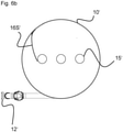
- drains 15' are provided below in order to be able to continuously withdraw purified water.
- a central outlet 15' instead of one otherwise according to the first exemplary embodiment ( figure 1 )
- This access-blocking stirrer has been possible in large proportions, preferably 80% with the distribution of the other 20% to laterally adjacent outlets 15 ', depending on the throughput in continuous operation.
- the vortex or its cup-shaped whirlpool neck is to be stretched to about 1/3 to 2/3 of the height of the container.
- trouble-free operation is achieved simply by controlling the outflow flow rates at the bottom in a central/decentralized split and the inflow flow rates in a top/bottom split.
- the above-mentioned ability to be automated by means of camera and/or sensor monitoring is preferably implemented by pointing at the water surface in order to detect obstructions or foam formation that could render metering of the hybrid silicic acid material ineffective.
- the monitoring means are preferably also used to determine the maturity of the trumpet. If a sufficient number of localization and fixation processes have taken place, it is worthwhile an "exhalation", i.e. an upward flow through the removal direction into the overflow in the direction of the sieve unit.
- Particularly preferred automation means function in the manner of polarization glasses in order to “see” deeper into the Tromb water to avoid reflections on water surfaces.
- a further advantageous embodiment within the scope of the invention uses a further screening unit or the screening unit already provided at the end of the process at the beginning of the treatment process.
- the screen unit is switched into the filling line with water to be cleaned at the beginning of the treatment method in order to prevent coarse particles from entering the reactor, which could reduce the efficiency of the additive.
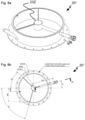
- the third embodiment "Aufströmzirkel 23Z" of a sampling device according to the invention Figures 8A to 8C also works without a pump with a rollover edge and a drain channel with a sloping channel bottom 28R".
- the edge over which the overflowing agglomerates are knocked off in this example is not designed straight across the filling level area, but as a channel entry in a protected circle.
- the in Figure 8A/8B The radius of the upflow ring is approximately the same as that of the Trombe in order to "catch” and enclose the Trombe that is flowing upwards.
- the ring which is open towards the channel, is designed without a top or bottom.
- This removal device 20" also serves to guide the flow.
- the already described container flow upwards on the inside and down the sides causes a tendency on the liquid surface in the mixing container 10, 10' to pull the agglomerates radially outwards.
- the ring has a separating effect on this tendency and the slope of the channel is also sufficient here to allow the agglomerates forced into the channel to run off or, as it were, to pull them off. It is possible to play with the water pressure to increase the force by means of the central ring, because it has a certain height and the channel, in this case as a radial tube (cf. top view in Figure 8B ) designed with an outward slope, see sectional view in Figure 8C , in or slightly below the liquid level in the container 10, 10".
- the ring is widened downwards in a funnel shape (not shown).
- the channel is flattened towards the ring, so that a wide overflow edge receives the agglomerates.
Landscapes
- Chemical & Material Sciences (AREA)
- Life Sciences & Earth Sciences (AREA)
- Engineering & Computer Science (AREA)
- Organic Chemistry (AREA)
- Biotechnology (AREA)
- Chemical Kinetics & Catalysis (AREA)
- Hydrology & Water Resources (AREA)
- Environmental & Geological Engineering (AREA)
- Water Supply & Treatment (AREA)
- Mixers Of The Rotary Stirring Type (AREA)
- Physical Water Treatments (AREA)
- Removal Of Specific Substances (AREA)
Applications Claiming Priority (1)
| Application Number | Priority Date | Filing Date | Title |
|---|---|---|---|
| DE102020004662.2A DE102020004662B4 (de) | 2020-07-31 | 2020-07-31 | Wasseraufbereitungsverfahren zur Entfernung von Schadstoffen sowie Wasseraufbereitungsanlage hierfür |
Publications (2)
| Publication Number | Publication Date |
|---|---|
| EP3945071A2 true EP3945071A2 (fr) | 2022-02-02 |
| EP3945071A3 EP3945071A3 (fr) | 2022-04-13 |
Family
ID=77179844
Family Applications (1)
| Application Number | Title | Priority Date | Filing Date |
|---|---|---|---|
| EP21020394.9A Withdrawn EP3945071A3 (fr) | 2020-07-31 | 2021-08-02 | Procédé de traitement des eaux destiné à l'élimination des polluants, installation de traitement des eaux correspondante, ainsi qu'élément rapporté de distribution |
Country Status (2)
| Country | Link |
|---|---|
| EP (1) | EP3945071A3 (fr) |
| DE (1) | DE102020004662B4 (fr) |
Cited By (2)
| Publication number | Priority date | Publication date | Assignee | Title |
|---|---|---|---|---|
| CN115178005A (zh) * | 2022-09-13 | 2022-10-14 | 冠森新材料(烟台)有限公司 | 一种聚酯树脂循环过滤生产装置 |
| EP4644332A1 (fr) * | 2024-05-03 | 2025-11-05 | Zahnen Technik GmbH | Agent d'agglomération pour lier des particules de microplastiques et/ou des polluants dans l'eau, procédé de production d'agent d'agglomération, dispositif de traitement d'eau et procédé de traitement d'eau |
Citations (3)
| Publication number | Priority date | Publication date | Assignee | Title |
|---|---|---|---|---|
| US4626345A (en) * | 1984-09-04 | 1986-12-02 | Lenox Institute For Research, Inc. | Apparatus for clarification of water |
| US5192423A (en) * | 1992-01-06 | 1993-03-09 | Hydro Processing & Mining Ltd. | Apparatus and method for separation of wet particles |
| WO2019219106A1 (fr) | 2018-05-14 | 2019-11-21 | Zahnen Technik Gmbh | Procédé et système de traitement de l'eau, notamment pour l'élimination de la pollution anthropogénique sous la forme de micro-matière synthétique et/ou micro-substances nocives organo-chimiques dissoutes |
Family Cites Families (3)
| Publication number | Priority date | Publication date | Assignee | Title |
|---|---|---|---|---|
| FR2930539A1 (fr) * | 2008-04-25 | 2009-10-30 | Anjou Rech | Procede de traitement de fluide par hydrocylone |
| DE102015207061A1 (de) | 2015-04-17 | 2016-10-20 | Universität Koblenz-Landau | Hybridkieselsäurematerial, insbesondere zur Fixierung anthropogener Verunreinigungen aus einem aquatischen Umfeld |
| DE102015211052A1 (de) | 2015-06-16 | 2016-12-22 | Universität Koblenz-Landau | Hybridkieselsäurematerial, insbesondere zur Fixierung anthropogener Verunreinigungen aus einem aquatischen Umfeld |
-
2020
- 2020-07-31 DE DE102020004662.2A patent/DE102020004662B4/de active Active
-
2021
- 2021-08-02 EP EP21020394.9A patent/EP3945071A3/fr not_active Withdrawn
Patent Citations (3)
| Publication number | Priority date | Publication date | Assignee | Title |
|---|---|---|---|---|
| US4626345A (en) * | 1984-09-04 | 1986-12-02 | Lenox Institute For Research, Inc. | Apparatus for clarification of water |
| US5192423A (en) * | 1992-01-06 | 1993-03-09 | Hydro Processing & Mining Ltd. | Apparatus and method for separation of wet particles |
| WO2019219106A1 (fr) | 2018-05-14 | 2019-11-21 | Zahnen Technik Gmbh | Procédé et système de traitement de l'eau, notamment pour l'élimination de la pollution anthropogénique sous la forme de micro-matière synthétique et/ou micro-substances nocives organo-chimiques dissoutes |
Cited By (2)
| Publication number | Priority date | Publication date | Assignee | Title |
|---|---|---|---|---|
| CN115178005A (zh) * | 2022-09-13 | 2022-10-14 | 冠森新材料(烟台)有限公司 | 一种聚酯树脂循环过滤生产装置 |
| EP4644332A1 (fr) * | 2024-05-03 | 2025-11-05 | Zahnen Technik GmbH | Agent d'agglomération pour lier des particules de microplastiques et/ou des polluants dans l'eau, procédé de production d'agent d'agglomération, dispositif de traitement d'eau et procédé de traitement d'eau |
Also Published As
| Publication number | Publication date |
|---|---|
| DE102020004662B4 (de) | 2022-08-11 |
| DE102020004662A1 (de) | 2022-02-03 |
| EP3945071A3 (fr) | 2022-04-13 |
Similar Documents
| Publication | Publication Date | Title |
|---|---|---|
| DE7138603U (de) | Vorrichtung zur mechanisch-chemischen Wasseraufbereitung und Abwasserbehandlung | |
| EP3945071A2 (fr) | Procédé de traitement des eaux destiné à l'élimination des polluants, installation de traitement des eaux correspondante, ainsi qu'élément rapporté de distribution | |
| DE69900253T2 (de) | Vorrichtung zur Klärung einer durch Flotation beladenen Flüssigkeit | |
| EP0412173A1 (fr) | Procédé et installation de traitement et de purification de l'eau usée | |
| DE3409107A1 (de) | Verfahren und vorrichtung zur trennung der feststoffe von der traegerfluessigkeit bei suspensionen sowie dafuer geeignete zentrifuge | |
| AT511542B1 (de) | Vorrichtung zur abtrennung von gasen aus einer suspension | |
| EP0564935A1 (fr) | Station d'épuration d'eaux usées | |
| EP1854524B1 (fr) | Installation de traitement d'eaux usées avec séparation de boues activées améliorée | |
| CH384485A (de) | Verfahren und Vorrichtung zur Klärung von Flüssigkeiten, insbesondere Abwasser | |
| DE4407343C2 (de) | Vorrichtung zum Abscheiden von Partikeln mit fester Konsistenz aus einer Flüssigkeit | |
| DE1517551C3 (de) | Wasseraufbereitungs- oder Abwasserbehandlungsanlage | |
| DE2806109A1 (de) | Vorrichtung zum reinigen von fluessigkeiten | |
| DE19850320C2 (de) | Kompaktanlage für die mechanische Reinigung von Abwasser | |
| AT517984B1 (de) | Trennbehälter | |
| EP2627426B1 (fr) | Dispositif pour séparer des substances en suspension | |
| EP0264900A2 (fr) | Etape de prédéshydratation de boues et de produits similaires | |
| DE3943416C2 (de) | Verfahren zum Entwässern von stark wasserhaltigen Suspensionen wie Gülle, Abwässern und dünnflüssigen Schlämmen sowie entsprechende Vorrichtung | |
| DE2104861B2 (de) | Verfahren und Vorrichtung zur kontinuierlichen Filtration von Flüssigkeiten | |
| DE102006020273B4 (de) | Vorrichtung und Verfahren zum Reinigen von Abwasser | |
| EP0621076B1 (fr) | Procédé pour la séparation de solides | |
| DE4429537C2 (de) | Abwasserreinigungsanlage | |
| EP0951326B1 (fr) | Bassin de decantation de forme rectangulaire pour la separation de la boue contenue dans des eaux usees | |
| DE69124240T2 (de) | Abschneider | |
| DE2740645A1 (de) | Rundraeumer zur abwasserklaerung | |
| DE2349218B1 (de) | Klaeranlage zum biologischen Reinigen von Abwasser |
Legal Events
| Date | Code | Title | Description |
|---|---|---|---|
| PUAI | Public reference made under article 153(3) epc to a published international application that has entered the european phase |
Free format text: ORIGINAL CODE: 0009012 |
|
| STAA | Information on the status of an ep patent application or granted ep patent |
Free format text: STATUS: THE APPLICATION HAS BEEN PUBLISHED |
|
| AK | Designated contracting states |
Kind code of ref document: A2 Designated state(s): AL AT BE BG CH CY CZ DE DK EE ES FI FR GB GR HR HU IE IS IT LI LT LU LV MC MK MT NL NO PL PT RO RS SE SI SK SM TR |
|
| PUAL | Search report despatched |
Free format text: ORIGINAL CODE: 0009013 |
|
| AK | Designated contracting states |
Kind code of ref document: A3 Designated state(s): AL AT BE BG CH CY CZ DE DK EE ES FI FR GB GR HR HU IE IS IT LI LT LU LV MC MK MT NL NO PL PT RO RS SE SI SK SM TR |
|
| RIC1 | Information provided on ipc code assigned before grant |
Ipc: B03D 1/14 20060101ALI20220309BHEP Ipc: B01J 4/02 20060101ALI20220309BHEP Ipc: C02F 1/28 20060101ALI20220309BHEP Ipc: C02F 1/54 20060101ALI20220309BHEP Ipc: C02F 1/24 20060101AFI20220309BHEP |
|
| STAA | Information on the status of an ep patent application or granted ep patent |
Free format text: STATUS: REQUEST FOR EXAMINATION WAS MADE |
|
| 17P | Request for examination filed |
Effective date: 20221013 |
|
| RBV | Designated contracting states (corrected) |
Designated state(s): AL AT BE BG CH CY CZ DE DK EE ES FI FR GB GR HR HU IE IS IT LI LT LU LV MC MK MT NL NO PL PT RO RS SE SI SK SM TR |
|
| STAA | Information on the status of an ep patent application or granted ep patent |
Free format text: STATUS: EXAMINATION IS IN PROGRESS |
|
| 17Q | First examination report despatched |
Effective date: 20250122 |
|
| STAA | Information on the status of an ep patent application or granted ep patent |
Free format text: STATUS: THE APPLICATION HAS BEEN WITHDRAWN |
|
| 18W | Application withdrawn |
Effective date: 20250317 |