EP3946775B1 - Dispositif pour l'équipement d'une machine à souder les paniers et machine à souder les paniers - Google Patents
Dispositif pour l'équipement d'une machine à souder les paniers et machine à souder les paniers Download PDFInfo
- Publication number
- EP3946775B1 EP3946775B1 EP19716867.7A EP19716867A EP3946775B1 EP 3946775 B1 EP3946775 B1 EP 3946775B1 EP 19716867 A EP19716867 A EP 19716867A EP 3946775 B1 EP3946775 B1 EP 3946775B1
- Authority
- EP
- European Patent Office
- Prior art keywords
- insertion device
- receiving
- welding machine
- receiving element
- axis
- Prior art date
- Legal status (The legal status is an assumption and is not a legal conclusion. Google has not performed a legal analysis and makes no representation as to the accuracy of the status listed.)
- Active
Links
Images



Classifications
-
- B—PERFORMING OPERATIONS; TRANSPORTING
- B21—MECHANICAL METAL-WORKING WITHOUT ESSENTIALLY REMOVING MATERIAL; PUNCHING METAL
- B21F—WORKING OR PROCESSING OF METAL WIRE
- B21F27/00—Making wire network, i.e. wire nets
- B21F27/12—Making special types or portions of network by methods or means specially adapted therefor
- B21F27/121—Making special types or portions of network by methods or means specially adapted therefor of tubular form, e.g. as reinforcements for pipes or pillars
-
- B—PERFORMING OPERATIONS; TRANSPORTING
- B23—MACHINE TOOLS; METAL-WORKING NOT OTHERWISE PROVIDED FOR
- B23K—SOLDERING OR UNSOLDERING; WELDING; CLADDING OR PLATING BY SOLDERING OR WELDING; CUTTING BY APPLYING HEAT LOCALLY, e.g. FLAME CUTTING; WORKING BY LASER BEAM
- B23K9/00—Arc welding or cutting
- B23K9/12—Automatic feeding or moving of electrodes or work for spot or seam welding or cutting
- B23K9/133—Means for feeding electrodes, e.g. drums, rolls, motors
-
- B—PERFORMING OPERATIONS; TRANSPORTING
- B23—MACHINE TOOLS; METAL-WORKING NOT OTHERWISE PROVIDED FOR
- B23K—SOLDERING OR UNSOLDERING; WELDING; CLADDING OR PLATING BY SOLDERING OR WELDING; CUTTING BY APPLYING HEAT LOCALLY, e.g. FLAME CUTTING; WORKING BY LASER BEAM
- B23K37/00—Auxiliary devices or processes, not specially adapted for a procedure covered by only one of the other main groups of this subclass
- B23K37/04—Auxiliary devices or processes, not specially adapted for a procedure covered by only one of the other main groups of this subclass for holding or positioning work
- B23K37/0426—Fixtures for other work
-
- B—PERFORMING OPERATIONS; TRANSPORTING
- B21—MECHANICAL METAL-WORKING WITHOUT ESSENTIALLY REMOVING MATERIAL; PUNCHING METAL
- B21F—WORKING OR PROCESSING OF METAL WIRE
- B21F23/00—Feeding wire in wire-working machines or apparatus
- B21F23/005—Feeding discrete lengths of wire or rod
-
- B—PERFORMING OPERATIONS; TRANSPORTING
- B21—MECHANICAL METAL-WORKING WITHOUT ESSENTIALLY REMOVING MATERIAL; PUNCHING METAL
- B21F—WORKING OR PROCESSING OF METAL WIRE
- B21F27/00—Making wire network, i.e. wire nets
- B21F27/12—Making special types or portions of network by methods or means specially adapted therefor
- B21F27/121—Making special types or portions of network by methods or means specially adapted therefor of tubular form, e.g. as reinforcements for pipes or pillars
- B21F27/122—Making special types or portions of network by methods or means specially adapted therefor of tubular form, e.g. as reinforcements for pipes or pillars by attaching a continuous stirrup to longitudinal wires
- B21F27/124—Making special types or portions of network by methods or means specially adapted therefor of tubular form, e.g. as reinforcements for pipes or pillars by attaching a continuous stirrup to longitudinal wires applied by rotation
-
- B—PERFORMING OPERATIONS; TRANSPORTING
- B23—MACHINE TOOLS; METAL-WORKING NOT OTHERWISE PROVIDED FOR
- B23K—SOLDERING OR UNSOLDERING; WELDING; CLADDING OR PLATING BY SOLDERING OR WELDING; CUTTING BY APPLYING HEAT LOCALLY, e.g. FLAME CUTTING; WORKING BY LASER BEAM
- B23K37/00—Auxiliary devices or processes, not specially adapted for a procedure covered by only one of the other main groups of this subclass
-
- B—PERFORMING OPERATIONS; TRANSPORTING
- B65—CONVEYING; PACKING; STORING; HANDLING THIN OR FILAMENTARY MATERIAL
- B65G—TRANSPORT OR STORAGE DEVICES, e.g. CONVEYORS FOR LOADING OR TIPPING, SHOP CONVEYOR SYSTEMS OR PNEUMATIC TUBE CONVEYORS
- B65G29/00—Rotary conveyors, e.g. rotating discs, arms, star-wheels or cones
-
- B—PERFORMING OPERATIONS; TRANSPORTING
- B65—CONVEYING; PACKING; STORING; HANDLING THIN OR FILAMENTARY MATERIAL
- B65G—TRANSPORT OR STORAGE DEVICES, e.g. CONVEYORS FOR LOADING OR TIPPING, SHOP CONVEYOR SYSTEMS OR PNEUMATIC TUBE CONVEYORS
- B65G47/00—Article or material-handling devices associated with conveyors; Methods employing such devices
- B65G47/74—Feeding, transfer, or discharging devices of particular kinds or types
- B65G47/84—Star-shaped wheels or devices having endless travelling belts or chains, the wheels or devices being equipped with article-engaging elements
-
- B—PERFORMING OPERATIONS; TRANSPORTING
- B21—MECHANICAL METAL-WORKING WITHOUT ESSENTIALLY REMOVING MATERIAL; PUNCHING METAL
- B21F—WORKING OR PROCESSING OF METAL WIRE
- B21F27/00—Making wire network, i.e. wire nets
- B21F27/12—Making special types or portions of network by methods or means specially adapted therefor
- B21F27/121—Making special types or portions of network by methods or means specially adapted therefor of tubular form, e.g. as reinforcements for pipes or pillars
- B21F27/122—Making special types or portions of network by methods or means specially adapted therefor of tubular form, e.g. as reinforcements for pipes or pillars by attaching a continuous stirrup to longitudinal wires
-
- B—PERFORMING OPERATIONS; TRANSPORTING
- B23—MACHINE TOOLS; METAL-WORKING NOT OTHERWISE PROVIDED FOR
- B23K—SOLDERING OR UNSOLDERING; WELDING; CLADDING OR PLATING BY SOLDERING OR WELDING; CUTTING BY APPLYING HEAT LOCALLY, e.g. FLAME CUTTING; WORKING BY LASER BEAM
- B23K2101/00—Articles made by soldering, welding or cutting
- B23K2101/04—Tubular or hollow articles
- B23K2101/06—Tubes
-
- B—PERFORMING OPERATIONS; TRANSPORTING
- B23—MACHINE TOOLS; METAL-WORKING NOT OTHERWISE PROVIDED FOR
- B23K—SOLDERING OR UNSOLDERING; WELDING; CLADDING OR PLATING BY SOLDERING OR WELDING; CUTTING BY APPLYING HEAT LOCALLY, e.g. FLAME CUTTING; WORKING BY LASER BEAM
- B23K2103/00—Materials to be soldered, welded or cut
- B23K2103/02—Iron or ferrous alloys
- B23K2103/04—Steel or steel alloys
-
- B—PERFORMING OPERATIONS; TRANSPORTING
- B65—CONVEYING; PACKING; STORING; HANDLING THIN OR FILAMENTARY MATERIAL
- B65G—TRANSPORT OR STORAGE DEVICES, e.g. CONVEYORS FOR LOADING OR TIPPING, SHOP CONVEYOR SYSTEMS OR PNEUMATIC TUBE CONVEYORS
- B65G47/00—Article or material-handling devices associated with conveyors; Methods employing such devices
- B65G47/02—Devices for feeding articles or materials to conveyors
- B65G47/04—Devices for feeding articles or materials to conveyors for feeding articles
- B65G47/12—Devices for feeding articles or materials to conveyors for feeding articles from disorderly-arranged article piles or from loose assemblages of articles
- B65G47/14—Devices for feeding articles or materials to conveyors for feeding articles from disorderly-arranged article piles or from loose assemblages of articles arranging or orientating the articles by mechanical or pneumatic means during feeding
- B65G47/1407—Devices for feeding articles or materials to conveyors for feeding articles from disorderly-arranged article piles or from loose assemblages of articles arranging or orientating the articles by mechanical or pneumatic means during feeding the articles being fed from a container, e.g. a bowl
Definitions
- a device for equipping a basket welding machine is already available from the JP H02 15843 A known.
- a known loading device is designed as an automated device which loads a cage welding machine with longitudinal wires of a reinforcement cage to be produced, wherein the device feeds the longitudinal wires of the reinforcement cage to be produced individually, one after the other in the direction of a longitudinal axis of the cage welding machine, wherein the longitudinal axis corresponds to a rotation axis of the cage welding machine.
- the device and the cage welding machine are coordinated in such a way that a production wheel of the cage welding machine, after a single receiving position has been equipped with a single longitudinal wire by the device, rotates further around a rotation axis of the production wheel by one receiving position, so that another receiving position of the production wheel, which is not yet equipped with a longitudinal wire, can be equipped by the device.
- the process is repeated until the cage welding machine is equipped with all the longitudinal wires required for the production of a reinforcement cage by the device.
- the invention is based on the object of providing an improved device for equipping a basket welding machine, in particular to provide an improved device for equipping a basket welding machine, by means of which a comparatively faster equipping of the basket welding machine can be realized.
- the invention is based on a device for equipping a basket welding machine, wherein the device has a push-in device.
- the device is designed as a push-in device for feeding longitudinal wires to a basket welding machine.
- the basket is designed, for example, as a reinforcement basket.
- the basket welding machine is advantageously designed for producing reinforcements, in particular for producing reinforcement baskets for concrete pipes.
- the basket welding machine comprises a welding system for welding a longitudinal wire to a cross wire and/or a binding unit for connecting the longitudinal wire to the cross wire, for example by means of a loop.
- the basket welding machine advantageously comprises a spreading device which has a spreading slide, wherein the spreading slide is designed to change a radial position of an adjusting element for a longitudinal wire of the reinforcement via a transmission means of the spreading device, in particular during the manufacturing process of the reinforcement.
- the adjusting element is advantageously present on a spreading wheel of the basket welding machine.
- the transmission means of the spreading device are, for example, designed as a drive chain and/or as a Drive rod formed.
- the spreading wheel for example a main wheel and/or a feed wheel, comprises e.g. 4 to 48 spokes, 8 to 40 spokes, 12 to 36 spokes, 16 to 32 spokes or 20 to 28 spokes, in particular 24 spokes.
- the basket welding machine preferably comprises a main wheel and a feed wheel.
- the main wheel is present, for example, as a spreading wheel.
- Wire guide tubes are advantageously attached to the main wheel, in particular to the spokes of the main wheel.
- the wire guide tubes are preferably provided on the main wheel so that they can move in the radial direction.
- the feed wheel is advantageously designed to clamp the longitudinal wires and to transport the longitudinal wires along a rotation axis of the basket welding machine away from the main wheel during production of the basket.
- the cage e.g. in the form of a reinforcement body or a reinforcement cage, is advantageously designed as a reinforcement of a pipe, a pile, a support and/or a pillar.
- the reinforcement body is designed, for example, in a cross-section, in particular transverse to a longitudinal extension of a rod, to be rectangular, square, polygonal or polygonal, round and/or oval.
- the cage e.g. the reinforcement body
- the cage has a plurality of longitudinal wires and a wire, in particular a winding wire, wherein the longitudinal wires can be connected to the winding wire by the cage welding machine. It is also conceivable that two, three or more winding wires are provided on the reinforcement body.
- a longitudinal wire is advantageously designed in the form of a rod.
- a longitudinal wire is present, for example, as a rod, in particular as a longitudinal rod.
- the cage welding machine is, for example, a pile reinforcement cage welding machine and/or a pillar reinforcement cage welding machine and/or as a pipe reinforcement cage welding machine and/or as a reinforcement pipe welding machine. It is also conceivable that a reinforcement mesh cage, e.g. a 3-dimensional reinforcement mesh, can be produced with the proposed cage welding machine.
- the insertion device has a receiving element for receiving longitudinal wires of a basket to be produced with the basket welding machine, wherein the insertion device has a plurality of receiving positions for all longitudinal wires of the basket on the receiving element, wherein the receiving positions are spaced apart in the radial direction from a rotation axis of the insertion device, wherein the insertion device is designed to feed at least two longitudinal wires arranged on the insertion device to the basket welding machine simultaneously in an insertion process, wherein the insertion process of the longitudinal wires to the basket welding machine takes place by a movement of the insertion device in the axial direction of the rotation axis of the insertion device, wherein two receiving elements are present, wherein the receiving elements comprise the receiving positions, wherein the two receiving elements are displaceable in an axial direction to the rotation axis D of the insertion device.
- the basket welding machine can be equipped with longitudinal wires comparatively quickly.
- the insertion device is designed to simultaneously feed at least 3, 4, 5, 6, 7, 8, 9, 10, 11, 12, 14, 16 or at least 18 longitudinal wires arranged on the insertion device to the basket welding machine in one insertion process.
- the insertion device is designed, for example, as a longitudinal wire feeding device.
- the axial direction of the rotation axis is understood to mean a direction along the rotation axis of the insertion device.
- the axial direction of the rotation axis is understood to mean a Direction along and/or parallel to a longitudinal extension of the rotation axis of the insertion device.
- a radial direction of the rotation axis is understood to mean a direction transverse to the axial direction of the rotation axis.
- a radial direction of the rotation axis is understood to mean a direction transverse to the longitudinal extension of the rotation axis of the insertion device towards the rotation axis or away from the rotation axis.
- the receiving element is advantageously designed as a loading wheel.
- the receiving element in particular in the form of the loading wheel, is advantageously movable, e.g. rotatable, about the rotation axis of the insertion device.
- the assembly wheel comprises, for example, 4 to 48 spokes, 8 to 40 spokes, 12 to 36 spokes, 16 to 32 spokes or 20 to 28 spokes, in particular 24 spokes.
- the assembly wheel comprises, for example, 4, 6, 8, 10, 12, 14, 16, 28, 32, 36, 40, 48 or more spokes.
- the receiving element comprises more than two receiving positions, in particular more than 4 receiving positions.
- the receiving element comprises 4, 6, 8, 10, 12, 14, 16, 18, 20, 22, 24, 26, 28, 30, 32, 36, 40 or 48 receiving positions.
- the receiving positions are advantageously formed in the area of the spokes.
- each spoke comprises a receiving position.
- a receiving position is present, for example, as a slot-like recess on the receiving element or the receiving element.
- the recess is designed, for example, as a slot.
- the receiving position is designed, for example, as a slot-like, e.g. U-shaped or V-shaped recess.
- a longitudinal extension of the recess is advantageously designed tangentially to the axis of rotation of the insertion device.
- the slot extends tangentially to the axis of rotation of the insertion device.
- the insertion device is preferably designed to feed the basket welding machine, in particular the spreading device of the basket welding machine, at least two longitudinal wires arranged on the insertion device in a single insertion process and/or to transfer them to the basket welding machine.
- the insertion process advantageously comprises a single movement in an exclusively axial direction of the axis of rotation.
- the movement advantageously takes place along an axis of rotation of the axis of rotation of the insertion device.
- the insertion process comprises a movement that is exclusively parallel to the axis of rotation.
- the insertion device is advantageously designed to feed all the longitudinal wires arranged on the insertion device to the basket welding machine together in a single insertion process. All the longitudinal wires required to produce a basket can preferably be arranged on the insertion device.
- the insertion process preferably takes place by means of a single movement of the insertion device in the axial direction.
- the insertion process comprises several, in particular linear, movements of the insertion device.
- the insertion process comprises several movements of the insertion device, with all movements being parallel to the axis of rotation of the insertion device.
- all movements of the insertion process are aligned parallel to one another.
- the insertion process advantageously takes place by a movement of the receiving element in the direction of the basket welding machine.
- the insertion process comprises several movements of the receiving element, with all movements of the receiving element being parallel to the axis of rotation of the insertion device.
- the insertion process comprises a movement of the receiving element towards the basket welding machine, in particular towards the spreading device of the basket welding machine, and a movement and/or movement back from the basket welding machine, in particular from the Spreading device of the basket welding machine, away.
- the forward movement is to be understood as a forward movement.
- the insertion device in particular the receiving element, can be equipped with all longitudinal wires that are required to produce a basket in a single assembly process.
- the assembly process takes place completely before the insertion process.
- the insertion device is designed to be able to be equipped with the longitudinal wire by moving the longitudinal wire in a direction transverse to the axis of rotation of the insertion device.
- a further advantageous embodiment of the invention is that the device has a feed device, wherein the feed device has a storage rack, a separating device, a transport device and/or a transfer device and is designed to feed longitudinal wires to the insertion device, wherein the insertion device is designed to be equipped with the longitudinal wire by moving the longitudinal wire in a direction transverse to the axis of rotation of the insertion device and the feed device equips the insertion device from the side.
- the insertion device can be equipped with longitudinal wires relatively quickly.
- the insertion device can be equipped with longitudinal wires more quickly by the feed device than a basket welding machine needs to produce the basket.
- the side of the insertion device is advantageously present on the circumference of the insertion device.
- the side of the insertion device can be seen circumferentially outwards.
- the side of the insertion device can be seen transversely to the axis of rotation of the insertion device away from the axis of rotation.
- one of the two receiving elements is designed in the form of a ring disk, wheel-shaped and/or cylindrical and comprises a jacket surface, e.g. a cylinder jacket surface.
- the jacket surface or the cylinder jacket surface forms advantageously the side of the insertion device.
- a receiving element forms a recess on the casing surface.
- the insertion device is designed to be equipped with a longitudinal wire in a lateral direction to the axis of rotation of the insertion device.
- the insertion device is designed to be equipped with longitudinal wires in a radial direction to the axis of rotation of the insertion device.
- the longitudinal wires are mounted on the feed device in such a way that a longitudinal extension of the longitudinal wires is aligned along the axis of rotation, in particular parallel to the axis of rotation.
- the feed device, in particular the transfer device is designed in such a way that the feed device feeds the longitudinal wires to the insertion device in a direction transverse to the longitudinal extension of the longitudinal wires.
- the storage rack of the feed device is advantageously designed such that more longitudinal wires can be stored on or in the storage rack than are required to produce a basket.
- the storage rack is advantageously designed as a container, in particular as a tub.
- the singling device is designed, for example, such that the singling device takes a single longitudinal wire from a supply of longitudinal wires stored in or on the storage frame and/or separates a single longitudinal wire from the supply and feeds it to the transport device.
- the singling device is preferably designed to feed a single longitudinal wire to the transport device.
- the singling device is advantageously designed to feed individual longitudinal wires to the transport device one after the other.
- the transfer device is designed to ensure a transfer of a single longitudinal wire in particular from the transport device to the insertion device.
- the transfer device is advantageously provided as a slide.
- the slide is designed such that a longitudinal wire can be moved in particular exclusively transversely to its longitudinal extension from the transport device in the direction of the insertion device.
- the receiving elements encompass the receiving positions. This means that the longitudinal wires can be stored relatively safely and/or precisely positioned on the insertion device. This also makes it possible to feed the longitudinal wires to the basket welding machine relatively quickly.
- the receiving elements are arranged next to one another along the axis of rotation of the insertion device.
- the receiving elements are arranged one behind the other in the axial direction of the axis of rotation.
- Each receiving element advantageously comprises an axis of rotation.
- the axes of rotation of the two receiving elements extend in the same direction.
- the axes of rotation of the two receiving elements are aligned parallel to one another.
- the axes of rotation of the two receiving elements, in particular of all receiving elements of the insertion device coincide with one another.
- the axes of rotation of the two receiving elements, in particular of all receiving elements of the insertion device form the axis of rotation of the insertion device.
- the axes of rotation of the receiving elements and the axis of rotation of the insertion device coincide with one another.
- the receiving positions are advantageously distributed circumferentially around the axis of rotation of the receiving element, in particular distributed circumferentially around the insertion device rotation axis.
- the receiving elements are spaced apart from one another at a fixed, in particular unchangeable distance.
- the receiving elements are mechanically coupled to one another.
- the receiving elements are spaced apart from one another in the axial direction at a fixed, in particular unchangeable distance.
- the side of the insertion device extends in the axial direction of the axis of rotation of the insertion device from one receiving element to the other receiving element.
- the side of the insertion device extends along the axis of rotation of the insertion device from one receiving element to the other receiving element.
- a first receiving position of a first receiving element and a first receiving position of a second receiving element are aligned with one another in such a way that a longitudinal wire can be arranged in the two first receiving positions, so that when the longitudinal wire is arranged at the first receiving positions, the longitudinal wire has a longitudinal extension along, in particular parallel to, the axis of rotation of the insertion device.
- the first and second receiving elements are arranged with one another in such a way that a receiving position of the first receiving element and a receiving position of the second receiving element are aligned with one another in such a way that all the longitudinal wires required to produce a basket can be arranged in the receiving position, so that when the longitudinal wires are arranged at the receiving positions, the longitudinal wires have a longitudinal extension along, in particular parallel to, the axis of rotation of the insertion device.
- all receiving positions of a receiving element are formed on the receiving element at the same distance in the radial direction from the axis of rotation of the receiving element and/or the axis of rotation of the insertion device.
- all receiving positions of all receiving elements are formed on the receiving elements at the same distance in the radial direction from the axis of rotation of the insertion device.
- all receiving positions on a receiving element are formed in a fixed position on the receiving element.
- all receiving positions on a receiving element are formed in a fixed position on the receiving element in a radial direction of the axis of rotation of the insertion device.
- the two receiving elements are movable along the rotation axis of the insertion device and/or along an extension of the rotation axis of the insertion device.
- each receiving element of the insertion device is movable, in particular is mounted in a movable manner.
- At least one receiving element can be positioned relative to another receiving element.
- the receiving elements can be positioned relative to one another.
- a receiving element can be positioned in the axial direction relative to another receiving element, in particular is displaceable.
- the insertion device has a shaft, wherein the shaft and at least one receiving element are connected to one another in a rotationally fixed manner, so that a rotational movement of the shaft causes a rotational movement of the receiving element.
- positions of the receiving positions can be changed by rotating the shaft about an axis of rotation of the shaft.
- the axis of rotation of the shaft advantageously corresponds to the axis of rotation of the insertion device.
- the shaft is in the form of a guide unit, wherein the guide unit advantageously has a rail-like guide element.
- the guide unit advantageously has a rail-like guide element.
- a receiving element is provided which is guided by the rail-like guide element in the axial direction of the axis of rotation on the shaft.
- the shaft advantageously comprises two rail-like guide elements.
- the rail-like guide element is designed as a guide rail.
- the shaft advantageously comprises a gear unit for driving a receiving element.
- the gear unit is designed, for example, as a chain drive and/or as a toothed belt drive.
- the shaft is advantageously designed such that it can be rotatably mounted on the basket welding machine with one shaft end.
- the shaft is connected to a drive of the insertion device at a second shaft end, the second shaft end being spaced along the axis of rotation and opposite the first shaft end.
- the drive of the insertion device is designed, for example, to drive, in particular to rotate, the shaft.
- a spreading drive for driving the spreading device of the basket welding machine is present at the second shaft end.
- the spreading drive is advantageously coupled to the second shaft end.
- a receiving element has a support element, wherein the receiving element is rotatably mounted on the support element.
- the shaft is supported, in particular mounted, via a first receiving element.
- the support element is designed, for example, as a shell-like receptacle, e.g. as a half-shell.
- the support element comprises a guide by means of which the receiving element is mounted so as to be rotatable about the axis of rotation of the receiving element, in particular about the axis of rotation of the insertion device.
- the support element is advantageously designed as a support foot, in particular with a shell-like receptacle.
- the shell-like receptacle preferably forms the guide for the receiving element.
- the support element is advantageously mounted so that it can move on a guide element.
- the support element is mounted so that it can move along the axis of rotation of the shaft.
- the receiving elements are advantageously mounted so that it can move on a guide element and/or the rail-like guide element.
- all receiving elements are mounted so that they can move on the guide element and/or on the rail-like guide element.
- the guide element is designed, for example, as a rail element, e.g. as a rail.
- the support element advantageously supports the receiving element on a floor surface.
- the insertion device can be set up on the floor surface.
- the support element is advantageously supported on the floor surface via the guide element.
- a second receiving element is provided along the axis of rotation between the first receiving element and the drive of the shaft.
- a receiving element comprises clamping elements, wherein the clamping elements are designed to clamp the longitudinal wires mounted on the receiving element.
- the clamping elements are advantageously present in the region of a receiving position, in particular at the receiving position.
- exactly one clamping element is present at a receiving position.
- two clamping elements are present at each receiving position.
- two clamping elements are designed in a pliers-like manner on the receiving element.
- a clamping element comprises a buffer element, for example two buffer elements.
- a clamping element comprises exactly one buffer element, e.g. exactly two buffer elements.
- the buffer element is, for example, elastic, e.g. buffer-like, in particular flexible. It is conceivable that the buffer element is present as a rubber buffer.
- a longitudinal wire arranged at the receiving position is fixed at the receiving position by the clamping element.
- the clamping element rests against the longitudinal wire, in particular with a stop surface in the closed position.
- the clamping element presses the longitudinal wire against a stop of the receiving position, so that the longitudinal wire is clamped between the stop of the receiving position and the stop surface of the clamping element.
- the insertion device advantageously comprises a drive unit, in particular a pneumatic drive unit, by means of which a movement of the clamping elements can be driven.
- the drive unit advantageously comprises a pneumatic drive.
- the pneumatic drive is designed, for example, as a pneumatic cylinder.
- several drive units e.g. two, three, five or six, in particular four drive units, are arranged on a receiving element.
- several pneumatic drives e.g. several pneumatic cylinders, are arranged on a receiving element.
- two, three, five, six or four pneumatic drives are present on a receiving element.
- the drive unit preferably comprises a buffer storage, which is present on the receiving element.
- a buffer storage By using a buffer storage, the insertion device can be designed comparatively quickly and inexpensively.
- the buffer storage is advantageously mounted so that it can rotate about the axis of rotation of the receiving element, in particular about the axis of rotation of the insertion device.
- the drive unit comprises several buffer storages, in particular two, three or four buffer storages.
- each buffer storage is arranged on a receiving element. It is also conceivable that two, three, four or more buffer storages are arranged on each receiving element.
- the buffer storage is designed as a tank, e.g. as a pressure tank.
- a buffer storage is arranged on a feed wheel of the basket welding machine and/or on a receiving element of the insertion device in such a way that the buffer storage on the feed wheel together with other elements of the feed wheel and/or the buffer storage on the receiving element together with other elements of the receiving element can rotate about an axis of rotation of the basket welding machine and/or about the axis of rotation D of the insertion device.
- the buffer storage on the feed wheel is rotatable about a rotation axis of the basket welding machine. It is conceivable that several buffer storages are formed on the feed wheel, e.g. two, three, four, five, seven or eight. In particular, there are six buffer storages on the feed wheel.
- a buffer storage tank has a capacity, e.g. for compressed air, of 2 liters.
- the capacity of a buffer storage tank e.g. for compressed air
- the capacity of a buffer storage tank is 1 to 15 liters.
- the capacity of a buffer storage tank is 1 to 10 liters or 2 to 10 liters.
- the buffer storage tank in a maximum filled state with a pressure of 2 to 12 bar, 4 to 10 bar or 6 to 10 bar.
- a clamping element is pivotable about a pivot axis, in particular rotatably mounted on the receiving element.
- a clamping element of a receiving element is rotatably mounted about the axis of rotation of the receiving element, in particular about the axis of rotation of the insertion device.
- all clamping elements of a receiving element are rotatably mounted together, in particular about the axis of rotation of the receiving element, in particular about the axis of rotation of the insertion device.
- all clamping elements of a receiving element can be driven, in particular moved, by means of a single drive.
- the pivot axis of the clamping element is different from the axis of rotation of the insertion device.
- the pivot axis of the clamping element and the axis of rotation of the insertion device extend in the same direction, for example, they are aligned parallel to one another.
- the clamping element is provided by the drive unit so that it can rotate in one direction, e.g. in an opening direction around the pivot axis. It is also conceivable that the clamping element is provided by the drive unit so that it can rotate in another direction, e.g. in a closing direction around the pivot axis.
- the closing direction and the opening direction are advantageously designed to run in opposite directions.
- Another advantage is that a magnetic element is present in the area of the receiving position for magnetically holding a longitudinal wire arranged on the receiving element. This makes it comparatively easy and quick to fix a longitudinal wire to the receiving element, in particular in a detachable manner.
- a clamping element comprises a magnetic element for magnetically holding a longitudinal wire in the arranged state on the receiving element.
- the Clamping element and the magnetic elements of a receiving element are present separately from one another.
- the clamping elements of a receiving element are present on the receiving element so that they are movable relative to the magnetic elements of the receiving element.
- the magnetic element is advantageously designed as a permanent magnet, e.g. as a ferromagnet.
- the magnetic element is present as a neodymium-iron-boron magnet. It is also conceivable that the magnetic element is present as an electromagnet.
- the magnetic element is preferably designed and/or arranged on the receiving element in such a way that a longitudinal wire can be fixed to the receiving element, in particular exclusively by the magnetic element.
- At least two of the three receiving elements are mounted so that they can move along the axis of rotation of the insertion device. It is conceivable that two of the three receiving elements are mounted so that they can move along the axis of rotation of the insertion device and that a third receiving element is fixed in position.
- all receiving elements are movable relative to one another along the axis of rotation.
- two of the three receiving elements are provided in a fixed position relative to one another, in particular at a distance along the axis of rotation of the insertion device.
- two of the three receiving elements are connected to one another in a rotationally fixed manner.
- two of the three receiving elements are connected to one another at a defined distance along the axis of rotation.
- two of the three Receiving elements are coupled to one another and are movable, in particular displaceable, along the rotation axis of the insertion device relative to a third receiving element.
- two of the three receiving elements are coupled to one another, with at least one of the two receiving elements not comprising any clamping elements. It is also conceivable that two of the three receiving elements are coupled to one another and only one of the two receiving elements has clamping elements. It is also conceivable that two of the three receiving elements are coupled to one another and only the third receiving element has clamping elements.
- the insertion device comprises two receiving elements, in particular three receiving elements, at least two receiving elements are designed differently from one another. It is conceivable, for example, that clamping elements are arranged on a first receiving element and that there are no clamping elements on a second receiving element.
- one of the receiving elements serves purely to store and/or support longitudinal wires arranged along the axis of rotation of the insertion device. It is conceivable, for example, in the case where the insertion device comprises three receiving elements, that two receiving elements are designed in the same way and a third receiving element is designed differently from the other two receiving elements. This makes the insertion device comparatively inexpensive.
- the receiving position comprises a receiving opening for receiving a longitudinal wire, so that the longitudinal wire can be arranged laterally on the insertion device.
- the receiving opening of the receiving position is present on a peripheral area of the receiving element, e.g. on the casing of the receiving element.
- the receiving opening is located radially outward to the axis of rotation of the insertion device.
- the receiving element has receiving openings of the receiving positions on an outer peripheral area. It is also conceivable that the receiving opening is designed on the receiving element in such a way that a longitudinal wire can be arranged at the receiving position in a radial direction to the axis of rotation of the insertion device.
- the receiving element has a feed funnel.
- the feed funnel is present on the receiving element so as to protrude in an axial direction.
- a feed funnel is formed in the region of a receiving position.
- the feed funnel is, for example, funnel-shaped, in particular half-shell-like funnel-shaped.
- the feed funnel is designed and arranged on the receiving element in such a way that a longitudinal wire can be guided in the direction of the receiving opening of the receiving position.
- a single receiving element of the insertion device comprises a feed funnel.
- a single receiving element of the insertion device comprises a plurality of feed funnels.
- a receiving element of the insertion device comprises a feed funnel at each receiving position.
- the receiving element is advantageously designed in several parts.
- the receiving element comprises several receiving elements, for example two or three receiving elements.
- a receiving element is designed, for example, as a circular ring disk, as a circular disk, as a ring disk and/or as a ring.
- the receiving elements are advantageously rotatable relative to one another about the axis of rotation of the receiving element and/or about the axis of rotation of the insertion device.
- the magnetic element is preferably arranged on a first receiving element and the clamping elements on a second receiving element. It is also conceivable that a third receiving element is present, with the third A magnetic element is arranged on the receiving element.
- the feed funnel is present on the first receiving element.
- the second receiving element is present between the first and the third receiving element.
- the clamping elements are fixed in position, in particular immovably, on the second receiving element.
- the clamping elements are mounted on the second receiving element so that they can pivot about the pivot axes of the clamping elements.
- the magnetic elements are fixed in position, in particular immovably, on the first and/or third receiving element.
- a closing movement and/or an opening movement of the clamping elements from the open position to the closed position and/or vice versa takes place by a relative movement of the second receiving element to the first receiving element and/or to the third receiving element, in particular by an opposite movement of the two receiving elements to one another.
- a closing movement and/or an opening movement of the clamping elements from the open position to the closed position and/or vice versa takes place by a rotational movement of the second receiving element about the rotational axis of the receiving element, in particular about the rotational axis of the insertion device.
- the first and the third receiving element are connected to one another so that they cannot rotate.
- the second receiving member which comprises the clamping elements, is advantageously different from the first and/or the third receiving member.
- the second receiving member comprises a star-shaped element on which the clamping elements are formed.
- the star-shaped element is, for example, present as a circular disk, in particular as an annular disk, on which the clamping elements are arranged in a radial direction.
- the star-shaped element is formed in one piece with the clamping elements.
- the second receiving member comprises next to the star-shaped element, a stop element.
- the stop element is present, for example, as a single circular disk, in particular as a single annular disk.
- the stop element advantageously comprises two circular disks and/or two annular disks.
- the star-shaped element is advantageously present in the axial direction between the two circular disks and/or between the two annular disks on the receiving element.
- the receiving element and the clamping elements are advantageously designed like disks, in particular like ring disks.
- the second receiving element is designed like a wheel.
- the second receiving element is rotatably mounted between the first and third receiving elements on the first and third receiving elements.
- the star-shaped element in the closed position rests against a first boundary surface of the stop element with a first buffer element.
- the star-shaped element in the open position rests against a second boundary surface of the stop element with a second buffer element. This means that longitudinal wires of different diameters can be clamped to the first receiving element with the second receiving element.
- the transport device is designed as an endless elevator, as a belt conveyor, as a lift and/or as a circulating elevator. This enables the longitudinal wires to be separated before they are fed to the insertion device. This accelerates the loading speed for loading the insertion device with longitudinal wires by the feeding device.
- the feed device is designed in such a way that all the longitudinal wires required to produce a basket can be deposited individually on the feed device before the assembly process. Loading speed for loading the insertion device with longitudinal wires accelerated by the feeding device.
- a further advantageous embodiment of the invention is a basket welding machine which has holding elements on wire feed tubes of the basket welding machine for clamping the longitudinal wires.
- the basket welding machine comprises holding elements for releasably fixing the longitudinal wires. This enables a comparatively fast feeding of longitudinal wires by means of an insertion device, in particular by means of an insertion device according to one of the previously mentioned embodiments.
- the holding elements are preferably designed as pneumatic clamps, e.g. as pneumatic clamps.
- the wire feed tubes are also called wire feedthrough tubes, for example.
- a further advantageous embodiment of the invention is a basket welding machine with a device according to one of the previously mentioned embodiments, wherein the basket welding machine is designed such that the axis of rotation D of the insertion device, in particular the shaft of the insertion device, can be mounted on the basket welding machine.
- the basket welding machine comprises an axle bearing element so that the rotation axis of the insertion device on the basket welding machine can be mounted on the axle bearing element.
- the rotation axis of the insertion device can advantageously be arranged on the axle bearing element of the basket welding machine so that the axle bearing element supports the rotation axis.
- the rotation axis of the insertion device and a rotation axis of the basket welding machine coincide.
- the rotation axis of the insertion device and a rotation axis of the basket welding machine lie one above the other.
- the shaft of the insertion device is mounted on a pivot bearing of the main wheel of the basket welding machine.
- the shaft of the insertion device is connected to the main wheel of the basket welding machine.
- the insertion device is part of the basket welding machine, wherein the insertion device comprises a drive shaft and a drive device for driving the adjusting elements of the basket welding machine.
- the drive shaft is preferably present within the shaft of the insertion device and/or within the rail-like guide member of the insertion device.
- the shaft and/or the rail-like guide member of the insertion device is advantageously present in the form of a square tube.
- the shaft is designed, for example, as a drawn square tube.
- the shaft advantageously comprises the rail-like guide member.
- the basket welding machine is provided with a guide device for guiding a wire guide tube of the basket welding machine.
- the wire guide tube is used for the comparatively simple and reliable loading of the basket welding machine with a longitudinal wire and at the same time for guiding and supporting the longitudinal wire during the production of the basket by the basket welding machine.
- a holding element is formed on a wire guide tube.
- the guide device advantageously comprises guide slots extending in the radial direction to the axis of rotation of the basket welding machine, with a wire guide tube being mounted in each guide slot so as to be movable in the radial direction. This ensures that the wire guide tubes are spaced apart from one another around the axis of rotation of the basket welding machine.
- the guide device is designed in the form of a disk and/or a wheel.
- the guide device is designed in the form of a circular disk and/or in the form of a wheel.
- the guide slots are designed like spokes, e.g. as spokes.
- the guide device is provided on the basket welding machine in the axial direction of the axis of rotation of the basket welding machine at a distance from the spreading wheel of the basket welding machine.
- the insertion device is equipped with a number of longitudinal wires which are required for the production of a basket by the basket welding machine.
- FIG. 1 a device comprising an insertion device 1 and e.g. a feeding device 2 is shown.
- the insertion device 1 comprises, for example, a placement roller 3, which comprises, for example, a receiving element, for example in the form of a collecting wheel 4.
- the receiving elements e.g. the collecting wheels 4, advantageously form the placement roller 3.
- the collecting wheel 4 is advantageously rotatable about a rotation axis D of the insertion device 1, e.g. mounted on a support foot 5.
- the support foot 5 comprises rollers on which the collecting wheel 4 is rotatably mounted.
- Receiving positions 6 for receiving longitudinal wires 7 are formed on the collecting wheel 4.
- the receiving positions 6 are formed on a circumferential outer side 8, e.g. a jacket surface, of the collecting wheel 4, so that the insertion device 1 can be equipped with longitudinal wires 7 from the side.
- the feed device 2 comprises, for example, a storage rack 9, a separating device 10, a transport device 11 and/or a transfer device 12.
- the storage rack 9 is designed, for example, as a trough in which longitudinal wires 7 can be stored as a stock.
- the separating device 10 is designed to remove the longitudinal wires 7 from the storage rack 9 and to feed them individually, in particular one after the other, to the transport device 11.
- the transport device 11 is designed, for example, as a belt conveyor with a belt 13 and several driving elements 14. For example, a number of longitudinal wires 7 required for producing a basket can be stored separately from one another on the transport device 11, e.g. individually on the carrier elements 14.
- the transfer device 12 is advantageously designed as a slide along which the longitudinal wires 7 delivered from the transport device 11 to the transfer device 12 can slide in the direction of a receiving position 6 of the collecting wheel 4.
- the insertion device 1 is shown in the arranged state on a cage welding machine 15.
- the cage welding machine 15 for producing a reinforcement cage has, for example, a main wheel 16, a feed carriage in the form of a transport carriage 17 and a spreading drive 18.
- the main wheel 16 is attached, for example, to a main frame 19, in particular in a fixed position to the main frame 19.
- the cage welding machine 15 comprises, for example, a spreading shaft 20 which is coupled to a spreading block 21, wherein the spreading drive 18 is arranged, for example, on the spreading block 21.
- the transport carriage 17 comprises a feed wheel 22 and is mounted on guide rails 23 so as to be linearly movable.
- the main wheel 16 is present, for example, as a spreading wheel.
- a welding and/or binding unit 24 for connecting a longitudinal wire 7 to a transverse wire (not shown) is arranged, for example, on the main frame 19.
- Wire guide tubes 25 are advantageously arranged on the main wheel 16.
- a drive device for driving the main wheel 16 is formed on the main frame 19.
- the drive on the main frame 19 drives a rotary movement of the main wheel 16 about a rotation axis of the main wheel 16.
- At least one collecting wheel 4 of the insertion device 1 is displaceably mounted and/or supported via a support foot 5 on a guide element, which is designed, for example, as a guide rail 26.
- a shaft 27 of the insertion device 1 is shown in detail and enlarged.
- three collecting wheels 4 are movably mounted on the shaft 27 along an axial direction of the axis of rotation D of the insertion device 1.
- the shaft 27 is coupled at a second end 28 to a drive 29 of the insertion device 1.
- the shaft 27 is movably mounted at a first end 30 on the basket welding machine 15, in particular on the main wheel 16.
- a guide element e.g. in the form of a guide rail 31, is advantageously attached to the shaft 27 and extends along the axis of rotation D of the insertion device 1.
- a toothed belt transmission 32 for example, is also arranged on the shaft 27 and extends along the axis of rotation D of the insertion device 1.
- a collecting wheel 4 is driven by means of a rack and a gear motor.
- the collecting wheels 4 are advantageously guided by the guide rail 31.
- the collecting wheels 4 are driven.
- the collecting wheels 4 are advantageously designed to be driven independently of one another by the toothed belt transmission 32 and/or by means of a rack and pinion transmission.
- the shaft 27 is shown in a cross section, transverse to the rotation axis D of the insertion device 1.
- the shaft 27 is advantageously designed as a square tube.
- the expansion shaft 20 and e.g. a drive rod 33 and/or a drive shaft for driving the main wheel 16 of the basket welding machine 15 are arranged in an interior of the shaft 27 designed as a square tube.
- a positioning unit 34 e.g. in the form of a reticle, grid plate and/or a glass scale, is present on the shaft 27 for determining a position of the collecting wheels 4 relative to a zero point and/or in the form of a rack.
- Figure 5 shows a partial section of a device arranged on the basket welding machine 15 comprising the insertion device 1 and the feeding device 2.
- the main wheel 16 of the basket welding machine 15 is shown, which is mounted in particular rotatably on the main frame 19.
- Wire guide tubes 25 are attached to the main wheel 16 in the radial direction to the axis of rotation D of the insertion device and/or in the radial direction to the axis of rotation of the basket welding machine.
- the wire guide tubes 25 are movable in the radial direction along spokes 36 of the main wheel 16 via expansion slides of the basket welding machine 15, which can be driven by means of the expansion shaft 20, together with adjusting elements 35 of the main wheel 16.
- a guide device in the form of a guide wheel 37 is also provided, with the wire guide tubes 25 being mounted so as to be linearly movable along guide slots 38.
- the guide wheel 37 is preferably provided so as to be rotatable on the basket welding machine 15.
- the guide wheel 37 is provided so as to be drivable by means of a drive shaft, in particular together with the main wheel 16.
- the guide wheel 37 can be arranged on the basket welding machine 15 so as to be rotatable about a rotation axis 41 of the guide wheel 37 ( Figure 7 ).
- a holding element 39 which can be driven pneumatically, is advantageously provided on a wire guide tube 25.
- a longitudinal wire 7 arranged on the wire guide tube 25 can advantageously be releasably fixed by means of the holding element 39.
- the holding element 39 comprises a stamp 40 which, when the holding element 39 is in a holding state, clamps the longitudinal wire 7 against an inner wall of the wire guide tube 25 ( Figure 6 ).
- FIG. 8 shows a collecting wheel 4, with parts of the collecting wheel 4 being hidden for better understanding.
- the collecting wheel 4 comprises, for example, three receiving elements 42, 43, 44. For example, on an outer side 45 of a first receiving element 42 in axially projecting feed funnel 46.
- the collecting wheel 4 comprises, for example, a drive unit 60 comprising a buffer storage in the form of a pressure tank 47 and a pneumatic drive in the form of a pneumatic cylinder 59.
- a third receiving element 42, 44 there are advantageously slot-like receiving positions 6 which have a receiving opening 48.
- the receiving openings 48 are advantageously present on a lateral surface 49 of the first and third receiving elements 42, 44.
- the second receiving element 43 is designed differently from the first and third receiving elements 42, 44, for example.
- the second receiving element 43 comprises, for example, a clamping element 50 with a clamping surface 51.
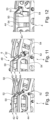
- FIG. 10 to 12 another section of the collecting wheel 4 is shown, in which Figures 11 and 12 in each case parts of the third receiving element 44 are hidden.
- Magnetic elements in the form of permanent magnets 52 are formed on the first and third receiving elements 42, 44 in the region of the receiving positions 6.
- the receiving positions 6 also advantageously comprise support surfaces 53 in which the longitudinal wires 7 can be stored and against which a longitudinal wire 7 is pressed by the clamping surface 51 in a closed position of the clamping element 50 and is thus fixed.
- Buffer elements 54 are advantageously arranged on the clamping element 50, by means of which a dimensional difference of the longitudinal wires 7 arranged on the collecting wheel 4 can be compensated, in particular in diameter.
- a longitudinal wire 7 is advantageously clamped by a relative movement, in particular by a rotation of the second receiving element 43 relative to the first and second receiving elements 42, 44. The relative movement is caused, for example, by a lifting movement of the pneumatic cylinder 59.
- FIG 13 a possible process sequence for equipping a basket welding machine 15 with a slide-in device 1 is shown.
- the slide-in device 1 according to Figure 13 comprises two collecting wheels 56, 57.
- the insertion device 1 is equipped with longitudinal wires 7.
- the feed device (not shown) is advantageously stationary and always equips at the same place. Rather, the collecting wheels of the insertion device 1 rotate the receiving positions 6 around the rotation axis D of the insertion device 1 by one position as soon as a receiving position 6 is equipped with a longitudinal wire 7 ( Figure II, Figure 13 ).
- the production of a basket 55 is advantageously carried out by the basket welding machine 15.
- the already produced basket 55 is advantageously removed ( Figures III-V, Figure 13 ) If the collecting wheels have moved so close to the main wheel 16 of the basket welding machine 15 that the longitudinal wires 7 are at least partially inserted into the wire guide tubes 25, a second collecting wheel 56 clamps, for example the longitudinal wires 7, so that a first collecting wheel 57 can move back along the axis of rotation D ( Figure V, Figure 13 ). It is also conceivable that the first collecting wheel 57 remains stationary, possibly releasing a fixation of the longitudinal wires 7 and the second collecting wheel 56 transports the longitudinal wires 7 further in the direction of the basket welding machine 15.
- both collecting wheels 56, 57 advantageously fix the longitudinal wires 7 and, in a next step, transport the longitudinal wires 7 along the rotation axis D in the direction of the basket welding machine 15 ( Figure VI, Figure 13 ).
- the second collecting wheel 56 is moved back into a loading position for reloading with longitudinal wires 7.
- the transport carriage 17 is brought up to the longitudinal wires 7 introduced into the basket welding machine 15 ( Figure VIII, Figure 13 ) .
- the transport carriage 17 pushes the longitudinal wires 7 along the rotation axis D back towards the first collecting wheel 57 until the ends 58 of the longitudinal wires 7 are introduced into the basket welding machine 15 at the same distance in the direction of the transport carriage 17 ( Figure IX, Figure 13 ).
- the first collecting wheel 57 fixes the longitudinal wires 7 so that the transport carriage 17 grips the longitudinal wires at the ends 58 without changing the position of the longitudinal wires along the rotation axis D. can. If the transport carriage 17 has fixed the longitudinal wires 7 at their ends 58, the first collecting wheel 57 releases the fixation with the longitudinal wires 7 and is moved back to a loading position for re-loading with longitudinal wires 7 ( Figure X, Figure 13 ).
Landscapes
- Engineering & Computer Science (AREA)
- Mechanical Engineering (AREA)
- Physics & Mathematics (AREA)
- Optics & Photonics (AREA)
- Plasma & Fusion (AREA)
- Wire Processing (AREA)
Claims (13)
- Dispositif pour équiper une machine à souder les paniers (15), le dispositif présentant un appareil d'insertion (1), l'appareil d'insertion (1) présentant un élément de réception (4) pour recevoir des fils longitudinaux (7) d'un panier (55) à fabriquer avec la machine à souder les paniers (15), l'appareil d'insertion (1) possédant une pluralité de positions de réception (6) pour tous les fils longitudinaux (7) du panier (55) sur l'élément de réception (4), les positions de réception (6) étant présentes dans la direction radiale à une distance d'un axe de rotation D de l'appareil d'insertion (1), l'appareil d'insertion (1) étant réalisé pour amener simultanément à la machine à souder les paniers (15), lors d'une opération d'insertion, au moins deux fils longitudinaux (7) agencés sur l'appareil d'insertion (1), l'opération d'insertion des fils longitudinaux (7) sur la machine à souder les paniers (15) étant effectuée par un mouvement de l'appareil d'insertion (1) dans la direction axiale de l'axe de rotation D de l'appareil d'insertion (1), caractérisé en ce que deux éléments de réception (4) sont présents, les éléments de réception (4) comprenant les positions de réception (6), les deux éléments de réception (4) étant présents de manière coulissante dans une direction axiale par rapport à l'axe de rotation D de l'appareil d'insertion (1).
- Dispositif pour équiper une machine à souder les paniers (15) selon la revendication 1, caractérisé en ce que le dispositif présente un dispositif d'amenée (2), le dispositif d'amenée (2) présentant un bâti de stockage (9), un appareil de séparation (10), un dispositif de transport (11) et/ou un dispositif de transfert (12) et étant réalisé pour amener des fils longitudinaux (7) à l'appareil d'insertion (1), l'appareil d'insertion (1) étant réalisé pour pouvoir être équipé du fil longitudinal (7) par un mouvement du fil longitudinal (7) dans une direction transversale à l'axe de rotation D de l'appareil d'insertion (1) et le dispositif d'amenée (2) équipant l'appareil d'insertion (1) par le côté.
- Dispositif pour équiper une machine à souder les paniers (15) selon l'une quelconque des revendications précédentes, caractérisé en ce qu'un élément de réception (4) présente un élément de support (5), l'élément de réception (4) étant monté de manière rotative sur l'élément de support (5).
- Dispositif pour équiper une machine à souder les paniers (15) selon l'une quelconque des revendications précédentes, caractérisé en ce qu'un élément de réception (4) comprend des éléments de serrage (50), les éléments de serrage (50) étant réalisés pour serrer les fils longitudinaux (7) montés sur l'élément de réception (4).
- Dispositif selon l'une quelconque des revendications précédentes, caractérisé en ce que l'appareil d'insertion (1) présente un arbre (27), l'arbre (27) et au moins un élément de réception (4) étant reliés entre eux de manière solidaire en rotation, de telle sorte qu'un mouvement de rotation de l'arbre (27) provoque un mouvement de rotation de l'élément de réception (4).
- Dispositif selon l'une quelconque des revendications précédentes, caractérisé en ce que, dans la zone de la position de réception (6), un élément magnétique (52) est présent pour maintenir magnétiquement un fil longitudinal (7) agencé sur un élément de réception (4).
- Dispositif selon l'une quelconque des revendications précédentes, caractérisé en ce que trois éléments de réception (4) sont présents.
- Dispositif selon l'une quelconque des revendications précédentes, caractérisé en ce que la position de réception (6) comprend une ouverture de réception (48) pour recevoir un fil longitudinal (7), de telle sorte que le fil longitudinal (7) peut être agencé latéralement contre l'appareil d'insertion (1).
- Dispositif selon l'une quelconque des revendications précédentes, caractérisé en ce que le dispositif de transport (11) est réalisé sous la forme d'un élévateur sans fin.
- Dispositif selon l'une quelconque des revendications précédentes, caractérisé en ce qu'un réservoir d'accumulation est agencé sur un élément de réception de l'appareil d'insertion de telle sorte que le réservoir d'accumulation est présent sur l'élément de réception conjointement avec d'autres éléments de l'élément de réception de manière rotative autour de l'axe de rotation D de l'appareil d'insertion, le réservoir d'accumulation étant réalisé sous la forme d'une cuve.
- Machine à souder les paniers (15) avec un dispositif pour équiper la machine à souder les paniers (15) selon l'une quelconque des revendications 1 à 10 précédentes, caractérisée en ce que l'axe de rotation D de l'appareil d'insertion (1) est monté sur la machine à souder les paniers (15).
- Machine à souder les paniers (15) selon la revendication 11, caractérisée en ce que des éléments de maintien (39) sont présents sur des tubes d'amenée de fils (25) de la machine à souder les paniers (15) pour serrer les fils longitudinaux (7).
- Machine à souder les paniers (15) selon la revendication 11 ou 12, caractérisée en ce qu'un réservoir d'accumulation est agencé sur une roue d'avance de la machine à souder les paniers de telle sorte que le réservoir d'accumulation est présent sur la roue d'avance, conjointement avec d'autres éléments de la roue d'avance, de manière rotative autour d'un axe de rotation de la machine à souder les paniers, le réservoir d'accumulation étant réalisé sous la forme d'une cuve.
Priority Applications (1)
| Application Number | Priority Date | Filing Date | Title |
|---|---|---|---|
| EP24160270.5A EP4357045A3 (fr) | 2019-04-04 | 2019-04-04 | Dispositif de montage d'une machine de soudage de panier |
Applications Claiming Priority (1)
| Application Number | Priority Date | Filing Date | Title |
|---|---|---|---|
| PCT/EP2019/058549 WO2020200466A1 (fr) | 2019-04-04 | 2019-04-04 | Dispositif pour l'équipement d'une machine à souder les paniers et machine à souder les paniers |
Related Child Applications (2)
| Application Number | Title | Priority Date | Filing Date |
|---|---|---|---|
| EP24160270.5A Division EP4357045A3 (fr) | 2019-04-04 | 2019-04-04 | Dispositif de montage d'une machine de soudage de panier |
| EP24160270.5A Division-Into EP4357045A3 (fr) | 2019-04-04 | 2019-04-04 | Dispositif de montage d'une machine de soudage de panier |
Publications (2)
| Publication Number | Publication Date |
|---|---|
| EP3946775A1 EP3946775A1 (fr) | 2022-02-09 |
| EP3946775B1 true EP3946775B1 (fr) | 2024-07-31 |
Family
ID=66102699
Family Applications (2)
| Application Number | Title | Priority Date | Filing Date |
|---|---|---|---|
| EP19716867.7A Active EP3946775B1 (fr) | 2019-04-04 | 2019-04-04 | Dispositif pour l'équipement d'une machine à souder les paniers et machine à souder les paniers |
| EP24160270.5A Pending EP4357045A3 (fr) | 2019-04-04 | 2019-04-04 | Dispositif de montage d'une machine de soudage de panier |
Family Applications After (1)
| Application Number | Title | Priority Date | Filing Date |
|---|---|---|---|
| EP24160270.5A Pending EP4357045A3 (fr) | 2019-04-04 | 2019-04-04 | Dispositif de montage d'une machine de soudage de panier |
Country Status (5)
| Country | Link |
|---|---|
| US (2) | US11931794B2 (fr) |
| EP (2) | EP3946775B1 (fr) |
| KR (1) | KR102628800B1 (fr) |
| CN (2) | CN113677453B (fr) |
| WO (1) | WO2020200466A1 (fr) |
Families Citing this family (2)
| Publication number | Priority date | Publication date | Assignee | Title |
|---|---|---|---|---|
| EP3946775B1 (fr) * | 2019-04-04 | 2024-07-31 | MBK MASCHINENBAU GmbH | Dispositif pour l'équipement d'une machine à souder les paniers et machine à souder les paniers |
| CN119347047B (zh) * | 2024-10-29 | 2025-10-24 | 无锡华立聚能装备股份有限公司 | 一种大型反应器加工用氩弧焊接送丝机构 |
Family Cites Families (44)
| Publication number | Priority date | Publication date | Assignee | Title |
|---|---|---|---|---|
| US1871751A (en) * | 1931-06-05 | 1932-08-16 | Westinghouse Electric & Mfg Co | Cage making machine |
| GB525485A (en) * | 1938-02-24 | 1940-08-29 | Wellington Concrete Pipe Compa | Improved means for use in the manufacture of electrically welded wire frames |
| US3254681A (en) * | 1962-06-25 | 1966-06-07 | Jr Leroy Magers | Reinforcing cage apparatus and method of making |
| US3579259A (en) * | 1969-06-23 | 1971-05-18 | Nippon Rocla Pipes Co Ltd | Apparatus for making a double-layer reinforcing cage for concrete pipes |
| DE2008095B2 (de) * | 1970-02-21 | 1975-10-16 | Wehrle-Werk Ag, 7830 Emmendingen | Wickelmaschine zur Herstellung von Ar mierungskorben mit Glockenmuffe |
| FR2080683B1 (fr) * | 1970-02-21 | 1975-07-04 | Wehrle Werk Ag | |
| US3678971A (en) * | 1970-07-15 | 1972-07-25 | W E Dunn Mfg Co | Apparatus and method for cage rolling and welding |
| SU556876A1 (ru) | 1975-02-19 | 1977-05-05 | Востряковский Завод Железобетонных Конструкций Дск-3 Ордена Ленина Главмосстроя | Лини дл контактной точечной сварки пространственных арматурных каркасов |
| SU577071A1 (ru) | 1976-06-24 | 1977-10-25 | Минский Филиал Конструкторско-Технологического Бюро "Стройиндустрия" | Машина дл контактной точечной сварки пространственных арматурных каркасов |
| US4314129A (en) * | 1979-02-12 | 1982-02-02 | Houston Well Screen Company | Method and apparatus for making well screen |
| SU1142244A1 (ru) * | 1983-01-03 | 1985-02-28 | Центральный Ордена Трудового Красного Знамени Научно-Исследовательский И Проектный Институт Типового И Экспериментального Проектирования Жилища | Лини дл изготовлени пространственных арматурных каркасов |
| JPS59214523A (ja) * | 1983-05-20 | 1984-12-04 | Hitachi Ltd | 熱交換器等のu字管の自動插入装置 |
| WO1985005053A1 (fr) * | 1984-04-30 | 1985-11-21 | Howard Bruce | Appareil de fabrication d'etriers de renforcement de beton et leur soudage avec des tiges pour former une cage de renforcement de beton |
| AT384969B (de) * | 1986-04-02 | 1988-02-10 | Evg Entwicklung Verwert Ges | Vielpunkt-widerstandsschweissmaschine |
| AT395386B (de) | 1988-05-26 | 1992-12-10 | Evg Entwicklung Verwert Ges | Verfahren und anlage zum herstellen zweilagiger geschweisster gitterkoerper |
| US5113730A (en) * | 1988-06-13 | 1992-05-19 | Paul Ducanis | Bar stock guide arrangement for screw machines |
| JPH0681652B2 (ja) * | 1988-07-01 | 1994-10-19 | 日本コンクリート工業株式会社 | 篭型鉄筋編成機の縦筋供給方法及び装置 |
| AT400934B (de) * | 1988-11-30 | 1996-04-25 | Evg Entwicklung Verwert Ges | Verfahren und anlage zum zuführen von längselementen aus rund- oder flachmaterial zu einer durchlauf-schweissmaschine für gitter oder gitterroste |
| US5228191A (en) * | 1989-10-16 | 1993-07-20 | Richard Casterline | Apparatus for making a barrel type fluid heat exchanger |
| AT396882B (de) * | 1990-03-30 | 1993-12-27 | Evg Entwicklung Verwert Ges | Doppelpunktschweissmaschine |
| ES2082249T3 (es) * | 1992-03-07 | 1996-03-16 | Mbk Maschinenbau Gmbh | Maquina y procedimiento para fabricar jaulas de refuerzo para tubos de hormigon. |
| JP2684541B2 (ja) * | 1993-09-30 | 1997-12-03 | 株式会社長谷工コーポレーション | X形配筋組立鉄筋の製造装置 |
| JP2587905B2 (ja) * | 1994-04-12 | 1997-03-05 | 株式会社松村組 | 鉄筋籠製造装置 |
| JP3300609B2 (ja) * | 1996-08-07 | 2002-07-08 | 株式会社東芝 | 熱交換器の熱交換用チューブ組立て装置および組立て方法 |
| AUPP758898A0 (en) * | 1998-12-10 | 1999-01-07 | Barden, Wayne | An apparatus for making reinforcing cages for reinforcing concrete |
| GB9928264D0 (en) * | 1999-12-01 | 2000-01-26 | Neckoula Kamal | Cage making machine |
| EP1428596A1 (fr) * | 2002-12-09 | 2004-06-16 | H.A. Schlatter Ag | Installation pour la fabrication de grilles en fils de fer |
| WO2005084848A1 (fr) * | 2004-03-02 | 2005-09-15 | M.E.P. Macchine Elettroniche Piegatrici Spa | Machine a produire des cages d'armature, et procede de production s'y rapportant |
| DE102004041736A1 (de) * | 2004-08-28 | 2006-03-02 | Ed. Züblin Ag | Maschine zur kontinuierlichen Herstellung von Bewehrungskörben, besonders mit nichtkreisförmigem Querschnitt |
| ITUD20050169A1 (it) * | 2005-10-11 | 2007-04-12 | Piegatrici Macch Elettr | Macchina e procedimento per la produzione di gabbie di armatura |
| ITUD20060073A1 (it) * | 2006-03-22 | 2007-09-23 | Awm Spa | "gruppo automatico di piegatura ed inserimento barre di rinforzo nelle gabbie metalliche di armatura gia' preformate" |
| WO2008131346A2 (fr) * | 2007-04-20 | 2008-10-30 | Concrete Technology Worldwide, Inc. | Procédé et système de fabrication d'une cage grillagée |
| IT1391697B1 (it) * | 2008-11-07 | 2012-01-17 | Beta Systems S R L Ora Beta Systems S R L A Socio Unico | Macchina per la formazione di rete metallica e relativo gruppo di saldatura |
| US8533956B2 (en) * | 2009-11-25 | 2013-09-17 | Jack Perry | Rebar installation system and method of securing rebar |
| IT1402456B1 (it) * | 2010-10-25 | 2013-09-13 | Schnell Spa | Macchina per realizzare gabbie metalliche. |
| EP2996827A1 (fr) * | 2013-05-17 | 2016-03-23 | Schnell S.p.A. | Appareil et procédé pour fabriquer des cages métalliques pour des piliers coniques |
| AU2016221340B2 (en) | 2015-02-18 | 2020-12-17 | M.E.P. Macchine Elettroniche Piegatrici S.P.A. | Apparatus and method for feeding bars |
| US9586762B1 (en) * | 2015-04-01 | 2017-03-07 | S&M Precast Inc. | Rotatable long-bar handling apparatus |
| WO2017153602A1 (fr) * | 2016-03-11 | 2017-09-14 | Apilion Machines + Services Gmbh | Dispositif de fabrication de cages d'armature |
| CN108326208A (zh) * | 2017-12-31 | 2018-07-27 | 山东连环机械科技有限公司 | 盾构管片钢筋笼智能成型生产线 |
| CN208427908U (zh) * | 2018-05-19 | 2019-01-25 | 中铁十局集团青岛工程有限公司 | 移动盘及应用该移动盘的钢筋笼滚焊机 |
| CN108941396A (zh) * | 2018-10-19 | 2018-12-07 | 广东华岩建材有限公司 | 一种管桩钢筋笼的生产系统 |
| EP3946775B1 (fr) * | 2019-04-04 | 2024-07-31 | MBK MASCHINENBAU GmbH | Dispositif pour l'équipement d'une machine à souder les paniers et machine à souder les paniers |
| DE202019101960U1 (de) * | 2019-04-04 | 2019-05-08 | Mbk Maschinenbau Gmbh | Vorrichtung zur Bestückung einer Korbschweißmaschine |
-
2019
- 2019-04-04 EP EP19716867.7A patent/EP3946775B1/fr active Active
- 2019-04-04 KR KR1020217031234A patent/KR102628800B1/ko active Active
- 2019-04-04 WO PCT/EP2019/058549 patent/WO2020200466A1/fr not_active Ceased
- 2019-04-04 CN CN201980095203.4A patent/CN113677453B/zh active Active
- 2019-04-04 EP EP24160270.5A patent/EP4357045A3/fr active Pending
- 2019-04-04 CN CN202410277980.3A patent/CN118180748A/zh active Pending
-
2021
- 2021-10-01 US US17/449,678 patent/US11931794B2/en active Active
-
2024
- 2024-02-12 US US18/438,572 patent/US12544827B2/en active Active
Also Published As
| Publication number | Publication date |
|---|---|
| CN113677453B (zh) | 2025-01-07 |
| EP3946775A1 (fr) | 2022-02-09 |
| CN118180748A (zh) | 2024-06-14 |
| EP4357045A3 (fr) | 2024-07-31 |
| KR102628800B1 (ko) | 2024-01-23 |
| US20220016692A1 (en) | 2022-01-20 |
| CN113677453A (zh) | 2021-11-19 |
| KR20210148149A (ko) | 2021-12-07 |
| US11931794B2 (en) | 2024-03-19 |
| US20240189885A1 (en) | 2024-06-13 |
| US12544827B2 (en) | 2026-02-10 |
| WO2020200466A1 (fr) | 2020-10-08 |
| EP4357045A2 (fr) | 2024-04-24 |
Similar Documents
| Publication | Publication Date | Title |
|---|---|---|
| EP1955789B1 (fr) | Cintreuse | |
| DE102010003085B4 (de) | Vorrichtung und Verfahren zum Zuführen und Befestigen von Ausgleichselementen für den Unwuchtausgleich in einer Auswuchtmaschine | |
| EP0561007B1 (fr) | Machine et procédé pour la fabrication des cages d'armature pour les tubes en béton | |
| DE4037031A1 (de) | Rohrschneidemaschine | |
| EP1567365A1 (fr) | Dispositif de serrage de jantes servant en particulier a monter des pneus | |
| EP3946775B1 (fr) | Dispositif pour l'équipement d'une machine à souder les paniers et machine à souder les paniers | |
| DE19630023A1 (de) | Einrichtung zum Verformen von stabförmigen Bauteilen | |
| DE3408734C2 (fr) | ||
| DE102009035839A1 (de) | Vorrichtung zum mechanischen Bearbeiten von rohr- oder stangenförmigen Werkstücken | |
| DE1966672B2 (de) | Vorrichtung zur Herstellung eines Bewehrungskäfigs für Spannbetonrohre | |
| DE2313417C3 (de) | Vorrichtung zum Herstellen von verdrallten Leitungsdrahtpaaren und Verfahren zum Verdrallen von Leitungsdrahtpaaren | |
| EP2826739B1 (fr) | Procédé et dispositif de positionnement de douilles sur un arbre d'enroulement | |
| DE202019101960U1 (de) | Vorrichtung zur Bestückung einer Korbschweißmaschine | |
| DE3204668A1 (de) | Verfahren und vorrichtung zur herstellung von riemenscheiben | |
| DE2515344C2 (de) | Vorrichtung zum fortlaufenden Herstellen von Wulstdraht-Ringen | |
| DE3115481C2 (de) | Werkstückpaletten-Speicher für ein Bearbeitungszentrum | |
| DE2557370C3 (de) | Verfahren und Einrichtung zum aufeinanderfolgenden induktiven Erwärmen von länglichen Werkstücken, wie insbesondere Achsen, Wellen u.dgl | |
| DE3018628A1 (de) | Vorrichtung zum automatischen aufwickeln von stranggut, insbesondere von draht | |
| EP1332814A2 (fr) | Dispositif d'avancement d'une barre pour tours d'usinage | |
| EP0310989B1 (fr) | Procédé et appareil pour enlever des tôles d'une pile | |
| DE2617608A1 (de) | Werkzeugmaschine mit einer automatischen werkzeugwechseleinrichtung | |
| DE1922320C3 (de) | Werkzeugwechselvorrichtung | |
| DE4403919C2 (de) | Verfahren und Vorrichtung zum Wickeln von Spulen für elektrische Motoren oder Generatoren | |
| DE102012210228A1 (de) | Vorrichtung zum Trennen eines endlosen zugeführten Stranges eines Produktes der Tabak verarbeitenden Industrie in einzelne Stäbe | |
| EP3600712A1 (fr) | Installation de dressage de fils et procédé pour le dressage de fils au moyen de l'installation de dressage de fils |
Legal Events
| Date | Code | Title | Description |
|---|---|---|---|
| STAA | Information on the status of an ep patent application or granted ep patent |
Free format text: STATUS: UNKNOWN |
|
| STAA | Information on the status of an ep patent application or granted ep patent |
Free format text: STATUS: THE INTERNATIONAL PUBLICATION HAS BEEN MADE |
|
| PUAI | Public reference made under article 153(3) epc to a published international application that has entered the european phase |
Free format text: ORIGINAL CODE: 0009012 |
|
| STAA | Information on the status of an ep patent application or granted ep patent |
Free format text: STATUS: REQUEST FOR EXAMINATION WAS MADE |
|
| 17P | Request for examination filed |
Effective date: 20211007 |
|
| AK | Designated contracting states |
Kind code of ref document: A1 Designated state(s): AL AT BE BG CH CY CZ DE DK EE ES FI FR GB GR HR HU IE IS IT LI LT LU LV MC MK MT NL NO PL PT RO RS SE SI SK SM TR |
|
| DAV | Request for validation of the european patent (deleted) | ||
| DAX | Request for extension of the european patent (deleted) | ||
| P01 | Opt-out of the competence of the unified patent court (upc) registered |
Effective date: 20230505 |
|
| STAA | Information on the status of an ep patent application or granted ep patent |
Free format text: STATUS: EXAMINATION IS IN PROGRESS |
|
| 17Q | First examination report despatched |
Effective date: 20230922 |
|
| GRAJ | Information related to disapproval of communication of intention to grant by the applicant or resumption of examination proceedings by the epo deleted |
Free format text: ORIGINAL CODE: EPIDOSDIGR1 |
|
| STAA | Information on the status of an ep patent application or granted ep patent |
Free format text: STATUS: GRANT OF PATENT IS INTENDED |
|
| GRAP | Despatch of communication of intention to grant a patent |
Free format text: ORIGINAL CODE: EPIDOSNIGR1 |
|
| INTG | Intention to grant announced |
Effective date: 20240307 |
|
| GRAS | Grant fee paid |
Free format text: ORIGINAL CODE: EPIDOSNIGR3 |
|
| GRAA | (expected) grant |
Free format text: ORIGINAL CODE: 0009210 |
|
| STAA | Information on the status of an ep patent application or granted ep patent |
Free format text: STATUS: THE PATENT HAS BEEN GRANTED |
|
| AK | Designated contracting states |
Kind code of ref document: B1 Designated state(s): AL AT BE BG CH CY CZ DE DK EE ES FI FR GB GR HR HU IE IS IT LI LT LU LV MC MK MT NL NO PL PT RO RS SE SI SK SM TR |
|
| REG | Reference to a national code |
Ref country code: CH Ref legal event code: EP Ref country code: GB Ref legal event code: FG4D Free format text: NOT ENGLISH |
|
| REG | Reference to a national code |
Ref country code: DE Ref legal event code: R096 Ref document number: 502019011785 Country of ref document: DE |
|
| REG | Reference to a national code |
Ref country code: IE Ref legal event code: FG4D Free format text: LANGUAGE OF EP DOCUMENT: GERMAN |
|
| REG | Reference to a national code |
Ref country code: LT Ref legal event code: MG9D |
|
| REG | Reference to a national code |
Ref country code: NL Ref legal event code: MP Effective date: 20240731 |
|
| PG25 | Lapsed in a contracting state [announced via postgrant information from national office to epo] |
Ref country code: PT Free format text: LAPSE BECAUSE OF FAILURE TO SUBMIT A TRANSLATION OF THE DESCRIPTION OR TO PAY THE FEE WITHIN THE PRESCRIBED TIME-LIMIT Effective date: 20241202 |
|
| REG | Reference to a national code |
Ref country code: GR Ref legal event code: EP Ref document number: 20240402460 Country of ref document: GR Effective date: 20241209 |
|
| PG25 | Lapsed in a contracting state [announced via postgrant information from national office to epo] |
Ref country code: PT Free format text: LAPSE BECAUSE OF FAILURE TO SUBMIT A TRANSLATION OF THE DESCRIPTION OR TO PAY THE FEE WITHIN THE PRESCRIBED TIME-LIMIT Effective date: 20241202 |
|
| PG25 | Lapsed in a contracting state [announced via postgrant information from national office to epo] |
Ref country code: NO Free format text: LAPSE BECAUSE OF FAILURE TO SUBMIT A TRANSLATION OF THE DESCRIPTION OR TO PAY THE FEE WITHIN THE PRESCRIBED TIME-LIMIT Effective date: 20241031 |
|
| PG25 | Lapsed in a contracting state [announced via postgrant information from national office to epo] |
Ref country code: NL Free format text: LAPSE BECAUSE OF FAILURE TO SUBMIT A TRANSLATION OF THE DESCRIPTION OR TO PAY THE FEE WITHIN THE PRESCRIBED TIME-LIMIT Effective date: 20240731 Ref country code: FI Free format text: LAPSE BECAUSE OF FAILURE TO SUBMIT A TRANSLATION OF THE DESCRIPTION OR TO PAY THE FEE WITHIN THE PRESCRIBED TIME-LIMIT Effective date: 20240731 Ref country code: PL Free format text: LAPSE BECAUSE OF FAILURE TO SUBMIT A TRANSLATION OF THE DESCRIPTION OR TO PAY THE FEE WITHIN THE PRESCRIBED TIME-LIMIT Effective date: 20240731 |
|
| PG25 | Lapsed in a contracting state [announced via postgrant information from national office to epo] |
Ref country code: BG Free format text: LAPSE BECAUSE OF FAILURE TO SUBMIT A TRANSLATION OF THE DESCRIPTION OR TO PAY THE FEE WITHIN THE PRESCRIBED TIME-LIMIT Effective date: 20240731 |
|
| PG25 | Lapsed in a contracting state [announced via postgrant information from national office to epo] |
Ref country code: LV Free format text: LAPSE BECAUSE OF FAILURE TO SUBMIT A TRANSLATION OF THE DESCRIPTION OR TO PAY THE FEE WITHIN THE PRESCRIBED TIME-LIMIT Effective date: 20240731 |
|
| PG25 | Lapsed in a contracting state [announced via postgrant information from national office to epo] |
Ref country code: IS Free format text: LAPSE BECAUSE OF FAILURE TO SUBMIT A TRANSLATION OF THE DESCRIPTION OR TO PAY THE FEE WITHIN THE PRESCRIBED TIME-LIMIT Effective date: 20241130 |
|
| PG25 | Lapsed in a contracting state [announced via postgrant information from national office to epo] |
Ref country code: HR Free format text: LAPSE BECAUSE OF FAILURE TO SUBMIT A TRANSLATION OF THE DESCRIPTION OR TO PAY THE FEE WITHIN THE PRESCRIBED TIME-LIMIT Effective date: 20240731 |
|
| PG25 | Lapsed in a contracting state [announced via postgrant information from national office to epo] |
Ref country code: RS Free format text: LAPSE BECAUSE OF FAILURE TO SUBMIT A TRANSLATION OF THE DESCRIPTION OR TO PAY THE FEE WITHIN THE PRESCRIBED TIME-LIMIT Effective date: 20241031 Ref country code: ES Free format text: LAPSE BECAUSE OF FAILURE TO SUBMIT A TRANSLATION OF THE DESCRIPTION OR TO PAY THE FEE WITHIN THE PRESCRIBED TIME-LIMIT Effective date: 20240731 |
|
| PG25 | Lapsed in a contracting state [announced via postgrant information from national office to epo] |
Ref country code: RS Free format text: LAPSE BECAUSE OF FAILURE TO SUBMIT A TRANSLATION OF THE DESCRIPTION OR TO PAY THE FEE WITHIN THE PRESCRIBED TIME-LIMIT Effective date: 20241031 Ref country code: PL Free format text: LAPSE BECAUSE OF FAILURE TO SUBMIT A TRANSLATION OF THE DESCRIPTION OR TO PAY THE FEE WITHIN THE PRESCRIBED TIME-LIMIT Effective date: 20240731 Ref country code: NO Free format text: LAPSE BECAUSE OF FAILURE TO SUBMIT A TRANSLATION OF THE DESCRIPTION OR TO PAY THE FEE WITHIN THE PRESCRIBED TIME-LIMIT Effective date: 20241031 Ref country code: NL Free format text: LAPSE BECAUSE OF FAILURE TO SUBMIT A TRANSLATION OF THE DESCRIPTION OR TO PAY THE FEE WITHIN THE PRESCRIBED TIME-LIMIT Effective date: 20240731 Ref country code: LV Free format text: LAPSE BECAUSE OF FAILURE TO SUBMIT A TRANSLATION OF THE DESCRIPTION OR TO PAY THE FEE WITHIN THE PRESCRIBED TIME-LIMIT Effective date: 20240731 Ref country code: IS Free format text: LAPSE BECAUSE OF FAILURE TO SUBMIT A TRANSLATION OF THE DESCRIPTION OR TO PAY THE FEE WITHIN THE PRESCRIBED TIME-LIMIT Effective date: 20241130 Ref country code: HR Free format text: LAPSE BECAUSE OF FAILURE TO SUBMIT A TRANSLATION OF THE DESCRIPTION OR TO PAY THE FEE WITHIN THE PRESCRIBED TIME-LIMIT Effective date: 20240731 Ref country code: FI Free format text: LAPSE BECAUSE OF FAILURE TO SUBMIT A TRANSLATION OF THE DESCRIPTION OR TO PAY THE FEE WITHIN THE PRESCRIBED TIME-LIMIT Effective date: 20240731 Ref country code: ES Free format text: LAPSE BECAUSE OF FAILURE TO SUBMIT A TRANSLATION OF THE DESCRIPTION OR TO PAY THE FEE WITHIN THE PRESCRIBED TIME-LIMIT Effective date: 20240731 Ref country code: BG Free format text: LAPSE BECAUSE OF FAILURE TO SUBMIT A TRANSLATION OF THE DESCRIPTION OR TO PAY THE FEE WITHIN THE PRESCRIBED TIME-LIMIT Effective date: 20240731 |
|
| REG | Reference to a national code |
Ref country code: DE Ref legal event code: R082 Ref document number: 502019011785 Country of ref document: DE Representative=s name: RAVENSPAT PATENTANWAELTE PARTNERSCHAFT MBB, DE |
|
| PG25 | Lapsed in a contracting state [announced via postgrant information from national office to epo] |
Ref country code: DK Free format text: LAPSE BECAUSE OF FAILURE TO SUBMIT A TRANSLATION OF THE DESCRIPTION OR TO PAY THE FEE WITHIN THE PRESCRIBED TIME-LIMIT Effective date: 20240731 Ref country code: RO Free format text: LAPSE BECAUSE OF FAILURE TO SUBMIT A TRANSLATION OF THE DESCRIPTION OR TO PAY THE FEE WITHIN THE PRESCRIBED TIME-LIMIT Effective date: 20240731 Ref country code: SM Free format text: LAPSE BECAUSE OF FAILURE TO SUBMIT A TRANSLATION OF THE DESCRIPTION OR TO PAY THE FEE WITHIN THE PRESCRIBED TIME-LIMIT Effective date: 20240731 |
|
| PG25 | Lapsed in a contracting state [announced via postgrant information from national office to epo] |
Ref country code: EE Free format text: LAPSE BECAUSE OF FAILURE TO SUBMIT A TRANSLATION OF THE DESCRIPTION OR TO PAY THE FEE WITHIN THE PRESCRIBED TIME-LIMIT Effective date: 20240731 |
|
| PG25 | Lapsed in a contracting state [announced via postgrant information from national office to epo] |
Ref country code: CZ Free format text: LAPSE BECAUSE OF FAILURE TO SUBMIT A TRANSLATION OF THE DESCRIPTION OR TO PAY THE FEE WITHIN THE PRESCRIBED TIME-LIMIT Effective date: 20240731 |
|
| PG25 | Lapsed in a contracting state [announced via postgrant information from national office to epo] |
Ref country code: SK Free format text: LAPSE BECAUSE OF FAILURE TO SUBMIT A TRANSLATION OF THE DESCRIPTION OR TO PAY THE FEE WITHIN THE PRESCRIBED TIME-LIMIT Effective date: 20240731 |
|
| REG | Reference to a national code |
Ref country code: DE Ref legal event code: R097 Ref document number: 502019011785 Country of ref document: DE |
|
| PLBE | No opposition filed within time limit |
Free format text: ORIGINAL CODE: 0009261 |
|
| STAA | Information on the status of an ep patent application or granted ep patent |
Free format text: STATUS: NO OPPOSITION FILED WITHIN TIME LIMIT |
|
| 26N | No opposition filed |
Effective date: 20250501 |
|
| PGFP | Annual fee paid to national office [announced via postgrant information from national office to epo] |
Ref country code: DE Payment date: 20250417 Year of fee payment: 7 |
|
| PGFP | Annual fee paid to national office [announced via postgrant information from national office to epo] |
Ref country code: IT Payment date: 20250430 Year of fee payment: 7 |
|
| PGFP | Annual fee paid to national office [announced via postgrant information from national office to epo] |
Ref country code: GR Payment date: 20250416 Year of fee payment: 7 |
|
| PGFP | Annual fee paid to national office [announced via postgrant information from national office to epo] |
Ref country code: AT Payment date: 20250416 Year of fee payment: 7 |
|
| PG25 | Lapsed in a contracting state [announced via postgrant information from national office to epo] |
Ref country code: SE Free format text: LAPSE BECAUSE OF FAILURE TO SUBMIT A TRANSLATION OF THE DESCRIPTION OR TO PAY THE FEE WITHIN THE PRESCRIBED TIME-LIMIT Effective date: 20240731 |
|
| REG | Reference to a national code |
Ref country code: CH Ref legal event code: H13 Free format text: ST27 STATUS EVENT CODE: U-0-0-H10-H13 (AS PROVIDED BY THE NATIONAL OFFICE) Effective date: 20251125 |
|
| PG25 | Lapsed in a contracting state [announced via postgrant information from national office to epo] |
Ref country code: LU Free format text: LAPSE BECAUSE OF NON-PAYMENT OF DUE FEES Effective date: 20250404 |
|
| PG25 | Lapsed in a contracting state [announced via postgrant information from national office to epo] |
Ref country code: MC Free format text: LAPSE BECAUSE OF FAILURE TO SUBMIT A TRANSLATION OF THE DESCRIPTION OR TO PAY THE FEE WITHIN THE PRESCRIBED TIME-LIMIT Effective date: 20240731 |
|
| GBPC | Gb: european patent ceased through non-payment of renewal fee |
Effective date: 20250404 |
|
| REG | Reference to a national code |
Ref country code: BE Ref legal event code: MM Effective date: 20250430 |
|
| PG25 | Lapsed in a contracting state [announced via postgrant information from national office to epo] |
Ref country code: GB Free format text: LAPSE BECAUSE OF NON-PAYMENT OF DUE FEES Effective date: 20250404 |
|
| PG25 | Lapsed in a contracting state [announced via postgrant information from national office to epo] |
Ref country code: FR Free format text: LAPSE BECAUSE OF NON-PAYMENT OF DUE FEES Effective date: 20250430 |
|
| PG25 | Lapsed in a contracting state [announced via postgrant information from national office to epo] |
Ref country code: BE Free format text: LAPSE BECAUSE OF NON-PAYMENT OF DUE FEES Effective date: 20250430 |
|
| PG25 | Lapsed in a contracting state [announced via postgrant information from national office to epo] |
Ref country code: CH Free format text: LAPSE BECAUSE OF NON-PAYMENT OF DUE FEES Effective date: 20250430 |
|
| PG25 | Lapsed in a contracting state [announced via postgrant information from national office to epo] |
Ref country code: IE Free format text: LAPSE BECAUSE OF NON-PAYMENT OF DUE FEES Effective date: 20250404 |