EP3953121B1 - Schalung zur herstellung eines betontübbings eines tunnelausbausystems - Google Patents
Schalung zur herstellung eines betontübbings eines tunnelausbausystems Download PDFInfo
- Publication number
- EP3953121B1 EP3953121B1 EP20721158.2A EP20721158A EP3953121B1 EP 3953121 B1 EP3953121 B1 EP 3953121B1 EP 20721158 A EP20721158 A EP 20721158A EP 3953121 B1 EP3953121 B1 EP 3953121B1
- Authority
- EP
- European Patent Office
- Prior art keywords
- formwork
- actuator
- closed position
- hydraulic circuit
- formwork according
- Prior art date
- Legal status (The legal status is an assumption and is not a legal conclusion. Google has not performed a legal analysis and makes no representation as to the accuracy of the status listed.)
- Active
Links
Images







Classifications
-
- B—PERFORMING OPERATIONS; TRANSPORTING
- B25—HAND TOOLS; PORTABLE POWER-DRIVEN TOOLS; MANIPULATORS
- B25J—MANIPULATORS; CHAMBERS PROVIDED WITH MANIPULATION DEVICES
- B25J11/00—Manipulators not otherwise provided for
-
- B—PERFORMING OPERATIONS; TRANSPORTING
- B25—HAND TOOLS; PORTABLE POWER-DRIVEN TOOLS; MANIPULATORS
- B25J—MANIPULATORS; CHAMBERS PROVIDED WITH MANIPULATION DEVICES
- B25J5/00—Manipulators mounted on wheels or on carriages
- B25J5/02—Manipulators mounted on wheels or on carriages travelling along a guideway
- B25J5/04—Manipulators mounted on wheels or on carriages travelling along a guideway wherein the guideway is also moved, e.g. travelling crane bridge type
-
- B—PERFORMING OPERATIONS; TRANSPORTING
- B25—HAND TOOLS; PORTABLE POWER-DRIVEN TOOLS; MANIPULATORS
- B25J—MANIPULATORS; CHAMBERS PROVIDED WITH MANIPULATION DEVICES
- B25J9/00—Program-controlled manipulators
- B25J9/0009—Constructional details, e.g. manipulator supports, bases
-
- B—PERFORMING OPERATIONS; TRANSPORTING
- B28—WORKING CEMENT, CLAY, OR STONE
- B28B—SHAPING CLAY OR OTHER CERAMIC COMPOSITIONS; SHAPING SLAG; SHAPING MIXTURES CONTAINING CEMENTITIOUS MATERIAL, e.g. PLASTER
- B28B11/00—Apparatus or processes for treating or working the shaped or preshaped articles
- B28B11/24—Apparatus or processes for treating or working the shaped or preshaped articles for curing, setting or hardening
- B28B11/245—Curing concrete articles
-
- B—PERFORMING OPERATIONS; TRANSPORTING
- B28—WORKING CEMENT, CLAY, OR STONE
- B28B—SHAPING CLAY OR OTHER CERAMIC COMPOSITIONS; SHAPING SLAG; SHAPING MIXTURES CONTAINING CEMENTITIOUS MATERIAL, e.g. PLASTER
- B28B15/00—General arrangement or layout of plant ; Industrial outlines or plant installations
-
- B—PERFORMING OPERATIONS; TRANSPORTING
- B28—WORKING CEMENT, CLAY, OR STONE
- B28B—SHAPING CLAY OR OTHER CERAMIC COMPOSITIONS; SHAPING SLAG; SHAPING MIXTURES CONTAINING CEMENTITIOUS MATERIAL, e.g. PLASTER
- B28B15/00—General arrangement or layout of plant ; Industrial outlines or plant installations
- B28B15/002—Mobile plants, e.g. on vehicles or on boats
-
- B—PERFORMING OPERATIONS; TRANSPORTING
- B28—WORKING CEMENT, CLAY, OR STONE
- B28B—SHAPING CLAY OR OTHER CERAMIC COMPOSITIONS; SHAPING SLAG; SHAPING MIXTURES CONTAINING CEMENTITIOUS MATERIAL, e.g. PLASTER
- B28B17/00—Details of, or accessories for, apparatus for shaping the material; Auxiliary measures taken in connection with such shaping
- B28B17/0063—Control arrangements
- B28B17/0081—Process control
-
- B—PERFORMING OPERATIONS; TRANSPORTING
- B28—WORKING CEMENT, CLAY, OR STONE
- B28B—SHAPING CLAY OR OTHER CERAMIC COMPOSITIONS; SHAPING SLAG; SHAPING MIXTURES CONTAINING CEMENTITIOUS MATERIAL, e.g. PLASTER
- B28B5/00—Producing shaped articles from the material in moulds or on moulding surfaces, carried or formed by, in or on conveyors irrespective of the manner of shaping
- B28B5/04—Producing shaped articles from the material in moulds or on moulding surfaces, carried or formed by, in or on conveyors irrespective of the manner of shaping in moulds moved in succession past one or more shaping stations
-
- B—PERFORMING OPERATIONS; TRANSPORTING
- B28—WORKING CEMENT, CLAY, OR STONE
- B28B—SHAPING CLAY OR OTHER CERAMIC COMPOSITIONS; SHAPING SLAG; SHAPING MIXTURES CONTAINING CEMENTITIOUS MATERIAL, e.g. PLASTER
- B28B7/00—Moulds; Cores; Mandrels
- B28B7/0002—Auxiliary parts or elements of the mould
- B28B7/0014—Fastening means for mould parts, e.g. for attaching mould walls on mould tables; Mould clamps
-
- B—PERFORMING OPERATIONS; TRANSPORTING
- B28—WORKING CEMENT, CLAY, OR STONE
- B28B—SHAPING CLAY OR OTHER CERAMIC COMPOSITIONS; SHAPING SLAG; SHAPING MIXTURES CONTAINING CEMENTITIOUS MATERIAL, e.g. PLASTER
- B28B7/00—Moulds; Cores; Mandrels
- B28B7/0029—Moulds or moulding surfaces not covered by B28B7/0058 - B28B7/36 and B28B7/40 - B28B7/465, e.g. moulds assembled from several parts
- B28B7/0035—Moulds characterised by the way in which the sidewalls of the mould and the moulded article move with respect to each other during demoulding
- B28B7/0044—Moulds characterised by the way in which the sidewalls of the mould and the moulded article move with respect to each other during demoulding the sidewalls of the mould being only tilted away from the sidewalls of the moulded article, e.g. moulds with hingedly mounted sidewalls
-
- B—PERFORMING OPERATIONS; TRANSPORTING
- B28—WORKING CEMENT, CLAY, OR STONE
- B28B—SHAPING CLAY OR OTHER CERAMIC COMPOSITIONS; SHAPING SLAG; SHAPING MIXTURES CONTAINING CEMENTITIOUS MATERIAL, e.g. PLASTER
- B28B7/00—Moulds; Cores; Mandrels
- B28B7/38—Treating surfaces of moulds, cores, or mandrels to prevent sticking
- B28B7/386—Cleaning
-
- E—FIXED CONSTRUCTIONS
- E21—EARTH OR ROCK DRILLING; MINING
- E21D—SHAFTS; TUNNELS; GALLERIES; LARGE UNDERGROUND CHAMBERS
- E21D11/00—Lining tunnels, galleries or other underground cavities, e.g. large underground chambers; Linings therefor; Making such linings in situ, e.g. by assembling
- E21D11/04—Lining with building materials
- E21D11/08—Lining with building materials with preformed concrete slabs
- E21D11/086—Methods of making concrete lining segments
Definitions
- the invention relates to a formwork for producing a concrete segment of a tunnel lining system according to the preamble of claim 1.
- JP 2001 047421 A discloses a formwork for producing a concrete segment of a tunnel lining system according to the preamble of claim 1.
- a further teaching of the invention provides that at least two walls touch one another at one of their two outer end areas with their short sides in the closed position, thereby forming a corner of the concrete tub. It is advantageous that a male engagement element is provided on one of the two walls in the outer end area and a female engagement element is provided on the other wall in the outer end area, which engage with one another when the two walls are in the closed position. This makes it easy to ensure that the corner is closed.
- the two walls are connected to one another in their outer end regions by means of at least one screw connection or a clamp connection, wherein the screw connection or clamp connection preferably serves to secure the position, and/or wherein the screw connection has a screw with a spring element arranged along at least part of the screw.
- a further teaching of the invention provides that the clamping connection has a locking element that is arranged on one of the wall elements and can be pivoted between an open and a closed position with at least one actuator, for example a hydraulic cylinder or a spindle system. It is advantageous that the actuator is connected to the drive system described below. This makes it easy to provide a lock.
- a further teaching of the invention provides that the at least one wall for moving between the open and the closed position is provided with at least two actuators of the drive system. This makes it easy to apply and distribute the necessary holding forces.
- a further teaching of the invention provides that the at least one wall element has two outer end regions and that at least one actuator is provided for each end region for moving and holding the wall element. It has been shown that this makes it particularly easy to ensure a tight seal even when the formwork is filled with concrete and the side walls are possibly deformed as a result.
- a further teaching of the invention provides that the drive system can be connected to an external drive for driving the drive system at a work station. This allows the construction of the formwork to be as simple as possible, since a drive in the formwork can be dispensed with.
- the drive system is a hydraulic system with at least one hydraulic circuit, wherein the drive system has at least one hydraulic cylinder as an actuator, which is connected to the hydraulic circuit. This makes it easy to provide both movement and holding with sufficient forces.
- the hydraulic circuit has a locking element for maintaining the pressure in the hydraulic circuit, which is preferably a load-bearing valve. It is also advantageous that the hydraulic circuit has an element for compensating for a pressure change and/or a volume change in the hydraulic circuit, which is preferably a blind cylinder or a diaphragm accumulator. It is also advantageous that the hydraulic circuit has at least one connection element for detachably connecting the hydraulic circuit to a hydraulic unit as an external drive of the drive system at a work station. It is also advantageous that the individual hydraulic cylinders are connected by means of pressure sequence valves.
- a hydraulic circuit according to the invention can be easily provided by at least one of the aforementioned elements.
- the drive system is a mechanical drive as an actuator, preferably a spindle drive. It is advantageous that the mechanical drive is designed to be self-locking or is provided with a locking element. It is also advantageous that the mechanical drive is a Connecting element for detachable connection to an external rotary drive, for example a torque screwdriver, as an external drive of the drive system at a workstation.
- At least one cover element is pivotably provided on the formwork, which can be arranged on the top of the concrete trough and at least partially covers the top.
- the cover element can be pivoted between an open and a closed position by at least one actuator, which is a hydraulic cylinder, which preferably holds the cover element in the respective position. It is also advantageous that the actuator is connected to the drive system described above.
- a further teaching of the invention provides that the cover element has a locking element which locks the cover element in the closed position relative to the formwork.
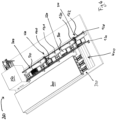
- Figure 1 to 4 show a production plant 100 for concrete segments 500 in which a formwork 10 according to the invention is used.
- the production plant 100 is designed, for example, as a circulation plant for the formwork 10.
- the formwork according to the invention can also be used in a stationary plant (not shown) in which the formwork remains in one place for the production steps before being introduced into a hardening plant for the accelerated initial hardening of the concrete segment 500, if this hardening is necessary.
- the circulation system shown here as an example consists of at least one production line 200 and a hardening tunnel 300.
- the hardening tunnel 300 has, for example, at least one hardening line 310, in Figure 1 shown three hardening lines 310.
- the production line 200 and the hardening tunnel 300 or its hardening lines 310 are connected to a cross conveyor 400.
- the production plant 100 has, for example, a transport path 110.
- the transport path 110 has, for example, a track 111 on which the formwork 10 can be moved.
- the formwork either has its own means of transport, for example in the form of wheels, or the formwork 10 is arranged on a separate means of transport 112.
- the formwork 10/the means of transport 112 move along the transport path 110 in the direction of arrow A through the production line 200, for example by driving the wheels or by means of a driver (not shown).
- the formwork 10 After passing through the production line 200, the formwork 10 is fed by a cross conveyor 400 in the direction of arrow B to the hardening lines 310 of the hardening tunnel 300.
- the cross conveyor 400 also has a track 111 on which the formwork 10/the transport means 112 are moved, for example by driving the wheels or by means of a carrier (not shown). The same also applies to the hardening lines 310 of the hardening tunnel 300.
- the transport means 112 After passing through the hardening tunnel 300 in the direction of arrow C, the transport means 112 are fed back to the production line 200 by means of the cross conveyor 400 in the direction of arrow D. The cycle is then completed.
- the production line 200 here has, for example, six work stations 210 - 260.
- the formwork 10 is opened as explained below.
- the finished segment 500 is removed from the formwork 10 by means of a lifting element (not shown). Alternatively, this can also be done at the first work station 210 and the work station 220 can then be omitted.
- the preferably opened formwork 10 is cleaned and prepared for the inclusion of installation elements and for concreting.
- a release agent formwork oil
- a release agent is applied to all surfaces and parts of the formwork that come into contact with the concrete of the segment 500 to be produced and are not intended to become part of the segment 500.
- the formwork 10 is equipped with the built-in parts that are part of the finished segment 500. These include, for example, reinforcement 510, electrical dowels (not shown), a protective liner or the like.
- the formwork 10 is checked with the installed components to ensure that the formwork 10 is correctly assembled and the built-in components of the segment 500 are correctly arranged.
- the formwork 10 can also be loaded with the components in the work stations 230, 240.
- the covers are movably arranged on the formwork 10 and are closed before entering the fifth work station 250 or in the fifth work station 250.
- the concrete to be poured into the formwork 10 after necessary Mixture is prepared and introduced in the required quantity into the formwork 10 in the fifth work station 250.
- the concrete introduced is then compacted in a known manner, for example by vibrating. Alternatively, the introduction and compaction takes place in several steps.
- the cover or covers of the formwork 10 are removed/opened and the concrete surface 520 of the segment is treated, for example smoothed. After treatment/smoothing, the covers of the formwork 10 are closed again, as described below.
- the production line 200 is then left after the sixth work station 260 in this example, in which the formwork 10/the transport means 112 with the formwork 10 and the raw segment 500 completely produced in the formwork 10 is transferred to the cross conveyor 400.
- the number of workstations is only an example.
- a specialist can easily adjust the number of workstations according to requirements by combining or decoupling individual work steps.
- a first unclaimed embodiment of the formwork 10 (see Fig. 5 to 10 ) is arranged, for example, above a base 11 of the transport means 112.
- the formwork itself has a base 12 with which it can be arranged on the base 11.
- an interior space 17 is provided as a concrete trough, which is formed from a floor 16 and inner walls of the end walls 15 and side walls 14. The built-in parts and the concrete are introduced into this concrete trough or into this interior space 17.
- the base 12 is pivotally connected to two side walls 14 of the formwork 10 via pivot connections 13.
- the formwork 10 also has two end walls 15.
- the end walls 15 are firmly connected to the base 12. It is also possible here for the end walls 15 to be firmly pivotably connected to the base 12 via articulated connections.
- the side walls 14 are connected to the base 12 and the end walls 15 via screw connections.
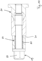
- a screw connection is cut in Figure 10 It has a screw 19 which is screwed into a threaded element 20 which is arranged on the base 12 or, for example, on the front wall 15.
- the screw 19 is inserted into a threaded element 20 which is arranged, for example, on the side wall 14 over a through opening (not shown) attached sleeve 21.
- the sleeve 21 has a spring portion 22 in which a spring 23 is provided.
- the screw 19 can be screwed into the threaded element 20 and thus lock the side wall 14 against the base 12 and/or the front wall 15.
- a drive system is provided that enables the side walls 14 to move against the base 12 and/or the end walls 15, or alternatively the floor 16.
- this can be a spindle system as a mechanical drive that, when driven, moves the side walls 14 around the pivot connection 13 in the double arrow direction G either away from the base 12 and the end walls 15 and the floor 16 or towards them.
- a hydraulic drive system is used, as explained in a second embodiment of the invention.
- a mechanical drive system it can be designed to be self-locking so that no screw connections are necessary to hold the side walls 14 against the floor 16 and the side walls 15.
- a locking element (not shown) can also be used to ensure holding by preventing reverse movement of the spindle drive.
- the central spindle can also be driven with a suitable tool, preferably the same tool with which the screws 19 are loosened and tightened.
- a rod element 24 is shown which can be moved by the central spindle in the double arrow direction H.
- the screw 19 is screwed into the threaded element 20 against the spring element 23, or when unscrewing the spring element 23 presses the screw 19 outwards so that it moves more easily out of the threaded element 20 when unscrewing.
- the formwork 10 has engagement openings 25 in the area of the screws 19, into which a torque transfer element 151 engages in order to create the tool 150 or to relieve the robot 140, which would otherwise have to transfer the torque accordingly.
- a second embodiment of the formwork 10 according to the invention is shown in the Fig. 11 to 15 shown.
- the formwork 10 has an interior space 17 for accommodating reinforcement, built-in components and concrete for producing the concrete segment 500. This is formed by a base 16 and the inner sides of the side walls 14 and the end walls 15. The base 16 is arranged on a base 12.
- the side walls 14 and the end walls 15 are fixedly arranged on the base via a pivot connection 13, 26.
- the pivot connection 13, 26 is connected to the side wall 14 or to the end wall 15 via a connecting element 27.
- the side walls 14, end walls 15 are pivoted about a pivot point 28 via the connecting elements 27, so that the side walls 14, end walls 15 are released from the base 16 and pivoted outwards, as shown in Figure 13 is shown.
- the pivoting takes place in the direction of the double arrow I.
- the base 12 has a lower frame 28 on which, among other things, a chassis is arranged, which here has, for example, wheels 29.
- the frame 28 can also be arranged on a transport element 112 in order to be moved along a production line, or the travel path of the production line itself has rollers on which the formwork 10 can be moved.
- base elements 31 and actuators 32 in the form of hydraulic cylinders are provided, which are firmly connected to the base element 31.
- a movement element 33 of the actuator 32 here a piston rod, is connected to the connecting element 27.
- the connecting element 27 is moved by a side wall 34 of the base 12 in the double arrow direction H.
- it is rotated about the pivot point 38 so that the side wall 14 is moved away from the interior space 17 or floor 16, so that the formwork 10 is opened in relation to the side walls 14.
- At least one actuator 35 here a hydraulic cylinder, is provided for opening the end walls 15, which are also connected to the base 12 via a connecting element 27 with a pivot connection 26, which has a pivot point 38.
- This can be arranged in the interior 30 in a similar way to the previously described actuator 32 in connection with the base element 31.
- the actuator 35 is arranged on the side wall 14 via a connection 36.
- the actuator 35 is arranged to be rotatable about a first axis 37 and at the same time rotatable about a second axis 39, so that when the end wall 15 is open, the actuator 35 can be pivoted together with the side wall 14 when it is opened.
- the actuator 35 has a movement element 41, here a piston rod that can be moved out of the actuator 35 in the double arrow direction H in order to pivot the front wall 15 about the pivot point 38 in the pivot connection 26 in the double arrow direction I.
- a corner 46 of the interior 17 is formed by the contact of an outer side 42 of a front wall 15 with an outer side 43 of a side wall 14.
- a male and a female engagement element 44, 45 are provided on the outer side 42 of the front wall 15 and correspondingly on the outer side 43 of the side wall 14, which engage with each other when the formwork is closed.
- the male engagement element 45 is preferably arranged on the front wall 15 and the female engagement element 44 on the side wall 14, so that the male engagement element 45 prevents movement of the side wall 14 when the front wall 15 is closed.
- the front wall 15 is pressed at its outer end 42 onto the side wall 14 at its outer end 43.
- the male engagement element 45 engages the female engagement element 44 and thereby locks in addition to pulling and holding the movement element 33 of the actuator 32, so that the side wall 14 cannot be detached from the base 16 as long as the front wall 15 is in contact with the base 16.
- the formwork 10 has two covers 50 which are attached to the base 12 and which, during the manufacturing process of the concrete segment 500, are either closed, as in Figure 11 shown, or opened, as in Figure 13 and 14 shown.
- the covers 50 are pivoted in the direction of the double arrow J between the closed position on the interior space 17 and the open position. They serve to close the formwork 10 or its interior space 17 upwards when the concrete is poured into the interior space 17.
- formwork 10 is known with partial covers, such as the covers 50 shown here in the second embodiment of the formwork 10 according to the invention, or without a cover 50, as is the case in the first embodiment not claimed.
- the uncovered areas are closed with a cover before the formwork 10 is filled with concrete, whereby open areas are still present through which the concrete is then poured into the interior space 17.
- These additional covers are attached before or in the concreting work station.
- covers 50 are provided on the formwork 10 that can be moved between an open and a closed position, they are closed in or before the concreting work station. After concreting, the covers are either removed (according to the first embodiment not claimed) or opened again in order to process the surface 520 of the raw concrete segment in a corresponding further work station/in a further work step. After this work step has been completed, the covers 50 are closed again.
- the formwork 10 with closed covers 50 are then fed to the hardening station.
- the covers 50 then remain closed within the hardening station.
- the covers 50 are opened.
- the side walls 14 and the end walls 15 are then also opened in the necessary order.
- the pre-hardened concrete segment 500 can then be removed.
- the formwork 10 is cleaned accordingly and prepared for the production of a new concrete segment 500, as previously described.
- the side walls 14, end walls 15 and cover 50 are either closed or remain open.
- the cover 50, end walls 15 and side walls 14 may then have to be opened again so that a complete cleaning can be carried out.
- the side walls 14 and the end walls 15 are then closed.
- the interior 17 is then equipped with the appropriate reinforcement and built-in parts.
- the formwork 10 is then prepared for concreting as described above.
- the lids 50 are provided with connecting elements 51 which are connected to the base 12 via a pivot connection 52.
- the pivot connection 52 is arranged so as to be rotatable on a projection element 53.
- An actuator 54 is provided which is connected to the base 12 parallel to the projection element 53.
- the connecting element 51 extends beyond the pivot connection 52.
- the movement element 55 of the actuator 54 then acts on this part of the connecting element 51.
- the lid 50 is pivoted in the direction of the double arrow J about the pivot point 38 located in the pivot connection 52.
- spring elements 56 are provided for support.
- the actuator 54 is a hydraulic cylinder.
- the moving element 55 represents the piston rod of the hydraulic cylinder.
- the actuator 54 also holds the cover 50 in the respective position.
- securing elements 57 are provided for securing the cover 50, which are provided with an actuator 58 that has a movement element 59.
- the movement element 59 is connected to a locking element 60 that can be moved between a locking position and a free position by extending and retracting the movement element 59, preferably pivotable here.
- engagement openings 61 are provided for locking, into which the locking element 60 engages for locking. Locking takes place, for example, during hardening.
- the actuators of the formwork 10 if these are designed as hydraulic cylinders, these are part of a hydraulic circuit.
- the actuators are referred to below as hydraulic cylinders.
- the hydraulic cylinders 32 for opening and closing the side walls and the hydraulic cylinders 35 for opening and closing the front walls are provided in such a way that the walls close when the hydraulic cylinder retracts.
- the hydraulic cylinders 54 of the cover 50 and the hydraulic cylinders 58 for actuating the locking elements 60 are arranged in such a way that the cover 50 and the locking element 60 close when the hydraulic cylinder retracts.
- the hydraulic circuit is connected to a hydraulic unit (not shown) via a connection.
- a hydraulic unit not shown
- the application of the holding force of the hydraulic cylinders after closing the side walls 14 and end walls 15 and after closing the covers 50 and the locking elements 60 must remain after the hydraulic circuit of the formwork 10 is disconnected from the drive unit.
- load holding valves (not shown) installed in the hydraulic circuit.
- the load holding valves ensure that the hydraulic fluid introduced into the hydraulic cylinder cannot flow back out of it after the hydraulic unit no longer supplies the hydraulic circuit with hydraulic fluid, which means that the pressure on the piston surface of the hydraulic cylinder remains constant.
- compensation elements are provided at the appropriate points in the hydraulic circuit. These can be, for example, diaphragm accumulators or dummy cylinders.
- the cylinders that are supplied with hydraulic fluid first determine the necessary control sequence.
- Switchable locking elements can be provided between the individual cylinders to control the sequence of the individual movements. These are preferably pressure sequence valves.
Landscapes
- Engineering & Computer Science (AREA)
- Mechanical Engineering (AREA)
- Chemical & Material Sciences (AREA)
- Ceramic Engineering (AREA)
- Manufacturing & Machinery (AREA)
- Structural Engineering (AREA)
- Robotics (AREA)
- Architecture (AREA)
- Mining & Mineral Resources (AREA)
- Automation & Control Theory (AREA)
- Civil Engineering (AREA)
- Life Sciences & Earth Sciences (AREA)
- General Life Sciences & Earth Sciences (AREA)
- Geochemistry & Mineralogy (AREA)
- Geology (AREA)
- Lining And Supports For Tunnels (AREA)
- Moulds, Cores, Or Mandrels (AREA)
- Devices For Post-Treatments, Processing, Supply, Discharge, And Other Processes (AREA)
- On-Site Construction Work That Accompanies The Preparation And Application Of Concrete (AREA)
Description
- Die Erfindung betrifft eine Schalung zur Herstellung eines Betontübbings eines Tunnelausbausystems nach dem Oberbegriff des Anspruchs 1.
- Zur Betontübbingproduktion werden die einzelnen Arbeitsschritte zur Herstellung eines Betontübbings manuell durchgeführt. Neben den dabei anfallenden Arbeitskosten ist die auszuführende Arbeit monoton und für die Mitarbeiter anstrengend. Weiterhin werden die Tätigkeiten mit schweren Gegenständen durchgeführt, sodass Verletzungsgefahr gegeben ist. Trotz der wiederkehrenden Tätigkeiten ist es gleichzeitig notwendig, die Arbeiten mit sehr hoher Präzision durchzuführen.
- Dieses betrifft insbesondere den Einsatz der Schalungen. Diese müssen an verschiedenen Arbeitsstationen der Produktionsline teilweise oder vollständig geöffnet oder geschlossen werden. Dieses erfolgt dabei manuell und ist daher arbeits- und zeitintensiv. Weiterhin muss erhebliche Sorgfalt insbesondere beim Schließen aufgewendet werden, damit die Schalungen dicht sind und der eingebrachte Beton beim Betonieren nicht ausläuft.
-
JP 2001 047421 A - Aufgabe der Erfindung ist daher, zumindest Teilaspekte der zuvor genannten Probleme zu reduzieren.
- Die Aufgabe wird durch eine Schalung nach Anspruch 1 gelöst.
- Hierdurch wird es auf einfache Weise möglich, das Öffnen und Schließen zu vereinfachen und gleichzeitig auf einfache Weise das Halten sicherzustellen, so dass die Schalung sicher geschlossen bleibt.
- Eine weitere Lehre der Erfindung sieht vor, dass sich wenigstens zwei Wände an einem ihrer beiden äußeren Endbereiche mit ihren kurzen Seiten in geschlossener Position berühren und dabei eine Ecke der Betonwanne ausformen. Dabei ist vorteilhaft, dass an einer der zwei Wände im äußeren Endbereich ein männliches Eingriffelement und an der anderen Wand im äußeren Endbereich ein weibliches Eingriffelement vorgesehen ist, die in geschlossener Position der zwei Wände ineinandergreifen. Hierdurch kann auf einfache Weise der Schluss der Ecke sichergestellt werden.
- Dabei ist weiterhin vorteilhaft, dass die zwei Wände in ihren äußeren Endbereichen miteinander mittels wenigstens einer Schraubverbindung oder einer Klemmverbindung miteinander verbunden werden, wobei die Schraubverbindung oder Klemmverbindung bevorzugt zur Positionssicherung dient, und/oder wobei die Schraubverbindung eine Schraube mit einem entlang wenigstens eines Teils der Schraube angeordneten Federelement aufweist. Dieses stellt insbesondere eine einfache Zusatzsicherung dar, bei der auf einfache Weise die Positionierung gewährleistet bleibt.
- Eine weitere Lehre der Erfindung sieht vor, dass die Klemmverbindung ein Arretierungselement aufweist, das an einem der Wandelemente angeordnet ist und verschwenkbar zwischen einer offenen und einer geschlossenen Position mit wenigstens einem Aktuator, beispielsweise einem Hydraulikzylinder oder einem Spindelsystem, bewegbar ist. Dabei ist vorteilhaft, dass der Aktuator mit dem nachfolgend beschriebenen Antriebssystem verbunden ist. Hierdurch kann auf einfache Weise eine Sicherung bereitgestellt werden.
- Eine weitere Lehre der Erfindung sieht vor, dass die wenigstens eine Wand zum Bewegen zwischen der offenen und der geschlossenen Position mit wenigstens zwei Aktuatoren des Antriebssystems verbunden ist. Hierdurch lässt sich auf einfache Weise die notwendigen Haltekräfte aufbringen und verteilen.
- Eine weitere Lehre der Erfindung sieht vor, dass das wenigstens eine Wandelement zwei äußere Endbereiche aufweist, und dass pro Endbereich zum Bewegen und Halten des Wandelements wenigstens ein Aktuator vorgesehen ist. Es hat sich gezeigt, dass hierdurch auf besonders einfache Weise ein dichter Verschluss auch bei Befüllung der Schalung mit Beton und evtl. Verformung der Seitenwände hierdurch gewährleistet werden kann.
- Eine weitere Lehre der Erfindung sieht vor, dass das Antriebssystem an einer Arbeitsstation mit einem externen Antrieb zum Antreiben des Antriebssystems verbindbar ist. Hierdurch kann der Aufbau der Schalung möglichst einfach ausfallen, da auf einen Antrieb in der Schalung verzichtet werden kann.
- Gemäß der Erfindung handelt es sich bei dem Antriebssystem um ein Hydrauliksystem mit wenigstens einem Hydraulikkreislauf, wobei das Antriebssystem wenigstens einen Hydraulikzylinder als Aktuator aufweist, der mit dem Hydraulikkreislauf verbunden ist. Hierdurch kann auf einfache Weise sowohl das Bewegen als auch das Halten mit hinreichenden Kräften bereitgestellt werden.
- Dabei ist vorteilhaft, dass der Hydraulikkreislauf ein Sperrelement zum Halten des Drucks im Hydraulikkreislauf aufweist, wobei es sich bevorzugt um ein Lastaufnahmeventil handelt. Dabei ist weiterhin vorteilhaft, dass der Hydraulikkreislauf ein Element zum Ausgleich einer Druckänderung und/oder einer Volumenänderung im Hydraulikkreislauf aufweist, wobei es sich bevorzugt um einen Blindzylinder oder um einen Membranspeicher handelt. Dabei ist weiterhin vorteilhaft, dass der Hydraulikkreislauf wenigstens ein Anschlusselement zum lösbaren Anschließen des Hydraulikkreislaufs an ein Hydraulikaggregat als externen Antrieb des Antriebssystems an einer Arbeitsstation aufweist. Weiterhin ist vorteilhaft vorgesehen, dass die einzelnen Hydraulikzylinder mittels Druckfolgeventile verbunden sind.
- Dadurch kann auf einfache Weise eine Ablaufsteuerung der einzelnen Schritte des Öffnens und/ioder Schließens der Schalung erreicht werden. Durch wenigstens eines der zuvor genannten Elemente lässt sichein erfindungsgemäßer Hydraulikkreislauf auf einfache Weise bereitstellen.
- Ein weiterer nicht beanspruchter Aspekt sieht vor, dass es sich bei dem Antriebssystem um einen mechanischen Antrieb als Aktuator, bevorzugt um einen Spindelantrieb, handelt. Dabei ist vorteilhaft, dass der mechanische Antrieb selbsthemmend ausgelegt ist oder mit einem Sperrelement versehen ist. Dabei ist weiterhin vorteilhaft, dass der mechanische Antrieb ein Verbindungselement zum lösbaren Verbinden mit einem externen Rotationsantrieb, beispielsweise einem Drehmomentenschrauber, als externen Antrieb des Antriebssystems an einer Arbeitsstation aufweist.
- Gemäß der Erfindung ist wenigstens ein Deckelelement schwenkbar an der Schalung vorgesehen, der auf der Oberseite der Betonwanne anordbar ist und auf dieser die Oberseite wenigstens teilweise überdeckt. Das Deckelelement ist mit wenigstens einem Aktuator, der ein Hydraulikzylinder ist, zwischen einer offenen und einer geschlossenen Position verschwenkbar, der das Deckelement bevorzugt in der jeweiligen Position hält. Dabei ist weiterhin vorteilhaft, dass der Aktuator mit dem zuvor beschriebenen Antriebssystem verbunden ist.
- Eine weitere Lehre der Erfindung sieht vor, dass das Deckelelement ein Arretierungselement aufweist, das das Deckelelement in geschlossener Position gegenüber der Schalung arretiert.
- Nachfolgend wird die Erfindung anhand von Ausführungsbeispielen in Verbindung mit einer Zeichnung näher erläutert. Dabei zeigen:
- Figur 1
- eine Draufsicht auf eine Produktionsanlage
- Figur 2
- eine räumliche Ansicht zu
Figur 1 , - Figur 3
- eine Seitenansicht zu
Figur 1 , - Figur 4
- eine weitere räumliche Ansicht zu
Figur 1 , - Figur 5
- eine räumliche Ausschnittsvergrößerung zu
Figur 3 , - Figur 6
- eine räumliche Ausschnittsansicht zu
Figur 5 , - Figur 7
- eine räumliche Ansicht einer ersten Ausführungsform einer nicht beanspruchtenSchalung,
- Figur 8
- eine vergrößerte Ausschnittsansicht zu
Figur 7 , - Figur 9
- eine räumliche Ansicht einer geöffneten ersten Ausführungsform der Schalung,
- Figur 10
- eine Schnittansicht durch ein Befestigungselement zu
Figur 7 , - Figur 11
- eine räumliche Ansicht einer zweiten Ausführungsform einer erfindungsgemäßen Schalung in geschlossenem Zustand,
- Figur 11a
- eine vergrößerte Ausschnittsansicht zu
Figur 11 , - Figur 12
- eine Unteransicht zu
Figur 11 , - Figur 12a
- eine vergrößerte Ausschnittsansicht zu
Figur 12 , - Figur 12b
- eine weitere vergrößerte Ausschnittsansicht zu
Figur 12 , - Figur 13
- eine räumliche Ansicht einer zweiten Ausführungsform einer erfindungsgemäßen Schalung in geöffnetem Zustand,
- Figur 13a
- eine vergrößerte Ausschnittsansicht zu
Figur 13 , - Figur 13b
- eine weitere vergrößerte Ausschnittsansicht zu
Figur 13 , - Figur 14
- eine räumliche Seitenansicht auf die Seitenwand der erfindungsgemäßen Schalung zu den
Figuren 11 und13 , und - Figur 15
- eine räumliche Seitenansicht auf die Stirnwand der erfindungsgemäßen Schalung.
-
Figur 1 bis 4 zeigen eine Produktionsanlage 100 für Betontübbinge 500 bei der eine erfindungsgemäße Schalung 10 zu Anwendung kommt. Die Produktionsanlage 100 ist dabei beispielsweise als Umlaufanlage für die Schalungen 10 ausgeführt. Alternativ kann die erfindungsgemäße Schalung auch bei einer Standanlage (nicht dargestellt) zum Einsatz kommen, bei der die Schalungen für die Herstellungsschritte vor dem Einbringen in eine Härteanlage zum beschleunigten Ersthärten des Betontübbings 500, sofern dieses Härten notwendig ist, erfolgen, an einem Ort verbleiben. - Die hier beispielhaft gezeigte Umlaufanlage besteht aus mindestens einer Produktionslinie 200 und einem Härtetunnel 300. Der Härtetunnel 300 weist dabei beispielsweise mindestens eine Härtelinie 310, in
Figur 1 dargestellt drei Härtelinie 310, auf. Die Produktionslinie 200 und der Härtetunnel 300 bzw. dessen Härtelinien 310 sind mit einem Querförderer 400 verbunden. - Die Produktionsanlage 100 weist beispielsweise einen Transportweg 110 auf. Der Transportweg 110 weist beispielsweise eine Fahrbahn 111 auf, auf der die Schalung 10 verfahrbar ist. Dafür weist die Schalung entweder ein eigenes Transportmittel beispielsweise in Form von Rädern auf, oder die Schalung 10 ist auf einem separaten Transportmittel 112 angeordnet. Die Schalung 10/die Transportmittel 112 bewegen sich entlang des Transportwegs 110 in Pfeilrichtung A durch die Produktionslinie 200, beispielsweise über ein Antreiben der Räder oder über einen nicht dargestellten Mitnehmer.
- Nach Durchlaufen der Produktionslinie 200 werden die Schalungen 10 von einem Querförderer 400 in Pfeilrichtung B den Härtelinien 310 des Härtetunnels 300 zugeführt. Auch der Querförderer 400 weist eine Fahrbahn 111 auf, auf der die Schalung 10/die Transportmittel 112 bewegt werden, beispielsweise über ein Antreiben der Räder oder über einen nicht dargestellten Mitnehmer. Gleiches gilt auch für die Härtelinien 310 des Härtetunnels 300.
- Nach Durchlaufen des Härtetunnels 300 in Pfeilrichtung C werden die Transportmittel 112 mittels des Querförderer 400 in Pfeilrichtung D der Produktionslinie 200 wieder zugeführt. Der Umlauf ist dann abgeschlossen.
- In Pfeilrichtung A, in
Figur 1 von links nach rechts gesehen, weist die Produktionslinie 200 hier beispielhaft sechs Arbeitsstationen 210 - 260 auf. - An der ersten Arbeitsstation 210 wird die Schalung 10 wie nachfolgend erläutert, geöffnet.
- An der zweiten Arbeitsstation 220 wird der fertige Tübbing 500 mittels eines Hebeelements (nicht dargestellt) aus der Schalung 10 entnommen. Dieses kann alternativ auch bereits an der ersten Arbeitsstation 210 erfolgen und die Arbeitsstation 220 kann dann entfallen.
- An der dritten Arbeitsstation 230 wird die bevorzugt geöffnete Schalung 10 gereinigt und für die Aufnahme von Einbauelemente sowie die Betonierung vorbereitet. Hierzu wird beispielsweise ein Trennmittel (Schalungsöl) auf alle Flächen und Teile der Schalung aufgebracht, die in den Kontakt mit dem Beton des herzustellenden Tübbings 500 kommen und nicht Bestandteil des Tübbings 500 werden sollen.
- An der vierten Arbeitsstation 240 wird die Schalung 10 mit den Einbauteilen bestückt, die Bestandteil des fertigen Tübbings 500 sind. Hierbei handelt es sich beispielsweise um eine Bewehrung 510, Elektrodübel (nicht dargestellt), einen Schutzliner oder dergleichen.
- Nach Einbringen der Einbauteile, die alternativ auch vollständig oder teilweise an der dritten Arbeitsstation 230 nach Abschluss der Reinigung und der Vorbereitung in die Schalung 10 eingebracht werden können, wird die Schalung 10 mit den eingebrachten Komponenten kontrolliert, um zu gewährleisten, dass die Schalung 10 korrekt zusammengebaut ist und die Einbauteile des Tübbings 500 korrekt angeordnet sind.
- Das Bestücken der Schalung 10 mit den Einbauteilen kann auch aufgeteilt in den Arbeitsstationen 230, 240 erfolgen.
- In der fünften Arbeitsstation 250 werden, soweit nicht vorher bereits geschehen und nach einem nicht beanspruchten Aspekt, die evtl.
- vorgesehenen Deckel (nicht dargestellt) der Schalung montiert. Alternativ und gemäß der Erfindung sind die Deckel beweglich an der Schalung 10 angeordnet und werden vor dem Eintritt in die fünfte Arbeitsstation 250 oder in der fünften Arbeitsstation 250 geschlossen.
- Diese schließen wird nachfolgend erläutert. Der in die Schalung 10 einzubringende Beton nach notwendiger Mixtur vorbereitet und in notwendiger Menge und in die Schalung 10 in der fünften Arbeitsstation 250 eingebracht. Anschließend wird der eingebrachte Beton in bekannter Weise beispielsweise durch Rütteln verdichtet. Alternativ erfolgt das Einbringen und Verdichten in mehreren Schritten.
- Vor oder in der sechsten Arbeitsstation 260 wird der Deckel bzw. werden die Deckel der Schalung 10 entfernt/geöffnet und die Betonoberfläche 520 des Tübbings wird behandelt, beispielsweise geglättet. Nach dem Behandeln/Glätten werden die Deckel der Schalung 10 wieder geschlossen, wie nachfolgend beschrieben wird.
- Die Produktionslinie 200 wird dann nach der sechsten Arbeitsstation 260 in diesem Beispiel verlassen, in dem die Schalung 10/das Transportmittel 112 mit der Schalung 10 und dem in der Schalung 10 vollständig hergestellten rohen Tübbing 500 an den Querförderer 400 übergeben wird.
- Die Anzahl der Arbeitsstationen ist hier nur beispielhaft zu sehen. Es ist einem Fachmann ohne weiteres möglich, die Anzahl der Arbeitsstationen durch Zusammenfassen oder Entkoppeln von einzelnen Arbeitsschritten entsprechend den Notwendigkeiten anzupassen.
- Eine erste nicht beanspruchte Ausführungsform der Schalung 10 (siehe
Fig. 5 bis 10 ) ist beispielsweise über einen Sockel 11 des Transportmittels 112 angeordnet. Die Schalung selbst weist eine Basis 12 auf, mit der sie auf dem Sockel 11 anordbar ist. Über der Basis ist ein Innenraum 17 als eine Betonwanne vorgesehen, der aus einem Boden 16 und Innenwänden der Stirnwände 15 und Seitenwände 14 gebildet ist. In diese Betonwanne bzw. in diesen Innenraum 17 werden die Einbauteile und der Beton eingebracht. - Über Schwenkverbindungen 13 ist die Basis 12 in dieser Ausführungsform nicht beschränkend mit zwei Seitenwänden 14 der Schalung 10 verschwenkbar verbunden. Weiterhin weist die Schalung 10 zwei Stirnwände 15 auf. In den in den
Figuren 5 bis 10 gezeigten Schalungen 10 sind die Stirnwände 15 fest mit der Basis 12 verbunden. Es ist hier genauso möglich, dass auch die Stirnwände 15 über Gelenksverbindungen mit der Basis 12 fest schwenkbar verbunden sind. - In der in den
Figuren 5 bis 10 gezeigten nicht beanspruchten Ausführungsform werden die Seitenwände 14 über Schraubverbindungen mit der Basis 12 und den Stirnwänden 15 haltend verbunden. Eine solche Schraubverbindung ist geschnitten inFigur 10 dargestellt. Sie weist eine Schraube 19 auf, die in ein Gewindeelement 20, die an der Basis 12 oder beispielsweise an der Stirnwand 15 angeordnet ist, eingeschraubt wird. Die Schraube 19 ist eingesteckt in eine beispielsweise an der Seitenwand 14 über einer durchgängigen Öffnung (nicht dargestellt) angebrachten Hülse 21. Die Hülse 21 weist dabei einen Federabschnitt 22 auf, in dem eine Feder 23 vorgesehen ist. - Sind das Gewindeelement 20 und die Hülse 21 fluchtend übereinander angeordnet, wenn beispielsweise die Seitenwand 14 gegen die Stirnwand 15 und die Basis 12 angeordnet ist, kann die Schraube 19 in das Gewindeelement 20 eingeschraubt werden und damit die Seitenwand 14 gegen die Basis 12 und /oder die Stirnwand 15 arretieren.
- Dafür ist ein Antriebssystem vorgesehen, dass das Bewegen der Seitenwände 14 gegen die Basis 12 und/oder die Stirnwände 15 alternativ auch den Boden 16 ermöglicht. Beispielsweise kann es sich hierbei um ein Spindelsystem als mechanischen Antrieb handeln, dass, wenn es angetrieben wird, die Seitenwände 14 um die Schwenkverbindung 13 in Doppelpfeilrichtung G entweder von der Basis 12 und den Stirnwänden 15 und dem Boden 16 weg oder zu diesen hinbewegt werden. Alternativ und gemäß der Erfindung wird ein hydraulisches Antriebssystem eingesetzt, wie es in einem zweiten erfindungsgemäßen Ausführungsbeispiel erläutert wird.
- Wird ein mechanisches Antriebssystem verwendet, so kann es so ausgelegt werden, dass es selbsthemmend ist, so dass keine Schraubverbindungen notwendig sind, um die Seitenwände 14 gegen den Boden 16 und die Seitenwände 15 zu halten. Alternativ oder zusätzlich kann auch ein Sperrelement (nicht dargestellt) verwendet werden, um ein Halten zu gewährleisten, indem eine Rückbewegung des Spindelantriebs verhindert wird.
- In einer bevorzugten Ausführungsform lässt sich die Zentralspindel auch mit einem geeigneten Werkzeug, vorzugsweise dem gleichen Werkzeug, mit dem die Schrauben 19 gelöst und festgezogen werden, antreiben. In den
Figuren 7 ,8 und9 ist ein Stabelement 24 gezeigt, dass von der Zentralspindel in Doppelpfeilrichtung H bewegbar ist. - Das Einschrauben der Schraube 19 in das Gewindeelement 20 erfolgt gegen das Federelement 23, bzw. beim Ausschrauben drückt das Federelement 23 die Schraube 19 nach außen, sodass sich diese leichter beim Ausschrauben aus dem Gewindeelement 20 heraus bewegt.
- Hierdurch ist es auf einfache Weise möglich, dass beim Einsatz eines Drehmomentschraubers als Werkzeug 150 am Roboter 140 dieser die Schraube 19 aus dem Gewindeelement 20 herausschrauben kann, sodass sich diese sicher löst, ohne dass der Drehmomentschrauber eine Zugkraft auf die Schraube 19 ausüben muss.
- Weiterhin weist die Schalung 10 im Bereich der Schrauben 19 Eingriffsöffnungen 25 auf, in die ein Drehmomentabtragelement 151 eingreift, um das Werkzeug 150 entsteht bzw. den Roboter 140 zu entlasten, die sonst das Drehmoment entsprechend abtragen müssten.
- Eine zweite erfindungsgemäße Ausführungsform der Schalung 10 ist in den
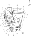
Fig. 11 bis 15 dargestellt. - Die Schalung 10 weist einen Innenraum 17 zur Aufnahme von Bewehrung, Einbauteilen und Beton zur Herstellung des Betontübbings 500 auf. Dieser wird gebildet durch einen Boden 16 sowie die Innenseiten der Seitenwände 14 und der Stirnwände 15. Der Boden 16 ist dabei auf einer Basis 12 angeordnet.
- Die Seitenwände 14 und die Stirnwände 15 sind fest an der Basis über eine Schwenkverbindung 13, 26 schwenkbar angeordnet. Die Schwenkverbindung 13, 26 ist jeweils über ein Verbindungselement 27 mit der Seitenwand 14 bzw. mit der Stirnwand 15 verbunden. Über die Verbindungselemente 27 werden die Seitenwände 14, Stirnwände 15 um einen Drehpunkt 28 verschwenkt, sodass sich die Seitenwände 14, Stirnwände 15 vom Boden 16 lösen und nach außen verschwenkt werden, wie dieses in
Figur 13 gezeigt ist. Das Verschwenken erfolgt in Doppelpfeilrichtung I. - Die Basis 12 weist einen unteren Rahmen 28 auf, an dem unter anderem beispielsweise ein Fahrwerk angeordnet ist, das hier beispielhaft Räder 29 aufweist. Alternativ kann der Rahmen 28 auch auf einem Transportelement 112 angeordnet sein, um entlang einer Produktionslinie verfahren zu werden, oder der Fahrweg der Produktionslinie selber weist Rollen auf, auf denen die Schalungen 10 verfahrbar sind.
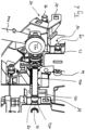
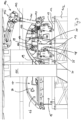
- In einem Innenraum 30 der Basis 12 sind Basiselemente 31 und Aktuatoren 32, in Form von Hydraulikzylindern, vorgesehen, die mit dem Basiselement 31 fest verbunden sind. Ein Bewegungselement 33 des Aktuators 32, hier eine Kolbenstange, ist mit dem Verbindungselement 27 verbunden. Durch lineares Bewegen des Bewegungselementes 33 des Aktuators 32 wird das Verbindungselement 27 von einer Seitenwand 34 der Basis 12 in Doppelpfeilrichtung H bewegt. Gleichzeitig wird es um den Drehpunkt 38 gedreht, sodass die Seitenwand 14 vom Innenraum 17 bzw. Boden 16 wegbewegt wird, sodass die Schalung 10 in Bezug auf die Seitenwände 14 geöffnet wird.
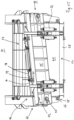
- Zum Öffnen der Stirnwände 15, die ebenfalls über ein Verbindungselement 27 mit einer Schwenkverbindung 26, die einen Drehpunkt 38 aufweist, mit der Basis 12 verbunden ist, ist wenigstens ein Aktuator 35, hier ein Hydraulikzylinder, vorgesehen. Dieser kann ähnlich zu dem zuvor beschriebenen Aktuator 32 in Verbindung mit dem Basiselement 31 im Innenraum 30 angeordnet sein. Alternativ ist der Aktuator 35 über eine Verbindung 36 an der Seitenwand 14 angeordnet. In der Verbindung 36 ist der Aktuator 35 um eine erste Achse 37 drehbar und gleichzeitig um eine zweite Achse 39 drehbar angeordnet, sodass der Aktuator 35, wenn die Stirnwand 15 geöffnet ist, zusammen mit der Seitenwand 14 beim Öffnen derselben verschwenkt werden kann.
- Gleiches gilt auch für die Verbindung 40, mit der der Aktuator 35 mit der Stirnwand 15 verbunden ist. Der Aktuator 35 weist ein Bewegungselement 41 auf, hier eine Kolbenstange die aus dem Aktuator 35 in Doppelpfeilrichtung H heraus bewegt werden kann, um die Stirnwand 15 um den Drehpunkt 38 in der Schwenkverbindung 26 in Doppelpfeilrichtung I zu verschwenken. Eine Ecke 46 des Innenraums 17 wird durch das Berühren einer Außenseite 42 einer Stirnwand 15 mit einer Außenseite 43 einer Seitenwand 14 gebildet. Zusätzlich sind an der Außenseite 42 der Stirnwand 15 und dazu entsprechend passend an der Außenseite 43 der Seitenwand 14 ein männliches und ein weibliches Eingriffelement 44, 45 vorgesehen, die im geschlossenen Zustand der Schalung ineinandergreifen. Hier ist bevorzugt das männliche Eingriffelement 45 an der Stirnwand 15 und das weibliche Eingriffelement 44 an der Seitenwand 14 angeordnet, sodass das männliche Eingriffelement 45 ein Bewegen der Seitenwand 14 im geschlossenen Zustand der Stirnwand 15 verhindert. Durch Anziehen und Halten des Bewegungselements 41 des Aktivators 35 wird die Stirnwand 15 an ihrem äußeren Ende 42 auf die Seitenwand 14 an ihrem äußeren Ende 43 angepresst. Gleichzeitig greift das männliche Eingriffelement 45 in das weibliche Eingriffelement 44 und sperrt dadurch zusätzlich zum Anziehen und Halten des Bewegungselements 33 des Aktuators 32, sodass die Seitenwand 14 nicht vom Boden 16 gelöst werden kann, solange die Stirnwand 15 am Boden 16 anliegt. Durch das Anziehen und Halten des Bewegungselements 41 des Aktivators 35 am äußeren Ende 42 wird gleichzeitig bevorzugt in Verbindung mit den Eingriffelementen 44, 45, ein Öffnen der Ecken 46, gebildet zwischen den Seitenwänden 14 und den Stirnwänden 15, effektiv und einfach vermieden.
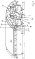
- Ein Ablösen der Seitenwände 14 und der Stirnwände 15 vom Boden 16 beispielsweise durch Lastverformung durch den eingebrachten Beton wird durch das Verteilen der Schwenkverbindungen 13, 26 entlang der Seitenwände 34, 47 der Basis 12 verhindert. Weiterhin weist die Schalung 10 zwei Deckel 50 auf, die an der Basis 12 angebracht sind und während des Herstellungsprozesses des Betontübbings 500 entweder geschlossen, wie in
Figur 11 dargestellt, oder geöffnet, wie inFigur 13 und14 dargestellt, sind. - Die Deckel 50 werden in Doppelpfeilrichtung J zwischen der geschlossenen Position auf dem Innenraum 17 und der geöffneten Position verschwenkt. Sie dienen dazu, die Schalung 10 bzw. deren Innenraum 17 nach oben zu schließen, wenn der Beton in den Innenraum 17 eingefüllt wird. Bei der Tübbingherstellung sind Schalungen 10 bekannt mit Teildeckeln, wie die Deckel 50 in der zweiten Ausführungsform der erfindungsgemäßen Schalung 10 hier gezeigt sind, oder auch ohne Deckel 50, wie dieses in der ersten nicht beanspruchten Ausführungsform beispielhaft der Fall ist. Die nicht überdeckten Bereiche werden vor dem Befüllen der Schalung 10 mit Beton mit einem Deckel geschlossen, wobei noch offene Bereiche vorhanden sind, durch die dann der Beton in den Innenraum 17 eingefüllt wird. Das Anbringen dieser zusätzlichen Deckel erfolgt vor oder in der Betonierarbeitstation.
- Sind wie hier im zweiten Ausführungsbeispiel Deckel 50 an der Schalung 10 vorgesehen, die zwischen einer geöffneten und einer geschlossenen Position bewegt werden, so werden diese in oder vor der Betonierarbeitstation geschlossen. Nach dem Betonieren werden die Deckel entweder entfernt (nach der ersten nicht beanspruchten Ausführungsform) oder wieder geöffnet, um die Oberfläche 520 des rohen Betontübbings in einer entsprechenden weitern Arbeitsstation/in einem weiteren Arbeitsschritt zu bearbeiten. Nach Abschluss dieses Arbeitsschritts werden die Deckel 50 wieder geschlossen. Anschließend werden die Schalungen 10 mit geschlossenen Deckeln 50 der Härtestation zugeführt. Innerhalb der Härtestation bleiben die Deckel 50 dann entsprechend geschlossen. Nachdem die Härtung abgeschlossen ist, werden die Deckel 50 geöffnet. Anschließend werden auch die Seitenwände 14 und die Stirnwände 15 in notwendiger Reihenfolge geöffnet. Hiernach ist der vorgehärtete Betontübbing 500 entnehmbar.
- Nach der Entnahme des Betontübbings 500 wird die Schalung 10 entsprechend gereinigt und für die Herstellung eines neuen Betontübbings 500 vorbereitet, wie zuvor beschrieben. Je nach Möglichkeiten des Transports werden die Seitenwände 14, Stirnwände 15 und Deckel 50 entweder geschlossen oder bleiben im geöffneten Zustand. In der Reinigungsstation müssen dann die Deckel 50, Stirnwände 15 und Seitenwände 14 ggf. wieder geöffnet werden, damit eine vollständige Reinigung vollzogen werden kann. Im Anschluss an die Reinigung werden dann die Seitenwände 14 und die Stirnwände 15 geschlossen. Der Innenraum 17 wird dann mit entsprechender Bewehrung und Einbauteilen bestückt. Ist dieses abgeschlossen, wird anschließend wie zuvor beschrieben die Schalung 10 auf das Betonieren vorbereitet. Die Deckel 50 sind mit Verbindungselementen 51 versehen, die über eine Schwenkverbindung 52 mit der Basis 12 verbunden sind. Die Schwenkverbindung 52 ist dabei an einem Vorsprungelement 53 drehbar angeordnet. Vorgesehen ist ein Aktuator 54, der parallel zum Vorsprungelement 53 mit der Basis 12 verbunden ist. Das Verbindungselement 51 erstreckt sich über die Schwenkverbindung 52 hinaus. An diesem Teil des Verbindungselement 51 greift dann das Bewegungselement 55 des Aktuators 54 an. Durch Ein- und Ausfahrt des Bewegungselements 55 wird der Deckel 50 in Doppelpfeilrichtung J um den in der Schwenkverbindung 52 befindlichen Drehpunkt 38 verschwenkt. Um ein besseres Öffnen und Schließen bzw. Durchführen der Schwenkbewegung in Pfeilrichtung J zu gewährleisten, sind Federelemente 56 zur Unterstützung vorgesehen.
- Bei dem Aktuator 54 handelt es sich um einen Hydraulikzylinder. Das Bewegungselement 55 stellt dabei die Kolbenstange des Hydraulikzylinders dar. Der Aktuator 54 bewirkt neben dem Öffnen und Schließen auch das Halten des Deckels 50 in der jeweiligen Position.
- Zusätzlich sind zur Sicherung am Deckel 50 Sicherungselemente 57 vorgesehen, die mit einem Aktuator 58 versehen sind, der ein Bewegungselement 59 aufweist. Das Bewegungselement 59 ist verbunden mit einem Sperrelement 60, dass über das Ein- und Ausfahren des Bewegungselements 59 zwischen einer Verriegelungspositionen einer freien Position bewegbar ist, hier bevorzugt verschwenkbar. An den Seitenwänden 14 bzw. Stirnwänden 15 sind zum Verriegeln Eingrifföffnungen 61 vorgesehen, in die das Sperrelement 60 zum Verriegeln eingreift. Das Verriegeln erfolgt beispielsweise während des Härtens.
- Zur Steuerung der Aktuatoren der Schalung 10, wenn diese als Hydraulikzylinder ausgeführt sind, sind diese Teil eines Hydraulikkreislaufes. Die Aktoren werden nachfolgend als Hydraulikzylinder bezeichnet. Hierbei sind die Hydraulikzylinder 32 zum Öffnen und Schließen der Seitenwände und die Hydraulikzylinder 35 zum Öffnen und Schließen der Stirnwände so vorgesehen, dass die Wände schließen, wenn der Hydraulikzylinder einfährt. Die Hydraulikzylinder 54 des Deckels 50 und die Hydraulikzylinder 58 zum Betätigen der Sperrelemente 60 sind dabei so angeordnet, dass der Deckel 50 und das Sperrelement 60 schließen, wenn der Hydraulikzylinder einfährt.
- An den jeweiligen Arbeitsstationen, an denen die Hydraulikzylinder betätigt werden müssen, wird über einen Anschluss der Hydraulikkreislauf an ein nicht dargestelltes Hydraulikaggregat angeschlossen. Das Aufbringen der haltenden Kraft der Hydraulikzylinder nach dem Verschließen der Seitenwände 14 und Stirnwände 15 sowie nach dem Verschließen der Deckel 50 und der Sperrelemente 60 muss nach Abkoppeln des Hydraulikkreislauf der Schalung 10 vom Antriebsaggregat bestehen bleiben.
- Das Halten der notwendigen Verschlusskräfte erfolgt durch in den Hydraulikkreislauf eingebrachte Lasthalteventile (nicht dargestellt). Die Lasthalteventile bewirken, dass die in den Hydraulikzylinder eingebrachte Hydraulikflüssigkeit nicht aus diesem wieder zurückfließen kann, nachdem das Hydraulikaggregat den Hydraulikkreislauf nicht mehr mit Hydraulikflüssigkeit beaufschlagt, wodurch der Druck auf die Kolbenfläche des Hydraulikzylinders konstant bleibt.
- Um Druckschwankungen/Volumenänderungen im Hydraulikkreislauf beispielsweise aufgrund von Temperaturänderungen in der Härteanlage entgegenzuwirken, sind an entsprechenden Stellen im Hydraulikkreislauf Ausgleichelemente vorgesehen. Hierbei kann es sich beispielsweise um Membranspeicher oder Blindzylinder handeln.
- Welche Zylinder zuerst mit Hydraulikflüssigkeit beaufschlagt werden, ergibt dabei die notwendige Steuerungsreihenfolge. Zwischen den einzelnen Zylindern können zur Abfolge der Steuerung der einzelnen Bewegungen schaltbare Sperrelemente vorgesehen sein. Bevorzugt handelt es sich hierbei um Druckfolgeventile.
Claims (12)
- Schalung (10) zur Herstellung eines Betontübbings (500) eines Tunnelausbausystems, mit einer Betonwanne zur Aufnahme einer zur Herstellung des Tübbings notwendigen Betonmenge und falls erforderlich zur Aufnahme der vorgesehenen Bewehrung des Betontübbings (500), wobei die Betonwanne wenigstens einen Boden (16) und an dem Boden (16) der Form nach angepassten Wände (14, 15) aufweist, wobei wenigstens ein Wand (14, 15) von dem Boden (16) lösbar und gegenüber dem Boden zwischen einer geschlossenen Position und einer geöffneten Position verschwenkbar angeordnet ist, wobei die Schalung (10) wenigstens ein Antriebssystem zum Verschwenken der wenigstens einen Wand (14, 15) zwischen der offenen und der geschlossenen Position und zum Halten in der jeweiligen Position aufweist, und dass das Antriebssystem wenigstens einen ersten Aktuator (32, 35) für das Verschwenken der wenigstens einen Wand (14, 15) zwischen der offenen und der geschlossenen Position aufweist, wobei es sich bei dem Antriebssystem um ein Hydrauliksystem mit wenigstens einem Hydraulikkreislauf handelt, wobei das Antriebssystem wenigstens einen Hydraulikzylinder als wenigstens einen ersten Aktuator (32, 35) aufweist, der mit dem Hydraulikkreislauf verbunden ist, dadurch gekennzeichnet, dass an der Schalung (10) schwenkbar wenigstens ein Deckelelement (50) vorgesehen ist, das auf der Oberseite der Betonwanne anordbar ist und auf dieser die Oberseite wenigstens teilweise überdeckt, dass das Deckelelement (50) zwischen einer offenen und einer geschlossenen Position mit wenigstens einem zweiten Aktuator (54) verschwenkbar ist, und dass es sich bei dem wenigstens einen zweiten Aktuator (54) um eine Hydraulikzylinder handelt.
- Schalung nach Anspruch 1, dadurch gekennzeichnet, dass der wenigstens eine zweite Aktuator (54) das Deckelement (50) in der geöffneten oder geschlossenen Position hält.
- Schalung nach Anspruch 1 oder 2, dadurch gekennzeichnet, dass das Deckelelement (50) ein Arretierungselement (57) aufweist, das das Deckelelement in geschlossener Position gegenüber der Schalung (10) arretiert.
- Schalung nach Anspruch 3, dadurch gekennzeichnet, dass das Arretierungselement (57) zwischen einer offenen und einer geschlossenen Position mit wenigstens einem dritten Aktuator (58) verschwenkbar ist.
- Schalung nach Anspruch 4, dadurch gekennzeichnet, dass es sich bei dem wenigstens einen dritten Aktuator (58) um einen Hydraulikzylinder handelt.
- Schalung nach einem der Ansprüche 1 bis 5, dadurch gekennzeichnet, dass sich wenigstens zwei Wände (14, 15) an einem ihrer beiden äußeren Endbereiche mit ihren kurzen Seiten in geschlossener Position berühren und dabei eine Ecke (46) der Betonwanne ausformen.
- Schalung nach einem der Ansprüche 1 bis 6, dadurch gekennzeichnet, dass die wenigstens eine Wand (14, 15) zum Bewegen zwischen der offenen und der geschlossenen Position mit wenigstens zwei ersten Aktuatoren (32, 35) des Antriebssystems verbunden ist.
- Schalung nach einem der Ansprüche 1 bis 7, dadurch gekennzeichnet, dass das wenigstens eine Wandelement (14, 15) zwei äußere Endbereiche aufweist und dass pro Endbereich zum Bewegen und Halten des Wandelements (14, 15) wenigstens ein erster Aktuator (32, 35) vorgesehen ist.
- Schalung nach einem der Ansprüche 1 bis 8, dadurch gekennzeichnet, dass der Hydraulikkreislauf ein Sperrelement zum Halten des Drucks im Hydraulikkreislauf aufweist.
- Schalung nach Anspruch 9, dadurch gekennzeichnet, dass es sich bei dem Sperrelement um ein Lastaufnahmeventil handelt.
- Schalung nach einem der Ansprüche 1 bis 10, dadurch gekennzeichnet, dass der Hydraulikkreislauf ein Element zum Ausgleich einer Druckänderung und/oder einer Volumenänderung im Hydraulikkreislauf aufweist, wobei es sich bevorzugt um einen Blindzylinder oder um einen Membranspeicher handelt.
- Schalung nach einem der Ansprüche 1 bis 11, dadurch gekennzeichnet, dass der Hydraulikkreislauf wenigstens ein Anschlusselement zum lösbaren Anschließen des Hydraulikkreislaufs an ein Hydraulikaggregat als externen Antrieb des Antriebssystems an einer Arbeitsstation aufweist.
Priority Applications (2)
| Application Number | Priority Date | Filing Date | Title |
|---|---|---|---|
| RS20241013A RS65995B1 (sr) | 2019-04-07 | 2020-04-07 | Oplata za izradu betonske obloge sistema tunelogradnje |
| HRP20241259TT HRP20241259T1 (hr) | 2019-04-07 | 2020-04-07 | Oplata za izradu betonske obloge sistema tunelogradnje |
Applications Claiming Priority (2)
| Application Number | Priority Date | Filing Date | Title |
|---|---|---|---|
| DE102019109084 | 2019-04-07 | ||
| PCT/EP2020/059870 WO2020208006A2 (de) | 2019-04-07 | 2020-04-07 | Schalung zur herstellung eines betontübbings eines tunnelausbausystems |
Publications (3)
| Publication Number | Publication Date |
|---|---|
| EP3953121A2 EP3953121A2 (de) | 2022-02-16 |
| EP3953121B1 true EP3953121B1 (de) | 2024-07-24 |
| EP3953121C0 EP3953121C0 (de) | 2024-07-24 |
Family
ID=67220630
Family Applications (6)
| Application Number | Title | Priority Date | Filing Date |
|---|---|---|---|
| EP19182281.6A Withdrawn EP3722058A1 (de) | 2019-04-07 | 2019-06-25 | Produktionsanlage und verfahren zur herstellung eines betontübbings eines tunnelausbausystems |
| EP20721159.0A Active EP3953122B1 (de) | 2019-04-07 | 2020-04-07 | Produktionsanlage und verfahren zur herstellung eines betontübbings eines tunnelausbausystems |
| EP20721158.2A Active EP3953121B1 (de) | 2019-04-07 | 2020-04-07 | Schalung zur herstellung eines betontübbings eines tunnelausbausystems |
| EP25154557.0A Pending EP4520498A3 (de) | 2019-04-07 | 2020-04-07 | Schalung zur herstellung eines betontübbings eines tunnelausbausystems |
| EP24176651.8A Pending EP4397455A3 (de) | 2019-04-07 | 2020-04-07 | Produktionsanlage und verfahren zur herstellung eines betontübbings eines tunnelausbausystems |
| EP21167296.9A Withdrawn EP3892429A1 (de) | 2019-04-07 | 2021-04-07 | Härteanlage zum härten eines betontübbings eines tunnelausbausystems |
Family Applications Before (2)
| Application Number | Title | Priority Date | Filing Date |
|---|---|---|---|
| EP19182281.6A Withdrawn EP3722058A1 (de) | 2019-04-07 | 2019-06-25 | Produktionsanlage und verfahren zur herstellung eines betontübbings eines tunnelausbausystems |
| EP20721159.0A Active EP3953122B1 (de) | 2019-04-07 | 2020-04-07 | Produktionsanlage und verfahren zur herstellung eines betontübbings eines tunnelausbausystems |
Family Applications After (3)
| Application Number | Title | Priority Date | Filing Date |
|---|---|---|---|
| EP25154557.0A Pending EP4520498A3 (de) | 2019-04-07 | 2020-04-07 | Schalung zur herstellung eines betontübbings eines tunnelausbausystems |
| EP24176651.8A Pending EP4397455A3 (de) | 2019-04-07 | 2020-04-07 | Produktionsanlage und verfahren zur herstellung eines betontübbings eines tunnelausbausystems |
| EP21167296.9A Withdrawn EP3892429A1 (de) | 2019-04-07 | 2021-04-07 | Härteanlage zum härten eines betontübbings eines tunnelausbausystems |
Country Status (12)
| Country | Link |
|---|---|
| US (2) | US20220250277A1 (de) |
| EP (6) | EP3722058A1 (de) |
| AU (2) | AU2020271386A1 (de) |
| CA (2) | CA3134789A1 (de) |
| ES (2) | ES2988348T3 (de) |
| HR (2) | HRP20250321T1 (de) |
| HU (2) | HUE071056T2 (de) |
| IL (2) | IL287000B1 (de) |
| PL (2) | PL3953122T3 (de) |
| RS (2) | RS66664B1 (de) |
| SG (2) | SG11202111147TA (de) |
| WO (2) | WO2020208006A2 (de) |
Families Citing this family (10)
| Publication number | Priority date | Publication date | Assignee | Title |
|---|---|---|---|---|
| CN112278760B (zh) * | 2020-11-06 | 2022-04-01 | 广东博智林机器人有限公司 | 预制构件转运系统及转运方法 |
| CN112523778B (zh) * | 2020-12-02 | 2023-06-16 | 广东磐龙交通环境设施工程有限公司 | 一种轨道交通管片预埋连接套筒 |
| CN113021610A (zh) * | 2021-03-12 | 2021-06-25 | 修武县奥德隆科技有限责任公司 | 用于超低能耗房屋装配墙板的智能化生产线 |
| CN113681704A (zh) * | 2021-08-26 | 2021-11-23 | 成都锐龙机械制造有限公司 | 一种梁的预制装置及其应用的控制系统 |
| IT202100029252A1 (it) * | 2021-11-18 | 2023-05-18 | Fama Srl | Cassaforma e procedimento per la produzione di conci gettati |
| CN115008594B (zh) * | 2022-06-22 | 2024-02-06 | 一鸣建设集团有限公司 | 一种建筑隔墙板流水线生产系统 |
| CN115614063B (zh) * | 2022-11-23 | 2023-09-29 | 中国安能集团第三工程局有限公司 | 一种隧道二次衬砌模板台车 |
| DE102023124388A1 (de) * | 2023-09-11 | 2025-03-13 | FUCHS Europoles Wind GmbH | Konisches oder zylindrisches Ringsegment, Spannbetonturm und Verfahren zur Herstellung eines Ringsegments |
| CN116968164B (zh) * | 2023-09-12 | 2024-02-06 | 江苏丰和隧道设备有限公司 | 一种智能化的盾构管片蒸养出库控制方法及系统 |
| EP4621166A1 (de) | 2024-03-19 | 2025-09-24 | Siemens Gamesa Renewable Energy Innovation & Technology, S.L. | Verfahren zur herstellung eines turms, turm und gussform |
Family Cites Families (33)
| Publication number | Priority date | Publication date | Assignee | Title |
|---|---|---|---|---|
| DE1887648U (de) * | 1962-01-20 | 1965-02-10 | Bauunternehmung Lorenz Resting, Hoch-Tief-Stahlbeton und Industriebau, Lünen-Brambauer | Vorgefertigte reihbare Zelle zum Beschleunigen des Abbindens von Betonfertigteilen |
| SE318510B (de) * | 1966-12-17 | 1969-12-08 | W Schneider | |
| JPS5263216A (en) * | 1975-11-20 | 1977-05-25 | P S Concrete | Mold for production of concrete segment |
| JPS54152027A (en) * | 1978-05-22 | 1979-11-29 | Agency Of Ind Science & Technol | Separation and purification of chlorophyll |
| JPS5751864Y2 (de) * | 1978-07-22 | 1982-11-11 | ||
| JPS5794103A (en) * | 1980-12-03 | 1982-06-11 | Daikin Ind Ltd | Hydraulic circuit |
| GB2127343B (en) * | 1982-09-03 | 1986-07-30 | Myrayarn Limited | Improvements in or relating to methods of casting concrete articles |
| JPH0354127Y2 (de) * | 1984-09-20 | 1991-11-28 | ||
| FR2581923B1 (fr) * | 1985-02-20 | 1988-04-08 | Alskanor Const Maisons Ind | Moule ouvrant pour obtention de pieces notamment en beton |
| JPH04189506A (ja) * | 1990-11-26 | 1992-07-08 | Nippon Pressed Concrete Co Ltd | コンクリートセグメント製作用型枠 |
| DE19511744C2 (de) * | 1995-03-30 | 1997-08-14 | Ytong Ag | Vorrichtung zur Betätigung von Verriegelungseinrichtungen an einer Schalungsform für Beton, insbesondere für Gasbeton |
| JPH08277898A (ja) * | 1995-04-05 | 1996-10-22 | Takeshi Yanagisawa | ロボット装置 |
| JP2001047421A (ja) * | 1999-08-11 | 2001-02-20 | Fujimi Koken Kk | 型枠装置 |
| WO2004065086A2 (de) * | 2003-01-20 | 2004-08-05 | Roland Weber | Mobile, kompakte und flexible feldfabrik |
| DE102005042179B4 (de) * | 2005-09-06 | 2010-07-08 | Thyssenkrupp Drauz Nothelfer Gmbh | Flexible Fertigungszelle für die Bearbeitung von Bauteilen, insbesondere von Fahrzeugkarosserien |
| DE102006051045A1 (de) * | 2006-10-30 | 2008-05-08 | Erich Kastner | Vorrichtung zum Herstellen von Fertigteilen aus aushärtbarer Gießmasse |
| DE102007032236B4 (de) * | 2007-07-11 | 2009-04-16 | Rekers Betonwerk Gmbh & Co. Kg | Schalung zur Herstellung von Betonfertigteilen |
| WO2010089114A1 (de) * | 2009-02-04 | 2010-08-12 | Sms Siemag Ag | Vorrichtung zur arbeitsraumerweiterung |
| CN101486229A (zh) * | 2009-02-10 | 2009-07-22 | 江苏工业学院 | 隧道混凝土管片钢模液压驱动铰链开合装置 |
| DE102009051583A1 (de) * | 2009-10-21 | 2011-04-28 | IPR-Intelligente Peripherien für Roboter GmbH | Robotersystem und Verfahren zum Verlegen eines Schienenstrangs |
| DE102012010664A1 (de) * | 2012-05-31 | 2012-12-13 | Daimler Ag | Produktionsanlage mit einer Mehrzahl von Arbeitsstationen und Verfahren zum Betreiben einer solchen Produktionsanlage |
| EA032774B1 (ru) * | 2013-03-14 | 2019-07-31 | Солидия Текнолоджиз, Инк. | Системы отверждения для материалов, поглощающих диоксид углерода |
| CN103726857B (zh) * | 2013-11-28 | 2017-01-04 | 江苏牧羊控股有限公司 | 一种盾构管片柔性模具 |
| CN105082346B (zh) * | 2015-02-09 | 2019-02-19 | 中交第三航务工程局有限公司 | 一种盾构管片预制智能流水生产线 |
| CN206158755U (zh) * | 2016-11-16 | 2017-05-10 | 中铁工程装备集团机电工程有限公司 | 一种盾构管片生产模具 |
| MX2017009909A (es) * | 2017-07-31 | 2019-02-08 | German Becerril Hernandez | Sistema automatizado de construccion robotizado y metodo de construccion. |
| CN207359319U (zh) * | 2017-10-31 | 2018-05-15 | 中建七局第四建筑有限公司 | 一种移动光伏智能一体化标养室 |
| CN207495750U (zh) * | 2017-11-20 | 2018-06-15 | 上海隧道工程有限公司构件分公司 | 用于水泥管片圆弧面自动收水抹平系统的龙门架运动装置 |
| CN107901208A (zh) * | 2017-12-07 | 2018-04-13 | 郑州市第建筑工程集团有限公司 | 预制钢筋混凝土管片全自动生产线 |
| CN107932697A (zh) * | 2017-12-15 | 2018-04-20 | 周兆弟 | 一种合模螺栓 |
| CN208359048U (zh) * | 2018-06-07 | 2019-01-11 | 中国水利水电夹江水工机械有限公司 | 一种管片水养搬运系统 |
| CN109159273A (zh) * | 2018-10-24 | 2019-01-08 | 中建科技有限公司 | 地下综合预制管廊混凝土预制构件的自动化生产方法 |
| CN109227899A (zh) * | 2018-11-21 | 2019-01-18 | 扬州牧羊隧道设备有限公司 | 一种新型隧道衬砌管片模具 |
-
2019
- 2019-06-25 EP EP19182281.6A patent/EP3722058A1/de not_active Withdrawn
-
2020
- 2020-04-07 RS RS20250264A patent/RS66664B1/sr unknown
- 2020-04-07 EP EP20721159.0A patent/EP3953122B1/de active Active
- 2020-04-07 CA CA3134789A patent/CA3134789A1/en active Pending
- 2020-04-07 RS RS20241013A patent/RS65995B1/sr unknown
- 2020-04-07 SG SG11202111147TA patent/SG11202111147TA/en unknown
- 2020-04-07 US US17/599,075 patent/US20220250277A1/en not_active Abandoned
- 2020-04-07 HU HUE20721159A patent/HUE071056T2/hu unknown
- 2020-04-07 CA CA3134788A patent/CA3134788A1/en active Pending
- 2020-04-07 HR HRP20250321TT patent/HRP20250321T1/hr unknown
- 2020-04-07 AU AU2020271386A patent/AU2020271386A1/en not_active Abandoned
- 2020-04-07 ES ES20721158T patent/ES2988348T3/es active Active
- 2020-04-07 IL IL287000A patent/IL287000B1/en unknown
- 2020-04-07 ES ES20721159T patent/ES3015142T3/es active Active
- 2020-04-07 SG SG11202111146SA patent/SG11202111146SA/en unknown
- 2020-04-07 EP EP20721158.2A patent/EP3953121B1/de active Active
- 2020-04-07 WO PCT/EP2020/059870 patent/WO2020208006A2/de not_active Ceased
- 2020-04-07 HR HRP20241259TT patent/HRP20241259T1/hr unknown
- 2020-04-07 AU AU2020271618A patent/AU2020271618A1/en not_active Abandoned
- 2020-04-07 EP EP25154557.0A patent/EP4520498A3/de active Pending
- 2020-04-07 PL PL20721159.0T patent/PL3953122T3/pl unknown
- 2020-04-07 PL PL20721158.2T patent/PL3953121T3/pl unknown
- 2020-04-07 HU HUE20721158A patent/HUE068257T2/hu unknown
- 2020-04-07 WO PCT/EP2020/059943 patent/WO2020208046A2/de not_active Ceased
- 2020-04-07 EP EP24176651.8A patent/EP4397455A3/de active Pending
-
2021
- 2021-04-07 US US17/599,732 patent/US20220168921A1/en not_active Abandoned
- 2021-04-07 EP EP21167296.9A patent/EP3892429A1/de not_active Withdrawn
- 2021-10-05 IL IL287001A patent/IL287001A/en unknown
Also Published As
Similar Documents
| Publication | Publication Date | Title |
|---|---|---|
| EP4520498A2 (de) | Schalung zur herstellung eines betontübbings eines tunnelausbausystems | |
| DE102020111413A1 (de) | Schnellverbindungssystem | |
| DE2916025A1 (de) | Verfahren und bausatz zum einbauen eines absperrorgans in eine rohrleitung | |
| WO2022028974A1 (de) | Schnellwechsler und schnellwechselsystem | |
| DE69122488T2 (de) | Schalungsankeranordnung für Gussbeton und Verfahren zum Giessen von Betonelementen | |
| DE102011100965B4 (de) | Pressbacke und Verfahren zum Herstellen einer Pressverbindung | |
| DE2323267A1 (de) | Vorrichtung zum aufbringen einer verbindungsmuffe auf zwei stangen, insbesondere bewehrungsstaehle | |
| DE2029998A1 (de) | Verfahren zur Regelung des Anhebens eines an einem Rahmen angelenkten Arms und Hebevorrichtung zur Durchführung dieses Verfahrens | |
| WO2001066326A1 (de) | Formmantel | |
| EP0143257A1 (de) | Werkzeugaufnahme einer Schneidpresse, insbesondere einer Revolverschneidpresse, für den Werkzeugwechsel | |
| DE2132021A1 (de) | Vorrichtung,vorzugsweise Richtvorrichtung zum Ausfuehren der Operationen fuer das Ausbessern und Zurueckverformen bzw.Zurueckfuehren auf die urspruengliche Form von z.B.verbeulten oder beschaedigten Blechen von Karosserien,insbesondere von Kraftfahrzeugen | |
| DE2430569A1 (de) | Vorrichtung zum aufbringen einer verbindungsmuffe auf zwei stangen, insbesondere bewehrungsstaehle | |
| DE10139807A1 (de) | Manipulationsvorrichtung | |
| DE102010000545A1 (de) | Hydraulische Pressvorrichtung | |
| DE4122567C2 (de) | ||
| DE19628608A1 (de) | Extrusionskopf mit Schließzylindern | |
| EP3318384B1 (de) | Werkzeugträger und fertigungsanlage mit einem derartigen werkzeugträger | |
| DE2633043C3 (de) | Kraftbetätigte Zange zum Anziehen oder Lösen einer Rohrverbindung | |
| DE69608379T2 (de) | Verfahren zum Verbinden eines Abzweigrohrs an eine Hauptleitung | |
| DE69009192T2 (de) | Pfeileraufbau. | |
| DE69400049T2 (de) | Vorrichtung zur Montage von Verbindungsbolzen für Gerüsteelemente und Verbindungsbolzen hierfür | |
| DE60016464T2 (de) | Werkzeugzusammenbau | |
| EP1587659A1 (de) | Vorrichtung zum verteilen von kunststoffschmelze in einer spritzgiessform mit mehreren etagen | |
| DE1907805A1 (de) | Zusammenlegbarer Behaelter | |
| DE3024442C2 (de) | Stellvorrichtung für ein Absperrorgan |
Legal Events
| Date | Code | Title | Description |
|---|---|---|---|
| REG | Reference to a national code |
Ref country code: HR Ref legal event code: TUEP Ref document number: P20241259T Country of ref document: HR |
|
| STAA | Information on the status of an ep patent application or granted ep patent |
Free format text: STATUS: UNKNOWN |
|
| STAA | Information on the status of an ep patent application or granted ep patent |
Free format text: STATUS: THE INTERNATIONAL PUBLICATION HAS BEEN MADE |
|
| PUAI | Public reference made under article 153(3) epc to a published international application that has entered the european phase |
Free format text: ORIGINAL CODE: 0009012 |
|
| STAA | Information on the status of an ep patent application or granted ep patent |
Free format text: STATUS: REQUEST FOR EXAMINATION WAS MADE |
|
| 17P | Request for examination filed |
Effective date: 20210921 |
|
| AK | Designated contracting states |
Kind code of ref document: A2 Designated state(s): AL AT BE BG CH CY CZ DE DK EE ES FI FR GB GR HR HU IE IS IT LI LT LU LV MC MK MT NL NO PL PT RO RS SE SI SK SM TR |
|
| DAV | Request for validation of the european patent (deleted) | ||
| DAX | Request for extension of the european patent (deleted) | ||
| GRAP | Despatch of communication of intention to grant a patent |
Free format text: ORIGINAL CODE: EPIDOSNIGR1 |
|
| STAA | Information on the status of an ep patent application or granted ep patent |
Free format text: STATUS: GRANT OF PATENT IS INTENDED |
|
| INTG | Intention to grant announced |
Effective date: 20231019 |
|
| GRAJ | Information related to disapproval of communication of intention to grant by the applicant or resumption of examination proceedings by the epo deleted |
Free format text: ORIGINAL CODE: EPIDOSDIGR1 |
|
| STAA | Information on the status of an ep patent application or granted ep patent |
Free format text: STATUS: REQUEST FOR EXAMINATION WAS MADE |
|
| INTC | Intention to grant announced (deleted) | ||
| GRAP | Despatch of communication of intention to grant a patent |
Free format text: ORIGINAL CODE: EPIDOSNIGR1 |
|
| STAA | Information on the status of an ep patent application or granted ep patent |
Free format text: STATUS: GRANT OF PATENT IS INTENDED |
|
| INTG | Intention to grant announced |
Effective date: 20240409 |
|
| GRAS | Grant fee paid |
Free format text: ORIGINAL CODE: EPIDOSNIGR3 |
|
| GRAA | (expected) grant |
Free format text: ORIGINAL CODE: 0009210 |
|
| STAA | Information on the status of an ep patent application or granted ep patent |
Free format text: STATUS: THE PATENT HAS BEEN GRANTED |
|
| AK | Designated contracting states |
Kind code of ref document: B1 Designated state(s): AL AT BE BG CH CY CZ DE DK EE ES FI FR GB GR HR HU IE IS IT LI LT LU LV MC MK MT NL NO PL PT RO RS SE SI SK SM TR |
|
| REG | Reference to a national code |
Ref country code: GB Ref legal event code: FG4D Free format text: NOT ENGLISH |
|
| REG | Reference to a national code |
Ref country code: CH Ref legal event code: EP |
|
| REG | Reference to a national code |
Ref country code: DE Ref legal event code: R096 Ref document number: 502020008670 Country of ref document: DE |
|
| REG | Reference to a national code |
Ref country code: IE Ref legal event code: FG4D Free format text: LANGUAGE OF EP DOCUMENT: GERMAN |
|
| U01 | Request for unitary effect filed |
Effective date: 20240820 |
|
| U07 | Unitary effect registered |
Designated state(s): AT BE BG DE DK EE FI FR IT LT LU LV MT NL PT RO SE SI Effective date: 20240902 |
|
| REG | Reference to a national code |
Ref country code: SK Ref legal event code: T3 Ref document number: E 44909 Country of ref document: SK |
|
| REG | Reference to a national code |
Ref country code: ES Ref legal event code: FG2A Ref document number: 2988348 Country of ref document: ES Kind code of ref document: T3 Effective date: 20241120 |
|
| REG | Reference to a national code |
Ref country code: GR Ref legal event code: EP Ref document number: 20240402115 Country of ref document: GR Effective date: 20241111 |
|
| REG | Reference to a national code |
Ref country code: HR Ref legal event code: T1PR Ref document number: P20241259 Country of ref document: HR |
|
| REG | Reference to a national code |
Ref country code: HU Ref legal event code: AG4A Ref document number: E068257 Country of ref document: HU |
|
| PG25 | Lapsed in a contracting state [announced via postgrant information from national office to epo] |
Ref country code: IS Free format text: LAPSE BECAUSE OF FAILURE TO SUBMIT A TRANSLATION OF THE DESCRIPTION OR TO PAY THE FEE WITHIN THE PRESCRIBED TIME-LIMIT Effective date: 20241124 |
|
| PG25 | Lapsed in a contracting state [announced via postgrant information from national office to epo] |
Ref country code: IS Free format text: LAPSE BECAUSE OF FAILURE TO SUBMIT A TRANSLATION OF THE DESCRIPTION OR TO PAY THE FEE WITHIN THE PRESCRIBED TIME-LIMIT Effective date: 20241124 |
|
| U20 | Renewal fee for the european patent with unitary effect paid |
Year of fee payment: 6 Effective date: 20250228 |
|
| PGFP | Annual fee paid to national office [announced via postgrant information from national office to epo] |
Ref country code: HR Payment date: 20250327 Year of fee payment: 6 |
|
| REG | Reference to a national code |
Ref country code: HR Ref legal event code: ODRP Ref document number: P20241259 Country of ref document: HR Payment date: 20250327 Year of fee payment: 6 |
|
| PG25 | Lapsed in a contracting state [announced via postgrant information from national office to epo] |
Ref country code: SM Free format text: LAPSE BECAUSE OF FAILURE TO SUBMIT A TRANSLATION OF THE DESCRIPTION OR TO PAY THE FEE WITHIN THE PRESCRIBED TIME-LIMIT Effective date: 20240724 |
|
| PLBE | No opposition filed within time limit |
Free format text: ORIGINAL CODE: 0009261 |
|
| STAA | Information on the status of an ep patent application or granted ep patent |
Free format text: STATUS: NO OPPOSITION FILED WITHIN TIME LIMIT |
|
| 26N | No opposition filed |
Effective date: 20250425 |
|
| PGFP | Annual fee paid to national office [announced via postgrant information from national office to epo] |
Ref country code: ES Payment date: 20250530 Year of fee payment: 6 Ref country code: GB Payment date: 20250423 Year of fee payment: 6 |
|
| PGFP | Annual fee paid to national office [announced via postgrant information from national office to epo] |
Ref country code: HU Payment date: 20250424 Year of fee payment: 6 Ref country code: NO Payment date: 20250424 Year of fee payment: 6 |
|
| PGFP | Annual fee paid to national office [announced via postgrant information from national office to epo] |
Ref country code: GR Payment date: 20250423 Year of fee payment: 6 |
|
| PGFP | Annual fee paid to national office [announced via postgrant information from national office to epo] |
Ref country code: CH Payment date: 20250501 Year of fee payment: 6 |
|
| PGFP | Annual fee paid to national office [announced via postgrant information from national office to epo] |
Ref country code: TR Payment date: 20250403 Year of fee payment: 6 |
|
| PGFP | Annual fee paid to national office [announced via postgrant information from national office to epo] |
Ref country code: CZ Payment date: 20250401 Year of fee payment: 6 |
|
| PGFP | Annual fee paid to national office [announced via postgrant information from national office to epo] |
Ref country code: IE Payment date: 20250422 Year of fee payment: 6 |
|
| PG25 | Lapsed in a contracting state [announced via postgrant information from national office to epo] |
Ref country code: MC Free format text: LAPSE BECAUSE OF FAILURE TO SUBMIT A TRANSLATION OF THE DESCRIPTION OR TO PAY THE FEE WITHIN THE PRESCRIBED TIME-LIMIT Effective date: 20240724 |
|
| U20 | Renewal fee for the european patent with unitary effect paid |
Year of fee payment: 7 Effective date: 20260302 |
|
| PGFP | Annual fee paid to national office [announced via postgrant information from national office to epo] |
Ref country code: RS Payment date: 20260327 Year of fee payment: 7 |
|
| PGFP | Annual fee paid to national office [announced via postgrant information from national office to epo] |
Ref country code: PL Payment date: 20260327 Year of fee payment: 7 |
|
| REG | Reference to a national code |
Ref country code: HR Ref legal event code: ODRP Ref document number: P20241259 Country of ref document: HR Payment date: 20260326 Year of fee payment: 7 |
|
| PGFP | Annual fee paid to national office [announced via postgrant information from national office to epo] |
Ref country code: SK Payment date: 20260331 Year of fee payment: 7 |
|
| REG | Reference to a national code |
Ref country code: CH Ref legal event code: U11 Free format text: ST27 STATUS EVENT CODE: U-0-0-U10-U11 (AS PROVIDED BY THE NATIONAL OFFICE) Effective date: 20260501 |