EP3953280B1 - Installation de traitement de récipients pour le traitement de récipients ou similaires - Google Patents
Installation de traitement de récipients pour le traitement de récipients ou similaires Download PDFInfo
- Publication number
- EP3953280B1 EP3953280B1 EP20712214.4A EP20712214A EP3953280B1 EP 3953280 B1 EP3953280 B1 EP 3953280B1 EP 20712214 A EP20712214 A EP 20712214A EP 3953280 B1 EP3953280 B1 EP 3953280B1
- Authority
- EP
- European Patent Office
- Prior art keywords
- container
- format part
- geometry
- processing
- processing system
- Prior art date
- Legal status (The legal status is an assumption and is not a legal conclusion. Google has not performed a legal analysis and makes no representation as to the accuracy of the status listed.)
- Active
Links
Images




Classifications
-
- B—PERFORMING OPERATIONS; TRANSPORTING
- B67—OPENING, CLOSING OR CLEANING BOTTLES, JARS OR SIMILAR CONTAINERS; LIQUID HANDLING
- B67C—CLEANING, FILLING WITH LIQUIDS OR SEMILIQUIDS, OR EMPTYING, OF BOTTLES, JARS, CANS, CASKS, BARRELS, OR SIMILAR CONTAINERS, NOT OTHERWISE PROVIDED FOR; FUNNELS
- B67C3/00—Bottling liquids or semiliquids; Filling jars or cans with liquids or semiliquids using bottling or like apparatus; Filling casks or barrels with liquids or semiliquids
- B67C3/02—Bottling liquids or semiliquids; Filling jars or cans with liquids or semiliquids using bottling or like apparatus
- B67C3/22—Details
- B67C3/24—Devices for supporting or handling bottles
-
- B—PERFORMING OPERATIONS; TRANSPORTING
- B65—CONVEYING; PACKING; STORING; HANDLING THIN OR FILAMENTARY MATERIAL
- B65G—TRANSPORT OR STORAGE DEVICES, e.g. CONVEYORS FOR LOADING OR TIPPING, SHOP CONVEYOR SYSTEMS OR PNEUMATIC TUBE CONVEYORS
- B65G29/00—Rotary conveyors, e.g. rotating discs, arms, star-wheels or cones
-
- B—PERFORMING OPERATIONS; TRANSPORTING
- B67—OPENING, CLOSING OR CLEANING BOTTLES, JARS OR SIMILAR CONTAINERS; LIQUID HANDLING
- B67C—CLEANING, FILLING WITH LIQUIDS OR SEMILIQUIDS, OR EMPTYING, OF BOTTLES, JARS, CANS, CASKS, BARRELS, OR SIMILAR CONTAINERS, NOT OTHERWISE PROVIDED FOR; FUNNELS
- B67C3/00—Bottling liquids or semiliquids; Filling jars or cans with liquids or semiliquids using bottling or like apparatus; Filling casks or barrels with liquids or semiliquids
- B67C3/007—Applications of control, warning or safety devices in filling machinery
-
- B—PERFORMING OPERATIONS; TRANSPORTING
- B67—OPENING, CLOSING OR CLEANING BOTTLES, JARS OR SIMILAR CONTAINERS; LIQUID HANDLING
- B67C—CLEANING, FILLING WITH LIQUIDS OR SEMILIQUIDS, OR EMPTYING, OF BOTTLES, JARS, CANS, CASKS, BARRELS, OR SIMILAR CONTAINERS, NOT OTHERWISE PROVIDED FOR; FUNNELS
- B67C3/00—Bottling liquids or semiliquids; Filling jars or cans with liquids or semiliquids using bottling or like apparatus; Filling casks or barrels with liquids or semiliquids
- B67C3/02—Bottling liquids or semiliquids; Filling jars or cans with liquids or semiliquids using bottling or like apparatus
- B67C3/22—Details
- B67C3/225—Means for filling simultaneously, e.g. in a rotary filling apparatus or multiple rows of containers
-
- B—PERFORMING OPERATIONS; TRANSPORTING
- B65—CONVEYING; PACKING; STORING; HANDLING THIN OR FILAMENTARY MATERIAL
- B65G—TRANSPORT OR STORAGE DEVICES, e.g. CONVEYORS FOR LOADING OR TIPPING, SHOP CONVEYOR SYSTEMS OR PNEUMATIC TUBE CONVEYORS
- B65G47/00—Article or material-handling devices associated with conveyors; Methods employing such devices
- B65G47/74—Feeding, transfer, or discharging devices of particular kinds or types
- B65G47/84—Star-shaped wheels or devices having endless travelling belts or chains, the wheels or devices being equipped with article-engaging elements
- B65G47/846—Star-shaped wheels or wheels equipped with article-engaging elements
Definitions
- the invention relates to a container treatment plant for treating containers or the like according to the preamble of patent claim 1. Furthermore, the present invention relates to a method for adapting format parts of such a container treatment plant for treating containers.
- Container treatment systems are available in various designs, e.g. as filling machines, labeling machines, printing machines, inspection machines, packers and/or palletizing machines with suitable transport means.
- containers such as bottles or cans, are known that are transported and treated in the container treatment system. These can be made of materials such as glass, plastic or metal and can vary in size and shape.
- the containers are designed in particular for filling with liquids, such as drinks.
- the container treatment systems have format parts designed as guide units that are designed to hold and/or guide the containers through the container treatment system.
- the containers are guided along the guide units through the container treatment system from one processing station to the next for processing or treatment, for example for filling or labeling.
- format parts can be, for example, star pockets of a conveyor designed as a transport star, guide railings with container-specific widths, or even drive screws that are in engagement and/or contact with the containers.
- the majority of the format parts must be adapted to the respective properties of the containers, such as the container shape/circumference, the container weight and/or the container size, in other words the container geometry, in order to ensure precise guiding of the containers.
- the format parts In order for the container treatment system to be usable for different containers, the format parts must be aligned and adapted to the different container geometries, i.e. in particular the container height and the container diameter.
- the ideal contact point of the format part on a container with a small diameter and/or height is significantly further and/or lower in relation to its position in the container treatment system than on a container that is more bulbous and/or taller.
- the format parts are arranged on the container treatment system in an interchangeable manner, so that when the container treatment system is changed from a first container geometry to a second container geometry, the format parts can be exchanged.
- a number of format part sets are kept in stock for different container geometries.
- the precise design of the format parts to the actual container geometry is also complex and cost-intensive, since the format parts usually cannot be adapted for this purpose at the installation site of the container treatment plant, but must be sent to the production site of the container treatment plant in order to be adapted there.
- the container geometry of the sample containers provided by the customer often differs considerably from the container geometry of the containers actually to be treated by the container treatment plant at the production site.
- the format parts to be reworked are sent back from the installation or production location of the container treatment system to the production location to be reworked and adapted to the actual container geometry.
- the format parts, which have then been reworked and adapted to the actual container geometry, then have to be sent again to the installation or production location of the container treatment system.
- This procedure delays the commissioning of the entire container treatment system. This procedure is also time-consuming and expensive when converting the container treatment system that has already been set up for a certain container geometry to a different container geometry.
- a device for moving containers according to the preamble of claim 1 which comprises a plurality of recesses which are evenly spaced from one another and are formed on at least two plate-shaped segments.
- the recesses are provided on the outer profile, wherein the segments have an inner profile which can be detachably connected to the peripheral edge of the central body of the device by means of a first holding means.
- the publication EP 2 383 081 A1 a method is known which includes providing a base unit of an adaptive suction device on a support structure of a handling device.
- the base unit has a recessed chamber in which a disk-shaped tool, in particular a sheet metal, is attached to the support structure by suction devices.
- the object of the invention is to provide a container treatment system for treating containers or the like, the format parts of which can be easily and time-savingly adapted to the actual container geometry of the containers to be treated by the container treatment system.
- the invention relates to a container treatment system for treating containers or the like, wherein along the container treatment path at least one format part is provided which is at least partially adapted to a container geometry of the container or the like to be treated and has a given format part geometry, which is detachably arranged on the container treatment system.
- the container treatment system has at least one processing device for adapting the given format part geometry of the at least one format part of the container treatment system to a format part geometry predetermined by the actual container geometry.
- This allows the given format part geometry to be adapted on site, i.e. at the installation or production location of the container treatment system, to the format part geometry predetermined by the actual container geometry, without having to send the format parts back to the production location of the container treatment system for adaptation.
- the at least one processing device is arranged fixedly, but detachably, on the container treatment line of the container handling system by means of at least one interface. This ensures that the processing device can be used at different points along the container treatment line.
- the processing device is designed to be movable by means of a chassis, which contributes to the further simplified provision of the processing device at the different locations or processing positions along the container treatment line.
- the processing device is designed to adapt the given format part geometry to a format part geometry predetermined by the actual container geometry in the assembled and/or disassembled state of the format part of the container treatment system to be processed. This enables a particularly time-saving adaptation of the format parts directly in or on the container treatment system.
- the processing device for adapting the given format part geometry to a format part geometry of the format part predetermined by the actual container geometry has at least one processing tool arranged on a guide and movement device for mechanically and/or welding processing of at least one format part geometry section of the corresponding format part.
- the format part can be processed as required in the at least one format part geometry section that deviates from the predetermined format part geometry and does not have to be completely processed.
- the arrangement of the processing tool on the guide and movement device enables increased processing flexibility.
- the guide and movement device In order to enable individually controllable processing, adapted to the respective format part, it is advantageously provided to design the guide and movement device as a robot kinematics having several rotation and/or movement axes, which has several robot arms, each of which is connected to one another so that it can rotate or pivot about a rotation axis.
- the at least one processing tool is designed for machining and/or grinding and/or build-up welding and/or water jet-based processing of the at least one format part geometry section. This means that the most varied format part geometry sections can also be processed as required.
- the at least one processing tool is arranged on the guide and movement device by means of a changing device. This allows the The machining tool can be guided and operated via the guide and movement device.
- an additional suction device is provided on the guide and movement device next to the at least one processing tool.
- any processing material that arises can be immediately suctioned off and thus does not remain in the container treatment system.
- the container treatment system has at least one detection device that is designed to optically detect the format part geometry section that deviates from the given format part geometry in its actual container geometry and to assign a reworking section.
- the at least one detection device can advantageously be arranged on a carrier and/or the guide and movement device and can be designed as a 3D camera system or as a 3D laser measuring device.
- the at least one processing device adapts the at least one format part to the format part geometry specified by the actual container geometry depending on a control and processing routine carried out in a control unit.
- the control unit is advantageously designed to define at least one reworking section on the three-dimensional outer contour of the at least one format part geometry section deviating from the specified format part geometry for the format part to be processed, depending on the format part geometry specified by the actual container geometry, and to generate the control and evaluation routine on this basis, wherein the at least one processing tool is then guided in a controlled manner by means of the guide and movement device at least to the determined reworking section and the respective format part geometry section assigned to the reworking section is specifically moved by means of the at least one machining tool to the format part geometry specified by the actual container geometry.
- the guide and movement device has a handling device, which can preferably be arranged on the guide and movement device by means of the changing device, whereby an automated disassembly of the format parts from the container treatment system is enabled.
- the processing device can have a workpiece carrier for indexed mounting of the format parts.
- the indexed fastening of the format parts in the workpiece carrier creates a defined processing position, which improves the accuracy of the processing by the processing device.
- the processing device is separated from the container treatment line by means of at least one partition wall.
- a "protected" processing center is provided in the immediate vicinity of the container treatment system and prevents processing material from entering the container treatment system.
- container in the sense of the invention means any container, in particular bottles, cans, cups, etc., each made of metal, glass and/or plastic, preferably PET (polyethylene terephthalate).
- the container treatment system is designed to treat containers 2 or the like.
- the container treatment system 1 can have a container treatment device 3, which is designed as a filling machine, labeling machine, inspection machine or rinser for treating containers, such as bottles or cans.
- the container treatment device 3 of the container treatment plant 1 in Figure 1 designed as a filling machine and serves in particular for filling containers 2 with a liquid filling material along a container treatment section BS running in a treatment direction A.
- the container treatment device 3 can be designed as a rotating type with a rotor which is driven to rotate in a direction of rotation B about a vertical machine axis MA during the filling operation and has a plurality of treatment positions BP on its circumference, to which the containers 2 to be filled are fed via a first conveyor 5 designed as a container inlet and from which the treated containers 2, for example filled with a liquid filling material, are removed at a second conveyor 6 designed as a container outlet.
- the container inlet 5 can be designed, for example, as an insertion star or inlet star.
- the second conveyor 6 of the container treatment system 1 designed as a container outlet, can be designed as an outlet star or alternatively as a linear conveyor, which then takes over the already filled containers 2 and conveys them further along the container treatment section BS in the transport direction A.
- the containers 2 of the container treatment system 1 are generally treated by means of the container treatment device 3.
- Figure 2 shows a section of the container treatment system 1 in a perspective view, in which several format parts 10 with different format part geometries FG are shown as examples.
- the container treatment system 1 has a screw conveyor 12 for feeding the containers 2 to the first conveyor 5 designed as a container inlet, the spiral thread of which forms a format part 10 with a given format part geometry FG. If a container 2 with, for example, a larger container outer diameter is to be conveyed by means of the screw conveyor 12, the thread of the screw conveyor 12 designed as a format part 10 must be adapted in its format part geometry FG to this then comparatively larger container outer diameter.
- the format part 10 shown are the star pockets 13 provided on the conveyor 5 designed as a transport star, in which the containers 2 are at least partially accommodated with their outer container circumference during transport.
- the format part 10 designed as a transport pocket 13 also has a predetermined format part geometry FG.
- the format parts 10 are exchangeable for a format part change, i.e. in particular fixed, but detachable, on the container treatment system 1.
- the format parts 10 of the container treatment plant 1 have a given molded part geometry FG at the installation or production site initially after the container treatment plant 1 has been erected with the format parts 10 manufactured at the production site, which are manufactured according to the container geometries provided by the customer and at least partially do not correspond to the actual container geometries of the containers 2 to be treated at the installation or production site.
- the given ACTUAL format part geometry FG of at least one format part 10 after erection of the container treatment system 1 does not correspond, at least in one format part geometry section 10.1, to the target format part geometry VFG predetermined by the actual container geometry.
- the at least one format part geometry section 10.1 of the format part 10 which deviates in its given format part geometry FG from the predetermined format part geometry VGF, can be formed in the region of the star pockets 13 of the conveyor 5 or the thread of the screw conveyor 12.
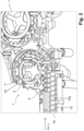
- FIG. 3 This is illustrated using an example star pocket 13.
- the solid black line in the star pocket 13 forms the actual outer contour as a given ACTUAL format part geometry FG, while the dashed line represents the DESIRED format part geometry VGF of the format part geometry section 10.1 specified by the actual container geometry.
- a format part 10 it is also possible for a format part 10 to have a plurality of format part geometry sections 10.1 which differ in their given format part geometry FG from the format part geometry VFG specified by the actual container geometry.
- the container treatment system 1 has at least one processing device 20 for adapting the given format part geometry FG of the at least one format part 10 of the container treatment system 1 to a format part geometry VFG predetermined by the actual container geometry.
- the given actual format part geometry FG can be adapted by means of the at least one processing device 20 to a target format part geometry VFG predetermined by the actual container geometry.
- the adaptation of the given format part geometry FG of the at least one format part 10 to a format part geometry VFG predetermined by the actual container geometry takes place by means of the processing device 20 in the installed, ie mounted, state of the format part 10 in the container treatment system 1, in which in particular a disassembly of the format part 10 from the container treatment system 1 is therefore not necessary.
- the processing device 20 can be connected to a Figures 6a and 6b schematically illustrated interface 50, for example an interface or a flange, can be arranged on the container treatment plant 1 or coupled to it in a fixed position.
- the interface 50 can also be arranged as in Figure 6b shown, be designed for supporting and position-fixed mounting of the processing device 20.
- the processing device 20 can be arranged in particular firmly, but detachably, on the container treatment system 1.
- interfaces 50 can also be provided along the container treatment line BS, so that the processing device 20 can be used as required at different interfaces 50 along the container treatment line BS.
- the processing device 20 may have an independent chassis 51, for example a roller chassis, for moving the processing device 20 on a floor level (cf. Figure 6b ). This enables simple and needs-based use of the processing device 20 at different interfaces 50 along the container treatment line BS.
- an independent chassis 51 for example a roller chassis
- the processing device 20 has at least one processing tool 21 for mechanical and/or welding processing of at least one format part geometry section 10.1 to a format part geometry VFG predetermined by the actual container geometry, which is arranged and guided on a guide and movement device 22.
- mechanical and/or welding processing is understood to mean both material removal and material build-up, i.e. material supply, to the at least one format part geometry section 10.1.
- the guide and movement device 22 can be designed as a robot kinematics having a plurality of rotation and/or movement axes, which has a plurality of robot arms 22.1, which are each connected to one another in a rotatable or pivotable manner about a rotation axis 22.2.
- the at least one processing tool 21 can be designed, for example, for machining, grinding, welding, or water jet-based machining of the at least one format part geometry section 10.1 of the corresponding format part 10.
- the at least one processing tool 21 can be arranged on the guide and movement device 22 via a changing device 23 (only indicated schematically), which is designed, for example, as a quick-coupling system.
- the changing device 23 enables easy exchange between different processing tools 21 on the guide and movement device 22.
- processing tools 21 for example a mechanical processing tool and a welding tool, are arranged on the guide and movement device 22.
- an additional suction device 24 can be provided on the guide and movement device 22 next to the at least one processing tool 21 in order to suck off processing material that arises during processing.
- the at least one processing tool 21 arranged on the guide and movement device 22 can be moved and actuated in a controlled manner by means of the guide and movement device 22, specifically depending on a control and evaluation routine SAR executed in a control unit 30.
- the processing tool 21 can be moved to the at least one format part geometry section 10.1 of the format part 10 to be processed and this at least one format part geometry section 10.1 can be adapted, i.e. processed, to a format part geometry VFG predetermined by the actual container geometry.
- At least one reworking section 28 is defined on the three-dimensional outer contour of the at least one format part geometry section 10.1 deviating from the specified format part geometry VFG, and based on this, the control and Evaluation routine SAR is generated, wherein the at least one processing tool 21 is then guided by means of the guide and movement device 22 at least to the determined reworking section 28 and the respective format part geometry section 10.1 assigned to the reworking section 28 is specifically adapted by means of the at least one processing tool 21 to the format part geometry VFG predetermined by the actual container geometry.
- the actual container geometry can be recorded, for example, by means of a recording device 25 and stored as a target processing data set SBD for the format part geometry VGF specified by the actual container geometry in the control unit 10 for the control and evaluation routine SAR.
- a reworking section 28 is assigned, for example, to the format part geometry section 10.1, which deviates from the specified format part geometry VFG in its given format part geometry FG.
- a detection device 25 can also be arranged on the guide and movement device 22 so that it can be exchanged by means of the changing device 23.
- the detection device 25 can also be designed to detect the actual container geometry and thus to provide the target processing set SBD.
- the detection device 25 can also be connected in a fixed manner to the processing device 20 via a carrier 25.1.
- the detection device 25 By means of the detection device 25, the at least one format part geometry section 10.1 that deviates from the actual container geometry in the given format part geometry FG can be optically detected and a reworking section 28 can subsequently be assigned to this.
- the detection device 25 is preferably guided along in a controlled manner by means of the guide and movement device 22.
- the detection device 25 and/or the guide and movement device 22 is provided with the Control unit 30 in which a control and evaluation routine SAR is executed.
- the control and evaluation routine SAR is also set up to control the guide and movement device 22 and the at least one processing tool 21.
- both the detection device 25 and the at least one processing tool 21 can be arranged on the guide and movement device 22, in such a way that before and/or after the optical detection of the given format part geometry FG and determination of the respective reworking section 28, this reworking section 28 is processed by means of the at least one processing tool 21 and it is possible to switch between the functionalities of the detection device 25 and/or the at least one processing tool 21.
- the detection device 25 is designed in particular to capture at least one image of the format part geometry section 10.1 that deviates from the actual container geometry in the given format part geometry FG and to assign a post-processing section 28 by means of an image processing unit, and in particular to measure the format part geometry section 10.1 as a given ACTUAL format part geometry FG and/or the actual container geometry as a predetermined DESIRED format part geometry VFG.
- the detection device 25 can advantageously be designed as a 3D camera system with a resolution of up to 5 ⁇ m or as a 3D laser measuring device, which is set up to generate a three-dimensional image of the at least one reworking section 28 and/or the actual container geometry.
- format part geometry sections 10.1 of the format part 10 that deviate from the predetermined format part geometry VFG can be detected and measured by means of the detection device 25.
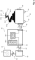
- FIG. 4 shows a schematic block diagram of the control unit 30 in which the control and evaluation routine SAR is executed.
- the control unit 30 has at least one processor unit 30.1 for executing the control and evaluation routine SAR, a memory unit 30.2 interacting with the processor unit 30.1 for at least temporarily storing process parameters and/or control data, and a first and second interface 40, 41.
- the processor unit 30.1 is in particular set up to convert the actual container geometry received at the first interface 40 of the control unit 30 into control and processing data SD by means of the control and evaluation routine SAR, or to define control commands that can be transmitted to the guide and movement device 22 via the second interface 41 in order to move them to a predetermined format part geometry section 10.1 of the three-dimensional outer contour of the format part 10 in a controlled manner depending on the control and processing data SD or control commands generated by means of the control and evaluation routine SAR and then to adapt them to the format part geometry VFG predetermined by the actual container geometry, i.e. to process them.
- Predefined control and processing modules SM for the control and evaluation routine SAR can also be stored in the storage unit 30.2.
- the target processing data set SBD of a format part 10 that has already been adapted to the format part geometry VFG specified by the actual container geometry using the processing tool 21 can also be stored, in particular saved, in the storage unit 30.2 as a processing module SM. This makes it particularly easy to re-produce a format part 10 that has already been produced in advance. Replacement format parts can also be easily reproduced on site in this way.
- Predefined processing steps can be assigned to predefined format part geometry sections 10.1 of the three-dimensional outer contour of the format part 10 using the control and processing modules SM, which can then be loaded using the control and evaluation routine SAR and executed in the processor unit 30.1.
- Such control and processing modules SM can also be used to individually specify the processing steps to be carried out for the different format part geometry sections 10.1.
- a wireless or wired data transmission path 42 can be provided for transmitting the control and processing data SD or control commands between the second interface 41 and the guide and movement device 22.
- the first interface 40 is also connected via a data transmission path 42 for transmitting the target processing set SBD to a computer unit 43, which can be designed as a personal computer, laptop or tablet, for example.
- Computer unit 43 is set up to generate the target processing set SBD and has the program routines required for this purpose.
- the computer unit 43 is connected to a display unit 44, which can be connected to the computer unit 43 or integrated therein.
- the display unit 44 is designed to display three-dimensional graphic objects, in particular the three-dimensional outer contour of the format parts 10 with their format part geometry section 10.1 and/or the actual container geometry based on the recorded 3D scan of the container 2.
- the target processing set SBD can be generated by means of the computer unit 33 in such a way that the format part geometry section 10.1 of the format parts 10 is assigned to the post-processing section 28 on a software basis.
- the processing device 20 can also be designed to process the format parts 10 next to or outside the container treatment line BS, i.e. in the removed, i.e. dismantled, state of the corresponding format part 10 from the container treatment system 1.
- the guide and movement device 22 can have a handling device 26, for example a gripper device, which can preferably be arranged on the guide and movement device 22 by means of the changing device 23.
- the corresponding format parts 10 can be dismantled on the container treatment system 1, for example removed, and moved to a workpiece carrier 27 assigned to the processing device 20.
- the workpiece carrier 27 serves to hold the format parts 10 in an indexed manner during processing of the same by means of the at least one processing tool 21.
- the processing device 20 can also be provided to adapt format parts 10' designed as raw format parts with a given format part geometry FG to a format part geometry VFG specified by the actual container geometry.
- the processing device 20 can, for example, store such raw format parts in the area of the workpiece carrier 27 and use them for processing when required. It can be carried out as a partial production from raw format parts which at least partially correspond in their given format part geometry FG to the actual container geometry as a specified Format part geometry VFG.
- the processing device 20 forms a type of processing center next to the container treatment line BS.
- the processing device 20 is separated from the container treatment section BS by means of at least one partition wall TW. This can prevent any protection that occurs during processing from entering the container treatment section BS.
Landscapes
- Filling Of Jars Or Cans And Processes For Cleaning And Sealing Jars (AREA)
- Specific Conveyance Elements (AREA)
- General Factory Administration (AREA)
Claims (17)
- Installation de traitement de récipient pour le traitement de récipients (2) ou similaires, comprenant au moins un trajet de traitement de récipient (BS) ainsi qu'au moins un élément de format (10) avec une géométrie d'élément de format (FG) qui est agencé le long de la voie de traitement de récipient (BSS) de manière amovible au niveau de l'installation de traitement de récipient (1) et est adapté au moins partiellement à une géométrie de récipient du récipient (2) à traiter ou similaires,
dans laquelle l'installation de traitement de récipient (1) présente au moins un dispositif d'usinage (20) pour l'adaptation de la géométrie d'élément de format (FG) donnée d'au moins un élément de format (10) de l'installation de traitement de récipient (1) à une géométrie d'élément de format (VFG) prédéfinie par la géométrie de récipient réelle, caractérisée en ce que l'au moins un dispositif d'usinage (20) adapte l'au moins un élément de format (10) en fonction d'une routine de commande et d'usinage (SAR) réalisée dans une unité de commande (30) à la géométrie d'élément de format (VFG) prédéfinie par la géométrie de récipient réelle. - Installation de traitement de récipient selon la revendication 1, caractérisée en ce que l'au moins un dispositif d'usinage (20) est agencé au moyen d'au moins une interface (50) fixement, toutefois de manière amovible, au niveau du trajet de traitement de récipient (BS) de l'installation de traitement de récipient (1).
- Installation de traitement de récipient selon la revendication 1 ou 2, caractérisée en ce que le dispositif d'usinage (20) est réalisé de manière déplaçable au moyen d'un mécanisme de roulement (51).
- Installation de traitement de récipient selon l'une quelconque des revendications précédentes, caractérisée en ce que le dispositif d'usinage (20) est réalisé pour l'adaptation de la géométrie d'élément de format (FG) donnée à une géométrie d'élément de format (VFG) prédéfinie par la géométrie de récipient réelle dans l'état monté et/ou démonté de l'élément de format (10) à usiner de manière correspondante de l'installation de traitement de récipient (1).
- Installation de traitement de récipient selon l'une quelconque des revendications précédentes, caractérisée en ce que le dispositif d'usinage (20) présente, pour l'adaptation de la géométrie d'élément de format (FG) donnée à une géométrie d'élément de format (VFG) de l'élément de format (10) prédéfinie par la géométrie de récipient réelle, au moins un outil d'usinage (21) agencé au niveau d'un dispositif de guidage et de déplacement (22) pour l'usinage mécanique et/ou par soudage au moins d'une section de géométrie d'élément de format (10.1 de l'élément de format (10) correspondant.
- Installation de traitement de récipient selon la revendication 5, caractérisée en ce que le dispositif de guidage et de déplacement (22) est réalisé en tant que cinématique de robot présentant plusieurs axes de rotation et/ou de déplacement qui présente un ou plusieurs bras de robot (22.1) qui sont reliés entre eux respectivement de manière rotative ou pivotante autour d'un axe de rotation (22.2).
- Installation de traitement de récipient selon la revendication 5 ou 6, caractérisée en ce que l'au moins un outil d'usinage (21) est réalisé pour l'usinage par enlèvement de copeaux et/ou affûtage et/ou soudage à superposition et/ou basé sur un jet d'eau d'au moins une section de géométrie d'élément de format (10.1).
- Installation de traitement de récipient selon l'une quelconque des revendications 5 à 7, caractérisée en ce que l'au moins un outil d'usinage (21) est agencé au moyen d'un dispositif de changement (23) au niveau du dispositif de guidage et de déplacement (22).
- Installation de traitement de récipient selon l'une quelconque des revendications 5 à 8, caractérisée en ce qu'en outre, un dispositif d'aspiration (24) est prévu au niveau du dispositif de guidage et de déplacement (22) à côté de l'au moins un outil d'usinage (21).
- Installation de traitement de récipient selon l'une quelconque des revendications précédentes, caractérisée en ce que l'installation de traitement de récipient (1) présente au moins un dispositif de détection (25) qui est réalisé afin de détecter optiquement la géométrie d'élément de format FG donnée, la géométrie de récipient réelle ainsi que la section de géométrie d'élément de format (10.1) différente, à adapter à celle-ci et de transmettre ces données à une unité de commande et d'évaluation, pour la détermination du type et de l'étendue d'un post-usinage nécessaire d'une ou plusieurs sections de post-usinage (28).
- Installation de traitement de récipient selon la revendication 10, caractérisée en ce que l'au moins un dispositif de détection (25) est agencé au niveau d'un support (25.1) et/ou du dispositif de guidage et de déplacement (22).
- Installation de traitement de récipient selon la revendication 10 ou 11, caractérisée en ce que l'au moins un dispositif de détection (25) est réalisé en tant que système de caméra 3D ou en tant que dispositif de mesure laser 3D.
- Installation de traitement de récipient selon l'une quelconque des revendications précédentes, caractérisée en ce que l'unité de commande (30) est réalisée afin de définir en fonction de la géométrie d'élément de format (VFG) prédéfinie par la géométrie de récipient réelle pour l'élément de format (10) à usiner au niveau de l'au moins une section de géométrie d'élément de format (10.1) différente de la géométrie d'élément de format (VFG) prédéfinie au moins une section de post-usinage (28) sur son contour extérieur en trois dimensions, et à partir de celle-ci de générer la route de commande et d'évaluation (SAR), dans laquelle de guider de manière commandée ensuite l'au moins un outil d'usinage (21) au moyen du dispositif de guidage et de déplacement (22) au moins au niveau de la section de post-usinage (28) calculée et d'adapter la section de géométrie d'élément de format (10.1) respective associée à la section de post-usinage (28) de manière ciblée au moyen de l'au moins un outil d'usinage (21) à la géométrie d'élément de format (VFG) prédéfinie par la géométrie de récipient réelle.
- Installation de traitement de récipient selon l'une quelconque des revendications précédentes, caractérisée en ce que le dispositif de guidage et de déplacement (22) présente un dispositif de manipulation (26) qui peut être agencé de préférence au moyen du dispositif de changement (23) au niveau du dispositif de guidage et de déplacement (22).
- Installation de traitement de récipient selon l'une quelconque des revendications précédentes, caractérisée en ce que le dispositif d'usinage (20) présente un porte-pièce (27) pour le support indexé des éléments de format (10).
- Installation de traitement de récipient selon l'une quelconque des revendications précédentes, caractérisée en ce que le dispositif d'usinage (20) est séparé au moyen d'au moins une paroi de séparation (TW) du trajet de traitement de récipient (BS).
- Procédé d'adaptation d'éléments de format d'une installation de traitement de récipient pour le traitement de récipients (2) ou similaires, comprenant au moins un trajet de traitement de récipient (BS), dans lequel le long du trajet de traitement de récipient (BS), au moins un élément de format (10) adapté au moins partiellement à une géométrie de récipient du récipient (2) à traiter ou similaire est prévu avec une géométrie d'élément de format (FG) donnée, lequel est agencé de manière amovible au niveau de l'installation de traitement de récipient (1), caractérisé en ce que la géométrie d'élément de format (FG) donnée d'au moins un élément de format (10) est adaptée au moyen d'au moins un dispositif d'usinage (20) réalisé selon les revendications 1 à 16 à une géométrie d'élément de format (VFG) prédéfinie par la géométrie de récipient réelle.
Applications Claiming Priority (2)
| Application Number | Priority Date | Filing Date | Title |
|---|---|---|---|
| DE102019109446.1A DE102019109446A1 (de) | 2019-04-10 | 2019-04-10 | Behälterbehandlungsanlage zum Behandeln von Behältern oder dergleichen |
| PCT/EP2020/055507 WO2020207665A1 (fr) | 2019-04-10 | 2020-03-03 | Installation de traitement de récipients pour le traitement de récipients ou similaires |
Publications (2)
| Publication Number | Publication Date |
|---|---|
| EP3953280A1 EP3953280A1 (fr) | 2022-02-16 |
| EP3953280B1 true EP3953280B1 (fr) | 2024-05-01 |
Family
ID=69846036
Family Applications (1)
| Application Number | Title | Priority Date | Filing Date |
|---|---|---|---|
| EP20712214.4A Active EP3953280B1 (fr) | 2019-04-10 | 2020-03-03 | Installation de traitement de récipients pour le traitement de récipients ou similaires |
Country Status (5)
| Country | Link |
|---|---|
| US (1) | US12024415B2 (fr) |
| EP (1) | EP3953280B1 (fr) |
| CN (1) | CN113646246B (fr) |
| DE (1) | DE102019109446A1 (fr) |
| WO (1) | WO2020207665A1 (fr) |
Families Citing this family (1)
| Publication number | Priority date | Publication date | Assignee | Title |
|---|---|---|---|---|
| DE102019109446A1 (de) * | 2019-04-10 | 2020-10-15 | Khs Gmbh | Behälterbehandlungsanlage zum Behandeln von Behältern oder dergleichen |
Family Cites Families (19)
| Publication number | Priority date | Publication date | Assignee | Title |
|---|---|---|---|---|
| US1574307A (en) * | 1924-04-07 | 1926-02-23 | U S Bottlers Machinery Co | Bottle adapter for bottle-filling machines |
| JPS50724A (fr) * | 1973-05-02 | 1975-01-07 | ||
| US4124112A (en) * | 1977-05-23 | 1978-11-07 | Owens-Illinois, Inc. | Odd-shaped container indexing starwheel |
| JPH01220634A (ja) * | 1988-02-24 | 1989-09-04 | Shibuya Kogyo Co Ltd | 物品受渡し装置 |
| JP2907242B2 (ja) * | 1991-06-21 | 1999-06-21 | 澁谷工業株式会社 | 容器処理装置 |
| DE4242925A1 (de) * | 1992-12-18 | 1994-06-23 | Khs Masch & Anlagenbau Ag | Transporteinrichtung für Maschinen zum Behandeln von Flaschen o. dgl. Behälter |
| WO2005030616A2 (fr) * | 2003-09-25 | 2005-04-07 | Diageo Plc | Transporteur a roues en etoile reglables |
| ITPR20050051A1 (it) * | 2005-09-12 | 2007-03-13 | Lanfranchi Srl | Trasportatore a stella ruotante per bottiglie o contenitori vuoti in plastica. |
| GB2452996B (en) * | 2007-09-24 | 2010-12-22 | Zepf Technologies Uk Ltd | Adjustable star wheel |
| DE102008010076A1 (de) * | 2008-02-19 | 2009-08-20 | Khs Ag | Anlage zum Ver- und/oder Bearbeiten von Packmitteln sowie Verfahren zur formatgerechten Einstellung einer solchen Anlage |
| ITPD20080176A1 (it) * | 2008-06-17 | 2009-12-18 | Gruppo Bertolaso Spa | Apparecchiatura a stella per il trasferimento di contenitori |
| EP2383081B1 (fr) * | 2010-04-29 | 2014-06-04 | Trumpf Sachsen GmbH | Procédé de fabrication pour produire un produit à manipuler |
| DE102011054890A1 (de) * | 2011-10-28 | 2013-05-02 | Krones Aktiengesellschaft | Behälterbehandlungsanlage und Handhabungsvorrichtung |
| BG111307A (bg) * | 2012-09-19 | 2014-03-31 | "Индекс - 6" Оод | Устройство със сменяеми държачи за захващане и пренасяне на съдове |
| DE102012108953A1 (de) * | 2012-09-21 | 2014-03-27 | Khs Gmbh | Werkzeugloser Austausch von Formatteilen |
| DE102013113292A1 (de) * | 2013-12-02 | 2015-06-18 | Khs Gmbh | Transportstern mit verstellbaren Sterntaschen |
| DE202014100458U1 (de) * | 2014-02-03 | 2014-03-18 | Stefan Fietkau | Vorrichtung zum Ansaugen und/oder Transportieren und/oder Montieren von Bauteilen |
| DE102017209838A1 (de) * | 2017-06-12 | 2018-12-13 | Krones Ag | Behälterbehandlungsanlage zum Behandeln von Behältern |
| DE102019109446A1 (de) * | 2019-04-10 | 2020-10-15 | Khs Gmbh | Behälterbehandlungsanlage zum Behandeln von Behältern oder dergleichen |
-
2019
- 2019-04-10 DE DE102019109446.1A patent/DE102019109446A1/de not_active Withdrawn
-
2020
- 2020-03-03 WO PCT/EP2020/055507 patent/WO2020207665A1/fr not_active Ceased
- 2020-03-03 EP EP20712214.4A patent/EP3953280B1/fr active Active
- 2020-03-03 CN CN202080027115.3A patent/CN113646246B/zh active Active
-
2021
- 2021-10-07 US US17/495,943 patent/US12024415B2/en active Active
Also Published As
| Publication number | Publication date |
|---|---|
| US20220024745A1 (en) | 2022-01-27 |
| EP3953280A1 (fr) | 2022-02-16 |
| CN113646246B (zh) | 2023-08-15 |
| US12024415B2 (en) | 2024-07-02 |
| DE102019109446A1 (de) | 2020-10-15 |
| WO2020207665A1 (fr) | 2020-10-15 |
| CN113646246A (zh) | 2021-11-12 |
Similar Documents
| Publication | Publication Date | Title |
|---|---|---|
| EP2492041B1 (fr) | Dispositif avec un dispositif d'usinage de tuyau ; Méthode de déchargement d'un tuyau utilisant un tel dispositif | |
| EP3106241B1 (fr) | Machine-outil et procédé destinés a l'évacuation de parties d'une pièce à usiner | |
| EP2777873B1 (fr) | Centre de traitement vertical en forme de portique doté d'un stockage de magasin d'outils intégré côté machine et procédé de changement d'outil | |
| EP1952939A1 (fr) | Dispositif de manipulation d'une pièce à usiner | |
| DE102005043602A1 (de) | Zahnradbearbeitungsmaschine sowie Verfahren zum Betrieb einer solchen Zahnradbearbeitungsmaschine | |
| EP3641972B1 (fr) | Systeme de déplacement et machine à tailler les engrenages | |
| DE102020208798A1 (de) | Werkstückfördersystem für eine transferpressenmaschine | |
| DE202017106030U1 (de) | Honmaschine und Verwendung einer Honmaschine | |
| EP2363288A1 (fr) | Dispositif et procédé d'alignement d'objets | |
| DE10236342B4 (de) | Verfahren zum Bestücken von Werkzeugen in Werkzeugmagazinen sowie Vorrichtung zur Durchführung eines solchen Verfahrens | |
| DE3542496A1 (de) | Verfahren und vorrichtung zum zufuehren von montageteilen | |
| EP2484485A1 (fr) | Procédé et système de chargement et de déchargement d'une machine-outil avec des outils | |
| DE102014113319B4 (de) | Drahtformvorrichtung | |
| EP3031572A1 (fr) | Dispositif de changement d'outil destine a etre utilise dans un centre d'usinage et centre d'usinage destine a l'usinage mecanique d'une piece a usiner | |
| EP1884498A1 (fr) | Agencement destiné à la fabrication de corps en verre | |
| EP3338941B1 (fr) | Machine à transfert rotatif | |
| DE19713106B4 (de) | Verfahren und Vorrichtung zum Zuführen von Werkstücken | |
| EP1725501B1 (fr) | Machine de faconnage du verre | |
| DE102018133552B4 (de) | Biegemaschine, Bearbeitungslinie und Verfahren zum Biegen | |
| EP3953280A1 (fr) | Installation de traitement de récipients pour le traitement de récipients ou similaires | |
| DE19721330C2 (de) | Vorrichtung zum Zuführen, Aufnehmen und Entladen von Werkstücken, wie Rohren oder Stangen | |
| EP0589160A1 (fr) | Procédé et dispositif pour l'ébavurage et le traitement ultérieur de pièces, en particulier de pieces en céramique | |
| DE102014100476A1 (de) | Roboter-Stanzzelle | |
| EP2210701A1 (fr) | Système de fabrication linéaire | |
| EP3124153B1 (fr) | Dispositif d'usinage de pièces à usiner, notamment des lames de scie |
Legal Events
| Date | Code | Title | Description |
|---|---|---|---|
| STAA | Information on the status of an ep patent application or granted ep patent |
Free format text: STATUS: UNKNOWN |
|
| STAA | Information on the status of an ep patent application or granted ep patent |
Free format text: STATUS: THE INTERNATIONAL PUBLICATION HAS BEEN MADE |
|
| PUAI | Public reference made under article 153(3) epc to a published international application that has entered the european phase |
Free format text: ORIGINAL CODE: 0009012 |
|
| STAA | Information on the status of an ep patent application or granted ep patent |
Free format text: STATUS: REQUEST FOR EXAMINATION WAS MADE |
|
| 17P | Request for examination filed |
Effective date: 20211110 |
|
| AK | Designated contracting states |
Kind code of ref document: A1 Designated state(s): AL AT BE BG CH CY CZ DE DK EE ES FI FR GB GR HR HU IE IS IT LI LT LU LV MC MK MT NL NO PL PT RO RS SE SI SK SM TR |
|
| DAV | Request for validation of the european patent (deleted) | ||
| DAX | Request for extension of the european patent (deleted) | ||
| GRAP | Despatch of communication of intention to grant a patent |
Free format text: ORIGINAL CODE: EPIDOSNIGR1 |
|
| STAA | Information on the status of an ep patent application or granted ep patent |
Free format text: STATUS: GRANT OF PATENT IS INTENDED |
|
| INTG | Intention to grant announced |
Effective date: 20231205 |
|
| GRAS | Grant fee paid |
Free format text: ORIGINAL CODE: EPIDOSNIGR3 |
|
| GRAA | (expected) grant |
Free format text: ORIGINAL CODE: 0009210 |
|
| STAA | Information on the status of an ep patent application or granted ep patent |
Free format text: STATUS: THE PATENT HAS BEEN GRANTED |
|
| AK | Designated contracting states |
Kind code of ref document: B1 Designated state(s): AL AT BE BG CH CY CZ DE DK EE ES FI FR GB GR HR HU IE IS IT LI LT LU LV MC MK MT NL NO PL PT RO RS SE SI SK SM TR |
|
| REG | Reference to a national code |
Ref country code: GB Ref legal event code: FG4D Free format text: NOT ENGLISH |
|
| REG | Reference to a national code |
Ref country code: CH Ref legal event code: EP |
|
| REG | Reference to a national code |
Ref country code: DE Ref legal event code: R096 Ref document number: 502020007849 Country of ref document: DE |
|
| REG | Reference to a national code |
Ref country code: IE Ref legal event code: FG4D Free format text: LANGUAGE OF EP DOCUMENT: GERMAN |
|
| REG | Reference to a national code |
Ref country code: LT Ref legal event code: MG9D |
|
| REG | Reference to a national code |
Ref country code: NL Ref legal event code: MP Effective date: 20240501 |
|
| PG25 | Lapsed in a contracting state [announced via postgrant information from national office to epo] |
Ref country code: IS Free format text: LAPSE BECAUSE OF FAILURE TO SUBMIT A TRANSLATION OF THE DESCRIPTION OR TO PAY THE FEE WITHIN THE PRESCRIBED TIME-LIMIT Effective date: 20240901 |
|
| PG25 | Lapsed in a contracting state [announced via postgrant information from national office to epo] |
Ref country code: BG Free format text: LAPSE BECAUSE OF FAILURE TO SUBMIT A TRANSLATION OF THE DESCRIPTION OR TO PAY THE FEE WITHIN THE PRESCRIBED TIME-LIMIT Effective date: 20240501 |
|
| PG25 | Lapsed in a contracting state [announced via postgrant information from national office to epo] |
Ref country code: FI Free format text: LAPSE BECAUSE OF FAILURE TO SUBMIT A TRANSLATION OF THE DESCRIPTION OR TO PAY THE FEE WITHIN THE PRESCRIBED TIME-LIMIT Effective date: 20240501 Ref country code: HR Free format text: LAPSE BECAUSE OF FAILURE TO SUBMIT A TRANSLATION OF THE DESCRIPTION OR TO PAY THE FEE WITHIN THE PRESCRIBED TIME-LIMIT Effective date: 20240501 |
|
| PG25 | Lapsed in a contracting state [announced via postgrant information from national office to epo] |
Ref country code: GR Free format text: LAPSE BECAUSE OF FAILURE TO SUBMIT A TRANSLATION OF THE DESCRIPTION OR TO PAY THE FEE WITHIN THE PRESCRIBED TIME-LIMIT Effective date: 20240802 |
|
| PG25 | Lapsed in a contracting state [announced via postgrant information from national office to epo] |
Ref country code: PT Free format text: LAPSE BECAUSE OF FAILURE TO SUBMIT A TRANSLATION OF THE DESCRIPTION OR TO PAY THE FEE WITHIN THE PRESCRIBED TIME-LIMIT Effective date: 20240902 |
|
| PG25 | Lapsed in a contracting state [announced via postgrant information from national office to epo] |
Ref country code: NL Free format text: LAPSE BECAUSE OF FAILURE TO SUBMIT A TRANSLATION OF THE DESCRIPTION OR TO PAY THE FEE WITHIN THE PRESCRIBED TIME-LIMIT Effective date: 20240501 |
|
| PG25 | Lapsed in a contracting state [announced via postgrant information from national office to epo] |
Ref country code: ES Free format text: LAPSE BECAUSE OF FAILURE TO SUBMIT A TRANSLATION OF THE DESCRIPTION OR TO PAY THE FEE WITHIN THE PRESCRIBED TIME-LIMIT Effective date: 20240501 |
|
| PG25 | Lapsed in a contracting state [announced via postgrant information from national office to epo] |
Ref country code: PL Free format text: LAPSE BECAUSE OF FAILURE TO SUBMIT A TRANSLATION OF THE DESCRIPTION OR TO PAY THE FEE WITHIN THE PRESCRIBED TIME-LIMIT Effective date: 20240501 |
|
| PG25 | Lapsed in a contracting state [announced via postgrant information from national office to epo] |
Ref country code: LV Free format text: LAPSE BECAUSE OF FAILURE TO SUBMIT A TRANSLATION OF THE DESCRIPTION OR TO PAY THE FEE WITHIN THE PRESCRIBED TIME-LIMIT Effective date: 20240501 |
|
| PG25 | Lapsed in a contracting state [announced via postgrant information from national office to epo] |
Ref country code: PT Free format text: LAPSE BECAUSE OF FAILURE TO SUBMIT A TRANSLATION OF THE DESCRIPTION OR TO PAY THE FEE WITHIN THE PRESCRIBED TIME-LIMIT Effective date: 20240902 Ref country code: PL Free format text: LAPSE BECAUSE OF FAILURE TO SUBMIT A TRANSLATION OF THE DESCRIPTION OR TO PAY THE FEE WITHIN THE PRESCRIBED TIME-LIMIT Effective date: 20240501 Ref country code: NO Free format text: LAPSE BECAUSE OF FAILURE TO SUBMIT A TRANSLATION OF THE DESCRIPTION OR TO PAY THE FEE WITHIN THE PRESCRIBED TIME-LIMIT Effective date: 20240801 Ref country code: NL Free format text: LAPSE BECAUSE OF FAILURE TO SUBMIT A TRANSLATION OF THE DESCRIPTION OR TO PAY THE FEE WITHIN THE PRESCRIBED TIME-LIMIT Effective date: 20240501 Ref country code: LV Free format text: LAPSE BECAUSE OF FAILURE TO SUBMIT A TRANSLATION OF THE DESCRIPTION OR TO PAY THE FEE WITHIN THE PRESCRIBED TIME-LIMIT Effective date: 20240501 Ref country code: IS Free format text: LAPSE BECAUSE OF FAILURE TO SUBMIT A TRANSLATION OF THE DESCRIPTION OR TO PAY THE FEE WITHIN THE PRESCRIBED TIME-LIMIT Effective date: 20240901 Ref country code: HR Free format text: LAPSE BECAUSE OF FAILURE TO SUBMIT A TRANSLATION OF THE DESCRIPTION OR TO PAY THE FEE WITHIN THE PRESCRIBED TIME-LIMIT Effective date: 20240501 Ref country code: GR Free format text: LAPSE BECAUSE OF FAILURE TO SUBMIT A TRANSLATION OF THE DESCRIPTION OR TO PAY THE FEE WITHIN THE PRESCRIBED TIME-LIMIT Effective date: 20240802 Ref country code: FI Free format text: LAPSE BECAUSE OF FAILURE TO SUBMIT A TRANSLATION OF THE DESCRIPTION OR TO PAY THE FEE WITHIN THE PRESCRIBED TIME-LIMIT Effective date: 20240501 Ref country code: ES Free format text: LAPSE BECAUSE OF FAILURE TO SUBMIT A TRANSLATION OF THE DESCRIPTION OR TO PAY THE FEE WITHIN THE PRESCRIBED TIME-LIMIT Effective date: 20240501 Ref country code: BG Free format text: LAPSE BECAUSE OF FAILURE TO SUBMIT A TRANSLATION OF THE DESCRIPTION OR TO PAY THE FEE WITHIN THE PRESCRIBED TIME-LIMIT Effective date: 20240501 Ref country code: RS Free format text: LAPSE BECAUSE OF FAILURE TO SUBMIT A TRANSLATION OF THE DESCRIPTION OR TO PAY THE FEE WITHIN THE PRESCRIBED TIME-LIMIT Effective date: 20240801 |
|
| PG25 | Lapsed in a contracting state [announced via postgrant information from national office to epo] |
Ref country code: DK Free format text: LAPSE BECAUSE OF FAILURE TO SUBMIT A TRANSLATION OF THE DESCRIPTION OR TO PAY THE FEE WITHIN THE PRESCRIBED TIME-LIMIT Effective date: 20240501 |
|
| PG25 | Lapsed in a contracting state [announced via postgrant information from national office to epo] |
Ref country code: EE Free format text: LAPSE BECAUSE OF FAILURE TO SUBMIT A TRANSLATION OF THE DESCRIPTION OR TO PAY THE FEE WITHIN THE PRESCRIBED TIME-LIMIT Effective date: 20240501 |
|
| PG25 | Lapsed in a contracting state [announced via postgrant information from national office to epo] |
Ref country code: CZ Free format text: LAPSE BECAUSE OF FAILURE TO SUBMIT A TRANSLATION OF THE DESCRIPTION OR TO PAY THE FEE WITHIN THE PRESCRIBED TIME-LIMIT Effective date: 20240501 |
|
| PG25 | Lapsed in a contracting state [announced via postgrant information from national office to epo] |
Ref country code: SK Free format text: LAPSE BECAUSE OF FAILURE TO SUBMIT A TRANSLATION OF THE DESCRIPTION OR TO PAY THE FEE WITHIN THE PRESCRIBED TIME-LIMIT Effective date: 20240501 Ref country code: RO Free format text: LAPSE BECAUSE OF FAILURE TO SUBMIT A TRANSLATION OF THE DESCRIPTION OR TO PAY THE FEE WITHIN THE PRESCRIBED TIME-LIMIT Effective date: 20240501 |
|
| PG25 | Lapsed in a contracting state [announced via postgrant information from national office to epo] |
Ref country code: SM Free format text: LAPSE BECAUSE OF FAILURE TO SUBMIT A TRANSLATION OF THE DESCRIPTION OR TO PAY THE FEE WITHIN THE PRESCRIBED TIME-LIMIT Effective date: 20240501 |
|
| PG25 | Lapsed in a contracting state [announced via postgrant information from national office to epo] |
Ref country code: SM Free format text: LAPSE BECAUSE OF FAILURE TO SUBMIT A TRANSLATION OF THE DESCRIPTION OR TO PAY THE FEE WITHIN THE PRESCRIBED TIME-LIMIT Effective date: 20240501 Ref country code: SK Free format text: LAPSE BECAUSE OF FAILURE TO SUBMIT A TRANSLATION OF THE DESCRIPTION OR TO PAY THE FEE WITHIN THE PRESCRIBED TIME-LIMIT Effective date: 20240501 Ref country code: RO Free format text: LAPSE BECAUSE OF FAILURE TO SUBMIT A TRANSLATION OF THE DESCRIPTION OR TO PAY THE FEE WITHIN THE PRESCRIBED TIME-LIMIT Effective date: 20240501 Ref country code: EE Free format text: LAPSE BECAUSE OF FAILURE TO SUBMIT A TRANSLATION OF THE DESCRIPTION OR TO PAY THE FEE WITHIN THE PRESCRIBED TIME-LIMIT Effective date: 20240501 Ref country code: DK Free format text: LAPSE BECAUSE OF FAILURE TO SUBMIT A TRANSLATION OF THE DESCRIPTION OR TO PAY THE FEE WITHIN THE PRESCRIBED TIME-LIMIT Effective date: 20240501 Ref country code: CZ Free format text: LAPSE BECAUSE OF FAILURE TO SUBMIT A TRANSLATION OF THE DESCRIPTION OR TO PAY THE FEE WITHIN THE PRESCRIBED TIME-LIMIT Effective date: 20240501 |
|
| REG | Reference to a national code |
Ref country code: DE Ref legal event code: R097 Ref document number: 502020007849 Country of ref document: DE |
|
| PG25 | Lapsed in a contracting state [announced via postgrant information from national office to epo] |
Ref country code: IT Free format text: LAPSE BECAUSE OF FAILURE TO SUBMIT A TRANSLATION OF THE DESCRIPTION OR TO PAY THE FEE WITHIN THE PRESCRIBED TIME-LIMIT Effective date: 20240501 |
|
| PLBE | No opposition filed within time limit |
Free format text: ORIGINAL CODE: 0009261 |
|
| STAA | Information on the status of an ep patent application or granted ep patent |
Free format text: STATUS: NO OPPOSITION FILED WITHIN TIME LIMIT |
|
| 26N | No opposition filed |
Effective date: 20250204 |
|
| PG25 | Lapsed in a contracting state [announced via postgrant information from national office to epo] |
Ref country code: SI Free format text: LAPSE BECAUSE OF FAILURE TO SUBMIT A TRANSLATION OF THE DESCRIPTION OR TO PAY THE FEE WITHIN THE PRESCRIBED TIME-LIMIT Effective date: 20240501 |
|
| PG25 | Lapsed in a contracting state [announced via postgrant information from national office to epo] |
Ref country code: SE Free format text: LAPSE BECAUSE OF FAILURE TO SUBMIT A TRANSLATION OF THE DESCRIPTION OR TO PAY THE FEE WITHIN THE PRESCRIBED TIME-LIMIT Effective date: 20240501 |
|
| PG25 | Lapsed in a contracting state [announced via postgrant information from national office to epo] |
Ref country code: MC Free format text: LAPSE BECAUSE OF FAILURE TO SUBMIT A TRANSLATION OF THE DESCRIPTION OR TO PAY THE FEE WITHIN THE PRESCRIBED TIME-LIMIT Effective date: 20240501 |
|
| REG | Reference to a national code |
Ref country code: CH Ref legal event code: H13 Free format text: ST27 STATUS EVENT CODE: U-0-0-H10-H13 (AS PROVIDED BY THE NATIONAL OFFICE) Effective date: 20251023 |
|
| PG25 | Lapsed in a contracting state [announced via postgrant information from national office to epo] |
Ref country code: LU Free format text: LAPSE BECAUSE OF NON-PAYMENT OF DUE FEES Effective date: 20250303 |
|
| GBPC | Gb: european patent ceased through non-payment of renewal fee |
Effective date: 20250303 |
|
| REG | Reference to a national code |
Ref country code: BE Ref legal event code: MM Effective date: 20250331 |
|
| PG25 | Lapsed in a contracting state [announced via postgrant information from national office to epo] |
Ref country code: GB Free format text: LAPSE BECAUSE OF NON-PAYMENT OF DUE FEES Effective date: 20250303 |
|
| P01 | Opt-out of the competence of the unified patent court (upc) registered |
Free format text: CASE NUMBER: UPC_APP_0014568_3953280/2025 Effective date: 20251125 |
|
| PG25 | Lapsed in a contracting state [announced via postgrant information from national office to epo] |
Ref country code: FR Free format text: LAPSE BECAUSE OF NON-PAYMENT OF DUE FEES Effective date: 20250331 |
|
| PG25 | Lapsed in a contracting state [announced via postgrant information from national office to epo] |
Ref country code: BE Free format text: LAPSE BECAUSE OF NON-PAYMENT OF DUE FEES Effective date: 20250331 |
|
| PG25 | Lapsed in a contracting state [announced via postgrant information from national office to epo] |
Ref country code: CH Free format text: LAPSE BECAUSE OF NON-PAYMENT OF DUE FEES Effective date: 20250331 |
|
| PG25 | Lapsed in a contracting state [announced via postgrant information from national office to epo] |
Ref country code: IE Free format text: LAPSE BECAUSE OF NON-PAYMENT OF DUE FEES Effective date: 20250303 |
|
| PGFP | Annual fee paid to national office [announced via postgrant information from national office to epo] |
Ref country code: DE Payment date: 20260319 Year of fee payment: 7 |