EP3957451A1 - Procédé de perçage amélioré à l'aide d'un appareil de perçage dans un trou de perçage existant et système de perçage - Google Patents
Procédé de perçage amélioré à l'aide d'un appareil de perçage dans un trou de perçage existant et système de perçage Download PDFInfo
- Publication number
- EP3957451A1 EP3957451A1 EP20191325.8A EP20191325A EP3957451A1 EP 3957451 A1 EP3957451 A1 EP 3957451A1 EP 20191325 A EP20191325 A EP 20191325A EP 3957451 A1 EP3957451 A1 EP 3957451A1
- Authority
- EP
- European Patent Office
- Prior art keywords
- drilling
- drilling device
- operating state
- borehole
- drill
- Prior art date
- Legal status (The legal status is an assumption and is not a legal conclusion. Google has not performed a legal analysis and makes no representation as to the accuracy of the status listed.)
- Withdrawn
Links
- 238000005553 drilling Methods 0.000 title claims abstract description 194
- 238000000034 method Methods 0.000 title claims abstract description 62
- 238000010079 rubber tapping Methods 0.000 claims abstract description 25
- 230000001276 controlling effect Effects 0.000 description 2
- 239000000758 substrate Substances 0.000 description 2
- 230000007704 transition Effects 0.000 description 2
- FGUUSXIOTUKUDN-IBGZPJMESA-N C1(=CC=CC=C1)N1C2=C(NC([C@H](C1)NC=1OC(=NN=1)C1=CC=CC=C1)=O)C=CC=C2 Chemical compound C1(=CC=CC=C1)N1C2=C(NC([C@H](C1)NC=1OC(=NN=1)C1=CC=CC=C1)=O)C=CC=C2 FGUUSXIOTUKUDN-IBGZPJMESA-N 0.000 description 1
- 208000036829 Device dislocation Diseases 0.000 description 1
- 238000004364 calculation method Methods 0.000 description 1
- 230000015556 catabolic process Effects 0.000 description 1
- 238000006243 chemical reaction Methods 0.000 description 1
- 238000006731 degradation reaction Methods 0.000 description 1
- 230000001419 dependent effect Effects 0.000 description 1
- 229910003460 diamond Inorganic materials 0.000 description 1
- 239000010432 diamond Substances 0.000 description 1
- 230000000694 effects Effects 0.000 description 1
- 238000005259 measurement Methods 0.000 description 1
- 230000001105 regulatory effect Effects 0.000 description 1
- 239000011435 rock Substances 0.000 description 1
- 230000001960 triggered effect Effects 0.000 description 1
Images


Classifications
-
- B—PERFORMING OPERATIONS; TRANSPORTING
- B28—WORKING CEMENT, CLAY, OR STONE
- B28D—WORKING STONE OR STONE-LIKE MATERIALS
- B28D1/00—Working stone or stone-like materials, e.g. brick, concrete or glass, not provided for elsewhere; Machines, devices, tools therefor
- B28D1/14—Working stone or stone-like materials, e.g. brick, concrete or glass, not provided for elsewhere; Machines, devices, tools therefor by boring or drilling
-
- B—PERFORMING OPERATIONS; TRANSPORTING
- B23—MACHINE TOOLS; METAL-WORKING NOT OTHERWISE PROVIDED FOR
- B23B—TURNING; BORING
- B23B35/00—Methods for boring or drilling, or for working essentially requiring the use of boring or drilling machines; Use of auxiliary equipment in connection with such methods
-
- B—PERFORMING OPERATIONS; TRANSPORTING
- B28—WORKING CEMENT, CLAY, OR STONE
- B28D—WORKING STONE OR STONE-LIKE MATERIALS
- B28D1/00—Working stone or stone-like materials, e.g. brick, concrete or glass, not provided for elsewhere; Machines, devices, tools therefor
- B28D1/02—Working stone or stone-like materials, e.g. brick, concrete or glass, not provided for elsewhere; Machines, devices, tools therefor by sawing
- B28D1/04—Working stone or stone-like materials, e.g. brick, concrete or glass, not provided for elsewhere; Machines, devices, tools therefor by sawing with circular or cylindrical saw-blades or saw-discs
- B28D1/041—Working stone or stone-like materials, e.g. brick, concrete or glass, not provided for elsewhere; Machines, devices, tools therefor by sawing with circular or cylindrical saw-blades or saw-discs with cylinder saws, e.g. trepanning; saw cylinders, e.g. having their cutting rim equipped with abrasive particles
-
- B—PERFORMING OPERATIONS; TRANSPORTING
- B28—WORKING CEMENT, CLAY, OR STONE
- B28D—WORKING STONE OR STONE-LIKE MATERIALS
- B28D7/00—Accessories specially adapted for use with machines or devices of the preceding groups
- B28D7/005—Devices for the automatic drive or the program control of the machines
-
- B—PERFORMING OPERATIONS; TRANSPORTING
- B23—MACHINE TOOLS; METAL-WORKING NOT OTHERWISE PROVIDED FOR
- B23B—TURNING; BORING
- B23B2226/00—Materials of tools or workpieces not comprising a metal
- B23B2226/75—Stone, rock or concrete
Definitions
- the present invention relates to a method for improved tapping with a drill in an existing well.
- the drilling device can be operated in a first and in a second operating state, it being possible to switch between the operating states depending on a comparison between friction data and depending on a direction of movement of the drilling device.
- the invention relates to a drilling system that includes a drilling device and an autofeed device for generating a feed for the drilling device.
- the drilling system is preferably set up to implement the proposed tapping method. It is also designed such that switching between the first operating state and the second operating state takes place by comparing an actual value of a friction torque and a reference value in conjunction with determining a direction of movement of the drilling device.
- Machine tools are known in the prior art that are equipped with an autofeed device or work together with one.
- a system made up of a machine tool and an autofeed device is preferably referred to as a drilling system within the meaning of the invention.
- An autofeed device is preferably set up to bring about a forward movement of the machine tool or to control such a forward movement. For this purpose, a feed generated by the autofeed device can be transmitted to the machine tool, so that the machine tool is driven further into the subsurface to be machined.
- control devices When controlling the forward movement of the machine tool into the ground, control devices are used on the machine tool and/or on the autofeed device.
- These control devices of conventional drilling systems usually work with a target/actual comparison between a reference variable and a measured variable that is actually present, ie, can be determined.
- the reference variable can be, for example, the torque of the motor of the machine tool.
- the situation can arise that the measured value of the torque (“measuring variable”) is greater than the reference value, ie the reference torque. If the control device of the drilling device detects such a situation, the machine tool or the tool of the machine tool is usually moved out of the borehole. This occurs in particular when the control device determines a speed of the feed motor which is negative in relation to the drilling direction. Such a situation often arises when a drilling operation is to be started in a well; she will in 2 shown.
- the reference torque for tapping at a tapping speed on the drill motor ie the reference value for the torque
- the reference torque can be many times smaller than the friction torque.
- This situation often occurs when a drill bit is placed on a surface to be machined to start a (new) drilling operation. In the context of the invention, this situation is preferably referred to as "normal drilling” and in 1 shown.
- the frictional moment is usually smaller than the reference moment due to the wall friction.
- the situation shown preferably corresponds to the standard situation "drilling on a surface".
- the magnitude of the moments relative to each other is given in 1 schematically illustrated by the size of the arrows.
- the proportions of the arrows indicate in 1 schematically shows the proportions of the moments to each other.
- the term "downward pressure” preferably means that a feed is generated in the direction of the borehole to be deepened. In other words, this preferably means a movement or a feed in the direction of the deepest point of the borehole. This feed is preferably generated by the autofeed device and transmitted to the machine tool.
- the term "down” corresponds to a positive direction of movement of the drill or its tool, i.e. in particular the drill bit.
- FIG. 2 shows the second standard situation for which conventional drilling systems can be optimized, namely "drilling in an existing borehole".
- the friction torque is usually greater than the reference torque due to wall friction.
- the size of the moments relative to each other is illustrated schematically by the size of the arrows.
- the work of the control device is made more difficult since the reference torque cannot be reached by the measured variable.
- the control device usually reacts to this situation by relieving the drilling system until a condition according to 1 is restored.
- One way to create a situation according to the standard "spotting on a surface” situation is for the controller to run the drill out of the borehole. However, it is not desirable to move the drill out of the borehole, since this does not advance the drilling process and no degradation of concrete, rock or masonry is achieved.
- the object of the present invention is therefore to overcome the disadvantages and shortcomings of the prior art described above and to provide an improved control for a drilling system with which optimal drilling results can be achieved not only in a standard situation, but also in particular when a drilling process is to be started in an existing borehole.
- it is intended to provide a control method for a drilling system, with which it is intended to improve the start of a drilling operation in an existing well.
- a drilling system comprising a drill and a Autofeed device are provided with which the improved control method can be implemented.
- the first operating state which is preferably also referred to as the tapping stage, depends on the situation 2 is equivalent to.
- the operating condition of the drill is preferably represented in the figures by the large number in the drill bit.
- the situation is preferably shown that the drilling process is started in an existing borehole.
- the phrase “start of a drilling process” and the term “tapping” are used synonymously in the context of the present invention.
- the proposed drilling method can preferably also be used as a “method for controlling a drilling process in an existing borehole " be designated.
- the second operating state preferably corresponds to the situation in 1 is shown, the "drilling on a surface".
- the first operating state corresponds to a tapping phase or tapping stage of the drill and the second operating state corresponds to a drilling phase of the drill.
- the term "reference value for the torque” means the reference value for the torque on the drill bit of the drill.
- the reference value for the torque is preferably also referred to as the reference torque.
- a drilling device is provided in which a reference value for a torque on the drill bit of the drilling device is stored, as a result of which the reference torque for the proposed method is provided.
- this reference moment can be compared with an actual value of the friction of the drill bit.
- This actual value of the friction of the drill bit is preferably referred to as "friction torque” or "actual torque” within the meaning of the invention. It is preferred within the meaning of the invention that the friction torque is determined as the friction of the drill bit of the drill as a measured variable in the existing borehole.
- a measuring device can be provided in the drilling motor, with which the current flowing through the motor is preferably measured.
- This measuring device can be designed as a shunt, for example.
- the current that is measured by the measuring device is preferably proportional to the current torque. If it is determined during the measurement that the actual torque does not decrease despite a load reduction, it can be concluded that a friction torque is involved.
- a direction of movement of the drilling device is determined in the existing borehole.
- the Hall signals of the motor can be used for this, for example.
- the Hall signals of the motor in the feed device can be used to determine the direction of rotation.
- An incremental encoder can also be used for this. For example, if an increment is measured, this may be interpreted as the rig moving downhole, while a decrement may mean that the rig is moving out of the wellbore.
- the direction of movement is preferably determined in relation to its direction and/or in relation to its magnitude or value.
- a specific spatial direction in which the drilling device is moving is determined, as is the speed at which the drilling device is moving in the existing borehole.
- the movement of the drilling device is preferably restricted to two spatial directions.
- the drilling device can move in the existing borehole in particular in the spatial direction “up” or in the spatial direction “down”. These For the purposes of the invention, movements are referred to as negative (“upward” spatial direction) or positive (“downward” spatial direction) direction of movement.
- the movement of the drilling device is preferably controlled or effected by the autofeed device of the drilling system.
- both the machine tool and the autofeed device each have a motor, with the motor of the machine tool preferably also being referred to as a "drilling motor” within the meaning of the invention, while the motor of the autofeed device is preferably also referred to as a "feed motor”. referred to as.
- the movement of the drilling device is controlled by the autofeed device, for example, in that a feed that is generated with the feed motor is transmitted to the drilling device and/or its tool.
- the method steps described so far take place in particular in the first operating state of the drilling device, i.e. in the sense of the invention preferably when drilling in an existing borehole or when a drilling process is to be started in an existing borehole.
- the first operating state is ended when the actual value of the friction of the drill bit is higher than the reference value of the torque and when the direction of movement of the drilling device is negative, i.e. when the drilling device is in the existing borehole due to the autofeed device moved up.
- a bottom is drilled into.
- the phrases "upward spatial direction” or “downward spatial direction” are well suited to describe drilling and the start of drilling processes.
- a negative direction of movement of the drilling device is defined by the drilling device being pulled out of the borehole, ie by the distance between the bottom or the subsoil of the borehole and the drilling device increasing.
- the terms “bottom of the borehole” or “bottom of the borehole” correspond to the deepest point within the borehole.
- the drilling progress preferably takes place into a depth of the wall.
- the phrase "downward spatial direction” means that drilling is being carried out into the wall, in particular with the aim of deepening the borehole.
- the phrase “upward spatial direction” means that the drill moves out of the borehole, with the movements of the drill in the borehole in this application taking place essentially parallel to the surface of the earth or essentially parallel to the subsoil on which the wall stands in which to drill.
- the first operating state which is preferably also referred to as the tapping stage
- a comparison between the actual value and the reference value or the friction torque and the reference torque takes place.
- the comparison of the actual value with the reference value advantageously makes it possible to regulate or adjust the torque with which the drill bit works or which is transmitted to the drill bit.
- the comparison of the actual value and the reference value is linked to the movement or the direction of movement of the drilling device.
- the comparison of the actual value and the reference value takes place in connection with the determination of the movement or the direction of movement of the drilling device.
- the drilling device moves in a direction of movement that is preferably defined as "positive direction of movement" in the context of the present invention. This movement is preferably the movement of the drilling device into the borehole, ie in the direction of a bottom or subsurface of the borehole.
- the comparison of the frictional torque and the reference torque in connection with the determination of the direction of movement of the drilling device in the borehole enables improved control of the tapping process in an existing borehole.
- the torque of the drill bit or the drilling device is regulated by comparing the friction torque and the reference torque. This regulation can also be switched off, for example, particularly when the first operating state is terminated in accordance with method step f) of the proposed method. It is assumed in this case that the tapping will be done in an existing well, so that it is not necessary to perform a conventional tapping step that does not start in an existing well.
- the comparison of actual value and reference value provided according to the invention in connection with a consideration of the direction of movement of the drilling device makes it possible for the drilling device to preferably automatically recognize whether the drilling process begins in an existing borehole or on a preferably level subsoil.
- the drilling device can be, in particular, a diamond machine tool, in particular a core drilling device that is set up to produce cylindrical drill cores and to cut them out of a subsurface to be processed.
- the tool of such The machine tool with which the drill core is produced is preferably referred to as a drill bit in the context of the invention.
- the drilling device includes a drill bit as a tool.
- the proposed method can include the additional method step that, after the end of the first operating state, the drilling device is driven deeper into the borehole.
- a movement of the drilling device “deeper into the borehole” preferably corresponds to a movement in a positive movement direction within the meaning of the invention.
- a movement of the drilling device in a positive direction of movement is preferably also referred to as a further or deeper "driving of the drilling device" into the borehole within the meaning of the invention.
- Pulling the drill out of the borehole preferably corresponds to a movement in a negative direction of movement. This movement of the drilling device into the borehole is preferably effected or controlled by the autofeed device.
- the drilling device may be driven into the borehole at a constant speed of a motor of the autofeed device.
- a major advantage of the invention is that the feed motor is driven into the borehole at a relatively slow, i.e. low, speed, with a smooth transition to controlled feed operation being made possible when the torque is increased.
- the actual value and the reference value are compared with one another in a further comparison, with the drilling process being continued in the second operating state if a predefined ratio of the actual value to the reference value is determined in the further comparison. It is then assumed that the drill bit has actually reached the subsoil to be worked, so that the drilling process can be continued in the normal drilling stage.
- the reference value for the torque is preferably compared with the actual value of the friction of the drill bit, the friction torque. It is preferred within the meaning of the invention that the comparisons between the actual value and the reference value take place continuously. However, it can also be preferred that the comparisons take place selectively, for example at fixed time intervals or triggered by various events that can occur during a drilling process. The same applies to determining the direction of movement of the drill.
- the ratio between the actual value and the reference value, at which the normal drilling process is continued is in a range of approximately 50%.
- many other values are also possible, such as 40% or 60% or 42% or 55%
- the actual value is preferably just half the size of the reference value.
- the system made up of drilling device and autofeed device is controlled with a fixed speed of the motor of the autofeed device after the end of the first operating state.
- This feed motor speed can be 150 rounds per minute ( rpm ), for example.
- the drilling feed can be controlled at a fixed feed rate after the end of the first operating state.
- This feed rate is preferably effected by the autofeed device and transmitted to the drill.
- the direction of this feed direction, with which the drilling device is moved into the borehole preferably corresponds to a positive direction of movement, ie a movement into the borehole.
- the drilling process can preferably be continued in the second operating state of the drilling device.
- the procedure described has the advantage that it avoids driving onto the subsoil to be processed too quickly. Driving to the bottom of the existing borehole too quickly is undesirable because this can result in damage to the drill bit and/or the drill.
- the drill bit driving too quickly onto the ground can be caused in particular by a jump in the reference moment.
- Such "jumps" in the reference moment are effectively avoided by the present invention.
- the invention achieves improved tapping with a drilling device in existing boreholes.
- the method effectively prevents the drilling device from being undesirably driven out of the borehole by the autofeed device.
- tests have shown that with the invention, a quieter working and less vibration drilling process can be made possible.
- the first operating state is ended when the actual value is higher than the reference value for a predefined period of time t.
- This predefined period of time t can be 5 s, for example. However, it can also be more or less than 5 s, for example 1 s, 10 s, 3 s, 7 s or 12 s, 15 s, 18 s, 20 s, 25 s or 30 s.
- the invention in a further aspect, relates to a drilling system, the drilling system comprising a drilling device and an autofeed device for generating a feed for the drilling device, wherein the drilling device is operable in a first and in a second operating state.
- the drilling system is characterized in that the system is designed to switch between the first operating state and the second operating state by comparing an actual value of a friction torque and a reference value in conjunction with determining a direction of movement of the drilling device.
- the first operating state is ended when the actual value is higher than the reference value and when the direction of movement of the drilling device is negative.
- a comparison is provided between an actual torque and a reference torque, the reference torque preferably corresponding to a reference value for the torque and the actual torque to the actual value of the friction of the drill bit. If the actual torque during tapping is higher than the reference torque for a certain time (e.g. 5 s) and the feed motor moves out of the borehole, the tapping stage can be ended automatically and the normal drilling speed of the drilling motor can be selected. In addition, the control can be switched off. It is assumed that this is a tapping in an existing well.
- drilling motor has reached a nominal speed and the second operating state is reached, which preferably corresponds to the standard application "drilling on a surface".
- This standard use case is illustrated schematically in 1 shown.
- the drilling system can then be controlled with a fixed feed motor speed. For example, a feed motor speed of 150 rpm or a feed rate of 0.1 mm/min can be set.
- the drilling device is preferably moved in the “down” spatial direction. When the actual torque has reached 50% of the torque, for example, it is assumed that the drill bit has returned to the actual subsoil and drilling can continue.
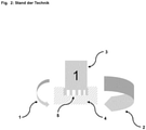
- FIG. 1 shows a schematic representation of a drilling process on a substrate (4), as is known from the prior art.
- this situation is preferably also referred to as the second operating state of the drilling device (3).
- a drill bit is shown as a component of the drill (3), which is placed on a substantially planar or even base (4).
- the reference torque (1) is usually greater than a frictional torque (2), the frictional torque (2) being measured as a measured variable, preferably during operation of the drilling device (3).
- the size of the moments (1, 2) relative to one another is illustrated schematically in the figures by the size of the arrows.
- the proportions of the arrows in the figures indicate schematically the proportions between reference torque (1) and friction torque (2).
- the reference value (1) for the friction is preferably stored in a control device of the drill (3).
- the reference value (1) can also be stored in a control device of an autofeed device (not shown) of the drilling device (3).
- the autofeed device is preferably set up to bring about a forward movement of the drilling device (3) or to generate a feed that can be transmitted to the drilling device (3). Since the actual value (2) of the friction is smaller than the reference value (1), control or regulation of the movement of the drilling device (3) is easily possible in these cases and is also easily managed by conventionally working drilling systems.
- the control or regulation of the movement of the drilling device (3) is made more difficult in the applications that are shown schematically and by way of example in 2 being represented.
- a drilling process is to be started in an existing borehole (5), as is known from the prior art.
- the drill bit of the drill (3) is already in the existing borehole (5) at the beginning of the drilling process.
- the reference torque (1) is smaller than the friction torque (2).
- the high friction torque (2) is due in particular to the wall friction in the existing borehole (5), i.e. to the resistance that the drill bit must overcome during its rotational movement within the borehole (5) in order to break down concrete or remove the concrete core from the Cut out the base (4). Drilling into an existing borehole (5) can be significantly facilitated by the proposed method.
- a possible embodiment of the proposed method and the invention is shown schematically in 3 represents.
- 3 shows 3 a possible course of a drilling process in an existing borehole (5).
- FIG. 3 consists of four individual work situations, which are labeled a) to d) at the top left of the image, starting from sub-figure a).
- the core bit of a drilling device (3) is shown in the center of each of the sub-figures and is intended to continue drilling in an existing borehole (5).
- the reference torque (1) which is shown on the left-hand side of the drill bit in the sub-figures, is significantly smaller than the frictional torque (2) or the measured actual value (2) for the friction of the drill bit in the borehole (5).
- This state can, according to the in Figure 3a ) shown last longer than a period t of 5 s.
- the drilling system can then switch over to normal drilling operation, in which case normal drilling operation can, for example, take place in the same way as drilling on an essentially planar or level subsoil (4).
- normal drilling operation can, for example, take place in the same way as drilling on an essentially planar or level subsoil (4).
- a drilling situation as shown in sub-figure 3b) may exist (see 3 top right).
- a friction torque (2) is determined as a measured variable, which is significantly smaller than the reference value (1) stored in the drilling system.
- the reference torque (1) is greater than the friction torque (2).
- the drill bit of the drill (3) can be driven into the borehole (5). This movement of the drill (3) is preferably effected or controlled by the autofeed device of the drill (3).
- Partial figure 3c) shows the drill bit of the drilling device (3) approaching a drilling surface, i.e. the subsoil (4) to be worked. Partial figure 3c) in particular also shows a working situation in a normal drilling stage of the drilling system.
- the reference torque (1) is greater than the friction torque (2), which preferably corresponds to the actually measured actual value (2) of the friction.
- the friction torque (2) together with a reduction torque can correspond to half of the reference torque (1). In this situation, it is advantageously possible to dismantle concrete and thus work to progress.
- a transition to a situation according to sub-figure 3d) is made possible by switching on the control.
- the drilling system is also in a normal drilling stage in the work situation shown in sub-figure 3d).
- the reference torque (1) is greater than the friction torque (2).
- the reference value (1) in this situation can correspond to the sum of the friction torque (2) and the reduction torque.
- work progress can be achieved by dismantling concrete.
- the switched-on control ensures that the drilling system receives a specification for the rotational speed of the feed speed. In other words, the drilling system can receive a speed specification for the speed of the feed motor of the autofeed device.
Landscapes
- Engineering & Computer Science (AREA)
- Mechanical Engineering (AREA)
- Mining & Mineral Resources (AREA)
- Earth Drilling (AREA)
- Processing Of Stones Or Stones Resemblance Materials (AREA)
Priority Applications (4)
| Application Number | Priority Date | Filing Date | Title |
|---|---|---|---|
| EP20191325.8A EP3957451A1 (fr) | 2020-08-17 | 2020-08-17 | Procédé de perçage amélioré à l'aide d'un appareil de perçage dans un trou de perçage existant et système de perçage |
| PCT/EP2021/071620 WO2022037930A1 (fr) | 2020-08-17 | 2021-08-03 | Procédé pour le démarrage amélioré d'un forage avec un dispositif de forage dans un trou de forage existant et système de forage |
| US18/021,357 US20240033831A1 (en) | 2020-08-17 | 2021-08-03 | Method for improved starting of drilling with a drilling device in an existing borehole, and drilling system |
| EP21752699.5A EP4196328A1 (fr) | 2020-08-17 | 2021-08-03 | Procédé pour le démarrage amélioré d'un forage avec un dispositif de forage dans un trou de forage existant et système de forage |
Applications Claiming Priority (1)
| Application Number | Priority Date | Filing Date | Title |
|---|---|---|---|
| EP20191325.8A EP3957451A1 (fr) | 2020-08-17 | 2020-08-17 | Procédé de perçage amélioré à l'aide d'un appareil de perçage dans un trou de perçage existant et système de perçage |
Publications (1)
| Publication Number | Publication Date |
|---|---|
| EP3957451A1 true EP3957451A1 (fr) | 2022-02-23 |
Family
ID=72139498
Family Applications (2)
| Application Number | Title | Priority Date | Filing Date |
|---|---|---|---|
| EP20191325.8A Withdrawn EP3957451A1 (fr) | 2020-08-17 | 2020-08-17 | Procédé de perçage amélioré à l'aide d'un appareil de perçage dans un trou de perçage existant et système de perçage |
| EP21752699.5A Pending EP4196328A1 (fr) | 2020-08-17 | 2021-08-03 | Procédé pour le démarrage amélioré d'un forage avec un dispositif de forage dans un trou de forage existant et système de forage |
Family Applications After (1)
| Application Number | Title | Priority Date | Filing Date |
|---|---|---|---|
| EP21752699.5A Pending EP4196328A1 (fr) | 2020-08-17 | 2021-08-03 | Procédé pour le démarrage amélioré d'un forage avec un dispositif de forage dans un trou de forage existant et système de forage |
Country Status (3)
| Country | Link |
|---|---|
| US (1) | US20240033831A1 (fr) |
| EP (2) | EP3957451A1 (fr) |
| WO (1) | WO2022037930A1 (fr) |
Citations (4)
| Publication number | Priority date | Publication date | Assignee | Title |
|---|---|---|---|---|
| US3259023A (en) * | 1965-01-08 | 1966-07-05 | Applied Machine Res Inc | Metal working machine and machining process |
| US3475997A (en) * | 1967-03-10 | 1969-11-04 | Giddings & Lewis | Method and apparatus for controlling motions of a drilling cutter or the like |
| EP0339659A2 (fr) * | 1988-04-28 | 1989-11-02 | Fuji Jukogyo Kabushiki Kaisha | Méthode et dispositif pour commander une opération de perçage |
| US20040253064A1 (en) * | 2003-02-01 | 2004-12-16 | Oliver Koslowski | Feed adaptation core drill |
Family Cites Families (12)
| Publication number | Priority date | Publication date | Assignee | Title |
|---|---|---|---|---|
| US5474142A (en) * | 1993-04-19 | 1995-12-12 | Bowden; Bobbie J. | Automatic drilling system |
| SE529230C2 (sv) * | 2004-12-10 | 2007-06-05 | Atlas Copco Rock Drills Ab | Anordning och metod vid borrning i berg |
| GB2466812B (en) * | 2009-01-08 | 2011-10-19 | Schlumberger Holdings | Drillstring dynamics |
| NO338750B1 (no) * | 2009-03-02 | 2016-10-17 | Drilltronics Rig Systems As | Fremgangsmåte og system for automatisert styring av boreprosess |
| US20120186873A1 (en) * | 2009-10-05 | 2012-07-26 | Halliburton Energy Services, Inc. | Well drilling method utilizing real time response to ahead of bit measurements |
| US9784035B2 (en) * | 2015-02-17 | 2017-10-10 | Nabors Drilling Technologies Usa, Inc. | Drill pipe oscillation regime and torque controller for slide drilling |
| EP3087945A1 (fr) * | 2015-04-28 | 2016-11-02 | HILTI Aktiengesellschaft | Détection de surface intelligente et début de carottage |
| FR3058342B1 (fr) * | 2016-11-04 | 2021-01-01 | Seti Tec | Procede de percage comprenant une mesure de trainee(s), et dispositif de percage correspondant |
| US10724358B2 (en) * | 2017-10-11 | 2020-07-28 | Nabors Drilling Technologies Usa, Inc. | Anti-stick-slip systems and methods |
| US11719087B2 (en) * | 2018-08-24 | 2023-08-08 | Nabors Drilling Technologies USA, Ino. | Modeling friction along a wellbore |
| US11512540B2 (en) * | 2019-10-31 | 2022-11-29 | Schlumberger Technology Corporation | Methods for mitigating whirl |
| WO2021252341A1 (fr) * | 2020-06-09 | 2021-12-16 | Magnetic Variation Services LLC | Sondage de profondeur de frottement de puits de forage par oscillation d'un train de tiges ou d'un tubage |
-
2020
- 2020-08-17 EP EP20191325.8A patent/EP3957451A1/fr not_active Withdrawn
-
2021
- 2021-08-03 US US18/021,357 patent/US20240033831A1/en active Pending
- 2021-08-03 EP EP21752699.5A patent/EP4196328A1/fr active Pending
- 2021-08-03 WO PCT/EP2021/071620 patent/WO2022037930A1/fr not_active Ceased
Patent Citations (4)
| Publication number | Priority date | Publication date | Assignee | Title |
|---|---|---|---|---|
| US3259023A (en) * | 1965-01-08 | 1966-07-05 | Applied Machine Res Inc | Metal working machine and machining process |
| US3475997A (en) * | 1967-03-10 | 1969-11-04 | Giddings & Lewis | Method and apparatus for controlling motions of a drilling cutter or the like |
| EP0339659A2 (fr) * | 1988-04-28 | 1989-11-02 | Fuji Jukogyo Kabushiki Kaisha | Méthode et dispositif pour commander une opération de perçage |
| US20040253064A1 (en) * | 2003-02-01 | 2004-12-16 | Oliver Koslowski | Feed adaptation core drill |
Also Published As
| Publication number | Publication date |
|---|---|
| EP4196328A1 (fr) | 2023-06-21 |
| US20240033831A1 (en) | 2024-02-01 |
| WO2022037930A1 (fr) | 2022-02-24 |
Similar Documents
| Publication | Publication Date | Title |
|---|---|---|
| DE102007003080B4 (de) | Unterirdische Bohrmaschine und Verfahren zum Steuern des unterirdischen Bohrens | |
| EP3288717B1 (fr) | Procédé de réglage d'un système de corratage et système de carrotage | |
| DE19708997C2 (de) | Vorrichtung zur Steuerung des Vorschubantriebes einer zum Erzeugen von Erdbohrungen bestimmten Bohranlage | |
| DE2021232B2 (de) | Verfahren und Vorrichtung zur Optimierung des Bohrfortschritts | |
| DE102015105908A1 (de) | Bohrgerät zum Erstellen einer verrohrten Bohrung und Verfahren zum Betreiben eines Bohrgerätes | |
| EP3088150A1 (fr) | Génération adaptative de paramètres de forage lors de carottage automatisé | |
| EP2758675A1 (fr) | Tige d'ancrage | |
| DE102011006015A1 (de) | Gewindeschneidsystem | |
| EP0825329A2 (fr) | Appareil de forage avec un dispositif de contrÔle de l'avance | |
| EP2048383A2 (fr) | Vis autoforeuse | |
| EP1475347B1 (fr) | Ensemble de treuil et procédé pour son fonctionnement | |
| EP3115511A1 (fr) | Procédé de fabrication d'un mur de pieux de perçage superposé | |
| EP3957451A1 (fr) | Procédé de perçage amélioré à l'aide d'un appareil de perçage dans un trou de perçage existant et système de perçage | |
| DE602005003371T2 (de) | Verfahren und system zum bohrlochbeginn | |
| EP3091173A1 (fr) | Installation de forage destinee a produire ou a elargir un forage terrestre dans la terre et procede de commande d'un dispositif d'avance d'une telle installation de forage | |
| EP3848160A1 (fr) | Procédé de fourniture d'une fonction boost pour un outil électrique, ainsi qu'outil électrique pourvu de moteur | |
| EP3792403A1 (fr) | Procédé de fabrication d'un pieu foré à décalage planimétrique plein, système d'aide au vissage permettant de guider un processus de vissage dans un tel procédé ainsi que logiciel pour un tel système d'aide au vissage | |
| EP3919208A1 (fr) | Système de forage comprenant un appareil de carottage et un dispositif d'avance et procédé de détection et d'élimination d'un blocage d'une couronne de carottier | |
| EP1477633A2 (fr) | Procédé et dispositif pour le travail du sol | |
| DE2732117A1 (de) | Verfahren und vorrichtung zum geraeusch- und vibrationsfreien setzen eines pfeilers | |
| DE10002314A1 (de) | Bohrverfahren und dazugehöriges Arbeitsgerät zum Erstellen von Ortbetonbohrpfählen | |
| EP3429788A1 (fr) | Procédé de fonctionnement d'une machine-outil et machine-outil pouvant être actionnée par le procédé | |
| DE19924200A1 (de) | Drehzahl-Vorschubregelung | |
| EP3530871B1 (fr) | Dispositif de production ou d'élargissement d'un forage de sol | |
| DE19936410A1 (de) | Optimieren des Endlosschneckenbohrverfahrens durch eine mitlaufende, bereichsweise vorhandene Verrohrung bzw. ein äußeres Schutzrohr und einer optimal angeordneten Innenschnecke |
Legal Events
| Date | Code | Title | Description |
|---|---|---|---|
| PUAI | Public reference made under article 153(3) epc to a published international application that has entered the european phase |
Free format text: ORIGINAL CODE: 0009012 |
|
| STAA | Information on the status of an ep patent application or granted ep patent |
Free format text: STATUS: THE APPLICATION HAS BEEN PUBLISHED |
|
| AK | Designated contracting states |
Kind code of ref document: A1 Designated state(s): AL AT BE BG CH CY CZ DE DK EE ES FI FR GB GR HR HU IE IS IT LI LT LU LV MC MK MT NL NO PL PT RO RS SE SI SK SM TR |
|
| STAA | Information on the status of an ep patent application or granted ep patent |
Free format text: STATUS: THE APPLICATION IS DEEMED TO BE WITHDRAWN |
|
| 18D | Application deemed to be withdrawn |
Effective date: 20220824 |