EP3961880A1 - Partie active d'une machine électrique pourvue de conducteur imprimé - Google Patents
Partie active d'une machine électrique pourvue de conducteur imprimé Download PDFInfo
- Publication number
- EP3961880A1 EP3961880A1 EP20193655.6A EP20193655A EP3961880A1 EP 3961880 A1 EP3961880 A1 EP 3961880A1 EP 20193655 A EP20193655 A EP 20193655A EP 3961880 A1 EP3961880 A1 EP 3961880A1
- Authority
- EP
- European Patent Office
- Prior art keywords
- electrical conductors
- printed
- electrical
- active part
- intermediate body
- Prior art date
- Legal status (The legal status is an assumption and is not a legal conclusion. Google has not performed a legal analysis and makes no representation as to the accuracy of the status listed.)
- Withdrawn
Links
Images



Classifications
-
- H—ELECTRICITY
- H02—GENERATION; CONVERSION OR DISTRIBUTION OF ELECTRIC POWER
- H02K—DYNAMO-ELECTRIC MACHINES
- H02K15/00—Processes or apparatus specially adapted for manufacturing, assembling, maintaining or repairing of dynamo-electric machines
- H02K15/02—Processes or apparatus specially adapted for manufacturing, assembling, maintaining or repairing of dynamo-electric machines of stator or rotor bodies
- H02K15/021—Magnetic cores
- H02K15/023—Cage rotors
-
- B—PERFORMING OPERATIONS; TRANSPORTING
- B22—CASTING; POWDER METALLURGY
- B22F—WORKING METALLIC POWDER; MANUFACTURE OF ARTICLES FROM METALLIC POWDER; MAKING METALLIC POWDER; APPARATUS OR DEVICES SPECIALLY ADAPTED FOR METALLIC POWDER
- B22F10/00—Additive manufacturing of workpieces or articles from metallic powder
- B22F10/60—Treatment of workpieces or articles after build-up
- B22F10/64—Treatment of workpieces or articles after build-up by thermal means
-
- B—PERFORMING OPERATIONS; TRANSPORTING
- B33—ADDITIVE MANUFACTURING TECHNOLOGY
- B33Y—ADDITIVE MANUFACTURING, i.e. MANUFACTURING OF THREE-DIMENSIONAL [3D] OBJECTS BY ADDITIVE DEPOSITION, ADDITIVE AGGLOMERATION OR ADDITIVE LAYERING, e.g. BY 3D PRINTING, STEREOLITHOGRAPHY OR SELECTIVE LASER SINTERING
- B33Y40/00—Auxiliary operations or equipment, e.g. for material handling
- B33Y40/20—Post-treatment, e.g. curing, coating or polishing
-
- H—ELECTRICITY
- H02—GENERATION; CONVERSION OR DISTRIBUTION OF ELECTRIC POWER
- H02K—DYNAMO-ELECTRIC MACHINES
- H02K15/00—Processes or apparatus specially adapted for manufacturing, assembling, maintaining or repairing of dynamo-electric machines
- H02K15/04—Processes or apparatus specially adapted for manufacturing, assembling, maintaining or repairing of dynamo-electric machines of windings prior to their mounting into the machines
- H02K15/0407—Manufacturing of windings by etching, printing or stamping the complete coils
-
- H—ELECTRICITY
- H02—GENERATION; CONVERSION OR DISTRIBUTION OF ELECTRIC POWER
- H02K—DYNAMO-ELECTRIC MACHINES
- H02K17/00—Asynchronous induction motors; Asynchronous induction generators
- H02K17/02—Asynchronous induction motors
- H02K17/16—Asynchronous induction motors having rotors with internally short-circuited windings, e.g. cage rotors
-
- H—ELECTRICITY
- H02—GENERATION; CONVERSION OR DISTRIBUTION OF ELECTRIC POWER
- H02K—DYNAMO-ELECTRIC MACHINES
- H02K17/00—Asynchronous induction motors; Asynchronous induction generators
- H02K17/02—Asynchronous induction motors
- H02K17/16—Asynchronous induction motors having rotors with internally short-circuited windings, e.g. cage rotors
- H02K17/168—Asynchronous induction motors having rotors with internally short-circuited windings, e.g. cage rotors having single-cage rotors
-
- H—ELECTRICITY
- H02—GENERATION; CONVERSION OR DISTRIBUTION OF ELECTRIC POWER
- H02K—DYNAMO-ELECTRIC MACHINES
- H02K17/00—Asynchronous induction motors; Asynchronous induction generators
- H02K17/02—Asynchronous induction motors
- H02K17/16—Asynchronous induction motors having rotors with internally short-circuited windings, e.g. cage rotors
- H02K17/18—Asynchronous induction motors having rotors with internally short-circuited windings, e.g. cage rotors having double-cage or multiple-cage rotors
-
- H—ELECTRICITY
- H02—GENERATION; CONVERSION OR DISTRIBUTION OF ELECTRIC POWER
- H02K—DYNAMO-ELECTRIC MACHINES
- H02K17/00—Asynchronous induction motors; Asynchronous induction generators
- H02K17/02—Asynchronous induction motors
- H02K17/16—Asynchronous induction motors having rotors with internally short-circuited windings, e.g. cage rotors
- H02K17/20—Asynchronous induction motors having rotors with internally short-circuited windings, e.g. cage rotors having deep-bar rotors
-
- H—ELECTRICITY
- H02—GENERATION; CONVERSION OR DISTRIBUTION OF ELECTRIC POWER
- H02K—DYNAMO-ELECTRIC MACHINES
- H02K3/00—Details of windings
- H02K3/04—Windings characterised by the conductor shape, form or construction, e.g. with bar conductors
- H02K3/26—Windings characterised by the conductor shape, form or construction, e.g. with bar conductors consisting of printed conductors
-
- B—PERFORMING OPERATIONS; TRANSPORTING
- B22—CASTING; POWDER METALLURGY
- B22F—WORKING METALLIC POWDER; MANUFACTURE OF ARTICLES FROM METALLIC POWDER; MAKING METALLIC POWDER; APPARATUS OR DEVICES SPECIALLY ADAPTED FOR METALLIC POWDER
- B22F2998/00—Supplementary information concerning processes or compositions relating to powder metallurgy
- B22F2998/10—Processes characterised by the sequence of their steps
-
- B—PERFORMING OPERATIONS; TRANSPORTING
- B33—ADDITIVE MANUFACTURING TECHNOLOGY
- B33Y—ADDITIVE MANUFACTURING, i.e. MANUFACTURING OF THREE-DIMENSIONAL [3D] OBJECTS BY ADDITIVE DEPOSITION, ADDITIVE AGGLOMERATION OR ADDITIVE LAYERING, e.g. BY 3D PRINTING, STEREOLITHOGRAPHY OR SELECTIVE LASER SINTERING
- B33Y80/00—Products made by additive manufacturing
-
- Y—GENERAL TAGGING OF NEW TECHNOLOGICAL DEVELOPMENTS; GENERAL TAGGING OF CROSS-SECTIONAL TECHNOLOGIES SPANNING OVER SEVERAL SECTIONS OF THE IPC; TECHNICAL SUBJECTS COVERED BY FORMER USPC CROSS-REFERENCE ART COLLECTIONS [XRACs] AND DIGESTS
- Y02—TECHNOLOGIES OR APPLICATIONS FOR MITIGATION OR ADAPTATION AGAINST CLIMATE CHANGE
- Y02P—CLIMATE CHANGE MITIGATION TECHNOLOGIES IN THE PRODUCTION OR PROCESSING OF GOODS
- Y02P10/00—Technologies related to metal processing
- Y02P10/25—Process efficiency
Definitions
- the invention relates to an active part of an electrical machine and a method for producing it.
- An electrical machine has a stator and a rotor. If the electrical machine is an asynchronous machine, both the stator and the rotor are energized during operation of the electrical machine.
- the rotor is therefore also an active part of the electric machine, since it has a squirrel cage which has conductors through which electric current flows during operation of the electric machine.
- the rotor of the electrical machine i.e. the active part of the asynchronous machine which rotates during operation, is exposed to centrifugal forces during operation.
- Conductors of the active part i.e. in particular conductors of the squirrel cage, must be designed or constructed in such a way that they withstand the centrifugal forces.
- a specific problem is, for example, a connection (e.g. for the production of components for electrical machines, such as the rotor of an asynchronous machine as its active part) using different materials (e.g. copper / iron or copper / steel or iron / steel) run stably. This is achieved, for example, by material connections.
- Such an integral connection was previously made, for example, for squirrel-cage rotors of asynchronous machines.
- the rotor of high-speed drives is made of solid, high-strength steel with an integrated short-circuit rotor winding.
- grooves for the rods or the ring segments of the winding are first milled or turned in the solid rotor body and then solid, nickel-plated copper rods/ring segments inserted.
- HIP Hot Isostatic Pressing
- One object of the invention is to design an active part of the electrical machine, in particular a rotor of the electrical machine, in a simple and stable manner. This is to ensure that the active part is not destroyed during rotation.
- a solution to the problem results from an active part according to claim 1.
- a further solution to the problem results from a method according to claim 8. Further configurations result from claims 2 to 7 and 9 to 12.
- An active part of an electrical machine which has electrical conductors, has electrical conductors that are printed.
- the active part of the electrical machine is in particular a rotor of the electrical machine.
- the electrical machine is in particular an asynchronous machine.
- the printed electrical conductor is in particular a conductor of a squirrel cage of the asynchronous machine.
- the intermediate bodies have a different and lower electrical conductivity than the electrical conductors. By printing the electrical conductors, a firm connection can be made.
- the printed electrical conductors have a longitudinal orientation parallel to the axis of rotation of the rotor. For example, copper and/or aluminum can be used for the printed electrical conductor.
- electrical conductors are printed, as are intermediate bodies between the electrical conductors. This also increases strength.
- the electrical conductors are positioned symmetrically over the circumference of the rotor (active part).
- At least one of the electrical conductors has a cross section in a section that tapers with increasing radius.
- the radius relates to the axis of rotation of the active part (rotor).
- the cross section tapers radially outwards, the printed electrical conductor can still be held on adjacent intermediate bodies. This results from the geometric shape when the intermediate bodies are each directly or indirectly connected to the electrical conductors in the circumferential direction.
- An indirect connection results, for example, when there is an intermediate layer between the electrical conductor and the intermediate body. This is, for example, made of a material which has means.
- the intermediate bodies are made, for example, from a material that includes steel and/or iron. If the cross section of a printed electrical conductor tapers, it tapers in particular in a tangential direction. The cross section results from an end view of the electrical conductors or the intermediate bodies.
- the cross section alternately increases and decreases or decreases and increases radially outwards in its tangential extent. This also applies to the cross section with regard to the tangential extension of the intermediate bodies.
- the result is that where the cross section of the printed electrical conductor tapers in a radial direction, the cross section of the intermediate body increases in a corresponding manner and vice versa. This results in particular in an interlocking of electrical Conductors and intermediate bodies, the intermediate body can also be printed.
- the active part it can consequently be designed in such a way that at least one of the electrical conductors has a multiplicity of sections with cross sections which taper with increasing radius.
- the sections correspond, for example, at least in part to sections of a print of the electrical conductors, with the electrical conductors being printed on alternately to the intermediate body, increasing radially.
- a three-dimensional structure is formed between at least one of the printed electrical conductors and the printed intermediate body.
- This three-dimensional structure is jagged or wavy in cross section, for example. This results in a form fit between the intermediate body and the electrical conductors so that they can be held in position better, even when forces act on them radially outwards.
- the three-dimensional structure thus has a jagged pattern or a wave pattern in a cross section.
- the electrical conductivity of the electrical conductors differs radially.
- the electrical conductivity is particularly greater in areas that have a larger radius, i. H. have a greater distance from the axis of rotation. In this way, the resistance of the electrical conductors can be adjusted and the skin effect can also be taken into account. For example, the electrical conductivity can also decrease radially outwards.
- the electrical conductors and/or the particularly printed intermediate bodies between two of the electrical conductors have layers which end or begin radially there, at which the thickness of a of the electrical conductor or intermediate body has a local minimum or maximum.
- the layering results from the fact that the electrical conductors or the intermediate bodies are printed in layers radially outward.
- the radial thickness of the electrical conductors and the intermediate body thus increases alternately (alternately). This makes it possible to produce the wave shape or jagged shape, which gives additional support.
- an active part in particular a rotor with a squirrel cage, of an electrical machine
- the electrical conductors are printed, with an intermediate body being printed between electrical conductors, with the printing of at least one electrical conductor and an intermediate body being alternated.
- the squirrel-cage cage of the active part (rotor) of the asynchronous machine must be manufactured additively in such a way that a material bond is created between the materials.
- the material connection is necessary in order to be able to guarantee high strength in the interface of the connection, and thus between the materials. This is achieved, for example, by means of a cold gas spraying process.
- the cold gas spraying process can be used to print electrically conductive material such as copper or aluminum, but also magnetizable material such as iron.
- the squirrel-cage cage of the asynchronous machine can therefore be produced partially or completely using an additive printing process such as "cold gas spraying".
- the conductor material e.g. copper or aluminum
- a soft magnetic material e.g. FeSi2.9
- the conductor material e.g. copper or aluminum
- a soft magnetic material e.g. FeSi2.9
- a third material e.g. nickel
- This additional layer serves to form a diffusion zone.
- the diffusion zone increases the bonding between the adjacent ones Materials.
- the tooth is an example of an intermediate body between the electrical conductors that form short-circuited windings.
- a diffusion zone is then formed in particular between the conductor material and the diffusion layer, between the diffusion layer and the soft magnetic material and between the diffusion layer and the steel of the massive rotor, and thus a high-strength connection between the different materials. It may be necessary for process engineering and/or accuracy reasons to carry out subtractive intermediate processing between the additively built materials.
- the method or methods described are not exclusively limited to asynchronous machines with solid rotors. Rotors can also be made partially solid, for example.
- a first electrical conductor and a second adjacent electrical conductor are printed in one method step, with their width decreasing, with the intermediate body between the first electrical conductor and the second electrical conductor being printed in a subsequent method step, with its width increasing . This results in different thicknesses of the cross sections of the printed elements.
- the electrical conductors and/or the intermediate bodies are printed onto a corrugated body.
- this is constructed so massively that it is unaffected by centrifugal forces that occur.
- printing of at least part of one of the electrical conductors, which is a first printed object, and printing of at least part of the intermediate bodies, which are a second printed object, are alternated in such a way that before a change, a radial increase in thickness of the electrical Conductor or the intermediate body results in the between larger is equal to 50% and less than or equal to 200% of the subsequent radial increase in thickness of the other printed object in each case.
- the method described simplifies production and significantly increases the degree of automation (>80% possible) compared to the existing joining/HIP process.
- it implies the possibility of realizing individual rotor geometries, adapted to special customer requirements (rotor bar geometries), which cannot be produced with conventional methods or can only be produced with extremely great effort.
- a rotor bar i.e. an electrical conductor of the active part, can be given special electrical material properties locally, such as different electrical conductivities.
- the representation after figure 1 shows an electrical machine 10 which has an active part 1 and a stator 2 .
- the active part 1 is a rotor of the electrical machine 10.
- the rotor can be the first active part and the stator can be the second active part be designated.
- the stator 2 has windings with end windings 13 .
- the rotor ie the active part 1 in the present example, is a squirrel-cage rotor. There is an air gap 15 between the stator and the rotor.
- the active part 1 has a first short-circuit ring 11 and a second short-circuit ring 11 ' .
- the active part 1 is rotatably mounted about an axis of rotation 14 .
- the squirrel cage has electrical conductors which are located in a pressure layer 22 .
- the electrical conductors are printed on a shaft body 6.
- the active part 1 has a radial extension with a radius 7 .
- the pressure layer 22 is located in a radially outer area of the active part 1.
- the electrical conductors of the squirrel cage are in figure 1 not explicitly shown, but run in an axial direction approximately parallel to the axis of rotation 14.
- figure 2 shows different designs of electrical conductors 3,3 ' , 3 " in grooves.
- figure 2 shows an electrical conductor 3 with a constant copper alloy. This is suitable for starting the electrical machine without special requirements.
- figure 2 1 also shows an electrical conductor 3 ' in which an arrow 8 indicates that the conductivity decreases radially outward. This can be achieved, for example, by an alloy with CuSi. Higher conductivities can be achieved, for example, with an E-Cu alloy.
- a change in the conductivity can be used to react to increased requirements with regard to the start-up of the electrical machine.
- the transition of the alloy does not necessarily have to be continuous.
- a sudden change in the conductivity is also possible, for example, as is symbolized by the dotted line 12 in the electrical conductor 3 ′′ .
- figure 3 shows different cross-sectional shapes of electrical conductors.
- a rectangular cross-section is selected.
- the following cross sections are shown from left to right: round bar cross section, high bar cross section, wedge bar cross section and double bar cross section with start-up and operating cage. With the cold spray process, different standard rod shapes with locally different electrical conductivity can be realized.
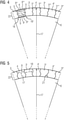
- the representation after figure 4 shows the positioning of the electrical conductors and intermediate pieces in a section of the active part in a front cross-section in the form of a piece of cake.
- the intermediate bodies 4,4 ' , 4 " , 4"' are located between the electrical conductors 3,3 ' , 3 " , 3 '' ' .
- the electrical conductors contain, in particular, copper.
- the intermediate bodies include, in particular, iron and/or steel. Both are printed.
- contact layers 5, 5 ' , 5 " , 5 ''' which in particular contain nickel.
- the contact layers have a serrated pattern 16, 16 ' .
- the electrical conductors and the intermediate bodies are printed on a shaft body Printing takes place from the inside to the outside, which is illustrated by the radial direction 17.
- the width 9.9 ′ , 9 ′′ , 9 ′′′ of the electrical conductors changes outwards in the circumferential direction.
- the width of the intermediate bodies also changes in the same radial position.
- the jagged shape results in a particularly good hold within a pressure layer 22 .
- FIG 5 shows in a similar way as figure 4 the cross section of a section of an active part, the boundary area between the electrical conductors and the intermediate body not being shown, but running in a wavy manner.
- the representation according to Figures 6 to 9 shows the sequence of printing operations.
- a layer of the electrical conductors 3,3 ' ,3 " ,3 “' is printed onto the shaft body 6. These electrical conductors are spaced apart from one another.
- layers of the intermediate bodies 4,4 ' ,4 " ,4 ''' printed, extending radially outward over the first layer of electrical conductors result.
- the electrical conductors are then printed in layers so that they also rise radially outwards over the intermediate bodies. This results in levels 20.
- step 9 the intermediate bodies are then initially printed further radially outwards until the electrical conductors are then printed outwards in such a way that there are no longer any steps.
- This step-by-step procedure forms layers 19, 19 ' .
- the representation according to Figures 10 to 13 shows the sequence of printing processes, according to that already in the Figures 6 to 9 shown sequence.
- the electrical conductors have a rounded shape and reflect how electrical conductors and intermediate bodies can be connected to one another through their shape in order to absorb centrifugal forces. It is shown that here too the width 18 of a formed electrical conductor changes alternately radially outwards, ie once larger it becomes smaller again and then larger again or vice versa.
Landscapes
- Engineering & Computer Science (AREA)
- Power Engineering (AREA)
- Manufacturing & Machinery (AREA)
- Chemical & Material Sciences (AREA)
- Materials Engineering (AREA)
- Physics & Mathematics (AREA)
- Thermal Sciences (AREA)
- Manufacture Of Motors, Generators (AREA)
Priority Applications (5)
| Application Number | Priority Date | Filing Date | Title |
|---|---|---|---|
| EP20193655.6A EP3961880A1 (fr) | 2020-08-31 | 2020-08-31 | Partie active d'une machine électrique pourvue de conducteur imprimé |
| PCT/EP2021/073442 WO2022043353A1 (fr) | 2020-08-31 | 2021-08-25 | Partie active d'une machine électrique comportant un conducteur imprimé |
| CN202180073891.1A CN116458045A (zh) | 2020-08-31 | 2021-08-25 | 电机的具有打印的导体的有源部件 |
| US18/023,627 US11804756B2 (en) | 2020-08-31 | 2021-08-25 | Active part of an electric machine, having a printed conductor |
| EP21769387.8A EP4183033B1 (fr) | 2020-08-31 | 2021-08-25 | Partie active d'une machine électrique pourvue de conducteur imprimé |
Applications Claiming Priority (1)
| Application Number | Priority Date | Filing Date | Title |
|---|---|---|---|
| EP20193655.6A EP3961880A1 (fr) | 2020-08-31 | 2020-08-31 | Partie active d'une machine électrique pourvue de conducteur imprimé |
Publications (1)
| Publication Number | Publication Date |
|---|---|
| EP3961880A1 true EP3961880A1 (fr) | 2022-03-02 |
Family
ID=72292400
Family Applications (2)
| Application Number | Title | Priority Date | Filing Date |
|---|---|---|---|
| EP20193655.6A Withdrawn EP3961880A1 (fr) | 2020-08-31 | 2020-08-31 | Partie active d'une machine électrique pourvue de conducteur imprimé |
| EP21769387.8A Active EP4183033B1 (fr) | 2020-08-31 | 2021-08-25 | Partie active d'une machine électrique pourvue de conducteur imprimé |
Family Applications After (1)
| Application Number | Title | Priority Date | Filing Date |
|---|---|---|---|
| EP21769387.8A Active EP4183033B1 (fr) | 2020-08-31 | 2021-08-25 | Partie active d'une machine électrique pourvue de conducteur imprimé |
Country Status (4)
| Country | Link |
|---|---|
| US (1) | US11804756B2 (fr) |
| EP (2) | EP3961880A1 (fr) |
| CN (1) | CN116458045A (fr) |
| WO (1) | WO2022043353A1 (fr) |
Families Citing this family (1)
| Publication number | Priority date | Publication date | Assignee | Title |
|---|---|---|---|---|
| DE102023103204A1 (de) * | 2023-02-09 | 2024-08-14 | Additive | Drives GmbH | Verfahren zum Herstellen eines Läufers und/oder Rotors sowie Läufer und/oder Rotor und elektrische Maschine |
Citations (3)
| Publication number | Priority date | Publication date | Assignee | Title |
|---|---|---|---|---|
| DE102012006248A1 (de) * | 2011-04-04 | 2012-10-04 | Fanuc Corporation | Kurzschlussläufer und dessen Herstellungsverfahren |
| JP2014108006A (ja) * | 2012-11-29 | 2014-06-09 | Toyota Industries Corp | 回転子、その回転子を備える誘導電動機、及び回転子の製造方法 |
| EP3629452A1 (fr) * | 2018-09-28 | 2020-04-01 | Siemens Aktiengesellschaft | Procédé de fabrication d'un rotor pour une machine à rotation électrique |
Family Cites Families (29)
| Publication number | Priority date | Publication date | Assignee | Title |
|---|---|---|---|---|
| US3456144A (en) * | 1962-09-20 | 1969-07-15 | Printed Motors Inc | Printed-circuit multilayer winding for electric rotary machines |
| DE2409681A1 (de) * | 1974-02-28 | 1975-09-11 | Retobobina Handelsanstalt | Elektrische ankerwicklung |
| DE19919899C1 (de) * | 1999-03-15 | 2000-09-07 | Loher Ag | Kurzschlußkäfig für eine elektrische Maschine, vorzugsweise Asynchronmaschine |
| PT1590871E (pt) * | 2003-02-07 | 2008-08-27 | Core Motion Inc | Dispositivo energético rotativo de campo axial de condutor optimizado |
| EP2333133B1 (fr) * | 2009-11-23 | 2013-03-06 | Linde Aktiengesellschaft | Procédé de fabrication d'une bobine multicouche |
| US8701270B2 (en) * | 2010-01-21 | 2014-04-22 | GM Global Technology Operations LLC | Methods of manufacturing induction rotors with conductor bars having high conductivity |
| NL2011129C2 (nl) * | 2013-07-09 | 2015-01-12 | Eco Logical Entpr B V | Compacte elektrische inrichting en daarop gebaseerde elektrodynamische luidspreker, elektromotor, roerinrichting en instelbare koppeling. |
| EP2999092A1 (fr) * | 2014-09-18 | 2016-03-23 | ABB Technology AG | Isolation d'un conducteur bobinés et procédé d'isolation un tel conducteur |
| US10170953B2 (en) * | 2015-10-02 | 2019-01-01 | E-Circuit Motors, Inc. | Planar composite structures and assemblies for axial flux motors and generators |
| US9673684B2 (en) * | 2015-10-02 | 2017-06-06 | E-Circuit Motors, Inc. | Structures and methods for thermal management in printed circuit board stators |
| EP3255758A1 (fr) | 2016-06-07 | 2017-12-13 | Siemens Aktiengesellschaft | Rotor pour une machine a reluctance |
| EP3288159A1 (fr) * | 2016-08-24 | 2018-02-28 | Siemens Aktiengesellschaft | Rotor en court-circuit en particulier pour dispositifs a haut regime |
| EP3297131A1 (fr) | 2016-09-19 | 2018-03-21 | Siemens Aktiengesellschaft | Stator pour une machine rotative electrique |
| EP3301794A1 (fr) * | 2016-09-30 | 2018-04-04 | Siemens Aktiengesellschaft | Fabrication d'un rotor de machine electrique rotative |
| EP3493371A1 (fr) * | 2017-11-30 | 2019-06-05 | Siemens Aktiengesellschaft | Rotor en cage d'écureuil renforcé |
| EP3518398A1 (fr) * | 2018-01-30 | 2019-07-31 | Siemens Aktiengesellschaft | Bague terminale courte pour raccordement avec les barres de cage |
| DE102018208409A1 (de) * | 2018-05-28 | 2019-11-28 | Thyssenkrupp Ag | Kurzschlussläufer für einen Elektromotor, insbesondere Asynchronmotor, Elektromotor, sowie Verfahren zur Herstellung eines Kurzschlussrings eines Kurzschlussläufers |
| EP3576256A1 (fr) * | 2018-05-29 | 2019-12-04 | Siemens Aktiengesellschaft | Conduite électrique à structure en grille et procédé de fabrication |
| EP3595146A1 (fr) * | 2018-07-12 | 2020-01-15 | Siemens Aktiengesellschaft | Rotor à cage en court-circuit, procédé de fabrication |
| EP3618232A1 (fr) * | 2018-08-30 | 2020-03-04 | Siemens Aktiengesellschaft | Machine électrique, procédé de fabrication d'une machine électrique et véhicule électrique |
| GB2577288A (en) * | 2018-09-20 | 2020-03-25 | Rolls Royce Plc | Electrical machine winding assembly and method of manufacture thereof |
| JP7293627B2 (ja) * | 2018-12-05 | 2023-06-20 | 株式会社デンソー | 回転電機及び回転電機の製造方法 |
| EP3723244A1 (fr) * | 2019-04-08 | 2020-10-14 | Siemens Aktiengesellschaft | Agencement de tête d'enroulement pour une machine rotative électrique |
| US11283319B2 (en) * | 2019-11-11 | 2022-03-22 | Infinitum Electric, Inc. | Axial field rotary energy device with PCB stator having interleaved PCBS |
| US12040317B2 (en) * | 2019-12-06 | 2024-07-16 | Osram Opto Semiconductors Gmbh | Optoelectronic device |
| DE102021102753B4 (de) * | 2021-02-05 | 2023-05-25 | Ford Global Technologies Llc | Elektrische Maschine |
| JP7594967B2 (ja) * | 2021-04-12 | 2024-12-05 | Tdk株式会社 | コイル型電子部品 |
| DE102022119376A1 (de) * | 2021-08-06 | 2023-02-09 | Ford Global Technologies, Llc | Elektroblech für eine elektrische Maschine sowie Verfahren zur Herstellung eines Elektroblechs |
| EP4181637A1 (fr) * | 2021-11-15 | 2023-05-17 | AT & S Austria Technologie & Systemtechnik Aktiengesellschaft | Support de composant comportant un trou d'interconnexion contenant un matériau de remplissage durci |
-
2020
- 2020-08-31 EP EP20193655.6A patent/EP3961880A1/fr not_active Withdrawn
-
2021
- 2021-08-25 CN CN202180073891.1A patent/CN116458045A/zh active Pending
- 2021-08-25 US US18/023,627 patent/US11804756B2/en active Active
- 2021-08-25 WO PCT/EP2021/073442 patent/WO2022043353A1/fr not_active Ceased
- 2021-08-25 EP EP21769387.8A patent/EP4183033B1/fr active Active
Patent Citations (3)
| Publication number | Priority date | Publication date | Assignee | Title |
|---|---|---|---|---|
| DE102012006248A1 (de) * | 2011-04-04 | 2012-10-04 | Fanuc Corporation | Kurzschlussläufer und dessen Herstellungsverfahren |
| JP2014108006A (ja) * | 2012-11-29 | 2014-06-09 | Toyota Industries Corp | 回転子、その回転子を備える誘導電動機、及び回転子の製造方法 |
| EP3629452A1 (fr) * | 2018-09-28 | 2020-04-01 | Siemens Aktiengesellschaft | Procédé de fabrication d'un rotor pour une machine à rotation électrique |
Also Published As
| Publication number | Publication date |
|---|---|
| US20230246527A1 (en) | 2023-08-03 |
| EP4183033B1 (fr) | 2024-09-25 |
| US11804756B2 (en) | 2023-10-31 |
| WO2022043353A1 (fr) | 2022-03-03 |
| CN116458045A (zh) | 2023-07-18 |
| EP4183033A1 (fr) | 2023-05-24 |
Similar Documents
| Publication | Publication Date | Title |
|---|---|---|
| EP2577852B1 (fr) | Induit à cage d'écureuil pour une machine asynchrone et procédé de fabrication de l'induit à cage d'écureuil | |
| EP3178155A1 (fr) | Rotor, machine à réluctance et procédé de fabrication d'un rotor | |
| EP3178152A1 (fr) | Rotor et machine à reluctance | |
| EP3867998B1 (fr) | Assemblage d'un empilage de tôles sur un arbre | |
| DE2521557A1 (de) | Induktionsmotor mit einem zahlreiche kaefiganordnungen aufweisenden rotor und verfahren zur herstellung | |
| EP3082227A1 (fr) | Rotor d'une machine asynchrone | |
| DE102015204872A1 (de) | Käfigläufer für eine elektrische Asynchronmaschine mit einen Kurzschlussring stabilisierenden Zugankern | |
| EP3205004B1 (fr) | Rotor à cage destiné à un moteur électrique asynchrone, muni d'un disque de support stabilisant la bague de court-circuit | |
| EP4183033B1 (fr) | Partie active d'une machine électrique pourvue de conducteur imprimé | |
| EP2820746B1 (fr) | Induit à cage d'écureuil pour micromoteur et son procédé de fabrication | |
| EP3554730B1 (fr) | Procédé de cintrage de profilés extrudés | |
| EP4029133B1 (fr) | Rotor à cage d'écureuil et son procédé de fabrication | |
| EP3393016A1 (fr) | Procédé de fabrication d'un rotor à court-circuit et rotor à court-circuit | |
| WO2019228951A1 (fr) | Rotor en court-circuit pour moteur électrique, en particulier pour moteur asynchrone, moteur électrique et procédé de fabrication d'un rotor en court-circuit | |
| WO2024213692A1 (fr) | Enroulement pour un rotor cylindrique, en particulier un rotor à pôles saillants, rotor comprenant l'enroulement, et machine électrique comprenant le rotor et l'enroulement | |
| DE102015202004A1 (de) | Käfigläuferrotor mit stabilem Kurzschlussring für eine elektrische Asynchronmaschine sowie Verfahren zum Fertigen desselben | |
| DE102018208409A1 (de) | Kurzschlussläufer für einen Elektromotor, insbesondere Asynchronmotor, Elektromotor, sowie Verfahren zur Herstellung eines Kurzschlussrings eines Kurzschlussläufers | |
| EP3657635A1 (fr) | Rotor pour une machine asynchrone à géométrie de type barre optimisée en termes de pertes, machine asynchrone ainsi que procédé | |
| EP4277096A1 (fr) | Rotor d'un moteur à rotor à cage d'écureuil et son procédé de fabrication | |
| EP4436015A1 (fr) | Rotor d'un moteur à cage d'écureuil, moteur à cage d'écureuil comprenant un rotor et procédé de fabrication d'un rotor d'un moteur à cage d'écureuil | |
| EP3425779A1 (fr) | Induit à cage d'écureuil d'une machine asynchrone | |
| WO2017194271A1 (fr) | Corps de rotor et procédé de fabrication d'un corps de rotor | |
| DE4302901A1 (en) | Core structure for dynamo machine - has arc core segments with front and back magnetic yokes connected along line such that front yoke has number of teeth | |
| DE102024123669A1 (de) | Induktionsmotor mit verstärkten kurzschlussringen | |
| WO2021043365A1 (fr) | Procédé de fabrication de rotor, rotor et moteur asynchrone |
Legal Events
| Date | Code | Title | Description |
|---|---|---|---|
| PUAI | Public reference made under article 153(3) epc to a published international application that has entered the european phase |
Free format text: ORIGINAL CODE: 0009012 |
|
| STAA | Information on the status of an ep patent application or granted ep patent |
Free format text: STATUS: THE APPLICATION HAS BEEN PUBLISHED |
|
| AK | Designated contracting states |
Kind code of ref document: A1 Designated state(s): AL AT BE BG CH CY CZ DE DK EE ES FI FR GB GR HR HU IE IS IT LI LT LU LV MC MK MT NL NO PL PT RO RS SE SI SK SM TR |
|
| STAA | Information on the status of an ep patent application or granted ep patent |
Free format text: STATUS: THE APPLICATION IS DEEMED TO BE WITHDRAWN |
|
| 18D | Application deemed to be withdrawn |
Effective date: 20220903 |