EP3971484A1 - Procédé de production d'eau chaude dans un bâtiment, installation de production d'eau chaude et dispositif de commande d'une installation de production d'eau chaude - Google Patents
Procédé de production d'eau chaude dans un bâtiment, installation de production d'eau chaude et dispositif de commande d'une installation de production d'eau chaude Download PDFInfo
- Publication number
- EP3971484A1 EP3971484A1 EP21181483.5A EP21181483A EP3971484A1 EP 3971484 A1 EP3971484 A1 EP 3971484A1 EP 21181483 A EP21181483 A EP 21181483A EP 3971484 A1 EP3971484 A1 EP 3971484A1
- Authority
- EP
- European Patent Office
- Prior art keywords
- heat
- hot water
- temperature
- heat source
- phase
- Prior art date
- Legal status (The legal status is an assumption and is not a legal conclusion. Google has not performed a legal analysis and makes no representation as to the accuracy of the status listed.)
- Granted
Links
Images


Classifications
-
- F—MECHANICAL ENGINEERING; LIGHTING; HEATING; WEAPONS; BLASTING
- F24—HEATING; RANGES; VENTILATING
- F24D—DOMESTIC- OR SPACE-HEATING SYSTEMS, e.g. CENTRAL HEATING SYSTEMS; DOMESTIC HOT-WATER SUPPLY SYSTEMS; ELEMENTS OR COMPONENTS THEREFOR
- F24D19/00—Details
- F24D19/10—Arrangement or mounting of control or safety devices
- F24D19/1006—Arrangement or mounting of control or safety devices for water heating systems
- F24D19/1051—Arrangement or mounting of control or safety devices for water heating systems for domestic hot water
- F24D19/1063—Arrangement or mounting of control or safety devices for water heating systems for domestic hot water counting of energy consumption
-
- F—MECHANICAL ENGINEERING; LIGHTING; HEATING; WEAPONS; BLASTING
- F24—HEATING; RANGES; VENTILATING
- F24D—DOMESTIC- OR SPACE-HEATING SYSTEMS, e.g. CENTRAL HEATING SYSTEMS; DOMESTIC HOT-WATER SUPPLY SYSTEMS; ELEMENTS OR COMPONENTS THEREFOR
- F24D17/00—Domestic hot-water supply systems
- F24D17/0026—Domestic hot-water supply systems with conventional heating means
- F24D17/0031—Domestic hot-water supply systems with conventional heating means with accumulation of the heated water
-
- F—MECHANICAL ENGINEERING; LIGHTING; HEATING; WEAPONS; BLASTING
- F24—HEATING; RANGES; VENTILATING
- F24D—DOMESTIC- OR SPACE-HEATING SYSTEMS, e.g. CENTRAL HEATING SYSTEMS; DOMESTIC HOT-WATER SUPPLY SYSTEMS; ELEMENTS OR COMPONENTS THEREFOR
- F24D19/00—Details
- F24D19/10—Arrangement or mounting of control or safety devices
- F24D19/1006—Arrangement or mounting of control or safety devices for water heating systems
- F24D19/1066—Arrangement or mounting of control or safety devices for water heating systems for the combination of central heating and domestic hot water
- F24D19/1081—Arrangement or mounting of control or safety devices for water heating systems for the combination of central heating and domestic hot water counting of energy consumption
-
- F—MECHANICAL ENGINEERING; LIGHTING; HEATING; WEAPONS; BLASTING
- F24—HEATING; RANGES; VENTILATING
- F24D—DOMESTIC- OR SPACE-HEATING SYSTEMS, e.g. CENTRAL HEATING SYSTEMS; DOMESTIC HOT-WATER SUPPLY SYSTEMS; ELEMENTS OR COMPONENTS THEREFOR
- F24D3/00—Hot-water central heating systems
- F24D3/08—Hot-water central heating systems in combination with systems for domestic hot-water supply
Definitions
- the invention relates to a method for preparing hot water in a building, a particularly central hot water preparation system used for this purpose, with a heat source, a heat accumulator and a charging circuit for transferring heat from the heat source to the heat accumulator, and a control device for this.
- the hot water is heated in a heating phase in which heat is transferred from the heat source to the heat accumulator and in which the heat source generates heat at least temporarily.
- the hot water is typically heated in the heat accumulator and made available there for consumers. For this purpose, the heated water can be kept ready directly in the heat storage tank, i.e. for removal from the heat storage tank.
- the heat accumulator can also be a buffer accumulator that is used for hot water preparation, for example the heat accumulator of a fresh water station or a hygiene accumulator that stores heated heating water and in which the hot water is heated using the continuous flow principle.
- Water heating can be combined with space heating or stand alone.
- the buildings can be, for example, residential or commercial buildings.
- heat is understood in this text as thermal energy, in particular in the sense of a heated heat carrier, through which the heat can be transferred from the heat source to the heat accumulator.
- the heat source of the (related to the building) particularly central water heating system can be a boiler, the burner of which generates thermal energy, a heat pump, which increases ambient heat from a low level to a level required for hot water preparation, a district or local heating station, which generates thermal energy from a heating network relates or any other entity that is suitable for heating a heat carrier, such as a solar collector.
- a provision of heat by the heat source is also referred to in this text as generating heat and is expressly intended to include cases in which the heat is not generated by an active process but is made available by the heat source, e.g. by the heat source generating the heat through a district or local heating network or solar collectors.
- the invention is independent of the way in which heat is generated in the heat source.
- the heat in the heat source according to the invention can be converted from a low level to a level required for hot water by converting final energy (e.g. by burning oil, gas, pellets in a boiler or combined heat and power plant, by electrical heating, by a heat pump). Level increased, or by similar conversion processes of an energy source into heat) or by purchasing from a district or local heating network (via a district or local heating station).
- the charging circuit is usually a charging circuit that connects the heat source to the heat accumulator and which transfers the heat carrier (also referred to as the heating medium, usually water) heated in the heat source to the heat accumulator by means of a conveyor.
- the heat is thus transferred through the charging circuit, in particular by circulating the heat transfer medium in the charging circuit. Circulation can occur due to thermal differences in the charging circuit.
- active circulation of the heat carrier preferably takes place, for example by means of a circulation pump. This active heat transfer can then be stopped by ending the active circulation, for example by switching off the circulation pump or closing a valve to prevent the circulation of the heat transfer medium.
- the heat transfer medium can simply be a liquid, for example water.
- a heat exchanger can be provided in the charging circuit, for example, which has a first area through which the heated heat transfer medium flows (primary side) and a second area with the water to be heated (secondary side), the second area covering the first area at least partially surrounds or there is a contact surface between the second and first area.
- the water to be heated also flows through the secondary side of the heat exchanger. The heat is thus transferred from the heat transfer medium to the water to be heated by the heat exchanger.
- the invention is also independent of the type and function of the heat transfer, i.e. the transfer of heat or thermal energy from the heat source to the heat accumulator.
- the temperature of the hot water in a building is usually measured at a central point in the heat storage tank and regulated by a controller.
- the control for heating the contents of the storage tank i.e. for the hot water preparation, then works in such a way that there is a lower and an upper setpoint for the hot water setpoint.
- the water temperature measured in the storage tank should always be between these two values: as soon as the temperature falls below the lower setpoint, the heating process starts and ends as soon as the upper setpoint is reached.
- the setting options for the two setpoints can vary depending on the controller used: often only the upper setpoint is set on the controller.
- the lower setpoint results from an offset that is permanently stored in the controller (e.g -5K). In some cases, this offset can also be configured on the controller.
- Another way of setting is that an average value is selected on the controller.
- the upper setpoint then results from the set mean value and a positive offset (e.g. +2.5 K), the lower setpoint from the set mean value and a negative offset (e.g. -2.5 K).
- the heating of the heat accumulator contents takes place in the charging circuit, as it has already been described and is basically also used according to the invention, either via a heat exchanger arranged directly in the accumulator or via an external heat exchanger, through which heating water flows on the primary side and storage water to be heated on the secondary side.
- the heating process thus starts by starting the charging circuit.
- a storage charging pump (circulation pump) can be switched on or - especially in combination with a heating system - a two-way valve can be actuated.
- the two-way valve directs the heating water in the direction of the heat accumulator instead of in the direction of the space heating, with intermediate positions of the two-way valve also being possible if necessary, which allow the heat available to be divided in the direction of the heat accumulator and space heating.
- Another option is common in smaller heating systems and/or in combination with room heating in which a direct, unmixed heating circuit is operated.
- the setpoint for the flow temperature of the heat generator or the district heating transfer station is raised to a value that is sufficient to heat the storage tank contents, while the heating circuit is switched off.
- the heating process is terminated and the target value of the heat generator or the district heating transfer station (thus the heat source) in a system combined with the space heating is returned to the value required for space heating lowered.
- the heat generator is switched off or - in the case of district heating supply - the supply of district heating is stopped and a charging phase ends.
- the circulation of the heated heat carrier in the charging circuit can be maintained for the duration of an after-running phase in order to charge residual heat from the boiler and pipes into the heat accumulator and thus still use it.
- the duration of such an after-running phase is either permanently stored in the controller or can be configured and is, for example, 3 minutes. Even if this value can be configured, the follow-up phase has a fixed value after the installation or commissioning of the water heating system, which is the same every time the storage tank is heated up.
- a disadvantage of this usual procedure is that the run-on phase is not adapted to the conditions of the existing heating system. Depending on the heat capacity on the heating side, which is determined by the water volume in the boiler and pipes and the other heat-storing materials (pipes, heat exchanger in the boiler) and the temperature level reached, there is still an excess amount of heat in the heat storage when the setpoint is reached, which during could be released to the heat accumulator contents during the run-on phase.
- An overrun phase that is too long can mean that the heating circuit is not supplied with heat for an unnecessarily long time.
- the run-on phase is too long, the storage tank can be discharged a little again due to the now cooler heating water.
- the task is therefore to optimally utilize the heat generated as part of the hot water preparation or to achieve the heating of the water desired for the hot water preparation with the lowest possible energy input and thus a high degree of utilization.
- the proposed method provides in particular that in the heating phase the heat present in the heat source is transferred in a charging phase during heat generation by the heat source and/or in a follow-up phase after the heat generation of the heat source has been switched off until the in The heat generated by the heat source is transferred as completely as possible into the heat accumulator, and/or that the heat generation by the heat source is switched off in a charging phase before a preset hot water target temperature T WW,Soll is reached in the heat accumulator.
- the charging phase is the part of the heating phase (period) in which both the heat transfer takes place (e.g. through active circulation of the heat carrier in the charging circuit) and the heat source generates heat, whereby the heat source can also generate heat intermittently, i.e. the heat generation is alternately switched on and off by the heat source. In the case of a boiler, this process is also called "clocking".
- the follow-up phase is a part of the heating phase in which heat is still being transferred (e.g. through active circulation of the heat transfer medium in the charging circuit), but the heat source no longer generates heat (i.e. after the heat source has been switched off during a heating phase or the last time it was switched off). in clocked operation).
- the run-on phase thus follows directly or indirectly on the charging phase, with heated heat transfer medium from the charging phase still being present in the charging circuit during the run-on phase.
- the run-on phase can follow the loading phase directly, for example if a pause is inserted after the loading phase before the run-on phase begins. During the pause, both the generation of heat (e.g. by switching off the burner or an external heat supply) and the transfer of heat (e.g. by switching off a circulating pump or otherwise preventing the circulation of the heat carrier) are interrupted. During a short break, heat remains stored in the heat transfer medium in the charging circuit and can still be transferred later in the run-on phase.
- the most complete possible transfer of the generated heat into the heat accumulator is achieved in particular when the temperature of the heat carrier heated in the heat source and the temperature in the heat accumulator have equalized to such an extent that, due to at least almost reached thermodynamic equilibrium, no significant Energy transfer takes place more.
- “generated heat” only means the heat that can be transferred in the water heating system. Necessarily occurring or unavoidable heat losses (provision losses, e.g. due to the radiation of heat generated in the hot water preparation system during normal operation and/or due to the system design) are not regarded as generated heat in this sense, because the unavoidable heat losses in normal operation are necessary for heat transfer are not available.
- the charging phase can also be active.
- the energy input required for hot water preparation can also be reduced by turning off or turning off the heat generation by a heat source in the charging phase before the preset hot water setpoint temperature T WW,Soll is reached in the heat accumulator.
- This measure also uses the heat already generated by the heat source and stored in the heat source or the charging circuit to heat the water in the heat accumulator after the heat source has been switched off.
- a switch-off temperature T WW,off for the hot water temperature T WW measured in the heat accumulator can be defined here, possibly depending on the system-specific heat capacity of the heat source and/or storage tank and the quantity (volume) of the water to be heated.
- the hot water setpoint temperature T WW,Soll is then only reached after the heat source has switched off the heat generation, in that the heat already generated is used after the heat source has been switched off for further heating of the water present in the heat accumulator.
- a suitable switch-off temperature T WW,off can be determined empirically.
- the two measures described reduce the energy input during hot water preparation through better and more complete utilization of the heat generated by the heat source.
- the target temperature is only reached with the residual heat in the system.
- the supply losses are reduced in this way because the radiation losses and the distribution losses in the building increase if the temperature of the storage content is higher (than the target temperature).
- Dimensioning the run-on phase in such a way that the heat energy remaining in the heat generator and pipe system is released as completely as possible into the heat accumulator avoids a loss of heat energy to the environment during the standstill phase.
- the two measures which can be combined according to the invention or can each be used individually, result in optimum utilization of the energy input.
- the charging phase or after-running phase is terminated when a current heat output Q ⁇ delivered in the charging circuit is currently less than (or less than or equal to, which is intended to be covered by the wording "smaller") a weighted average Heat output during previous charging phases or run-on phases.
- Heat sources with a charging circuit often have a heat meter that, for example, records the flow temperature T VL and the return temperature T RL in the charging circuit as well as the mass flow in the charging circuit and uses this to determine the current heat output Q ⁇ actual in the charging circuit that is emitted in the heating circuit. This can often be queried.
- the values of the current heat output Q - can be recorded and mean values Q - MW of the heat output Q given off during previous charging phases and/or run-on phases can be determined. These mean values can be determined in each charging phase and/or follow-up phase, for example as sliding mean values over a specific period of time or a specific number of hot water preparations carried out, and are thus continuously updated.
- the weighting can be formed by a factor a , by which the mean value Q - MW is multiplied, with the factor a preferably being able to be selected to be configurable and variable in the value range 0 ⁇ a ⁇ 1.
- the factor a specifies (as weighting) a ratio of the current heat output to the mean value Q ⁇ MW .
- the following condition can apply or be queried as a condition for ending the heat transfer: Q ⁇ current ⁇ a ⁇ Q ⁇ MW
- Q ⁇ currently is the heat output currently registered (ie recorded) and given off in the charging circuit
- Q ⁇ MW is the average heat output given off in previous heating phases, charging phases or run-on phases
- the factor a is a defined, specified value for the quotient of the current Heat output Q ⁇ current and average heat output Q ⁇ MW , which triggers or takes place depending on the average heat transfer.
- a possible value for the factor a can be 0.1, ie 10% of the average heat output Q ⁇ MW .
- T VL is the flow temperature in the charging circuit
- T RL is the return temperature in the charging circuit.
- the threshold value for the difference between the flow temperature and the return temperature in the charging circuit is ⁇ T Lad,min , which specifies a minimum spread in the charging circuit for switching off heat transfer (e.g. 1K).
- the threshold value for the difference between the flow temperature in the charging circuit and the hot water temperature in the charging storage tank is ⁇ T VL,min , which specifies a minimum excess temperature of the charging circuit compared to the storage tank temperature for switching off heat transfer (e.g. 3K).
- Each of the threshold values can be configurable and variable according to the invention.
- the hot water temperature T WW in the heat accumulator is only identical to the hot water temperature of the extractable water if the heat accumulator is designed as a hot water accumulator in which the hot water is stored after heating until it is removed.
- the hot water temperature T WW in the heat storage tank is, strictly speaking, the medium temperature of the heat medium in the heat storage tank, which defines the temperature of the hot water when it has flowed through the continuous-flow heater. This medium temperature in the heat accumulator thus specifies the hot water temperature, so that this is referred to in the present text as the hot water temperature T WW .
- a temperature curve can also be determined comparatively easily by retrofitting temperature sensors, if no suitable heat meter is available in the heat source or the charging circuit or if its values cannot be read out by a computing unit or regulation or control of the hot water preparation system.
- the temperature profiles of a flow temperature T VL in the charging circuit and a flow temperature in the heating circuit T HK are recorded at least during the charging phase and/or the run-on phase and that Heat transfer is switched off when the difference between the flow temperature T VL in the heat accumulator and the flow temperature T HK in the heating circuit is less than (or less than or equal to) a predetermined threshold value.
- this further criterion reads: T VL ⁇ T HK ⁇ ⁇ T VL ⁇ HK , at least , where T HK is the flow temperature in the heating circuit (if there are several heating circuits: in particular the highest flow temperature of all heating circuits) and the threshold value ⁇ T VL-HK,min for switching off the charging circuit is the minimum excess temperature of the flow temperature in the charging circuit or the flow temperature in the heat source compared to T HK (e.g. 2K).
- the threshold value ⁇ T VL-HK,min can also preferably be configured and varied according to the invention.
- This supplementary criterion achieves a particularly smooth transition from operation of the heating system or the heat source for hot water preparation to operation of the heating system or heat source for heating the building, because when this condition is met, the flow temperature of the heat source is exactly the same as the flow temperature in the heating circuit (or whose setpoint) matches.
- the heat generation phase (heating phase) then seamlessly transitions into a phase of building heating operation.
- the heat transfer is switched off or off when one of the criteria described above is met, ie T VL ⁇ T RL ⁇ ⁇ T loading , at least or T VL ⁇ T ww ⁇ ⁇ T VL , at least or T VL ⁇ T HK ⁇ ⁇ T VL ⁇ HK , at least
- the switching off of the heat generation proposed according to the invention can preferably take place precisely when the heat stored during the charging phase in the heat source and the charging circuit, ie the residual heat stored in the system, is just or exactly sufficient to reach the hot water target temperature T WW,Soll without further heat supply to reach. This minimizes the energy input required for hot water preparation and thus optimizes energy efficiency.
- the switch-off temperature T WW,off can then be corrected, for example, by adding the difference temperature ⁇ T (possibly using a weighting).
- the switch-off temperature T WW,off is thus iteratively optimized through iterative application in successive hot water preparations.
- a mean value from several previous differential temperatures ⁇ T can also be used as the differential temperature ⁇ T, for example for smoothing and lower weighting of outliers .
- the temperature of the heat accumulator T WW during the first charging phase which ends when T WW,Soll is reached and the heat source is switched off, as well as - for reasons explained below -
- the flow temperature in the charging circuit can be observed.
- the maximum heat storage tank temperature T WW,max reached is determined, which is then used to adapt the switch-off temperature T WW, off for the next hot water preparation.
- Optimizing the process can consist in taking the actual flow temperature into account and including its value in determining the switch-off point or the switch-off temperature T WW, ⁇ off . This takes account of the fact that the flow temperature of the heat source does not have to be constant. If the flow temperature is lower than the average, the switch-off temperature T WW, ⁇ off is increased slightly and the opposite.
- the flow temperature of the heat source T VL can advantageously be recorded during the charging phase and a mean value, for example a sliding mean value, can be formed over a predetermined number of several hot water preparations.
- the invention also relates to a water heating system with a heat source, a heat accumulator, a charging circuit for transferring heat from the heat source to the heat accumulator, and a control device.
- the control device which in particular comprises a computing unit, is set up to carry out the method described above or parts thereof.
- the water heating system can have a flow temperature sensor for measuring the flow temperature in the charging circuit, a return temperature sensor for measuring the return temperature in the charging circuit and/or a heat meter for determining the amount of heat released in the charging circuit.
- the charging circuit is a closed circuit between the heat source and the heat accumulator, in which the heat carrier circulates, whereby the feed of the charging circuit is the branch of the charging circuit, in which the heat carrier heated in the heat source is fed to the heat accumulator, and the return of the charging circuit is the branch of the charging circuit applies, in which the heat carrier is returned to the heat source after the heat has been released in the heat accumulator.
- a circulating pump also referred to as a storage charging pump, can be provided for the circulation of the heat transfer medium in the charging circuit.
- the water heating system can have a hot water temperature sensor for measuring the hot water temperature in the heat accumulator.
- the heat accumulator can be designed in particular as a hot water accumulator or buffer accumulator for a continuous-flow heater.
- the control device is preferably connected directly or indirectly to the flow temperature sensor, the return temperature sensor, the heat meter, the circulating pump and/or the hot water temperature sensor.
- the control device is connected directly to the components mentioned and can access their measured values.
- the control device controls the entire water heating system, including basic regulation of the water heating system or the charging circuit, i.e. in particular the regulation of the flow temperature in the charging circuit, switching the heat source on and off and/or switching the circulation pump on and off, and the optimization implemented according to the method proposed according to the invention.
- control device proposed according to the invention and set up to carry out the method has an interface (in particular a communication interface) to a regulator for the basic control of the hot water preparation system.
- the control device can apply control commands to the controller for carrying out the method according to the invention and can call up measured values from temperature sensors, in particular from the hot water temperature sensor.
- the access to components mediated by the controller is meant by indirect access by the control device to the components.
- the control device is preferably connected at least directly to the flow temperature sensor for measuring the flow temperature in the charging circuit, the return temperature sensor for measuring the return temperature in the charging circuit and/or the heat meter for determining the amount of heat released in the charging circuit.
- the method proposed according to the invention can be carried out with the measured values of these components. Control commands and measured values of others Components can then be sent to and/or received from the controller via the interface.
- the controller is then preferably connected to a circulating pump in the charging circuit in order to switch the circulation of the heat carrier in the charging circuit and thus the heat transfer on and off by switching the circulating pump on and off.
- the controller is set up for the corresponding output of control commands to the circulating pump, for example by switching a power supply on and off or by a bus control.
- the controller can be connected to the hot water temperature sensor for measuring the hot water temperature in the heat storage tank in order to read the current hot water temperature. These are measurement data and control commands for controlling the hot water preparation, as already described at the beginning. These are usually required and used by a controller for the basic control of a hot water system, with the controller also switching the heat source on and off as required.
- the control is also connected to the heat source or integrated into it.
- control device can be connected to the circulating pump and the hot water temperature sensor.
- the control device can then access the measured values of the hot water temperature sensor directly and control the circulating pumps directly by switching them on and off. There is then a connection to the controller via the interface in order to switch the heat source on and off using the controller as required.
- the control device has a control input that is connected to a control output of the controller for connection to the circulating pump, and has a measured value output that is set up at a measured value input of the controller for connection to the hot water temperature sensor.
- the control device can not only read the measured value of the hot water temperature sensor, but also output a simulation value on the measured value output to the controller and thus the Influence controller so that the method is carried out, in particular the heat source is switched off.
- the simulation value must, for example when the switch-off temperature T WW ,off in the heat storage tank is reached, measured by the hot water temperature sensor, output a simulation value that corresponds to the preset hot water target temperature T WW,target .
- the controller then switches off the heat source, ie it ends the charging phase.
- the control device can then control the run-on phase directly via the directly connected circulating pump by switching it on and off, independently of the signal output at the control output of the controller.
- At least one heating circuit can also be connected to the water heating system, via which the heat transfer medium is routed to the heating surfaces of the building.
- a flow of the heating circuit is connected to the flow of the charging circuit and a return of the heating circuit to a return of the charging circuit, with the flow and return of the heating circuit being connected via a mixing valve in order to regulate the flow temperature in the heating circuit T HK .
- a heating circuit flow temperature sensor can be provided in the flow of the heating circuit.
- a control device for a hot water heating system with an interface and a processing unit, the interface having a first control connection for connection to a heat source and a second control connection for connection to a circulation pump in the charging circuit of a hot water system and/or a communication connection for Has connection to a controller for basic control of the water heating system and a first sensor connection for connection to a heat meter, with a flow temperature sensor in the charging circuit and / or with a return temperature sensor in the charging circuit.
- the computing unit of the control device is set up to carry out the method described at the outset.
- control device can easily be connected to existing hot water preparation systems using the interface provided, and the energy-efficient hot water preparation proposed according to the invention can also be retrofitted in existing systems.
- a second sensor connection to a hot water temperature sensor can be connected indirectly via the controller or directly to the hot water temperature sensor.
- the control device according to the invention can have a control input which is connected to a control output of the controller for connection to the circulating pump, and have a measured value output which is connected to a measured value input of the controller for connection to the hot water temperature sensor is set up.
- the above-described (separate) control device connected to the above-described water-heating system, also forms a water-heating system within the meaning of the invention.
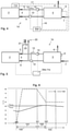
- FIG. 1 to 5 Various embodiments of water heating systems 1a, 1b, 1c, 1d, 1e according to the invention are shown, which each have control devices 50a, 50b, 50c, 50d, 50e according to the invention.
- the control devices 50a, 50b, 50c, 50d, 50e each have a computing unit (not shown) which is set up to carry out methods according to the invention for preparing hot water in a building.
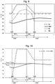
- Various embodiments of the method according to the invention based on progression graphics according to Figures 8 to 10 are explained.
- the history graphs according to 6 and 7 show processes for water heating according to the company's own state-of-the-art technology.
- the water heating system 1a shown comprises a heat source 2, a heat accumulator 3 and a charging circuit 4 for transferring heat from the heat source 2 to the heat accumulator 3.
- the charging circuit 4 is a closed circuit between the heat source 2 and the heat accumulator 3, in which a heat carrier, e.g .Water, circulating.
- the heat transfer medium is heated in the heat source 2 and is fed from the heat source 2 to the heat accumulator 3 via a feed line 5 of the charging circuit 4 and returned to the heat source 2 in a return line 6 of the charging circuit 4 after the heat has been released in the heat accumulator 3.
- a heat exchanger (not shown) is provided in the heat accumulator 3, via which the water in the heat accumulator 3 is heated.
- Cold water is supplied to the heat accumulator via a cold water inlet 7 and heated to a desired temperature in the heat accumulator 3 and stored for a longer period of time.
- the heat accumulator 3 is particularly preferably not an instantaneous water heater, but is used for heating and longer storage of hot water, which can be tapped from the heat accumulator at any time. Consumers can then call up the hot water from the heat accumulator 3 via a distribution line 8 when required, for example by tapping a faucet.
- the hot water temperature can be measured by a hot water temperature sensor 9 .
- the circulation of the heat transfer medium in the charging circuit 4 is achieved by a circulating pump 10 that can be switched on and off.
- the water heating system according to the invention 1a is controlled by a belonging to the water heating system 1a control device 50a.
- the control device comprises an in 1 not shown separately controller 11a, which coincides with the control device 50a in this embodiment.
- the functions of the controller 11a include the basic control of the hot water preparation system 1a with the Switching the heat source 2 on and off, regulating the flow temperature in the charging circuit 4 and switching the circulation pump 10 on and off, depending on the hot water temperature measured in the heat accumulator 3 by the hot water temperature sensor 9 . If this falls to a value that is too low in the hot water temperature storage tank, the hot water preparation is activated as part of the basic control until the hot water in the heat storage tank (as already described) has been sufficiently heated.
- control device 50a is provided with an interface, not shown in detail, which has a first control connection for connection to the heat source 2 and a second control connection for connection to the circulation pump 10 in the charging circuit 4 as well as a second sensor connection for the hot water sensor 9. All connections in this exemplary embodiment are shown as dashed lines, which can symbolize both a wired connection and a wireless connection.
- the arithmetic unit (not shown) of the control device 50a is set up to carry out the method according to the invention, which has already been described in detail at the outset and will be briefly described again later with the aid of graphs.
- the interface of the control device has a first sensor connection, which is connected to a heat meter 12 and a flow temperature sensor 13 in order to obtain further measured values required for carrying out the method according to the invention.
- Other embodiments provide a flow temperature sensor 13 and a return temperature sensor 14 instead of the combination of heat meter 12 and flow temperature sensor 13 described here. This combination can be arbitrarily exchanged between the embodiments.
- control device 50b of the embodiment described above in principle similar.
- the main difference is that the controller 11b for basic control is assigned directly to the heat source 2 and is directly connected to the circulation pump 10 and the hot water temperature sensor 9.
- the control device 50b set up for carrying out the method according to the invention is connected to the controller via a communication connection 15 and via this indirectly to the circulation pump 10 and the hot water temperature sensor 9 .
- the control device 50b is therefore provided separately from the controller 11b.
- the water heating system 1c in 3 corresponds to the water heating system 1b 2 with the difference that instead of the heat meter 12 in the return 6 of the charging circuit 4, a return temperature sensor 14 is provided on the return 6, analogous to the flow temperature sensor 13 on the flow 5 of the charging circuit 4.
- the embodiment of the water heating system 1d in 4 differs from the water heating system 1c ( 3 ) in that the control device 50d cannot be switched to the controller 11d, ie there is no communication connection between the control device 50d and the controller 11d. Instead, it is provided that the control device 50d has a control input which is connected to a control output of the controller 11d for connection 16 to the circulation pump 10, and has a measured value output which is set up at a measured value input of the controller for connection 17 to the hot water temperature sensor 9. The control device 50d is then connected directly to the circulation pump 10 and the hot water temperature sensor 9.
- the circulation pump 10 and the hot water temperature sensor are separated from the controller 11d and connected directly to the control device 50d.
- the regulator 11d receives the resistance value for the as a simulation value Temperature measurement instead of the hot water temperature sensor 9 by the control device 50d, which can thereby achieve a premature shutdown of the heat source 2, by appropriate simulation of a suitable resistance value.
- the circulation pump 10 is also controlled directly by the control device 50d, so that the run-on phase can be lengthened or shortened as required.
- water heating system 1e corresponds to the water heating system 1a according to 1 with the difference that the water heating system 1e is part of a heating system.
- a heating circuit is connected to the charging circuit 4, via which the heat transfer medium is fed to building heating surfaces (not shown).
- a feed 21 of the heating circuit 20 is connected to the feed 5 of the charging circuit 4 and a return 22 of the heating circuit 20 to a return 6 of the charging circuit 4, with the feed 21 and the return 22 of the heating circuit 20 being connected via a mixing valve 23 in order to flow temperature T HK in heating circuit 20.
- a heating circuit flow temperature sensor 24 is provided in the flow 21 of the heating circuit 20.
- typical temperature curves T over time t are shown in conventional hot water preparation, namely the flow temperature in the charging circuit 4 and the hot water temperature T WW in the heat accumulator 3, as measured by the hot water temperature sensor 9.
- the content of the heat accumulator 3 continues to heat up after the end of the charging phase 101 (the heat source 2 is switched off).
- the run-on phase 120 is too short for the heat contained in the heat source 2 and charging circuit 4 to be completely released to the heat accumulator content.
- the cooling phase 103 begins, in which part of the heat stored in the heat transfer medium (flow temperature and return temperature T RL that are significantly higher than the hot water temperature T WW ) cools down without being used. An unnecessary energy input is consumed for this purpose.
- the run-on phase 102 can be shorter or longer compared to the fixed time of a conventional controller.
- a maximum duration can also be defined in order to avoid undesirably long runtimes.
- the corresponding temperature profile results from 10 .
Landscapes
- Engineering & Computer Science (AREA)
- Physics & Mathematics (AREA)
- Thermal Sciences (AREA)
- Chemical & Material Sciences (AREA)
- Combustion & Propulsion (AREA)
- Mechanical Engineering (AREA)
- General Engineering & Computer Science (AREA)
- Water Supply & Treatment (AREA)
- Heat-Pump Type And Storage Water Heaters (AREA)
- Steam Or Hot-Water Central Heating Systems (AREA)
Applications Claiming Priority (1)
| Application Number | Priority Date | Filing Date | Title |
|---|---|---|---|
| DE102020124153.4A DE102020124153A1 (de) | 2020-09-16 | 2020-09-16 | Verfahren zur Bereitung von Warmwasser in einem Gebäude, Warmwasserbereitungsanlage und Steuereinrichtung für eine Warmwasserbereitungsanlage |
Publications (2)
| Publication Number | Publication Date |
|---|---|
| EP3971484A1 true EP3971484A1 (fr) | 2022-03-23 |
| EP3971484B1 EP3971484B1 (fr) | 2024-09-18 |
Family
ID=76601106
Family Applications (1)
| Application Number | Title | Priority Date | Filing Date |
|---|---|---|---|
| EP21181483.5A Active EP3971484B1 (fr) | 2020-09-16 | 2021-06-24 | Procédé de production d'eau chaude dans un bâtiment, installation de production d'eau chaude et dispositif de commande d'une installation de production d'eau chaude |
Country Status (3)
| Country | Link |
|---|---|
| EP (1) | EP3971484B1 (fr) |
| DE (1) | DE102020124153A1 (fr) |
| PL (1) | PL3971484T3 (fr) |
Citations (4)
| Publication number | Priority date | Publication date | Assignee | Title |
|---|---|---|---|---|
| DE3529814A1 (de) * | 1985-07-02 | 1987-01-08 | Landis & Gyr Ag | Regelgeraet fuer eine heizungsanlage mit boiler-vorrangschaltung |
| DE4444987C1 (de) * | 1994-12-16 | 1996-04-18 | Buderus Heiztechnik Gmbh | Verfahren zur Regelung der Brauchwasseraufheizung in einer Heizungsanlage |
| EP0711960A1 (fr) * | 1994-11-14 | 1996-05-15 | Landis & Gyr Technology Innovation AG | Procédé et dispositif pour chauffer de l'eau sanitaire |
| EP1403588A2 (fr) * | 2002-09-24 | 2004-03-31 | Robert Bosch Gmbh | Installation de chauffage pour bâtiment |
Family Cites Families (2)
| Publication number | Priority date | Publication date | Assignee | Title |
|---|---|---|---|---|
| DE10203394B4 (de) | 2001-01-31 | 2016-11-24 | Vaillant Gmbh | Verfahren zum Betrieb eines Warmwasserspeichers |
| DE102010033620A1 (de) | 2010-08-06 | 2012-02-09 | Robert Bosch Gmbh | Verfahren und Vorrichtung zum Erwärmen eines Fluids in einem Pufferspeicher |
-
2020
- 2020-09-16 DE DE102020124153.4A patent/DE102020124153A1/de not_active Withdrawn
-
2021
- 2021-06-24 PL PL21181483.5T patent/PL3971484T3/pl unknown
- 2021-06-24 EP EP21181483.5A patent/EP3971484B1/fr active Active
Patent Citations (4)
| Publication number | Priority date | Publication date | Assignee | Title |
|---|---|---|---|---|
| DE3529814A1 (de) * | 1985-07-02 | 1987-01-08 | Landis & Gyr Ag | Regelgeraet fuer eine heizungsanlage mit boiler-vorrangschaltung |
| EP0711960A1 (fr) * | 1994-11-14 | 1996-05-15 | Landis & Gyr Technology Innovation AG | Procédé et dispositif pour chauffer de l'eau sanitaire |
| DE4444987C1 (de) * | 1994-12-16 | 1996-04-18 | Buderus Heiztechnik Gmbh | Verfahren zur Regelung der Brauchwasseraufheizung in einer Heizungsanlage |
| EP1403588A2 (fr) * | 2002-09-24 | 2004-03-31 | Robert Bosch Gmbh | Installation de chauffage pour bâtiment |
Also Published As
| Publication number | Publication date |
|---|---|
| PL3971484T3 (pl) | 2025-04-14 |
| EP3971484B1 (fr) | 2024-09-18 |
| DE102020124153A1 (de) | 2022-03-17 |
Similar Documents
| Publication | Publication Date | Title |
|---|---|---|
| DE102019000430B4 (de) | Verfahren zur Erreichung sehr niedriger Rücklauftemperaturen mittels einer Wärmepumpe, Heizanordnung zur Durchführung des Verfahrens, sowie System für Wärme- und Kälteverteilnetze | |
| DE102014103668A1 (de) | Verfahren zum Betrieb einer Heiz- und/oder Kühlanlage | |
| EP2187136A2 (fr) | Procédé de fonctionnement d'un système de transport d'énergie thermique sur un support fluide | |
| EP2416073A2 (fr) | Procédé et dispositif destinés au chauffage d'un fluide dans une mémoire tampon | |
| WO2019081501A1 (fr) | Système de gestion d'énergie permettant une détermination et une régulation anticipées d'une température de départ d'un dispositif de chauffage d'un bâtiment | |
| EP3059652A1 (fr) | Dispositif de commande et installation de regulation de temperature ambiante | |
| EP0807790B1 (fr) | Méthode et système pour préparer de l'eau chaude sanitaire | |
| DE102020102532B4 (de) | Anpassungsschaltung zur Regelung einer Leistungsabgabe an eine resistive Last und Schaltungsvorrichtung zur Versorgung eines Warmwassererzeugers aus einer regenerativen Energiequelle | |
| DE2606535A1 (de) | Temperatursystem | |
| EP0038318A1 (fr) | Dispositif de réglage pour le réglage du chauffage d'eau sanitaire pour un ballon de stockage | |
| EP3800403B1 (fr) | Procédé de fonctionnement d'un dispositif de chauffage, dispositif de chauffage | |
| EP3971484B1 (fr) | Procédé de production d'eau chaude dans un bâtiment, installation de production d'eau chaude et dispositif de commande d'une installation de production d'eau chaude | |
| EP3385624B1 (fr) | Procédé de fonctionnement d'une installation de préparation d'eau sanitaire ou de chauffage, et installation de préparation d'eau sanitaire | |
| AT517246B1 (de) | Heizungs- oder kühlungsanlage und verfahren zum betrieb einer heizungs- oder kühlungsanlage | |
| EP3139103B1 (fr) | Procédé de préparation de boissons chaudes | |
| DE3030565A1 (de) | Heizkessel fuer heizungsanlagen | |
| DE102010056301B4 (de) | Verfahren zur automatischen Optimierung einer Aufheizphase eines Heizsystems sowie ein Heizsystem | |
| EP4015918B1 (fr) | Procédé et dispositif de commande d'un circuit primaire d'une installation de chauffage | |
| DE19824543C1 (de) | Verfahren und Vorrichtung zur Regelung von Umwälzpumpen in den Solarkollektorkreisen von Solaranlagen mit Speicher | |
| DE102018115838A1 (de) | Verfahren zum Betrieb einer Temperieranlage, Temperieranlage sowie Messvorrichtung | |
| EP3835667B1 (fr) | Procédé de commande d'une installation de chauffage et appareil de commande associé | |
| DE102009008649B4 (de) | Verfahren und Vorrichtung zum Regeln der Laufzeit eines Brenners | |
| EP2199690B1 (fr) | Procédé et dispositif destinés au réglage d'une installation solaire thermique | |
| EP0711960A1 (fr) | Procédé et dispositif pour chauffer de l'eau sanitaire | |
| EP0352401A1 (fr) | Procédure pour régler la quantité de chaleur apportée aux utilisateurs dans un système de chauffage et équipement de réglage. |
Legal Events
| Date | Code | Title | Description |
|---|---|---|---|
| PUAI | Public reference made under article 153(3) epc to a published international application that has entered the european phase |
Free format text: ORIGINAL CODE: 0009012 |
|
| STAA | Information on the status of an ep patent application or granted ep patent |
Free format text: STATUS: THE APPLICATION HAS BEEN PUBLISHED |
|
| AK | Designated contracting states |
Kind code of ref document: A1 Designated state(s): AL AT BE BG CH CY CZ DE DK EE ES FI FR GB GR HR HU IE IS IT LI LT LU LV MC MK MT NL NO PL PT RO RS SE SI SK SM TR |
|
| STAA | Information on the status of an ep patent application or granted ep patent |
Free format text: STATUS: REQUEST FOR EXAMINATION WAS MADE |
|
| 17P | Request for examination filed |
Effective date: 20220920 |
|
| RBV | Designated contracting states (corrected) |
Designated state(s): AL AT BE BG CH CY CZ DE DK EE ES FI FR GB GR HR HU IE IS IT LI LT LU LV MC MK MT NL NO PL PT RO RS SE SI SK SM TR |
|
| RIC1 | Information provided on ipc code assigned before grant |
Ipc: F24D 19/10 20060101ALI20240301BHEP Ipc: F24D 17/00 20220101ALI20240301BHEP Ipc: F24D 3/08 20060101AFI20240301BHEP |
|
| GRAP | Despatch of communication of intention to grant a patent |
Free format text: ORIGINAL CODE: EPIDOSNIGR1 |
|
| STAA | Information on the status of an ep patent application or granted ep patent |
Free format text: STATUS: GRANT OF PATENT IS INTENDED |
|
| INTG | Intention to grant announced |
Effective date: 20240415 |
|
| GRAS | Grant fee paid |
Free format text: ORIGINAL CODE: EPIDOSNIGR3 |
|
| GRAA | (expected) grant |
Free format text: ORIGINAL CODE: 0009210 |
|
| STAA | Information on the status of an ep patent application or granted ep patent |
Free format text: STATUS: THE PATENT HAS BEEN GRANTED |
|
| AK | Designated contracting states |
Kind code of ref document: B1 Designated state(s): AL AT BE BG CH CY CZ DE DK EE ES FI FR GB GR HR HU IE IS IT LI LT LU LV MC MK MT NL NO PL PT RO RS SE SI SK SM TR |
|
| REG | Reference to a national code |
Ref country code: GB Ref legal event code: FG4D Free format text: NOT ENGLISH |
|
| REG | Reference to a national code |
Ref country code: CH Ref legal event code: EP |
|
| REG | Reference to a national code |
Ref country code: DE Ref legal event code: R096 Ref document number: 502021005165 Country of ref document: DE |
|
| REG | Reference to a national code |
Ref country code: IE Ref legal event code: FG4D Free format text: LANGUAGE OF EP DOCUMENT: GERMAN |
|
| P01 | Opt-out of the competence of the unified patent court (upc) registered |
Free format text: CASE NUMBER: APP_56444/2024 Effective date: 20241016 |
|
| REG | Reference to a national code |
Ref country code: LT Ref legal event code: MG9D |
|
| PG25 | Lapsed in a contracting state [announced via postgrant information from national office to epo] |
Ref country code: NO Free format text: LAPSE BECAUSE OF FAILURE TO SUBMIT A TRANSLATION OF THE DESCRIPTION OR TO PAY THE FEE WITHIN THE PRESCRIBED TIME-LIMIT Effective date: 20241218 |
|
| PG25 | Lapsed in a contracting state [announced via postgrant information from national office to epo] |
Ref country code: GR Free format text: LAPSE BECAUSE OF FAILURE TO SUBMIT A TRANSLATION OF THE DESCRIPTION OR TO PAY THE FEE WITHIN THE PRESCRIBED TIME-LIMIT Effective date: 20241219 Ref country code: FI Free format text: LAPSE BECAUSE OF FAILURE TO SUBMIT A TRANSLATION OF THE DESCRIPTION OR TO PAY THE FEE WITHIN THE PRESCRIBED TIME-LIMIT Effective date: 20240918 |
|
| PG25 | Lapsed in a contracting state [announced via postgrant information from national office to epo] |
Ref country code: BG Free format text: LAPSE BECAUSE OF FAILURE TO SUBMIT A TRANSLATION OF THE DESCRIPTION OR TO PAY THE FEE WITHIN THE PRESCRIBED TIME-LIMIT Effective date: 20240918 |
|
| PG25 | Lapsed in a contracting state [announced via postgrant information from national office to epo] |
Ref country code: LV Free format text: LAPSE BECAUSE OF FAILURE TO SUBMIT A TRANSLATION OF THE DESCRIPTION OR TO PAY THE FEE WITHIN THE PRESCRIBED TIME-LIMIT Effective date: 20240918 |
|
| PG25 | Lapsed in a contracting state [announced via postgrant information from national office to epo] |
Ref country code: HR Free format text: LAPSE BECAUSE OF FAILURE TO SUBMIT A TRANSLATION OF THE DESCRIPTION OR TO PAY THE FEE WITHIN THE PRESCRIBED TIME-LIMIT Effective date: 20240918 |
|
| REG | Reference to a national code |
Ref country code: NL Ref legal event code: MP Effective date: 20240918 |
|
| PG25 | Lapsed in a contracting state [announced via postgrant information from national office to epo] |
Ref country code: RS Free format text: LAPSE BECAUSE OF FAILURE TO SUBMIT A TRANSLATION OF THE DESCRIPTION OR TO PAY THE FEE WITHIN THE PRESCRIBED TIME-LIMIT Effective date: 20241218 |
|
| PG25 | Lapsed in a contracting state [announced via postgrant information from national office to epo] |
Ref country code: RS Free format text: LAPSE BECAUSE OF FAILURE TO SUBMIT A TRANSLATION OF THE DESCRIPTION OR TO PAY THE FEE WITHIN THE PRESCRIBED TIME-LIMIT Effective date: 20241218 Ref country code: NO Free format text: LAPSE BECAUSE OF FAILURE TO SUBMIT A TRANSLATION OF THE DESCRIPTION OR TO PAY THE FEE WITHIN THE PRESCRIBED TIME-LIMIT Effective date: 20241218 Ref country code: LV Free format text: LAPSE BECAUSE OF FAILURE TO SUBMIT A TRANSLATION OF THE DESCRIPTION OR TO PAY THE FEE WITHIN THE PRESCRIBED TIME-LIMIT Effective date: 20240918 Ref country code: HR Free format text: LAPSE BECAUSE OF FAILURE TO SUBMIT A TRANSLATION OF THE DESCRIPTION OR TO PAY THE FEE WITHIN THE PRESCRIBED TIME-LIMIT Effective date: 20240918 Ref country code: GR Free format text: LAPSE BECAUSE OF FAILURE TO SUBMIT A TRANSLATION OF THE DESCRIPTION OR TO PAY THE FEE WITHIN THE PRESCRIBED TIME-LIMIT Effective date: 20241219 Ref country code: FI Free format text: LAPSE BECAUSE OF FAILURE TO SUBMIT A TRANSLATION OF THE DESCRIPTION OR TO PAY THE FEE WITHIN THE PRESCRIBED TIME-LIMIT Effective date: 20240918 Ref country code: BG Free format text: LAPSE BECAUSE OF FAILURE TO SUBMIT A TRANSLATION OF THE DESCRIPTION OR TO PAY THE FEE WITHIN THE PRESCRIBED TIME-LIMIT Effective date: 20240918 |
|
| PG25 | Lapsed in a contracting state [announced via postgrant information from national office to epo] |
Ref country code: NL Free format text: LAPSE BECAUSE OF FAILURE TO SUBMIT A TRANSLATION OF THE DESCRIPTION OR TO PAY THE FEE WITHIN THE PRESCRIBED TIME-LIMIT Effective date: 20240918 |
|
| PG25 | Lapsed in a contracting state [announced via postgrant information from national office to epo] |
Ref country code: PT Free format text: LAPSE BECAUSE OF FAILURE TO SUBMIT A TRANSLATION OF THE DESCRIPTION OR TO PAY THE FEE WITHIN THE PRESCRIBED TIME-LIMIT Effective date: 20250120 Ref country code: IS Free format text: LAPSE BECAUSE OF FAILURE TO SUBMIT A TRANSLATION OF THE DESCRIPTION OR TO PAY THE FEE WITHIN THE PRESCRIBED TIME-LIMIT Effective date: 20250118 |
|
| PG25 | Lapsed in a contracting state [announced via postgrant information from national office to epo] |
Ref country code: SM Free format text: LAPSE BECAUSE OF FAILURE TO SUBMIT A TRANSLATION OF THE DESCRIPTION OR TO PAY THE FEE WITHIN THE PRESCRIBED TIME-LIMIT Effective date: 20240918 Ref country code: RO Free format text: LAPSE BECAUSE OF FAILURE TO SUBMIT A TRANSLATION OF THE DESCRIPTION OR TO PAY THE FEE WITHIN THE PRESCRIBED TIME-LIMIT Effective date: 20240918 |
|
| PG25 | Lapsed in a contracting state [announced via postgrant information from national office to epo] |
Ref country code: ES Free format text: LAPSE BECAUSE OF FAILURE TO SUBMIT A TRANSLATION OF THE DESCRIPTION OR TO PAY THE FEE WITHIN THE PRESCRIBED TIME-LIMIT Effective date: 20240918 |
|
| PG25 | Lapsed in a contracting state [announced via postgrant information from national office to epo] |
Ref country code: EE Free format text: LAPSE BECAUSE OF FAILURE TO SUBMIT A TRANSLATION OF THE DESCRIPTION OR TO PAY THE FEE WITHIN THE PRESCRIBED TIME-LIMIT Effective date: 20240918 |
|
| PG25 | Lapsed in a contracting state [announced via postgrant information from national office to epo] |
Ref country code: CZ Free format text: LAPSE BECAUSE OF FAILURE TO SUBMIT A TRANSLATION OF THE DESCRIPTION OR TO PAY THE FEE WITHIN THE PRESCRIBED TIME-LIMIT Effective date: 20240918 |
|
| PG25 | Lapsed in a contracting state [announced via postgrant information from national office to epo] |
Ref country code: SK Free format text: LAPSE BECAUSE OF FAILURE TO SUBMIT A TRANSLATION OF THE DESCRIPTION OR TO PAY THE FEE WITHIN THE PRESCRIBED TIME-LIMIT Effective date: 20240918 Ref country code: IT Free format text: LAPSE BECAUSE OF FAILURE TO SUBMIT A TRANSLATION OF THE DESCRIPTION OR TO PAY THE FEE WITHIN THE PRESCRIBED TIME-LIMIT Effective date: 20240918 |
|
| REG | Reference to a national code |
Ref country code: DE Ref legal event code: R097 Ref document number: 502021005165 Country of ref document: DE |
|
| PG25 | Lapsed in a contracting state [announced via postgrant information from national office to epo] |
Ref country code: DK Free format text: LAPSE BECAUSE OF FAILURE TO SUBMIT A TRANSLATION OF THE DESCRIPTION OR TO PAY THE FEE WITHIN THE PRESCRIBED TIME-LIMIT Effective date: 20240918 |
|
| PGFP | Annual fee paid to national office [announced via postgrant information from national office to epo] |
Ref country code: AT Payment date: 20250721 Year of fee payment: 5 |
|
| PLBE | No opposition filed within time limit |
Free format text: ORIGINAL CODE: 0009261 |
|
| STAA | Information on the status of an ep patent application or granted ep patent |
Free format text: STATUS: NO OPPOSITION FILED WITHIN TIME LIMIT |
|
| 26N | No opposition filed |
Effective date: 20250619 |
|
| PG25 | Lapsed in a contracting state [announced via postgrant information from national office to epo] |
Ref country code: SE Free format text: LAPSE BECAUSE OF FAILURE TO SUBMIT A TRANSLATION OF THE DESCRIPTION OR TO PAY THE FEE WITHIN THE PRESCRIBED TIME-LIMIT Effective date: 20240918 |
|
| PGFP | Annual fee paid to national office [announced via postgrant information from national office to epo] |
Ref country code: DE Payment date: 20250722 Year of fee payment: 5 |
|
| PGFP | Annual fee paid to national office [announced via postgrant information from national office to epo] |
Ref country code: PL Payment date: 20250722 Year of fee payment: 5 |
|
| PGFP | Annual fee paid to national office [announced via postgrant information from national office to epo] |
Ref country code: CH Payment date: 20250722 Year of fee payment: 5 |
|
| PG25 | Lapsed in a contracting state [announced via postgrant information from national office to epo] |
Ref country code: MC Free format text: LAPSE BECAUSE OF FAILURE TO SUBMIT A TRANSLATION OF THE DESCRIPTION OR TO PAY THE FEE WITHIN THE PRESCRIBED TIME-LIMIT Effective date: 20240918 |
|
| PG25 | Lapsed in a contracting state [announced via postgrant information from national office to epo] |
Ref country code: LU Free format text: LAPSE BECAUSE OF NON-PAYMENT OF DUE FEES Effective date: 20250624 |
|
| GBPC | Gb: european patent ceased through non-payment of renewal fee |
Effective date: 20250624 |
|
| REG | Reference to a national code |
Ref country code: BE Ref legal event code: MM Effective date: 20250630 |
|
| PG25 | Lapsed in a contracting state [announced via postgrant information from national office to epo] |
Ref country code: GB Free format text: LAPSE BECAUSE OF NON-PAYMENT OF DUE FEES Effective date: 20250624 |
|
| PG25 | Lapsed in a contracting state [announced via postgrant information from national office to epo] |
Ref country code: IE Free format text: LAPSE BECAUSE OF NON-PAYMENT OF DUE FEES Effective date: 20250624 |
|
| PG25 | Lapsed in a contracting state [announced via postgrant information from national office to epo] |
Ref country code: BE Free format text: LAPSE BECAUSE OF NON-PAYMENT OF DUE FEES Effective date: 20250630 |
|
| PG25 | Lapsed in a contracting state [announced via postgrant information from national office to epo] |
Ref country code: FR Free format text: LAPSE BECAUSE OF NON-PAYMENT OF DUE FEES Effective date: 20250630 |