EP3974073A1 - Laminage en fonction de la réponse de fréquence - Google Patents
Laminage en fonction de la réponse de fréquence Download PDFInfo
- Publication number
- EP3974073A1 EP3974073A1 EP20198745.0A EP20198745A EP3974073A1 EP 3974073 A1 EP3974073 A1 EP 3974073A1 EP 20198745 A EP20198745 A EP 20198745A EP 3974073 A1 EP3974073 A1 EP 3974073A1
- Authority
- EP
- European Patent Office
- Prior art keywords
- metal strip
- thickness
- roll stand
- control device
- section
- Prior art date
- Legal status (The legal status is an assumption and is not a legal conclusion. Google has not performed a legal analysis and makes no representation as to the accuracy of the status listed.)
- Granted
Links
Images



Classifications
-
- B—PERFORMING OPERATIONS; TRANSPORTING
- B21—MECHANICAL METAL-WORKING WITHOUT ESSENTIALLY REMOVING MATERIAL; PUNCHING METAL
- B21B—ROLLING OF METAL
- B21B37/00—Control devices or methods specially adapted for metal-rolling mills or the work produced thereby
- B21B37/58—Roll-force control; Roll-gap control
-
- B—PERFORMING OPERATIONS; TRANSPORTING
- B21—MECHANICAL METAL-WORKING WITHOUT ESSENTIALLY REMOVING MATERIAL; PUNCHING METAL
- B21B—ROLLING OF METAL
- B21B37/00—Control devices or methods specially adapted for metal-rolling mills or the work produced thereby
- B21B37/16—Control of thickness, width, diameter or other transverse dimensions
- B21B37/165—Control of thickness, width, diameter or other transverse dimensions responsive mainly to the measured thickness of the product
-
- G—PHYSICS
- G05—CONTROLLING; REGULATING
- G05B—CONTROL OR REGULATING SYSTEMS IN GENERAL; FUNCTIONAL ELEMENTS OF SUCH SYSTEMS; MONITORING OR TESTING ARRANGEMENTS FOR SUCH SYSTEMS OR ELEMENTS
- G05B19/00—Program-control systems
-
- B—PERFORMING OPERATIONS; TRANSPORTING
- B21—MECHANICAL METAL-WORKING WITHOUT ESSENTIALLY REMOVING MATERIAL; PUNCHING METAL
- B21B—ROLLING OF METAL
- B21B15/00—Arrangements for performing additional metal-working operations specially combined with or arranged in, or specially adapted for use in connection with, metal-rolling mills
- B21B2015/0057—Coiling the rolled product
-
- B—PERFORMING OPERATIONS; TRANSPORTING
- B21—MECHANICAL METAL-WORKING WITHOUT ESSENTIALLY REMOVING MATERIAL; PUNCHING METAL
- B21B—ROLLING OF METAL
- B21B15/00—Arrangements for performing additional metal-working operations specially combined with or arranged in, or specially adapted for use in connection with, metal-rolling mills
- B21B2015/0064—Uncoiling the rolled product
-
- B—PERFORMING OPERATIONS; TRANSPORTING
- B21—MECHANICAL METAL-WORKING WITHOUT ESSENTIALLY REMOVING MATERIAL; PUNCHING METAL
- B21B—ROLLING OF METAL
- B21B2261/00—Product parameters
- B21B2261/02—Transverse dimensions
- B21B2261/04—Thickness, gauge
-
- B—PERFORMING OPERATIONS; TRANSPORTING
- B21—MECHANICAL METAL-WORKING WITHOUT ESSENTIALLY REMOVING MATERIAL; PUNCHING METAL
- B21B—ROLLING OF METAL
- B21B2271/00—Mill stand parameters
- B21B2271/02—Roll gap, screw-down position, draft position
-
- B—PERFORMING OPERATIONS; TRANSPORTING
- B21—MECHANICAL METAL-WORKING WITHOUT ESSENTIALLY REMOVING MATERIAL; PUNCHING METAL
- B21B—ROLLING OF METAL
- B21B2273/00—Path parameters
- B21B2273/20—Track of product
-
- B—PERFORMING OPERATIONS; TRANSPORTING
- B21—MECHANICAL METAL-WORKING WITHOUT ESSENTIALLY REMOVING MATERIAL; PUNCHING METAL
- B21B—ROLLING OF METAL
- B21B2275/00—Mill drive parameters
- B21B2275/02—Speed
- B21B2275/04—Roll speed
-
- B—PERFORMING OPERATIONS; TRANSPORTING
- B21—MECHANICAL METAL-WORKING WITHOUT ESSENTIALLY REMOVING MATERIAL; PUNCHING METAL
- B21B—ROLLING OF METAL
- B21B2275/00—Mill drive parameters
- B21B2275/10—Motor power; motor current
-
- B—PERFORMING OPERATIONS; TRANSPORTING
- B21—MECHANICAL METAL-WORKING WITHOUT ESSENTIALLY REMOVING MATERIAL; PUNCHING METAL
- B21B—ROLLING OF METAL
- B21B2275/00—Mill drive parameters
- B21B2275/10—Motor power; motor current
- B21B2275/12—Roll torque
-
- B—PERFORMING OPERATIONS; TRANSPORTING
- B21—MECHANICAL METAL-WORKING WITHOUT ESSENTIALLY REMOVING MATERIAL; PUNCHING METAL
- B21B—ROLLING OF METAL
- B21B37/00—Control devices or methods specially adapted for metal-rolling mills or the work produced thereby
- B21B37/46—Roll speed or drive motor control
-
- B—PERFORMING OPERATIONS; TRANSPORTING
- B21—MECHANICAL METAL-WORKING WITHOUT ESSENTIALLY REMOVING MATERIAL; PUNCHING METAL
- B21B—ROLLING OF METAL
- B21B37/00—Control devices or methods specially adapted for metal-rolling mills or the work produced thereby
- B21B37/48—Tension control; Compression control
- B21B37/52—Tension control; Compression control by drive motor control
- B21B37/54—Tension control; Compression control by drive motor control including coiler drive control, e.g. reversing mills
-
- B—PERFORMING OPERATIONS; TRANSPORTING
- B21—MECHANICAL METAL-WORKING WITHOUT ESSENTIALLY REMOVING MATERIAL; PUNCHING METAL
- B21B—ROLLING OF METAL
- B21B37/00—Control devices or methods specially adapted for metal-rolling mills or the work produced thereby
- B21B37/58—Roll-force control; Roll-gap control
- B21B37/62—Roll-force control; Roll-gap control by control of a hydraulic adjusting device
-
- G—PHYSICS
- G05—CONTROLLING; REGULATING
- G05B—CONTROL OR REGULATING SYSTEMS IN GENERAL; FUNCTIONAL ELEMENTS OF SUCH SYSTEMS; MONITORING OR TESTING ARRANGEMENTS FOR SUCH SYSTEMS OR ELEMENTS
- G05B2219/00—Program-control systems
-
- G—PHYSICS
- G05—CONTROLLING; REGULATING
- G05B—CONTROL OR REGULATING SYSTEMS IN GENERAL; FUNCTIONAL ELEMENTS OF SUCH SYSTEMS; MONITORING OR TESTING ARRANGEMENTS FOR SUCH SYSTEMS OR ELEMENTS
- G05B2219/00—Program-control systems
- G05B2219/20—Pc systems
- G05B2219/21—Pc I-O input output
- G05B2219/21129—Low pass filter for input
-
- G—PHYSICS
- G05—CONTROLLING; REGULATING
- G05B—CONTROL OR REGULATING SYSTEMS IN GENERAL; FUNCTIONAL ELEMENTS OF SUCH SYSTEMS; MONITORING OR TESTING ARRANGEMENTS FOR SUCH SYSTEMS OR ELEMENTS
- G05B2219/00—Program-control systems
- G05B2219/30—Nc systems
- G05B2219/37—Measurements
- G05B2219/37527—Frequency filtering and amplitude qualification
-
- G—PHYSICS
- G05—CONTROLLING; REGULATING
- G05B—CONTROL OR REGULATING SYSTEMS IN GENERAL; FUNCTIONAL ELEMENTS OF SUCH SYSTEMS; MONITORING OR TESTING ARRANGEMENTS FOR SUCH SYSTEMS OR ELEMENTS
- G05B2219/00—Program-control systems
- G05B2219/30—Nc systems
- G05B2219/41—Servomotor, servo controller till figures
- G05B2219/41149—Zero phase filter
Definitions
- the present invention is also based on a control program that includes machine code that can be processed by a control device for a rolling mill, the processing of the machine code by the control device causes the controller to operate the rolling mill according to such an operating method.
- the present invention is also based on a control device for a rolling mill, the control device being programmed with such a control program so that the control device operates the rolling mill according to such an operating method.
- the slab is first hot-rolled, resulting in a hot strip.
- the thickness of the hot strip is usually in the range of a few millimeters, depending on the manufacturing process sometimes a little more or less, for example between 1.0 mm and 20 mm in a normal hot rolling mill and between 0.6 mm and 6 mm in a so-called ESP plant .
- the hot strip is further processed without further reduction in thickness.
- the strip thickness is further reduced after hot rolling in a cold rolling mill.
- the aim of cold rolling is to produce a cold-rolled metal strip whose final thickness matches a target thickness as closely as possible and with as little deviation as possible.
- the finished hot strip - ie after hot rolling but before rolling in the cold rolling mill - shows deviations in thickness.
- the thickness deviations often have both periodic components and stochastic components. If these deviations are not compensated for, the metal strip will also exhibit such deviations after cold rolling. Although the absolute extent of the deviations is smaller than with hot strip, the relative deviation remains the same. If - for example - the metal strip before cold rolling has a thickness of 3.0 mm and thickness deviations in the range of 30 ⁇ m and the metal strip has a thickness of 1.0 mm after cold rolling, the metal strip shows without compensation for the thickness deviations thickness deviations in the range of 10 ⁇ m during cold rolling.
- EP 0 435 595 A2 The procedure of EP 0 435 595 A2 is based on the idea that the regulation by the feeding device itself and the receiving device itself is very sluggish and the dynamics of the regulation can be increased by the additional rollers.
- a procedure is also described in which the thickness and the speed of the metal strip are controlled on the entry side of the roll stand recorded and used within the scope of determining the adjustment of the roll stand.
- EP 3 332 883 A1 is also known to detect the thickness of the rolled metal strip on the outlet side of a roll stand and to regulate the thickness of the roll stand. Periodic deviations are separated from stochastic deviations. Periodic deviations are considered to be caused by eccentricities of the mill rolls. The adjustment of the roll stand is corrected accordingly.
- the thickness of the still unrolled metal strip is recorded on the entry side of the roll stand and averaged over certain length units.
- the mean value is used to control the adjustment of the roll stand.
- the object of the present invention is to create possibilities by means of which an excellent compensation of thickness deviations of the metal strip on the outlet side can be achieved.
- an operating method of the type mentioned is designed in that the control device determines at least one of the target values based on the number of final thickness deviations, taking into account a description of the inverse frequency behavior of the respective actuator.
- the number of final thickness deviations is equal to 1.
- the control device calculates the - in this case only - final thickness deviation of the respective cycle based on a final inlet-side thickness of the section of the metal strip, taking into account an infeed speed which the section of the metal strip enters the roll stand, and an exit speed with which the section of the metal strip runs out of the roll stand, determined using the mass flow equation.
- the section of the metal strip to which the determined final thickness deviation relates is the currently rolled section of the metal strip.
- the entry speed is the speed at which the metal strip enters the roll gap.
- the infeed speed differs from the roll peripheral speed by a factor.
- the factor is commonly referred to as lag.
- the exit speed is the speed at which the metal strip exits the roll gap.
- the exit speed also differs from the roll peripheral speed by a factor. This factor is commonly referred to as lead.
- the infeed speed can also deviate from the feed speed. This is because the feed speed is the speed at which the metal strip is released from the feed device. In the event of a deviation, the deviation causes a change in tension that prevails in the metal strip on the entry side of the roll stand. In an analogous manner, the discharge speed can also deviate from the discharge speed. This is because the discharge speed is the speed at which the metal strip is picked up by the discharge device. In the event of a deviation, the deviation causes a change in the tension that prevails in the metal strip on the exit side of the roll stand.
- the final entry-side thickness of the section of metal strip is a thickness of the section of metal strip recorded upstream of the respective cycle for the section of metal strip currently being rolled.
- a single The value of the leading-side thickness is recorded and used directly as the final leading-side thickness of the corresponding section of the metal strip.
- the control device it is possible for the control device to determine the final inlet-side thickness of the section of the metal strip by filtering thicknesses recorded for a plurality of sections of the metal strip on the inlet side of the roll stand.
- the entry-side detection of the entry-side thickness of the section of the metal strip takes place at a point in time that lies before the determination of the final thickness deviation.
- it can easily be determined at which point in time the corresponding section of the metal strip is being rolled.
- Analogous statements also apply to the utilization of several thicknesses recorded on the inlet side.
- FIR finite impulse response
- a measuring device it is possible for a measuring device to be arranged between the roll stand and the discharge device, which measures the thickness on the outlet side and the control device feeds, and the final thickness deviation is determined on the basis of the detected outlet-side thickness and the outlet-side setpoint thickness.
- the control device it is possible for the control device to determine the final thickness deviation by filtering a plurality of preliminary thickness deviations of a corresponding number of sections of the metal strip from the target thickness on the outlet side.
- the filtering is usually a low-pass filtering, by means of which high-frequency fluctuations are filtered out.
- the filtering is preferably zero-phase filtering.
- a first part of the provisional thickness deviations relates to sections of the metal strip which, although already rolled, were rolled after the section of metal strip to which the final thickness deviation relates.
- a second part of the preliminary thickness deviations is related to sections of the metal strip that have not only already been rolled, but have even been rolled before the section of metal strip to which the final thickness deviation is related.
- the control device determines the corresponding provisional thickness deviations based on a respective corresponding final inlet-side thickness of the metal strip, taking into account an infeed speed at which the respective section of the metal strip enters the roll stand and an exit speed at which the respective section of the metal strip runs out of the roll stand, based on the mass flow equation.
- the corresponding speeds are known because the corresponding sections have already been rolled. It is therefore easily possible to determine these provisional thickness deviations.
- the respective final inlet-side thickness of the section of the metal strip is a thickness of the respective section of the metal strip recorded for the respective section of the metal strip on the inlet side of the roll stand.
- the control device determines the respective final entry-side thickness of the respective section of the metal strip by filtering thicknesses recorded for a plurality of respective sections of the metal strip on the entry side of the roll stand.
- the control device determines the provisional thickness deviations using the mass flow equation here as well.
- a measuring device for sections of the metal strip which is arranged between the roll stand and the removal device, preferably detects the thickness on the outlet side and feeds it to the control device.
- the second part of the provisional thickness deviations may relate to sections of the metal strip that were rolled before the section of metal strip to which the final thickness deviation relates.
- the control device can therefore determine the respective provisional thickness deviation based on the respectively detected thickness on the outlet side and the target thickness on the outlet side.
- the number of final thickness deviations of the respective cycle is greater than 1.
- the associated sections of the rolling stock have all already been rolled.
- the target values are determined as a result for a final thickness deviation, which is related to a location behind the roll stand.
- control device final thickness deviations determined by filtering a plurality of preliminary thickness deviations of a corresponding number of sections of the metal strip from the outlet-side target thickness of the metal strip.
- the filtering is usually a low-pass filtering, by means of which high-frequency fluctuations are filtered out.
- the filtering is zero phase filtering.
- the control device determines - as before - a first part of the provisional thickness deviations based on a respective corresponding final thickness of the metal strip on the inlet side, taking into account an inlet speed at which the respective section of the metal strip enters the roll gap and an outlet speed at which the respective Section of metal strip exiting the roll gap, using the mass flow equation.
- the respective final inlet-side thickness of the section of the metal strip can alternatively be a thickness of the respective section of the metal strip recorded for the respective section of the metal strip on the inlet side of the roll stand, or the control device can be the respective final inlet-side Determine the thickness of the respective section of the metal strip by filtering thicknesses recorded for a plurality of respective sections of the metal strip on the inlet side of the roll stand.
- a measuring device is preferably arranged between the roll stand and the discharge device.
- This measuring device can in each case record a measured value for the respective final thickness deviation for rolled sections of the metal strip. This makes it possible for the control device to use the measured value recorded for the respective section for a second part of the provisional thickness deviations.
- the description of the inverse frequency behavior of the respective actuator of the control device is specified as a respective frequency response and that the control device determines the respective setpoint by transforming the course of the final thickness deviations determined in the frequency domain, a subsequent multiplication of the transformed profile of the final thickness deviation with the respective frequency response and a subsequent inverse transformation in the time domain.
- the detection of the frequency response and, based on this, the determination or parameterization of the inverse model or the determination of the amplifications for the individual frequency ranges or the determination of the convolution kernel can be automated.
- defined small disturbances can be impressed on the roll gap setpoint value of the roll stand or on another manipulated variable of an actuator during ongoing operation of the rolling installation. These disturbances are reflected on the exit side of the roll stand in corresponding fluctuations in the thickness of the metal strip on the exit side. If a measuring device is arranged downstream of the roll stand, by means of which this thickness on the outlet side is recorded, the frequency response can be determined in an automated manner by a combined evaluation of the impressed disturbances on the one hand and the fluctuations in the thickness on the outlet side on the other. This is known in principle to those skilled in the art.
- control program with the features of claim 11.
- processing of the computer program causes the control device to operate the rolling mill according to an operating method according to the invention.
- control device having the features of claim 12.
- the control device is programmed with a control program according to the invention, so that the control device operates the rolling mill according to an operating method according to the invention.
- the control device operates the rolling mill according to an operating method according to the invention.
- a rolling mill for rolling a metal strip 1 has a roll stand 2 .
- the rolling stand 2 can in particular be a cold rolling stand in which the metal strip 1 is consequently cold rolled.
- the roll stand 2 includes, in addition to its work rolls, as shown in FIG 1 at least two support rollers. For example, it can be designed as a four-high stand. In some cases, the roll stand 2 also has more rolls.
- the roll stand 2 as a six-high stand (Two work rolls, two intermediate rolls, two back-up rolls) or as a 12-roller stand or as a 20-roller stand.
- the metal strip 1 can be made of steel, aluminum or another metal, for example copper or brass.
- the metal strip 1 is rolled in the roll stand 2 .
- the metal strip 1 enters the roll stand 2 at an entry speed v1 and exits the roll stand 2 at an exit speed v2.
- the individual rolls of the roll stand 2 rotate at a circumferential roll speed vU.
- the roll peripheral speed vU usually differs from both the entry speed v1 and the exit speed v2 by a respective factor.
- the factor by which the circumferential roll speed vU differs from the infeed speed v1 is usually referred to as the lag.
- the factor by which the roll peripheral speed vU differs from the run-out speed v2 is usually referred to as the lead.
- the rolling mill also has a feed device 3 .
- the feed device 3 is arranged in front of the roll stand 2 .
- the metal strip 1 is fed from the feed device 3 to the roll stand 2 at a feed speed v3.
- the feeder 3 is according to FIG 1 designed as a reel. However, it could also be designed differently, for example as a driver or as another roll stand that is different from the roll stand 2 .
- the feed device 3 can also be designed as a so-called S-roller, ie several rollers, over which the metal strip 1 is guided in an S-shape as a result.
- the rolling mill also has a discharge device 4 .
- the discharge device 4 is arranged downstream of the roll stand 2 .
- the metal strip 1 is removed from the roll stand 2 by the removal device 4 at a removal speed v4.
- the discharge device 4 is according to FIG 1 designed as a reel. she but could also be designed differently, for example as a driver or as another roll stand that is different from the roll stand 2 .
- the removal device 4 can also be designed as a so-called S-roller, ie several rollers, over which the metal strip 1 is guided in an S-shape as a result.
- the feed speed v3 is the speed at which the metal strip 1 is fed to the roll stand 2 by the feed device 3 . It can deviate from the run-in speed v1. In the event of a deviation, the deviation causes a change in the tension that prevails in the metal strip 1 on the entry side of the roll stand 2 .
- the removal speed v4 is the speed at which the metal strip 1 is removed from the roll stand 2 by the removal device 4 . It can deviate from the run-out speed v2. In the event of a deviation, the deviation causes a change in the tension that prevails in the metal strip 1 on the outlet side of the roll stand 2 .
- a measuring device 5 it is possible for a measuring device 5 to be arranged between the feed device 3 and the roll stand 2 .
- a measured value for the thickness d 1 of the metal strip 1 on the entry side of the roll stand 2 is recorded cyclically again and again by means of the measuring device 5 , if it is present.
- a further measuring device 6 can also be present, by means of which a measured value for a speed of the metal strip 1 on the inlet side of the roll stand 2 is recorded again and again. This measured value can be used in particular as a measured value for the run-in speed v1.
- a further measuring device 7 can also be arranged between the roll stand 2 and the discharge device 4 .
- a measured value for the thickness d2 of the metal strip 1 on the outlet side of the roll stand 2 is repeatedly and cyclically recorded by means of the measuring device 7 , if it is present.
- a further measuring device 8 can also be present, by means of which a measured value for a speed of the metal strip 1 on the outlet side of the roll stand can be measured again and again 2 is detected. In particular, this measured value can be used as a measured value for the run-out speed v2.
- the thickness values d1, d2 recorded in each case and also the values recorded in each case for the entry speed v1 and the exit speed v2 are fed to a control device 9, which is also part of the rolling mill.
- the control device 9 is programmed with a control program 10 .
- the control program 10 includes machine code 11 which can be processed by the control device 9 .
- the programming of the control device 9 with the control program 10 or the processing of the machine code 11 by the control device 9 causes the control device 9 to operate the rolling mill according to an operating method which is described below initially in connection with FIG 2 and is then also explained in more detail in the further FIG.
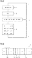
- control device 9 cyclically carries out steps S1 to S4 again and again.
- the control device 9 carries out the steps S1 to S4 in a strictly clocked manner, that is to say with a fixed cycle time T.
- the cycle time T is generally far below 1 s, in particular below 100 ms. For example, it can be 8 ms.
- the metal strip 1 can be cut as shown in 3 be divided into a number of sections 12. The subdivision is only virtual, i.e. purely mental. Sections 12 are in 3 partially supplemented with a small letter (a, b, etc.) in order to be able to distinguish them from one another if necessary.
- the arrow in 3 designates the transport direction of the metal strip 1.
- FIG 2 and also the other FIG each relate to a single cycle, ie a one-off execution of steps S1 to S4.
- rolling stand 2 is rolled as shown in 3 a single section 12 of the metal strip 1 is rolled.
- the currently rolled section 12 of the metal strip 1 is hereinafter denoted by reference numeral 12a.
- the previous cycle the previous section 12 of the metal strip 1 has been rolled.
- the following section 12 of the metal strip 1 is rolled.
- Analogous statements apply to the other sections 12 of the metal strip 1.
- the control device 9 receives the thickness values d1, d2 recorded in each case and, if applicable, also the values recorded in each case for the entry speed v1 and the exit speed v2.
- the section 12a is rolled.
- the detected thickness value d1 relates to another section 12 of the metal strip 1, which is rolled after the section 12 of the metal strip 1 that is currently being rolled.
- the thickness value d1 can relate to the section 12 of the metal strip 1 identified by the reference number 12b.
- the detected thickness value d2, on the other hand, relates to a section 12 of the metal strip 1 that has already been rolled, ie was rolled before the section 12 of the metal strip 1 that is currently being rolled.
- the thickness value d2 can relate to the section 12 of the metal strip 1 denoted by the reference symbol 12c.
- the detected speeds v1, v2 in turn relate to the currently rolled section 12a.
- step S2 the control device 9 selects a number of final thickness deviations ⁇ d2.
- the final thickness deviations ⁇ d2 selected in step S2 are those final thickness deviations ⁇ d2 which are evaluated in step S3 and, based on this, also in S4.
- the number of selected thickness deviations ⁇ d2 is equal to 1.
- the control device 9 therefore selects a single final thickness deviation ⁇ d2 in step S2.
- refinements of the present invention are also possible in which the control device 9 selects several final thickness deviations ⁇ d2 in step S2. In this case, each selected final thickness deviation ⁇ d2 is limited to one section 12 of a corresponding number of sections 12 of the metal strip 1 related.
- the selected final thickness deviation ⁇ d2' relates either to section 12a or to section 12c.
- Each individual final thickness deviation ⁇ d2 is the difference between a final thickness d2' of the metal strip 1 on the outlet side of the roll stand 2 and the associated target thickness d2* of the metal strip 1 on the outlet side of the roll stand 2.
- the respective final thickness d2' is therefore the corresponding thickness d2' of the metal strip 1 after rolling in the roll stand 2.
- the respective final thickness d2' relates to the corresponding section 12 of the metal strip 2.
- step S3 the control device 9 determines a number of target values s*, M2*, vU*, v3*, M3*, v4*, M4* for a corresponding number of actuators 13, 14, 3, 4.
- the control device 9 evaluates im Within the framework of determining the target values s*, M2*, vU*, v3*, M3*, v4*, M4*, the specified number of final thickness deviations ⁇ d2.
- step S4 the control device 9 sends the determined setpoint values s*, M2*, vU*, v3*, M3*, v4*, M4* to the actuators 13, 14, 3, 4 (more precisely: to the actuators 13, 14, 3, 4 upstream controllers).
- the setpoints s*, M2*, vU*, v3*, M3*, v4*, M4* can be basic setpoints, ie setpoints which completely or at least almost completely define a resulting setpoint for the corresponding actuator 13, 14, 3, 4 .
- these are often additional setpoints, ie setpoints that are added to such a basic setpoint or are added to such a basic setpoint.
- the number of actuators 13, 14, 3, 4 and the type of actuators 13, 14, 3, 4 can be selected as required.
- one of the actuators 13, 14, 3, 4 can be an adjustment device 13 of the roll stand 2 for setting a roll gap of the roll stand 2.
- the associated setpoint s* is a roll gap setpoint s*, which is output, for example, to a so-called HGC (hydraulic gap control).
- one of the actuators 13, 14, 3, 4 can be a drive 14 of the roll stand 2 for driving rolls of the roll stand 2.
- the associated desired value vU*, M2* is a circumferential roll speed vU* or a rolling torque M2*.
- one of the actuators 13, 14, 3, 4 can be the feed device 3.
- the associated setpoint value v3*, M3* is a setpoint speed v3* or a setpoint torque M3*.
- one of the actuators 13, 14, 3, 4 can be the discharge device 4.
- the associated setpoint value v4*, M4* is a setpoint speed v4* or a setpoint torque M4*.
- the actuators 13, 14, 3, 4 to include either the adjustment device 13 of the roll stand 2, the drive 14 of the roll stand 2 and the feed device 3, or the adjustment device 13 of the roll stand 2, the drive 14 of the roll stand 2 and the discharge device 4 include.
- the control device 9 determines as setpoints the setpoint s* for the roll gap and the setpoint M2* for the rolling torque or the setpoint vU* for the circumferential roll speed vU and furthermore either the setpoint v3* or M3* for the feed device 3 or alternatively the setpoint v4* or M4* for the discharge device 4.
- the core of the invention is the way in which the control device 9 in step S3 when determining the desired values s*, M2*, vU*, v3*, M3*, v4*, M4* the stated number of final thickness deviations ⁇ d2.
- This way is described below in connection with FIG 4 for determining the roll gap setpoint s* for the adjustment device 13 is explained in more detail.
- Analogous statements apply to the other actuators 3, 4, 14 and the other desired values M2*, vU*, v3*, M3*, v4*, M4*.
- the present invention will be explained in connection with a single final thickness deviation ⁇ d2. The same explanations apply to the utilization of several final thickness deviations ⁇ d2.
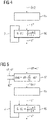
- the control device 9 comprises a regulator block 15 and a modification block 16.
- the division into the regulator block 15 and the modification block 16 takes place in order to be able to explain the present invention more simply.
- the controller block 15 and the modification block 16 can also be combined to form a common block.
- the order of the blocks 15, 16 can also be reversed with a corresponding adjustment of the variables fed to the respective block 15, 16 and the variables output by the respective block 15, 16.
- the regulator block 15 and the modification block 16 are implemented as software blocks by the control device 9, mostly due to the execution of the control program 10 .
- the controller block 15 is supplied with the final thickness deviation ⁇ d2.
- the controller block 15 uses a controller characteristic defined by the implementation of the controller block 15 to determine a provisional desired value s′*.
- the controller characteristic can be implemented, for example, in the manner of a P controller (ie a proportional controller), a PI controller (ie a proportional-integral controller), a controller structure implemented using an observer, etc.
- the controller block 15 as such can also be designed as in the prior art.
- the provisional desired value s′* is transmitted from the controller block 15 to the modification block 16.
- the modification block 16 modifies the provisional setpoint s'* and thus determines the (final) setpoint s*.
- - and this is the decisive factor - a description of the inverse frequency behavior of the adjusting device 13 is taken into account in the modification block 16 .
- the control device 9 is given a description that directly characterizes the frequency behavior of the adjustment device 13 .
- the frequency behavior of the adjustment device 13 can be determined on the basis of the description mentioned.
- the control device 9 therefore not only determines the desired value s* in a manner by which the corresponding inverse frequency behavior is taken into account. Rather, the control device 9 explicitly knows the corresponding inverse frequency behavior as such. Parameters that define the inverse frequency behavior are therefore known to the control device 9 . This is explained in more detail below for the roll stand 2 and its employment.
- the roll stand 2 can be modeled in various ways. In the simplest case, roll stand 2 is modeled as a PT1 element. Alternatively, higher-order modeling can be considered. The modeling describes the roll stand 2 as such, optionally including its control (HGC).
- HGC its control
- the frequency behavior of the roll stand 2 can be described, for example, by a transfer function.
- G the transfer function as such is denoted by G, as is common practice.
- L denotes the Laplace operator.
- this procedure is taken because the reference symbol s* has already been assigned, namely as a designation for the desired roll gap value. The actual roll gap value would therefore have to be provided with the reference symbol s in the usual way.
- the Laplace operator is usually also denoted by s. A use of the reference number s* for the roll gap setpoint and the reference character s for the Laplacian operator could therefore cause unnecessary confusion.
- the inverse transfer function G -1 (L) is modeled exactly, the modeled behavior of the roll stand 2 often becomes unstable. In some cases, even the behavior of the real roll stand 2 become unstable. For example, the inverse of a PT1 element results in a PD element. A PD element amplifies high frequencies extremely. Also, the theoretically determinable output signal of a PD element cannot be implemented in reality. The reason for this are adjustment limits of the hiring device 13. To ensure stability and feasibility, the denominator polynomial of the inverse transfer function G -1 (L) is therefore expanded by a component that is proportional to the highest power of L in the numerator of the inverse transfer function G -1 (L ) is. This approach is known to those skilled in the art.
- the modification block 16 thus corresponds to the inverse model.
- the modification block 16 or the inverse model describes the inverse frequency behavior of the adjusting device 13. Transport times, constant dead times and the like can be within or taken into account outside of the modification block 16.
- the selected final thickness deviation ⁇ d2 of the corresponding section 12 of the metal strip 1 is supplied to the modification block 16-clocked with the cycle time T.
- the control device 9 uses the modification block 16 to determine the target value s* for the adjusting device 13 while also taking into account an internal state Z of the inverse model 16 and outputs the target value s* to the adjusting device 13 .
- the control device 9 updates the internal state Z using the selected final thickness deviation ⁇ d2 and the previous internal state Z of the modification block 16 .
- the internal state Z must be taken into account and the internal state Z must be tracked, since otherwise the modification block 16 would not be able to store any knowledge of the previous course of the final thickness deviation ⁇ d2 and therefore could not model any frequency behavior, only purely proportional behavior.
- the state Z can alternatively be a scalar or a vector quantity.
- a determination block 17 is arranged upstream of the controller block 15 .
- the determination block 17 is implemented by the control device 9 - analogously to the controller block 15 and the modification block 16 - mostly due to the execution of the control program 10 as a software block.
- the software block 17 is supplied with a final entry-side thickness d1'.
- the final upstream thickness is d1' based on that section 12 of the metal strip 1 which is rolled in the respective cycle, ie the section 12a.
- the final thickness d1′ on the inlet side is directly identical to a thickness d1 recorded on the inlet side, ie the thickness d1 that was recorded by means of the measuring device 5 on the inlet side of the roll stand 2 for the same section 12 of the metal strip 1 .
- the entry-side thickness d1 was recorded in an earlier cycle.
- the determination block 18 also implements a transport model which models the transport of a section 12 from the location of the detection device 5 to the rolling stand 2 .
- the determination block 17 is also supplied with the current entry speed v1 and the current exit speed v2. These values can be, for example, the measured values recorded in the respective cycle using the measuring devices 6 and 8 . Finally, the determination block 17 is supplied with the desired value d2* for the thickness of the metal strip 1 on the outlet side, ie the desired thickness d2*.
- the final thickness deviation ⁇ d2 determined is related to the section 12a of the metal strip 1 which is currently being rolled in the roll stand 2 .
- mass flow control is thus implemented.
- the determination block 17 is replaced by another determination block 18.
- the determination block 18 is implemented by the control device 9--similarly to the determination block 17--as a software block as a rule on the basis of the execution of the control program 10.
- the determination block 18 includes a transport model 19 and a computing block 20.
- the transport model 19 is used to model the path of sections 12 after passing the detection device 5.
- the final thickness d1' on the input side is also determined. This determination is made by filtering several thicknesses d1 recorded on the entry side of the roll stand 2 . this is in 6 indicated by the fact that the transport model 19 implements a filter curve as a filter function.
- the final thickness d1' on the input side is supplied to the computing block 20, which—similar to the determination block 17—determines the final thickness deviation ⁇ d2 using the mass flow equation.
- the filtering of the transport model 19 is generally a low-pass filtering, by means of which high-frequency fluctuations are filtered out. It is preferably a zero-phase filtering.
- FIG 7 is the final thickness deviation ⁇ d2 on a section 12c of the metal strip 1 which has already been rolled before the currently rolled section 12a of the metal strip 1.
- controller block 15, as shown in FIG 7 a value is supplied as the final thickness deviation ⁇ d2 which is determined directly and immediately using the measured value of the measuring device 7 .
- the difference between the setpoint thickness d2* and a final thickness d2' related to the outlet side of the roll stand 2 can be determined in a computing block 21 and output to the controller block 15 as the final thickness deviation ⁇ d2.
- the calculation block 21 in the embodiment according to FIG 7 supplied directly with the thickness d2 recorded for the section 12c on the outlet side.
- the arithmetic block 21 can also be implemented as a software block by the control device 9 due to the execution of the control program 10 .
- FIG 8 shows a modification of FIG 7 .
- the determined final thickness deviation ⁇ d2 is related to the section 12c of the metal strip 1 that has already been rolled in the roll stand 2.
- a feedback control is thus implemented.
- the arithmetic block 21 is replaced by a arithmetic block 22 and a downstream filter block 23 .
- the arithmetic block 22 can be connected in parallel with a further arithmetic block 24 .
- the blocks 22 and 23 and possibly also the block 24 are implemented by the control device 9--analogously to the other blocks---usually as a software block on the basis of the execution of the control program 10.
- a plurality of provisional thickness deviations ⁇ d2′ is supplied to the filter block 23—related to the respective cycle.
- the provisional thickness deviations ⁇ d2′ are based on a corresponding number of sections 12 of the metal strip 1 . They indicate the respective deviation of the thickness d2 of the corresponding section 12 of the metal strip 1 from the target thickness d2* on the outlet side.
- the filter block 23 determines the final thickness deviation ⁇ d2 by filtering the provisional thickness deviations ⁇ d2′ supplied in each case.
- the filtering is usually a low-pass filtering, by means of which high-frequency fluctuations are filtered out.
- the filter block 23 also implements a transport model, which models the transport of the sections 12 from the roll stand 2 to the location of the detection device 7 and, if necessary, beyond that.
- the filtering is as shown in 9 a zero phase filter. This is over 9 as can be seen from the fact that the sections 12 of the metal strip are marked there, the preliminary thickness deviations ⁇ d2′ of which are included in the determination of the final thickness deviation ⁇ d2. As can be seen, the provisional thickness deviations ⁇ d2′ of sections 12d go into the determination on the one hand. Although these sections 12d have already been rolled, they were rolled after the section 12c to which the final thickness deviation ⁇ d2 is related. Section 12a may be one of sections 12d. Sections 12d are located, as in 9 shown, as a rule in front of the measuring device 7, have therefore not yet passed the measuring device 7.
- provisional thickness deviations ⁇ d2′ which relate to sections 12e of the metal strip 1, are generally included in the determination of the final thickness deviation ⁇ d2 as part of the zero-phase filtering. These sections 12e are not only already rolled, but have even been rolled before the section 12c to which the final thickness deviation ⁇ d2 is related. The sections 12e are therefore generally located behind the measuring device 7, ie they have already passed the measuring device 7. Finally, the determination of the final thickness deviation ⁇ d2 also includes the provisional thickness deviation ⁇ d2′ of section 12c, whose outlet-side thickness d2 is in the respective Cycle is just detected by the measuring device 7.
- the control device 9 determines the corresponding provisional thickness deviations ⁇ d2′ by means of the computing block 22 using the mass flow equation.
- a respectively corresponding final thickness d1' on the inlet side of the corresponding section 12d is therefore included in the determination of the respective provisional thickness deviation ⁇ d2'.
- the entry speed v1 valid for the respective section 12d and the exit speed v2 valid for the respective section 12d are included in the determination of the respective provisional thickness deviation ⁇ d2′.
- the corresponding speeds v1, v2 can be readily known to the control device 9 since the sections 12d have already been rolled.
- the corresponding final upstream calipers d1' correspond directly to the calipers d1 recorded for sections 12d. It is also possible for the control device 9--in each case for the respective section 12d--to determine the respective final inlet-side thickness d1' by filtering a plurality of thicknesses d1 recorded on the inlet side of the roll stand 2. The determinations can be made in the same manner as discussed above for mass flow control (MFC).
- MFC mass flow control
- the same procedure can be used for the provisional thickness deviations ⁇ d2′ of the sections 12e.
- the computing block 24 can be omitted.
- a measured value for the outlet-side thickness d2 is already available for the provisional thickness deviations ⁇ d2′ of the sections 12e.
- the control device 9 for determining the corresponding provisional thickness deviations ⁇ d2' evaluates the measured value recorded in each case.
- only the difference between the respective measured value d2 and the target thickness d2* on the outlet side has to be formed in the same block 24 .
- the section 12c can be treated as one of the sections 12d or as one of the sections 12e as required, as far as the determination of its preliminary thickness deviation ⁇ d2 is concerned, the latter being preferred.
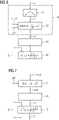
- the controller comprises three main blocks 25 to 27.
- the main block 25 implements an FBC.
- the FBC can be designed in particular as above in connection with the 7 to 9 was explained, so realize one of these configurations.
- the main block 26 implements an MFC.
- the MFC can in particular be designed as described above in connection with the 5 and 6 was explained, so realize one of these configurations.
- the FFC compensates for incoming thickness errors. In particular, it can be designed as in the earlier European patent application already mentioned 20184420.6 of Primetals Technologies Germany GmbH. However, other configurations of the FFC are also possible.
- Each of the main blocks 25 to 27 determines a respective setpoint. As a rule, this is a respective additional setpoint.
- the additional setpoints can be added to one another in a corresponding node 28 and--if necessary--to a base setpoint.
- the output signal of node 28 serves as an input signal for the adjustment device 13 and its control (HGC).
- the control device 9 it is possible for the control device 9 to set several target values s*, M2*, vU*, v3*, M3*, v4*, M4* for several actuators 13, 14, 3, 4 determined.
- several target values s*, M2*, vU*, v3*, M3*, v4*, M4* for several actuators 13, 14, 3, 4 it may be necessary to use individual target values s*, M2*, vU*, v3*, M3*, v4*, M4* in time to ensure a synchronous reaction of the various actuators 13, 14, 3, 4. This is known and familiar to those skilled in the art and readily implementable. It therefore does not need to be explained in detail.
- the present invention has many advantages. In particular, an almost complete correction of both inlet-side thickness deviations and outlet-side thickness deviations ⁇ d2 results in a simple manner. This applies in particular if not only an MFC and/or an FBC is implemented in a manner according to the invention, but both an MFC and an FBC are implemented in a manner according to the invention and, furthermore, an FFC is also implemented in this way is explained in European patent application 20184420.6. Furthermore, commissioning can be accelerated.
Landscapes
- Engineering & Computer Science (AREA)
- Mechanical Engineering (AREA)
- Physics & Mathematics (AREA)
- General Physics & Mathematics (AREA)
- Automation & Control Theory (AREA)
- Control Of Metal Rolling (AREA)
Priority Applications (3)
| Application Number | Priority Date | Filing Date | Title |
|---|---|---|---|
| EP20198745.0A EP3974073B2 (fr) | 2020-09-28 | 2020-09-28 | Laminage en fonction de la réponse de fréquence |
| US17/485,590 US20220097112A1 (en) | 2020-09-28 | 2021-09-27 | Rolling with allowance for frequency response |
| CN202111144325.3A CN114273440B (zh) | 2020-09-28 | 2021-09-28 | 在考虑频率行为下的轧制 |
Applications Claiming Priority (1)
| Application Number | Priority Date | Filing Date | Title |
|---|---|---|---|
| EP20198745.0A EP3974073B2 (fr) | 2020-09-28 | 2020-09-28 | Laminage en fonction de la réponse de fréquence |
Publications (4)
| Publication Number | Publication Date |
|---|---|
| EP3974073A1 true EP3974073A1 (fr) | 2022-03-30 |
| EP3974073B1 EP3974073B1 (fr) | 2023-07-19 |
| EP3974073C0 EP3974073C0 (fr) | 2023-07-19 |
| EP3974073B2 EP3974073B2 (fr) | 2026-05-20 |
Family
ID=72665147
Family Applications (1)
| Application Number | Title | Priority Date | Filing Date |
|---|---|---|---|
| EP20198745.0A Active EP3974073B2 (fr) | 2020-09-28 | 2020-09-28 | Laminage en fonction de la réponse de fréquence |
Country Status (3)
| Country | Link |
|---|---|
| US (1) | US20220097112A1 (fr) |
| EP (1) | EP3974073B2 (fr) |
| CN (1) | CN114273440B (fr) |
Citations (5)
| Publication number | Priority date | Publication date | Assignee | Title |
|---|---|---|---|---|
| JPS5868414A (ja) | 1981-10-20 | 1983-04-23 | Sumitomo Metal Ind Ltd | 入側厚み計を用いた板厚制御方法 |
| EP0435595A2 (fr) | 1989-12-25 | 1991-07-03 | Ishikawajima-Harima Jukogyo Kabushiki Kaisha | Système de vÀ©rification de l'épaisseur pour un laminoir |
| EP1488863A2 (fr) * | 2003-06-20 | 2004-12-22 | ABB PATENT GmbH | Système et procédé pour l'optimisation du réglage de la qualité de l'épaisseur dans un processus de laminage |
| WO2016151855A1 (fr) * | 2015-03-26 | 2016-09-29 | 東芝三菱電機産業システム株式会社 | Dispositif de régulation d'épaisseur de tôle pour matériau laminé |
| EP3332883A1 (fr) | 2016-12-09 | 2018-06-13 | Honeywell International Inc. | Capteur inférentiel basé sur un modèle de contrôle de l'épaisseur de métaux |
Family Cites Families (16)
| Publication number | Priority date | Publication date | Assignee | Title |
|---|---|---|---|---|
| SU554025A1 (ru) * | 1976-01-19 | 1977-04-15 | Уральский Завод Тяжелого Машиностроения Имени С.Орджоникидзе | Устройство дл формировани сигнала отклонени толщины прокатываемой полосы от заданного значени |
| US4531392A (en) * | 1984-03-19 | 1985-07-30 | Aluminum Company Of America | Phase compensator for gauge control using estimate of roll eccentricity |
| US4656854A (en) | 1985-09-06 | 1987-04-14 | Aluminum Company Of America | Rolling mill eccentricity compensation using measurement of sheet tension |
| JPH0732926B2 (ja) | 1990-11-30 | 1995-04-12 | 住友軽金属工業株式会社 | 圧延機における板厚制御方法 |
| JP3171212B2 (ja) | 1992-04-24 | 2001-05-28 | 川崎製鉄株式会社 | タンデム圧延機及びタンデム圧延機の板厚異常原因推定方法 |
| JP3316992B2 (ja) † | 1993-12-27 | 2002-08-19 | 株式会社日立製作所 | 制御装置,制御方法及び圧延機の制御装置並びに圧延機の制御方法 |
| JPH08323408A (ja) | 1995-05-31 | 1996-12-10 | Kawasaki Steel Corp | タンデム圧延機における異常圧延状態回避方法および装置 |
| FR2735046B1 (fr) * | 1995-06-08 | 1997-07-11 | Lorraine Laminage | Procede de laminage a froid avec compensation d'ovalisation des cylindres de laminage. |
| KR0158582B1 (ko) * | 1995-08-11 | 1999-01-15 | 김종진 | 열연강판의 단주기 두께편차 제어장치 |
| US6263714B1 (en) * | 1999-12-27 | 2001-07-24 | Telepro, Inc. | Periodic gauge deviation compensation system |
| FR2853570B1 (fr) | 2003-04-11 | 2005-07-01 | Vai Clecim | Procede et dispositif de regulation de l'epaisseur d'un produit lamine |
| DE102004039829B3 (de) | 2004-08-17 | 2006-03-09 | Siemens Ag | Verfahren zur Kompensation periodischer Störungen |
| FR2887480B1 (fr) * | 2005-06-23 | 2007-09-21 | Vai Clecim Soc Par Actions Sim | Procede et dispositif de regulation de l'epaisseur d'un produit lamine en sortie d'une installation de laminage en tandem |
| DE102006008574A1 (de) † | 2006-02-22 | 2007-08-30 | Siemens Ag | Verfahren zur Unterdrückung des Einflusses von Walzenexzentrizitäten |
| EP2298461A1 (fr) * | 2009-09-17 | 2011-03-23 | Siemens Aktiengesellschaft | Train de laminoir à froid doté d'une régulation du débit massique sur une cage de laminoir |
| EP2998040A1 (fr) * | 2014-09-17 | 2016-03-23 | Primetals Technologies Germany GmbH | Réglage de largeur d'une ligne de fabrication |
-
2020
- 2020-09-28 EP EP20198745.0A patent/EP3974073B2/fr active Active
-
2021
- 2021-09-27 US US17/485,590 patent/US20220097112A1/en not_active Abandoned
- 2021-09-28 CN CN202111144325.3A patent/CN114273440B/zh active Active
Patent Citations (5)
| Publication number | Priority date | Publication date | Assignee | Title |
|---|---|---|---|---|
| JPS5868414A (ja) | 1981-10-20 | 1983-04-23 | Sumitomo Metal Ind Ltd | 入側厚み計を用いた板厚制御方法 |
| EP0435595A2 (fr) | 1989-12-25 | 1991-07-03 | Ishikawajima-Harima Jukogyo Kabushiki Kaisha | Système de vÀ©rification de l'épaisseur pour un laminoir |
| EP1488863A2 (fr) * | 2003-06-20 | 2004-12-22 | ABB PATENT GmbH | Système et procédé pour l'optimisation du réglage de la qualité de l'épaisseur dans un processus de laminage |
| WO2016151855A1 (fr) * | 2015-03-26 | 2016-09-29 | 東芝三菱電機産業システム株式会社 | Dispositif de régulation d'épaisseur de tôle pour matériau laminé |
| EP3332883A1 (fr) | 2016-12-09 | 2018-06-13 | Honeywell International Inc. | Capteur inférentiel basé sur un modèle de contrôle de l'épaisseur de métaux |
Also Published As
| Publication number | Publication date |
|---|---|
| EP3974073B1 (fr) | 2023-07-19 |
| EP3974073C0 (fr) | 2023-07-19 |
| US20220097112A1 (en) | 2022-03-31 |
| CN114273440A (zh) | 2022-04-05 |
| CN114273440B (zh) | 2025-08-08 |
| EP3974073B2 (fr) | 2026-05-20 |
Similar Documents
| Publication | Publication Date | Title |
|---|---|---|
| DE19963186B4 (de) | Verfahren zur Steuerung und/oder Regelung der Kühlstrecke einer Warmbandstrasse zum Walzen von Metallband und zugehörige Vorrichtung | |
| EP3107666B1 (fr) | Précommande simple du pas de filetage d'un ébaucheur | |
| EP2697001B1 (fr) | Procédé de commande pour train de laminage | |
| EP2691188B1 (fr) | Procédé permettant de faire fonctionner un train de laminoir | |
| EP2252416B1 (fr) | Procédé de régulation pour un train de laminoir à froid avec régulation intégrale du débit massique | |
| EP4061552B1 (fr) | Procédé, dipositif de contrôle et laminoir pour le réglage d'une température de sortie d'une bande métallique quittant un train de laminage | |
| EP2697002B1 (fr) | Procédé de commande pour train de laminoir | |
| EP2162245B1 (fr) | Laminage d'un feuillard dans un laminoir en utilisant la dernière cage du laminoir comme réducteur de traction | |
| EP3461567A1 (fr) | Dispositif de réglage de planéité doté du dispositif d'optimisation | |
| WO2012034875A2 (fr) | Procédé de détermination de grandeurs de commande d'un train de laminoir comportant plusieurs cages pour laminer une bande de métal | |
| EP3208673B1 (fr) | Étalonnage en ligne d'une emprise de laminage d'une cage de laminoir | |
| DE102014215397B4 (de) | Bandlageregelung mit optimierter Reglerauslegung | |
| EP3194087B1 (fr) | Réglage de largeur d'une ligne de fabrication | |
| EP2200763B1 (fr) | Adaptation d'un régulateur dans un laminoir sur la base de la dispersion d'une grandeur réelle d'un produit laminé | |
| DE3303829A1 (de) | Verfahren und vorrichtung zur steuerung eines kontinuierlich arbeitenden walzwerks | |
| EP3231522B1 (fr) | Controle robuste de tension de bande | |
| EP3632583A1 (fr) | Réglage découplé du contour et planéité d'une bande métallique | |
| EP3974073B1 (fr) | Laminage en fonction de la réponse de fréquence | |
| EP2483004A1 (fr) | Procédé de détermination, basée sur un modèle, de valeurs théoriques pour les actionneurs symétriques et asymétriques des cages d'un laminoir à chaud à larges bandes | |
| EP2477763B1 (fr) | Train de laminoir à froid doté d'une régulation du débit massique sur une cage de laminoir | |
| EP3936248B1 (fr) | Laminage en fonction de la réponse de fréquence | |
| EP4103339B1 (fr) | Détermination de la sensibilité d'une grandeur cible d'une matière à laminer pour un paramètre de fonctionnement d'un train de laminage à chaud | |
| DE112022003044T5 (de) | Kühlsystem für ein walzwerk | |
| EP4442379B1 (fr) | Procédé de fonctionnement d'une installation de laminage continu à cage de compression | |
| EP4119247B1 (fr) | Prise en compte de la densité dépendante de l'état lors de la résolution d'une équation de conduction thermique |
Legal Events
| Date | Code | Title | Description |
|---|---|---|---|
| PUAI | Public reference made under article 153(3) epc to a published international application that has entered the european phase |
Free format text: ORIGINAL CODE: 0009012 |
|
| STAA | Information on the status of an ep patent application or granted ep patent |
Free format text: STATUS: THE APPLICATION HAS BEEN PUBLISHED |
|
| AK | Designated contracting states |
Kind code of ref document: A1 Designated state(s): AL AT BE BG CH CY CZ DE DK EE ES FI FR GB GR HR HU IE IS IT LI LT LU LV MC MK MT NL NO PL PT RO RS SE SI SK SM TR |
|
| STAA | Information on the status of an ep patent application or granted ep patent |
Free format text: STATUS: REQUEST FOR EXAMINATION WAS MADE |
|
| 17P | Request for examination filed |
Effective date: 20220930 |
|
| RBV | Designated contracting states (corrected) |
Designated state(s): AL AT BE BG CH CY CZ DE DK EE ES FI FR GB GR HR HU IE IS IT LI LT LU LV MC MK MT NL NO PL PT RO RS SE SI SK SM TR |
|
| GRAP | Despatch of communication of intention to grant a patent |
Free format text: ORIGINAL CODE: EPIDOSNIGR1 |
|
| STAA | Information on the status of an ep patent application or granted ep patent |
Free format text: STATUS: GRANT OF PATENT IS INTENDED |
|
| INTG | Intention to grant announced |
Effective date: 20230301 |
|
| GRAS | Grant fee paid |
Free format text: ORIGINAL CODE: EPIDOSNIGR3 |
|
| GRAA | (expected) grant |
Free format text: ORIGINAL CODE: 0009210 |
|
| STAA | Information on the status of an ep patent application or granted ep patent |
Free format text: STATUS: THE PATENT HAS BEEN GRANTED |
|
| AK | Designated contracting states |
Kind code of ref document: B1 Designated state(s): AL AT BE BG CH CY CZ DE DK EE ES FI FR GB GR HR HU IE IS IT LI LT LU LV MC MK MT NL NO PL PT RO RS SE SI SK SM TR |
|
| REG | Reference to a national code |
Ref country code: GB Ref legal event code: FG4D Free format text: NOT ENGLISH |
|
| REG | Reference to a national code |
Ref country code: CH Ref legal event code: EP |
|
| REG | Reference to a national code |
Ref country code: DE Ref legal event code: R096 Ref document number: 502020004233 Country of ref document: DE |
|
| REG | Reference to a national code |
Ref country code: IE Ref legal event code: FG4D Free format text: LANGUAGE OF EP DOCUMENT: GERMAN |
|
| U01 | Request for unitary effect filed |
Effective date: 20230720 |
|
| U07 | Unitary effect registered |
Designated state(s): AT BE BG DE DK EE FI FR IT LT LU LV MT NL PT SE SI Effective date: 20230726 |
|
| REG | Reference to a national code |
Ref country code: LT Ref legal event code: MG9D |
|
| U20 | Renewal fee for the european patent with unitary effect paid |
Year of fee payment: 4 Effective date: 20231106 |
|
| PG25 | Lapsed in a contracting state [announced via postgrant information from national office to epo] |
Ref country code: GR Free format text: LAPSE BECAUSE OF FAILURE TO SUBMIT A TRANSLATION OF THE DESCRIPTION OR TO PAY THE FEE WITHIN THE PRESCRIBED TIME-LIMIT Effective date: 20231020 |
|
| PG25 | Lapsed in a contracting state [announced via postgrant information from national office to epo] |
Ref country code: IS Free format text: LAPSE BECAUSE OF FAILURE TO SUBMIT A TRANSLATION OF THE DESCRIPTION OR TO PAY THE FEE WITHIN THE PRESCRIBED TIME-LIMIT Effective date: 20231119 |
|
| PG25 | Lapsed in a contracting state [announced via postgrant information from national office to epo] |
Ref country code: RS Free format text: LAPSE BECAUSE OF FAILURE TO SUBMIT A TRANSLATION OF THE DESCRIPTION OR TO PAY THE FEE WITHIN THE PRESCRIBED TIME-LIMIT Effective date: 20230719 Ref country code: NO Free format text: LAPSE BECAUSE OF FAILURE TO SUBMIT A TRANSLATION OF THE DESCRIPTION OR TO PAY THE FEE WITHIN THE PRESCRIBED TIME-LIMIT Effective date: 20231019 Ref country code: IS Free format text: LAPSE BECAUSE OF FAILURE TO SUBMIT A TRANSLATION OF THE DESCRIPTION OR TO PAY THE FEE WITHIN THE PRESCRIBED TIME-LIMIT Effective date: 20231119 Ref country code: HR Free format text: LAPSE BECAUSE OF FAILURE TO SUBMIT A TRANSLATION OF THE DESCRIPTION OR TO PAY THE FEE WITHIN THE PRESCRIBED TIME-LIMIT Effective date: 20230719 Ref country code: GR Free format text: LAPSE BECAUSE OF FAILURE TO SUBMIT A TRANSLATION OF THE DESCRIPTION OR TO PAY THE FEE WITHIN THE PRESCRIBED TIME-LIMIT Effective date: 20231020 |
|
| PG25 | Lapsed in a contracting state [announced via postgrant information from national office to epo] |
Ref country code: PL Free format text: LAPSE BECAUSE OF FAILURE TO SUBMIT A TRANSLATION OF THE DESCRIPTION OR TO PAY THE FEE WITHIN THE PRESCRIBED TIME-LIMIT Effective date: 20230719 |
|
| REG | Reference to a national code |
Ref country code: DE Ref legal event code: R026 Ref document number: 502020004233 Country of ref document: DE |
|
| PG25 | Lapsed in a contracting state [announced via postgrant information from national office to epo] |
Ref country code: ES Free format text: LAPSE BECAUSE OF FAILURE TO SUBMIT A TRANSLATION OF THE DESCRIPTION OR TO PAY THE FEE WITHIN THE PRESCRIBED TIME-LIMIT Effective date: 20230719 |
|
| PLBI | Opposition filed |
Free format text: ORIGINAL CODE: 0009260 |
|
| PG25 | Lapsed in a contracting state [announced via postgrant information from national office to epo] |
Ref country code: SM Free format text: LAPSE BECAUSE OF FAILURE TO SUBMIT A TRANSLATION OF THE DESCRIPTION OR TO PAY THE FEE WITHIN THE PRESCRIBED TIME-LIMIT Effective date: 20230719 Ref country code: RO Free format text: LAPSE BECAUSE OF FAILURE TO SUBMIT A TRANSLATION OF THE DESCRIPTION OR TO PAY THE FEE WITHIN THE PRESCRIBED TIME-LIMIT Effective date: 20230719 Ref country code: ES Free format text: LAPSE BECAUSE OF FAILURE TO SUBMIT A TRANSLATION OF THE DESCRIPTION OR TO PAY THE FEE WITHIN THE PRESCRIBED TIME-LIMIT Effective date: 20230719 Ref country code: CZ Free format text: LAPSE BECAUSE OF FAILURE TO SUBMIT A TRANSLATION OF THE DESCRIPTION OR TO PAY THE FEE WITHIN THE PRESCRIBED TIME-LIMIT Effective date: 20230719 Ref country code: SK Free format text: LAPSE BECAUSE OF FAILURE TO SUBMIT A TRANSLATION OF THE DESCRIPTION OR TO PAY THE FEE WITHIN THE PRESCRIBED TIME-LIMIT Effective date: 20230719 |
|
| REG | Reference to a national code |
Ref country code: CH Ref legal event code: PL |
|
| PLAX | Notice of opposition and request to file observation + time limit sent |
Free format text: ORIGINAL CODE: EPIDOSNOBS2 |
|
| 26 | Opposition filed |
Opponent name: SMS GROUP GMBH Effective date: 20240419 |
|
| PG25 | Lapsed in a contracting state [announced via postgrant information from national office to epo] |
Ref country code: MC Free format text: LAPSE BECAUSE OF FAILURE TO SUBMIT A TRANSLATION OF THE DESCRIPTION OR TO PAY THE FEE WITHIN THE PRESCRIBED TIME-LIMIT Effective date: 20230719 |
|
| REG | Reference to a national code |
Ref country code: IE Ref legal event code: MM4A |
|
| PG25 | Lapsed in a contracting state [announced via postgrant information from national office to epo] |
Ref country code: IE Free format text: LAPSE BECAUSE OF NON-PAYMENT OF DUE FEES Effective date: 20230928 |
|
| PG25 | Lapsed in a contracting state [announced via postgrant information from national office to epo] |
Ref country code: CH Free format text: LAPSE BECAUSE OF NON-PAYMENT OF DUE FEES Effective date: 20230930 |
|
| PG25 | Lapsed in a contracting state [announced via postgrant information from national office to epo] |
Ref country code: IE Free format text: LAPSE BECAUSE OF NON-PAYMENT OF DUE FEES Effective date: 20230928 Ref country code: CH Free format text: LAPSE BECAUSE OF NON-PAYMENT OF DUE FEES Effective date: 20230930 |
|
| PLBB | Reply of patent proprietor to notice(s) of opposition received |
Free format text: ORIGINAL CODE: EPIDOSNOBS3 |
|
| U20 | Renewal fee for the european patent with unitary effect paid |
Year of fee payment: 5 Effective date: 20240930 |
|
| GBPC | Gb: european patent ceased through non-payment of renewal fee |
Effective date: 20240928 |
|
| PG25 | Lapsed in a contracting state [announced via postgrant information from national office to epo] |
Ref country code: GB Free format text: LAPSE BECAUSE OF NON-PAYMENT OF DUE FEES Effective date: 20240928 |
|
| PG25 | Lapsed in a contracting state [announced via postgrant information from national office to epo] |
Ref country code: CY Free format text: LAPSE BECAUSE OF FAILURE TO SUBMIT A TRANSLATION OF THE DESCRIPTION OR TO PAY THE FEE WITHIN THE PRESCRIBED TIME-LIMIT; INVALID AB INITIO Effective date: 20200928 |
|
| PG25 | Lapsed in a contracting state [announced via postgrant information from national office to epo] |
Ref country code: HU Free format text: LAPSE BECAUSE OF FAILURE TO SUBMIT A TRANSLATION OF THE DESCRIPTION OR TO PAY THE FEE WITHIN THE PRESCRIBED TIME-LIMIT; INVALID AB INITIO Effective date: 20200928 |
|
| U20 | Renewal fee for the european patent with unitary effect paid |
Year of fee payment: 6 Effective date: 20250930 |
|
| PG25 | Lapsed in a contracting state [announced via postgrant information from national office to epo] |
Ref country code: TR Free format text: LAPSE BECAUSE OF FAILURE TO SUBMIT A TRANSLATION OF THE DESCRIPTION OR TO PAY THE FEE WITHIN THE PRESCRIBED TIME-LIMIT Effective date: 20230719 |
|
| PUAH | Patent maintained in amended form |
Free format text: ORIGINAL CODE: 0009272 |
|
| STAA | Information on the status of an ep patent application or granted ep patent |
Free format text: STATUS: PATENT MAINTAINED AS AMENDED |
|
| REG | Reference to a national code |
Ref country code: CH Ref legal event code: M12 Free format text: ST27 STATUS EVENT CODE: U-0-0-M10-M12 (AS PROVIDED BY THE NATIONAL OFFICE) Effective date: 20260423 |
|
| 27A | Patent maintained in amended form |
Effective date: 20260520 |
|
| AK | Designated contracting states |
Kind code of ref document: B2 Designated state(s): AL AT BE BG CH CY CZ DE DK EE ES FI FR GB GR HR HU IE IS IT LI LT LU LV MC MK MT NL NO PL PT RO RS SE SI SK SM TR |