EP4119247B1 - Prise en compte de la densité dépendante de l'état lors de la résolution d'une équation de conduction thermique - Google Patents
Prise en compte de la densité dépendante de l'état lors de la résolution d'une équation de conduction thermique Download PDFInfo
- Publication number
- EP4119247B1 EP4119247B1 EP21185929.3A EP21185929A EP4119247B1 EP 4119247 B1 EP4119247 B1 EP 4119247B1 EP 21185929 A EP21185929 A EP 21185929A EP 4119247 B1 EP4119247 B1 EP 4119247B1
- Authority
- EP
- European Patent Office
- Prior art keywords
- rolling stock
- treatment
- control device
- density
- heat conduction
- Prior art date
- Legal status (The legal status is an assumption and is not a legal conclusion. Google has not performed a legal analysis and makes no representation as to the accuracy of the status listed.)
- Active
Links
Images


Classifications
-
- B—PERFORMING OPERATIONS; TRANSPORTING
- B21—MECHANICAL METAL-WORKING WITHOUT ESSENTIALLY REMOVING MATERIAL; PUNCHING METAL
- B21B—ROLLING OF METAL
- B21B37/00—Control devices or methods specially adapted for metal-rolling mills or the work produced thereby
-
- C—CHEMISTRY; METALLURGY
- C21—METALLURGY OF IRON
- C21D—MODIFYING THE PHYSICAL STRUCTURE OF FERROUS METALS; GENERAL DEVICES FOR HEAT TREATMENT OF FERROUS OR NON-FERROUS METALS OR ALLOYS; MAKING METAL MALLEABLE, e.g. BY DECARBURISATION OR TEMPERING
- C21D9/00—Heat treatment, e.g. annealing, hardening, quenching or tempering, adapted for particular articles; Furnaces therefor
-
- B—PERFORMING OPERATIONS; TRANSPORTING
- B21—MECHANICAL METAL-WORKING WITHOUT ESSENTIALLY REMOVING MATERIAL; PUNCHING METAL
- B21B—ROLLING OF METAL
- B21B37/00—Control devices or methods specially adapted for metal-rolling mills or the work produced thereby
- B21B37/74—Temperature control, e.g. by cooling or heating the rolls or the product
Definitions
- the present invention is further based on a control program for a control device of a treatment device for treating a rolled metal product, wherein the control program comprises machine code which can be processed by the control device, wherein the processing of the machine code by the control device causes the control device operates the treatment facility in accordance with such a treatment process.
- the present invention is further based on a control device of a treatment device for treating a rolled metal product, wherein the control device is programmed with such a control program, so that the control device operates the treatment device according to such a treatment method.
- a heat conduction equation is often used for proper modeling.
- the heat conduction equation is a differential equation that must be solved iteratively in small time steps.
- the heat conduction equation can be applied in different ways.
- Heat conduction equations are known in various forms. For example, it is known to set the heat conduction equation one-dimensionally or three-dimensionally. In the case of a one-dimensional approach, the heat conduction equation is only solved in the thickness direction of the flat rolled stock. The heat flow in the longitudinal direction and in the width direction is neglected. Below - in the sense of an incomplete list - some possible one-dimensional approaches for the heat conduction equation are listed and explained. The corresponding three-dimensional approaches are not explained separately, but are (at least mostly) given in the state of the art.
- Equation 1 The difference to equation 1 is that the heat capacity c P is now temperature-dependent and thus indirectly variable over time and a non-linear behavior of the rolling stock can be modeled.
- the thermal conductivity can be state-dependent. This approach is also explained in the above-mentioned textbook by Aslak Tveito and Ragnar Winther. It is non-linear and is also based on temperature.
- H is the enthalpy and p is a phase state.
- the phase state can be scalar or vectorial.
- Q is used to model heat sources or heat sinks.
- This approach is used, for example, in the EP 1 397 523 A1 , the EP 1 576 429 A1 and the EP 1 711 868 B1 explained.
- This approach is non-linear, works with enthalpy and phase transformation as well as with sources.
- Temperature is a quantity derived from enthalpy and the phase state. This approach can take heat sources and heat sinks into account.
- p is - as before - the density
- f i are fractions of phases
- ⁇ i are the densities of the phases.
- the heat conduction equation always includes (among other things) the density. This applies regardless of whether one of the approaches explained above or another approach is used for the heat conduction equation. It also applies regardless of whether the heat conduction equation is set to be one-dimensional or multidimensional, and regardless of whether the heat conduction equation is set to be linear or non-linear.
- the object of the present invention is to provide possibilities by means of which the state-dependent density of the rolling stock can be correctly taken into account and thus the accuracy in solving the heat conduction equation can be improved.
- the dependence of the heat conduction equation on the density of the rolling stock can be fully taken into account by the factor a or a'.
- the heat conduction equation is therefore independent of the density of the rolling stock.
- the factors a and a' will be derived later for a very specific heat conduction equation. However, they are completely independent of the specific heat conduction equation used. Any of the equations 1 to 4 can be used, even in their multidimensional form. Other heat conduction equations can also be used. If required, it is also possible to solve the heat conduction equation used with simultaneous coupling with a phase transformation equation and thus take into account the heat of transformation that occurs during the phase transformation.
- the coefficients xL, xB and xD must be known individually. However, the density is often isotropic. In this case, changes in density are also isotropic. Thus, only the density as such needs to be known. In this case, it is possible to determine the coefficients xL, xB and xD in such a way that they are equal to each other and their product is equal to the quotient of the density dependent on the respective thermal state of the rolling stock and the standardized density related to the predetermined thermal state of the rolling stock.
- the coefficient xL or the coefficient xB or the cube root of the density change could of course also be used (due to equality).
- the coefficient xD can be determined in such a way that it is equal to the cube root of the quotient of the density dependent on the respective thermal state of the rolling stock and the normalized density related to the predetermined thermal state of the rolling stock.
- the modelling of the temporal development of the thermal state of the rolling stock may be carried out offline.
- the modelling of the temporal development of the thermal state of the rolling stock is usually carried out online - for example as part of a setup calculation - or even in real time.
- the type of treatment can be as required.
- the rolling stock is rolled using the treatment device, so that the thickness of the rolling stock after the treatment device has acted on the rolling stock is smaller than before the treatment device has acted on the rolling stock.
- the thermal the condition of the rolling stock can be used, for example, to determine the forming resistance of the rolling stock and thus to determine the required rolling force.
- the treatment facility often has a purely thermal effect on the rolling stock without forming the rolling stock.
- a thermal effect on the rolling stock can, as required, be heating (e.g. inductive heating) before a roughing train or before a finishing train. It can also be an effect in which cooling occurs as an unavoidable side effect, for example when descaling the rolling stock. Above all, however, it can be intentional cooling. Examples of this could be inter-stand cooling (i.e. cooling between individual rolling processes in a multi-stand rolling mill) or cooling in a cooling section downstream of a rolling device.
- control program with the features of claim 6.
- processing of the control program causes the control device to operate the treatment device according to a treatment method according to the invention.
- control device with the features of claim 7.
- the control device is programmed with a control program according to the invention, so that the control device operates the treatment device according to a treatment method according to the invention.
- control device is designed as a control device according to the invention, so that the control device controls the treatment device according to a treatment method according to the invention.
- a treatment plant for rolling stock 1 has a treatment device 2.
- the rolling stock 1 can be influenced by means of the treatment device 2.
- the rolled product 1 consists of metal.
- the rolled product 1 usually consists of steel. However, it can also consist of another metal, for example aluminum or copper.
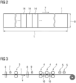
- the rolled product 1 extends - see FIG 2 - in a longitudinal direction over a Total length L and in a width direction over a total width B.
- the rolled stock 1 also extends in a thickness direction - see FIG 1 - over a thickness D.
- the thickness D is smaller than the width B, usually considerably smaller.
- the width B is usually smaller than the length L. Typical values for the thickness D are in the range of less than 1 mm to 250 mm, sometimes slightly more. Typical values for the width B are in the range of between 500 mm and 2500 mm, in some cases even slightly more.
- the length L is several meters, for example several 100 m or even up to over 1000 m.
- the rolled stock 1 is therefore a flat rolled stock 1.
- the rolled stock 1 is a hot rolled stock 1.
- the rolling stock 1 can be influenced at least essentially in the thickness direction. This will be explained below in connection with FIG 3 explained in more detail.
- the rolling stock 1 can first be pre-rolled in a roughing mill, then finish-rolled in a finishing train, then cooled in a cooling section downstream of the finishing train and finally wound into a coil.
- the roughing mill has at least one roughing stand 3 for pre-rolling the rolling stock 1.
- the finishing train has at least one finishing stand 4 for finish-rolling the rolling stock 1.
- the cooling section has at least one application device 5, by means of which the rolling stock 1 can be exposed to cooling water.
- a heating device 6 (in particular an induction heater) and/or a descaling device 7 can be arranged upstream of the roughing mill.
- a heating device 8 (in particular an induction heater) and/or a descaling device 9 can be arranged upstream of the finishing train.
- intermediate stand cooling systems 10 can also be arranged between the finishing stands 4, by means of which the rolling stock 1 between the individual finishing rolling stands 4 can be supplied with cooling water.
- Each of the components 3 to 10 mentioned can be a treatment device 2 in the sense of the present invention.
- the rolling stock 1 In the case of the rolling stands 3, 4, the rolling stock 1 is rolled. In this case, the thickness D of the rolling stock 1 after the treatment device 2, 3, 4 has acted on the rolling stock 1 is generally smaller than before the treatment device 2, 3, 4 has acted on the rolling stock 1. Equality is only given in exceptional cases if the rolling stock 1 passes through the treatment device 2, 3, 4 without being deformed.
- the heating devices 6, 8, the descaling devices 7, 9 and the inter-stand cooling systems 10 the action of the treatment device 2, 5 to 10 on the rolling stock 1 results in a purely thermal influence on the rolling stock 1 without deformation.
- the heating devices 6, 8, the purely thermal influence is a heating of the rolling stock 1.
- the descaling devices 7, 9 and the inter-stand cooling in 10 the purely thermal influence is a cooling of the rolling stock 1.
- the treatment facility 2 (and possibly other components of the treatment plant) are designed in accordance with FIG 1 controlled by a control device 11.
- the control device 11 is programmed with a control program 12.
- the control program 12 includes machine code 13, which can be processed by the control device 11.
- the programming of the control device 11 with the control program 12 (or equivalently the processing of the machine code 13 by the control device 11) causes the control device 11 to
- Treatment facility 2 operates according to a treatment process as described below - initially in connection with FIG 4 - is explained in more detail.
- the control device 11 is informed of an initial state ZA of the rolling stock 1.
- the initial state ZA may refer to the entire rolling stock 1. Alternatively, it may - see FIG 2 - refer to a single section 14 of the rolling stock 1. It is assumed below that the initial state ZA refers to a single section 14 of the rolling stock 1. This also represents the general case, since in the case of a uniform consideration of the entire rolling stock 1, only the number of sections 14 needs to be reduced accordingly, namely to a single section 14.
- the initial state ZA determines a thermal state of the section 14. In particular, it determines - directly or indirectly - at least the initial temperature T of the corresponding section 14. If necessary, a phase state p can also be determined in addition.
- the initial state ZA can contain the initial temperature or the initial enthalpy of the section 14, in both cases with or without phase components or at least one phase component.
- the rolling stock 1 can be processed as shown in the FIGS 1 to 3 are conveyed at a constant or variable speed v, the speed v running in the longitudinal direction of the rolling stock 1.
- the initial state ZA can be recorded at a fixed time interval using a corresponding measuring device 15 (for example using a temperature measuring station) and fed to the control device 11.
- the control device 11 assigns the initial state ZA to the corresponding section 14.
- the length of the respective section 14, to which the respective initial state ZA refers is determined by the speed v during the respective time cycle and the time cycle itself.
- the time cycle is typically between 0.1 s and 0.5 s, in particular between 0.2 s and 0.4 s, for example 0.3 s.
- a step S2 the control device 11 sets a current state Z of the section 14 equal to the initial state ZA.
- the current state Z is therefore also a thermal state.
- step S3 the control device 11 continues the current state Z of the section 14.
- the control device 11 sets in a model 16 of the rolling stock 1 (see FIG 1 ) at least one heat conduction equation for the section 14 and solves the heat conduction equation for a single time step. This will be explained in more detail later. If necessary, the control device 11 can also set and solve a phase transformation equation for the section 14 in step S3.
- control device 11 implements a path tracking for the section 14 in a step S4.
- Path tracking and its implementation are generally known to those skilled in the art.
- a step S5 the control device 11 checks whether a treatment time has been reached at which the section 14 of the rolling stock 1 is to be treated in the treatment device 2, i.e. the section 14 is to be acted upon in the thickness direction by the treatment device 2.
- the treatment time is not a period of time detached from an absolute time, but a fixed point in time or a fixed period of time. The term "treatment time” therefore does not mean that the section 14 is to be acted upon in the treatment device 2 for - for example - 5 s, regardless of when this happens.
- treatment time Rather, it means that in the treatment facility 2, the section 14 is to be acted upon at a specific point in time - for example, exactly at 13:39:22 - or that the section 14 is to be acted upon from the specific point in time for a predetermined period of time - for example, for 5 s.
- control device 11 If the treatment time has not yet been reached, the control device 11 returns to step S3. If, however, the treatment time has been reached, the control device proceeds to step S6.
- step S6 the control device 11 determines a control A for the treatment device 2 depending on the current state Z, which was determined for the section 14 for the treatment time using the model 16.
- the material strength of the section 14 can be taken into account when determining the control A, for example, as it results (among other things) from the current state Z.
- the extent of the influence - for example the amount of coolant that is to be applied to the section 14 - can be determined depending on the current state Z.
- control device 11 controls the treatment device 2 according to the determined control A. Due to the control A, the treatment device 2 acts on the rolling stock 1 in the thickness direction.
- step S7 in which the action on section 14 takes place, is followed by steps S11 to S16.
- step S11 the control device 11 updates the current state Z of the section 14 according to the control A.
- step S12 the control device 11 updates the current state Z.
- the content of step S12 corresponds to step S3.
- the control device 11 implements, if necessary, a path tracking for the corresponding section 14 in a step S13.
- a step S14 the control device 11 checks whether the section 14 has reached a detection point at which an actual thermal state ZT of the section 14 is detected by means of a further measuring device 17.
- the measuring device 17 can be a temperature measuring station, for example.
- step S15 the control device 11 receives the actual thermal state ZT of section 14. Then, in step S16, the control device 11 compares the most recently determined current state Z with the actual thermal state ZT measured. Based on the comparison, the control device 11 takes further measures in step S16. For example, it can adapt the model 16 or adjust the control A in the sense of a target-actual control.
- H is the enthalpy (or energy density)
- t is the time
- s is the position variable in the thickness direction
- ⁇ is the thermal conductivity
- ⁇ is the density
- T is the temperature.
- the arguments of the variables are not given in equation 8, since they are not important in the context of the present invention.
- the present invention is explained below in connection with the approach according to equation 8. However, the procedure according to the invention is also valid for other heat conduction equations regardless of the approach taken.
- the density ⁇ and the thermal conductivity ⁇ of the rolling stock 1 are included in the heat conduction equation.
- the thermal conductivity ⁇ is generally dependent on the respective thermal state Z of the rolling stock 1 (or the corresponding section 14).
- the control device 11 is therefore provided with FIG 7 the thermal conductivity ⁇ for a large number of possible thermal states Z.
- the density ⁇ is assumed to be constant and is therefore supplied to the control device 11 as a constant. This procedure is known in the prior art and is not (yet) the subject of the present invention. If the accuracy requirements are not too high, this procedure is completely satisfactory.
- the density ⁇ is not constant, but varies at least depending on the temperature, often also depending on the phase state p.
- the density ⁇ is therefore dependent on the respective thermal state Z of the rolling stock 1.
- the - at least extensive - compensation of these inaccuracies is the subject of the present invention.
- the change in density ⁇ corresponds to a change in volume.
- L XL ⁇ L 0
- B xB ⁇ B 0
- D xD ⁇ D 0
- L, B and D are the length, width and thickness of the rolling stock 1 in the respective state Z and L 0
- B 0 and D 0 are the length, width and thickness of the rolling stock 1 in the predetermined thermal state Z0.
- the quantities related to the predetermined thermal state Z0 are referred to below as standardized length, standardized width and standardized thickness.
- the following problem is associated with the changes in thickness D in particular, but also in length L and width B:
- the heat conduction equation is solved for predetermined support points.
- the support points are specified once and, when specified, have certain (small) distances ds 0 from each other, particularly in the thickness direction.
- the position of the support points also changes.
- This also changes the distances ds between the support points.
- the distances ds would therefore have to be updated each time state Z is determined again. This proves to be cumbersome in practice. Modeling is made considerably easier if the distances ds 0 can be kept uniform, i.e. the distance ds 0 is used for calculations throughout. This has an impact on the heat conduction equation.
- a small volume element 18 is considered below, i.e. a volume element 18 which, according to FIG 8 (see left there) has the standardized length L 0 , the standardized width B 0 and the standardized thickness ds 0 .
- the volume element 18 has (see in FIG 8 right) actually has the length L, the width B and the thickness ds.
- a (geometric) transformation of the volume element 18 under consideration is carried out from the standardized dimensions L 0 , B 0 and ds 0 to the dimensions L, B, ds.
- the heat conduction equation must be adapted appropriately. To determine this adaptation, the following are used: various sizes are mentioned which, with the index "0", refer to the standardized dimensions L 0 , B 0 and ds 0 of the volume element 18 and without the index "0" to the actual dimensions L, B, ds of the volume element 18.
- dT ds 1 xD ⁇ dT ds 0
- the control device 11 is FIG 9 (and also already according to FIG 7 ) the thermal conductivity ⁇ is specified as a function of the state Z.
- the control device 11 In addition to the thermal conductivity ⁇ (which depends on the current state Z), the standardized density ⁇ 0 and the coefficients xL, xB and xD (which also depend on the current state Z) must be specified.
- the thermal conductivity ⁇ and the coefficients xL, xB and xD are specified, for example, for predetermined states between which interpolation takes place. This is generally known to experts and does not need to be explained in detail.
- the standardized density ⁇ 0 and the coefficients xL, xB and xD also implicitly specify the density ⁇ dependent on the current state Z, even if the density ⁇ dependent on the current state Z is no longer needed to solve the heat conduction equation itself.
- the rolling stock 1 often behaves isotropically. This applies not only, but also to the density p.
- the control device 11 according to FIGURE 11 in addition to the thermal conductivity ⁇ (which depends on the current state Z), the density ⁇ (which also depends on the current state Z) is specified.
- the control device 11 can be configured as shown in FIG 12 (for example, before executing steps S1 to S7) first independently determine the standardized density ⁇ 0 in a step S21.
- the control device 11 can determine the largest density ⁇ , the smallest density ⁇ or a value between the largest and the smallest density ⁇ among the specified densities ⁇ as the standardized density ⁇ 0.
- the control device 11 can determine the corresponding value x for the respective state Z by forming the quotient according to equation 9. Furthermore, since the product of the coefficients xL, xB and xD according to equation 13 must be equal to the value x and due to the isotropy the coefficients xL, xB and xD must have the same value among themselves, the control device 11 can Finally, in a step S23, the coefficient xD (and also the coefficients xL and xB) are determined.
- the rolling stock 1 behaves isotropically, it is still in the case of the design according to FIGURE 10 It is not necessary to specify the coefficients xL, xB and xD individually. Since the coefficients xL, xB and xD are equal to one another in isotropic behavior, it is sufficient to specify one of the coefficients xL, xB and xD.
- Equation 24 is very similar to equation 19, but not identical to equation 19. The difference is that equation 19 uses the untransformed thermal conductivity ⁇ 0 and the normalized density ⁇ 0 of the predetermined state, while equation 24 uses the thermal conductivity ⁇ and the density ⁇ as specified to the control device 11.
- one can also calculate with the actual density ⁇ depending on the state Z, if one also takes into account a factor a' depending on the current state Z, where the factor a' is a ′ 1 xD 2 ⁇ ⁇ results.
- the control device 11 can be FIG 14 In addition to the thermal conductivity ⁇ and the density ⁇ , the coefficient xD can be specified. If the rolling stock 1 behaves isotropically, it is also possible to specify the control device 11 as in FIGURE 11 only the thermal conductivity ⁇ and the density ⁇ are to be specified, since the control device 11 can determine the coefficient xD independently in this case. Alternatively, it is possible to FIG 15 It is possible to specify the coefficient xD to the control device 11 in addition to the thermal conductivity ⁇ and the standardized density ⁇ 0 .
- an online solution is also possible, i.e. not in real time, but in close temporal coupling with a real process.
- an expected thermal initial state ZA and an expected temporal progression for the speed v of the rolling stock 1 can be fed to the control device 11 as part of a setup calculation, so that the control device 11 can determine in advance which current thermal state Z is expected when the rolling stock 1 reaches the treatment device 2.
- the present invention has many advantages.
- the influence of the density ⁇ can be taken into account at least essentially correctly in the heat conduction equation, even if the density ⁇ is state-dependent. This enables an improved modeling of the thermal Behavior of the rolling stock 1 is possible. A shift of support points for which the heat conduction equation is solved is not necessary.
Landscapes
- Engineering & Computer Science (AREA)
- Chemical & Material Sciences (AREA)
- Mechanical Engineering (AREA)
- Physics & Mathematics (AREA)
- Thermal Sciences (AREA)
- Crystallography & Structural Chemistry (AREA)
- Materials Engineering (AREA)
- Metallurgy (AREA)
- Organic Chemistry (AREA)
- Control Of Metal Rolling (AREA)
- Control Of Heat Treatment Processes (AREA)
Claims (8)
- Procédé de traitement d'un produit laminé métallique (1), dans lequel le produit laminé (1) est un produit laminé chaud plan qui s'étend dans une direction longitudinale, dans une direction de largeur et dans une direction d'épaisseur,- dans lequel, pendant un temps de traitement, un dispositif de traitement (2) agit au moins essentiellement dans la direction d'épaisseur sur le produit laminé (1),- dans lequel, au moins pendant une période avant le temps de traitement, le développement au cours du temps d'un état thermique (Z) du produit laminé (1) est modélisé au moyen d'un modèle (16) du produit laminé (1) à l'aide d'une résolution itérative d'au moins une équation de conductivité thermique,- dans lequel, le dispositif de traitement (2), sur la base duquel le dispositif de traitement (2) agit sur le produit laminé (1), est commandé en fonction de l'état thermique (Z) qui est déterminé au moyen du modèle (16) pour le produit laminé (1), pendant le temps de traitement,- dans lequel, l'épaisseur (p) du produit laminé (1) est introduite dans l'équation de conductivité thermique,- dans lequel l'épaisseur (p) dépend de l'état thermique respectif (Z) du produit laminé (1),caractérisé en ce que la dépendance de l'épaisseur (p) du produit laminé (1) de l'état thermique respectif (Z) du produit laminé (1) dans l'équation de conductivité thermique est prise en compte par un facteur (a, a') de la forme

dans lequel p et ρ0 sont des épaisseurs (p, ρ0) du produit laminé (1) fondées sur un état thermique actuel et un état thermique prédéfini (Z, Z0) du produit laminé (1) et les coefficients xL, xB et xD se présentent sous forme d'un quotient d'une étendue (L, B, D, L0, B0, D0) du produit laminé (1) dans la direction longitudinale, dans la direction de largeur et dans la direction d'épaisseur dans l'état thermique respectif et l'état thermique prédéfini (Z, Z0) du produit laminé (1). - Procédé de traitement selon la revendication 1,
caractérisé en ce que
les coefficients xL, xB et xD sont déterminés de manière à être égaux entre eux et à ce que leur produit soit égal au quotient de l'épaisseur (p) en fonction de l'état thermique respectif (Z) du produit laminé (1) et de l'épaisseur normalisée (ρ0) par rapport à l'état thermique prédéfini (Z0) du produit laminé (1) ou le coefficient xD est déterminé de manière à être égal à la troisième racine du quotient de l'épaisseur (p) en fonction de l'état thermique respectif (Z) du produit laminé (1) et de l'épaisseur normalisée (ρ0) par rapport à l'état thermique prédéfini (Z0) du produit laminé (1). - Procédé de traitement selon la revendication 1 ou 2,
caractérisé en ce que
la modélisation de l'évolution au cours du temps de l'état thermique (Z) du produit laminé (1) s'effectue en ligne ou en temps réel. - Procédé de traitement selon la revendication 1, 2 ou 3,
caractérisé en ce que
le produit laminé (1) est laminé au moyen du dispositif de traitement (2), de sorte que l'épaisseur (D) du produit laminé (1) après l'action du dispositif de traitement (2) sur le produit laminé (1) est plus petite qu'avant l'action du dispositif de traitement (2) sur le produit laminé (1). - Procédé de traitement selon la revendication 1, 2 ou 3,
caractérisé en ce que
le dispositif de traitement (2) exerce une influence purement thermique sur le produit laminé (1) sans déformation du produit laminé (1), en particulier un chauffage ou un refroidissement du produit laminé (1). - Programme de commande pour un dispositif de commande (11) d'un dispositif de traitement (2) pour traiter un produit laminé métallique (1), dans lequel le programme de commande comprend un code de machine (13) pouvant être traité par le dispositif de commande (11), dans lequel le traitement du code de machine (13) par le dispositif de commande (11) amène le dispositif de commande (11) à faire fonctionner le dispositif de traitement (2) selon un procédé de traitement selon l'une quelconque des revendications précédentes.
- Dispositif de commande d'un dispositif de traitement (2) pour traiter un produit laminé métallique (1), dans lequel le dispositif de commande est programmé avec un programme de commande (12) selon la revendication 6, de sorte que le dispositif de commande fait fonctionner le dispositif de traitement (2) selon un procédé de traitement selon l'une quelconque des revendications 1 à 5.
- Installation de traitement pour traiter un produit laminé métallique (1), dans laquelle le produit laminé (1) est un produit laminé chaud plan qui s'étend dans une direction longitudinale, dans une direction de largeur et dans une direction d'épaisseur,- dans laquelle l'installation de traitement présente un dispositif de traitement (2) au moyen duquel il est possible d'agir au moins sensiblement dans la direction d'épaisseur sur le produit laminé (1),- dans laquelle l'installation de traitement présente un dispositif de commande (11) à partir duquel au moins le dispositif de traitement (2) est commandé,- dans laquelle le dispositif de commande (11) est conçu sous la forme d'un dispositif de commande selon la revendication 7, de sorte que le dispositif de commande (11) fait fonctionner le dispositif de traitement (2) selon un procédé de traitement selon l'une quelconque des revendications 1 à 5.
Priority Applications (4)
| Application Number | Priority Date | Filing Date | Title |
|---|---|---|---|
| EP21185929.3A EP4119247B1 (fr) | 2021-07-15 | 2021-07-15 | Prise en compte de la densité dépendante de l'état lors de la résolution d'une équation de conduction thermique |
| US18/579,266 US20240344162A1 (en) | 2021-07-15 | 2022-06-21 | Making an allowance for state-dependent density when solving a heat conduction equation |
| PCT/EP2022/066806 WO2023285078A1 (fr) | 2021-07-15 | 2022-06-21 | Utilisation de marge de tolérance pour densité dépendant de l'état lors de la résolution d'une équation de conductivité thermique |
| CN202280049974.1A CN117642235A (zh) | 2021-07-15 | 2022-06-21 | 在求解导热方程式时取决于状态的密度的考虑 |
Applications Claiming Priority (1)
| Application Number | Priority Date | Filing Date | Title |
|---|---|---|---|
| EP21185929.3A EP4119247B1 (fr) | 2021-07-15 | 2021-07-15 | Prise en compte de la densité dépendante de l'état lors de la résolution d'une équation de conduction thermique |
Publications (3)
| Publication Number | Publication Date |
|---|---|
| EP4119247A1 EP4119247A1 (fr) | 2023-01-18 |
| EP4119247B1 true EP4119247B1 (fr) | 2024-04-24 |
| EP4119247C0 EP4119247C0 (fr) | 2024-04-24 |
Family
ID=76942944
Family Applications (1)
| Application Number | Title | Priority Date | Filing Date |
|---|---|---|---|
| EP21185929.3A Active EP4119247B1 (fr) | 2021-07-15 | 2021-07-15 | Prise en compte de la densité dépendante de l'état lors de la résolution d'une équation de conduction thermique |
Country Status (4)
| Country | Link |
|---|---|
| US (1) | US20240344162A1 (fr) |
| EP (1) | EP4119247B1 (fr) |
| CN (1) | CN117642235A (fr) |
| WO (1) | WO2023285078A1 (fr) |
Family Cites Families (10)
| Publication number | Priority date | Publication date | Assignee | Title |
|---|---|---|---|---|
| DE10129565C5 (de) * | 2001-06-20 | 2007-12-27 | Siemens Ag | Kühlverfahren für ein warmgewalztes Walzgut und hiermit korrespondierendes Kühlstreckenmodell |
| DE10251716B3 (de) | 2002-11-06 | 2004-08-26 | Siemens Ag | Modellierverfahren für ein Metall |
| DE102005036068A1 (de) | 2005-08-01 | 2007-02-08 | Siemens Ag | Modellierverfahren für den zeitlichen Verlauf des Zustands eines Stahlvolumens durch einen Rechner und hiermit korrespondierende Gegenstände |
| DE102004005919A1 (de) * | 2004-02-06 | 2005-09-08 | Siemens Ag | Rechnergestütztes Modellierverfahren für das Verhalten eines Stahlvolumens mit einer Volumenoberfläche |
| EP2280323A1 (fr) * | 2009-07-08 | 2011-02-02 | Siemens Aktiengesellschaft | Procédé de commande pour un dispositif d'influence destiné à un produit de laminage |
| EP2540404A1 (fr) * | 2011-06-27 | 2013-01-02 | Siemens Aktiengesellschaft | Procédé de commande pour un laminoir à bandes à chaud |
| JP5811046B2 (ja) * | 2012-06-20 | 2015-11-11 | 新日鐵住金株式会社 | 熱延鋼板の温度むら予測方法、平坦度制御方法、温度むら制御方法、及び、製造方法 |
| JP6435234B2 (ja) * | 2015-05-20 | 2018-12-05 | 株式会社日立製作所 | 熱間圧延仕上げミル出側温度制御装置およびその制御方法 |
| DE102016200077A1 (de) | 2015-11-30 | 2017-06-01 | Sms Group Gmbh | Verfahren und System zum Steuern und/oder Regeln einer Erwärmung eines gegossenen oder gewalzten Metallprodukts |
| DE102019216261A1 (de) * | 2019-07-02 | 2021-01-07 | Sms Group Gmbh | Verfahren zur Steuerung einer Kühleinrichtung in einer Walzstraße |
-
2021
- 2021-07-15 EP EP21185929.3A patent/EP4119247B1/fr active Active
-
2022
- 2022-06-21 WO PCT/EP2022/066806 patent/WO2023285078A1/fr not_active Ceased
- 2022-06-21 US US18/579,266 patent/US20240344162A1/en active Pending
- 2022-06-21 CN CN202280049974.1A patent/CN117642235A/zh active Pending
Also Published As
| Publication number | Publication date |
|---|---|
| WO2023285078A1 (fr) | 2023-01-19 |
| EP4119247C0 (fr) | 2024-04-24 |
| US20240344162A1 (en) | 2024-10-17 |
| CN117642235A (zh) | 2024-03-01 |
| EP4119247A1 (fr) | 2023-01-18 |
Similar Documents
| Publication | Publication Date | Title |
|---|---|---|
| DE10129565B4 (de) | Kühlverfahren für ein warmgewalztes Walzgut und hiermit korrespondierendes Kühlstreckenmodell | |
| EP2566633B1 (fr) | Procédé pour faire fonctionner un train finisseur avec prédiction de la vitesse de commande | |
| EP2697001B1 (fr) | Procédé de commande pour train de laminage | |
| DE19963186B4 (de) | Verfahren zur Steuerung und/oder Regelung der Kühlstrecke einer Warmbandstrasse zum Walzen von Metallband und zugehörige Vorrichtung | |
| EP1576429B1 (fr) | Procede de modelisation pour metal | |
| EP2548665B1 (fr) | Procédé de détermination de l'usure dépendant du mouvement relatif d'un cylindre | |
| EP2566989B1 (fr) | Procédé de laminage à chaud de bandes d'acier et train de laminage à chaud | |
| EP2691188B1 (fr) | Procédé permettant de faire fonctionner un train de laminoir | |
| DE10156008A1 (de) | Steuerverfahren für eine einer Kühlstrecke vorgeordnete Fertigstraße zum Walzen von Metall-Warmband | |
| EP2697002B1 (fr) | Procédé de commande pour train de laminoir | |
| EP1711868B1 (fr) | Procede de modelisation assiste par ordinateur pour le comportement d'un volume d'acier presentant une surface | |
| EP3107666A1 (fr) | Précommande simple d'un réglage par serrage de cale d'une cage dégrossisseuse | |
| EP3495056B1 (fr) | Commande améliorée de la gestion de l'eau d'un circuit de refroidissement | |
| DE102006047718A1 (de) | Verfahren zur Nachverfolgung des physikalischen Zustands eines Warmblechs oder Warmbands im Rahmen der Steuerung einer Grobblechwalzstraße zur Bearbeitung eines Warmblechs oder Warmbands | |
| EP3194087B1 (fr) | Réglage de largeur d'une ligne de fabrication | |
| EP2480351B1 (fr) | Procédé de commande pour une installation de traitement d'un matériau laminé allongé | |
| EP4119247B1 (fr) | Prise en compte de la densité dépendante de l'état lors de la résolution d'une équation de conduction thermique | |
| EP3858503B1 (fr) | Laminoir à laminage dépendant de la propriété de matière | |
| EP3632583A1 (fr) | Réglage découplé du contour et planéité d'une bande métallique | |
| DE102015215328A1 (de) | Verfahren zum Stranggießen eines Metallstrangs und zum Bestimmen des Schrumpfs eines stranggegossenen Metallstrangs | |
| EP4101553B1 (fr) | Refroidissement d'un produit laminé en amont d'un train finisseur d'un laminoir à chaud | |
| EP4122613A1 (fr) | Procédé de fabrication d'une bande métallique | |
| EP3974073B1 (fr) | Laminage en fonction de la réponse de fréquence | |
| EP3363551A1 (fr) | Procédé de commande de laminage d'acier stratifié | |
| EP4442379B1 (fr) | Procédé de fonctionnement d'une installation de laminage continu à cage de compression |
Legal Events
| Date | Code | Title | Description |
|---|---|---|---|
| PUAI | Public reference made under article 153(3) epc to a published international application that has entered the european phase |
Free format text: ORIGINAL CODE: 0009012 |
|
| STAA | Information on the status of an ep patent application or granted ep patent |
Free format text: STATUS: THE APPLICATION HAS BEEN PUBLISHED |
|
| AK | Designated contracting states |
Kind code of ref document: A1 Designated state(s): AL AT BE BG CH CY CZ DE DK EE ES FI FR GB GR HR HU IE IS IT LI LT LU LV MC MK MT NL NO PL PT RO RS SE SI SK SM TR |
|
| STAA | Information on the status of an ep patent application or granted ep patent |
Free format text: STATUS: REQUEST FOR EXAMINATION WAS MADE |
|
| 17P | Request for examination filed |
Effective date: 20230718 |
|
| RBV | Designated contracting states (corrected) |
Designated state(s): AL AT BE BG CH CY CZ DE DK EE ES FI FR GB GR HR HU IE IS IT LI LT LU LV MC MK MT NL NO PL PT RO RS SE SI SK SM TR |
|
| GRAP | Despatch of communication of intention to grant a patent |
Free format text: ORIGINAL CODE: EPIDOSNIGR1 |
|
| STAA | Information on the status of an ep patent application or granted ep patent |
Free format text: STATUS: GRANT OF PATENT IS INTENDED |
|
| INTG | Intention to grant announced |
Effective date: 20231207 |
|
| GRAS | Grant fee paid |
Free format text: ORIGINAL CODE: EPIDOSNIGR3 |
|
| GRAA | (expected) grant |
Free format text: ORIGINAL CODE: 0009210 |
|
| STAA | Information on the status of an ep patent application or granted ep patent |
Free format text: STATUS: THE PATENT HAS BEEN GRANTED |
|
| AK | Designated contracting states |
Kind code of ref document: B1 Designated state(s): AL AT BE BG CH CY CZ DE DK EE ES FI FR GB GR HR HU IE IS IT LI LT LU LV MC MK MT NL NO PL PT RO RS SE SI SK SM TR |
|
| REG | Reference to a national code |
Ref country code: GB Ref legal event code: FG4D Free format text: NOT ENGLISH |
|
| REG | Reference to a national code |
Ref country code: CH Ref legal event code: EP |
|
| REG | Reference to a national code |
Ref country code: DE Ref legal event code: R096 Ref document number: 502021003441 Country of ref document: DE |
|
| REG | Reference to a national code |
Ref country code: IE Ref legal event code: FG4D Free format text: LANGUAGE OF EP DOCUMENT: GERMAN |
|
| U01 | Request for unitary effect filed |
Effective date: 20240424 |
|
| U07 | Unitary effect registered |
Designated state(s): AT BE BG DE DK EE FI FR IT LT LU LV MT NL PT SE SI Effective date: 20240430 |
|
| U20 | Renewal fee for the european patent with unitary effect paid |
Year of fee payment: 4 Effective date: 20240731 |
|
| PG25 | Lapsed in a contracting state [announced via postgrant information from national office to epo] |
Ref country code: IS Free format text: LAPSE BECAUSE OF FAILURE TO SUBMIT A TRANSLATION OF THE DESCRIPTION OR TO PAY THE FEE WITHIN THE PRESCRIBED TIME-LIMIT Effective date: 20240824 |
|
| PG25 | Lapsed in a contracting state [announced via postgrant information from national office to epo] |
Ref country code: HR Free format text: LAPSE BECAUSE OF FAILURE TO SUBMIT A TRANSLATION OF THE DESCRIPTION OR TO PAY THE FEE WITHIN THE PRESCRIBED TIME-LIMIT Effective date: 20240424 |
|
| PG25 | Lapsed in a contracting state [announced via postgrant information from national office to epo] |
Ref country code: GR Free format text: LAPSE BECAUSE OF FAILURE TO SUBMIT A TRANSLATION OF THE DESCRIPTION OR TO PAY THE FEE WITHIN THE PRESCRIBED TIME-LIMIT Effective date: 20240725 |
|
| PG25 | Lapsed in a contracting state [announced via postgrant information from national office to epo] |
Ref country code: ES Free format text: LAPSE BECAUSE OF FAILURE TO SUBMIT A TRANSLATION OF THE DESCRIPTION OR TO PAY THE FEE WITHIN THE PRESCRIBED TIME-LIMIT Effective date: 20240424 |
|
| PG25 | Lapsed in a contracting state [announced via postgrant information from national office to epo] |
Ref country code: PL Free format text: LAPSE BECAUSE OF FAILURE TO SUBMIT A TRANSLATION OF THE DESCRIPTION OR TO PAY THE FEE WITHIN THE PRESCRIBED TIME-LIMIT Effective date: 20240424 |
|
| PG25 | Lapsed in a contracting state [announced via postgrant information from national office to epo] |
Ref country code: PL Free format text: LAPSE BECAUSE OF FAILURE TO SUBMIT A TRANSLATION OF THE DESCRIPTION OR TO PAY THE FEE WITHIN THE PRESCRIBED TIME-LIMIT Effective date: 20240424 Ref country code: NO Free format text: LAPSE BECAUSE OF FAILURE TO SUBMIT A TRANSLATION OF THE DESCRIPTION OR TO PAY THE FEE WITHIN THE PRESCRIBED TIME-LIMIT Effective date: 20240724 Ref country code: IS Free format text: LAPSE BECAUSE OF FAILURE TO SUBMIT A TRANSLATION OF THE DESCRIPTION OR TO PAY THE FEE WITHIN THE PRESCRIBED TIME-LIMIT Effective date: 20240824 Ref country code: HR Free format text: LAPSE BECAUSE OF FAILURE TO SUBMIT A TRANSLATION OF THE DESCRIPTION OR TO PAY THE FEE WITHIN THE PRESCRIBED TIME-LIMIT Effective date: 20240424 Ref country code: GR Free format text: LAPSE BECAUSE OF FAILURE TO SUBMIT A TRANSLATION OF THE DESCRIPTION OR TO PAY THE FEE WITHIN THE PRESCRIBED TIME-LIMIT Effective date: 20240725 Ref country code: ES Free format text: LAPSE BECAUSE OF FAILURE TO SUBMIT A TRANSLATION OF THE DESCRIPTION OR TO PAY THE FEE WITHIN THE PRESCRIBED TIME-LIMIT Effective date: 20240424 Ref country code: RS Free format text: LAPSE BECAUSE OF FAILURE TO SUBMIT A TRANSLATION OF THE DESCRIPTION OR TO PAY THE FEE WITHIN THE PRESCRIBED TIME-LIMIT Effective date: 20240724 |
|
| PG25 | Lapsed in a contracting state [announced via postgrant information from national office to epo] |
Ref country code: CZ Free format text: LAPSE BECAUSE OF FAILURE TO SUBMIT A TRANSLATION OF THE DESCRIPTION OR TO PAY THE FEE WITHIN THE PRESCRIBED TIME-LIMIT Effective date: 20240424 |
|
| PG25 | Lapsed in a contracting state [announced via postgrant information from national office to epo] |
Ref country code: SK Free format text: LAPSE BECAUSE OF FAILURE TO SUBMIT A TRANSLATION OF THE DESCRIPTION OR TO PAY THE FEE WITHIN THE PRESCRIBED TIME-LIMIT Effective date: 20240424 Ref country code: RO Free format text: LAPSE BECAUSE OF FAILURE TO SUBMIT A TRANSLATION OF THE DESCRIPTION OR TO PAY THE FEE WITHIN THE PRESCRIBED TIME-LIMIT Effective date: 20240424 |
|
| REG | Reference to a national code |
Ref country code: DE Ref legal event code: R097 Ref document number: 502021003441 Country of ref document: DE |
|
| PG25 | Lapsed in a contracting state [announced via postgrant information from national office to epo] |
Ref country code: SM Free format text: LAPSE BECAUSE OF FAILURE TO SUBMIT A TRANSLATION OF THE DESCRIPTION OR TO PAY THE FEE WITHIN THE PRESCRIBED TIME-LIMIT Effective date: 20240424 |
|
| PG25 | Lapsed in a contracting state [announced via postgrant information from national office to epo] |
Ref country code: SM Free format text: LAPSE BECAUSE OF FAILURE TO SUBMIT A TRANSLATION OF THE DESCRIPTION OR TO PAY THE FEE WITHIN THE PRESCRIBED TIME-LIMIT Effective date: 20240424 Ref country code: SK Free format text: LAPSE BECAUSE OF FAILURE TO SUBMIT A TRANSLATION OF THE DESCRIPTION OR TO PAY THE FEE WITHIN THE PRESCRIBED TIME-LIMIT Effective date: 20240424 Ref country code: RO Free format text: LAPSE BECAUSE OF FAILURE TO SUBMIT A TRANSLATION OF THE DESCRIPTION OR TO PAY THE FEE WITHIN THE PRESCRIBED TIME-LIMIT Effective date: 20240424 Ref country code: CZ Free format text: LAPSE BECAUSE OF FAILURE TO SUBMIT A TRANSLATION OF THE DESCRIPTION OR TO PAY THE FEE WITHIN THE PRESCRIBED TIME-LIMIT Effective date: 20240424 |
|
| PG25 | Lapsed in a contracting state [announced via postgrant information from national office to epo] |
Ref country code: MC Free format text: LAPSE BECAUSE OF FAILURE TO SUBMIT A TRANSLATION OF THE DESCRIPTION OR TO PAY THE FEE WITHIN THE PRESCRIBED TIME-LIMIT Effective date: 20240424 |
|
| PLBE | No opposition filed within time limit |
Free format text: ORIGINAL CODE: 0009261 |
|
| REG | Reference to a national code |
Ref country code: CH Ref legal event code: PL |
|
| STAA | Information on the status of an ep patent application or granted ep patent |
Free format text: STATUS: NO OPPOSITION FILED WITHIN TIME LIMIT |
|
| 26N | No opposition filed |
Effective date: 20250127 |
|
| PG25 | Lapsed in a contracting state [announced via postgrant information from national office to epo] |
Ref country code: CH Free format text: LAPSE BECAUSE OF NON-PAYMENT OF DUE FEES Effective date: 20240731 |
|
| PG25 | Lapsed in a contracting state [announced via postgrant information from national office to epo] |
Ref country code: IE Free format text: LAPSE BECAUSE OF NON-PAYMENT OF DUE FEES Effective date: 20240715 |
|
| U20 | Renewal fee for the european patent with unitary effect paid |
Year of fee payment: 5 Effective date: 20250731 |
|
| PG25 | Lapsed in a contracting state [announced via postgrant information from national office to epo] |
Ref country code: CY Free format text: LAPSE BECAUSE OF FAILURE TO SUBMIT A TRANSLATION OF THE DESCRIPTION OR TO PAY THE FEE WITHIN THE PRESCRIBED TIME-LIMIT; INVALID AB INITIO Effective date: 20210715 |
|
| PG25 | Lapsed in a contracting state [announced via postgrant information from national office to epo] |
Ref country code: HU Free format text: LAPSE BECAUSE OF FAILURE TO SUBMIT A TRANSLATION OF THE DESCRIPTION OR TO PAY THE FEE WITHIN THE PRESCRIBED TIME-LIMIT; INVALID AB INITIO Effective date: 20210715 |
|
| GBPC | Gb: european patent ceased through non-payment of renewal fee |
Effective date: 20250715 |
|
| PG25 | Lapsed in a contracting state [announced via postgrant information from national office to epo] |
Ref country code: GB Free format text: LAPSE BECAUSE OF NON-PAYMENT OF DUE FEES Effective date: 20250715 |