EP3982102A1 - Procédé et dispositif pour mesurer la puissance optique locale et/ou la répartition de puissance optique d'un verre de lunettes - Google Patents
Procédé et dispositif pour mesurer la puissance optique locale et/ou la répartition de puissance optique d'un verre de lunettes Download PDFInfo
- Publication number
- EP3982102A1 EP3982102A1 EP21209645.7A EP21209645A EP3982102A1 EP 3982102 A1 EP3982102 A1 EP 3982102A1 EP 21209645 A EP21209645 A EP 21209645A EP 3982102 A1 EP3982102 A1 EP 3982102A1
- Authority
- EP
- European Patent Office
- Prior art keywords
- scene
- spectacle lens
- image
- refractive power
- der
- Prior art date
- Legal status (The legal status is an assumption and is not a legal conclusion. Google has not performed a legal analysis and makes no representation as to the accuracy of the status listed.)
- Granted
Links
Images


Classifications
-
- G—PHYSICS
- G01—MEASURING; TESTING
- G01M—TESTING STATIC OR DYNAMIC BALANCE OF MACHINES OR STRUCTURES; TESTING OF STRUCTURES OR APPARATUS, NOT OTHERWISE PROVIDED FOR
- G01M11/00—Testing of optical apparatus; Testing structures by optical methods not otherwise provided for
- G01M11/02—Testing optical properties
- G01M11/0228—Testing optical properties by measuring refractive power
-
- G—PHYSICS
- G02—OPTICS
- G02C—SPECTACLES; SUNGLASSES OR GOGGLES INSOFAR AS THEY HAVE THE SAME FEATURES AS SPECTACLES; CONTACT LENSES
- G02C13/00—Assembling; Repairing; Cleaning
- G02C13/003—Measuring during assembly or fitting of spectacles
- G02C13/005—Measuring geometric parameters required to locate ophtalmic lenses in spectacles frames
-
- G—PHYSICS
- G02—OPTICS
- G02C—SPECTACLES; SUNGLASSES OR GOGGLES INSOFAR AS THEY HAVE THE SAME FEATURES AS SPECTACLES; CONTACT LENSES
- G02C7/00—Optical parts
- G02C7/02—Lenses; Lens systems ; Methods of designing lenses
- G02C7/06—Lenses; Lens systems ; Methods of designing lenses bifocal; multifocal ; progressive
- G02C7/061—Spectacle lenses with progressively varying focal power
- G02C7/063—Shape of the progressive surface
-
- G—PHYSICS
- G06—COMPUTING OR CALCULATING; COUNTING
- G06T—IMAGE DATA PROCESSING OR GENERATION, IN GENERAL
- G06T7/00—Image analysis
- G06T7/70—Determining position or orientation of objects or cameras
- G06T7/73—Determining position or orientation of objects or cameras using feature-based methods
- G06T7/74—Determining position or orientation of objects or cameras using feature-based methods involving reference images or patches
-
- G—PHYSICS
- G06—COMPUTING OR CALCULATING; COUNTING
- G06T—IMAGE DATA PROCESSING OR GENERATION, IN GENERAL
- G06T7/00—Image analysis
- G06T7/70—Determining position or orientation of objects or cameras
- G06T7/73—Determining position or orientation of objects or cameras using feature-based methods
- G06T7/75—Determining position or orientation of objects or cameras using feature-based methods involving models
Definitions
- the invention relates to a method for measuring the local refractive power and/or the refractive power distribution of a left and/or a right spectacle lens, preferably in a spectacle frame.
- the invention relates to a computer program product with a computer program with program code and a device for carrying out the method.
- the spectacle lenses in the spectacle frame must be correctly positioned and aligned with the eyes of the spectacle wearer. Correct alignment and positioning is essential for all spectacle lenses. The correct alignment and positioning of the lenses is particularly important for individualized optical lens designs, for toric lens designs, for lenses with a high dioptric power and for varifocal lenses. Varifocal lenses enable spectacle wearers to see clearly in different usage situations, e.g. B. at different distances, just by changing the line of sight, without the need for greater accommodation success of the eyes. According to DIN EN ISO 13666:2013-10, paragraph 8.3.5, progressive lenses are lenses with at least one progressive surface and an increasing (positive) dioptric power when the wearer looks down.
- Customized lenses and/or varifocal lenses have one or more reference points, e.g. B. a far visual point and / or a near visual point, the position of which must be adjusted depending on the use situation to the location of the pupils of the eyes of a spectacle wearer.
- the far visual point is the assumed position of the visual point on a spectacle lens for distance vision under certain conditions.
- the near visual point is according to DIN EN ISO 13666:2013-10, paragraph 5.17, the assumed location of the visual point on a lens for near vision under certain conditions.
- toric lens designs there is a need for the correct orientation of their cylindrical power for a wearer.
- a method and a device of the type mentioned is known.
- the measurement of the local refractive power of a left and/or right spectacle lens in a spectacle frame is described using a measuring device in which the spectacle frame is arranged.
- This measuring device contains an image acquisition device and a display for showing a test structure whose position relative to the image acquisition device is known.
- the test structure displayed on the display is captured by the image capturing device with an imaging beam path that passes through the left and/or the right spectacle lens in the spectacle frame.
- a section of the spectacle frame that defines a coordinate system of the spectacle frame is recorded by means of the display.
- the local refractive power of a left and/or right spectacle lens is then determined by image processing from the detected section of the spectacle frame and the detected image of the test structure and from the coordinates of the test structure and the detected image of the test structure in a coordinate system referenced to the coordinate system of the spectacle frame definitely.
- the EP 2 608 109 A1 discloses a method for determining a refractive power of a spectacle lens in the wearing position.
- a recording of the spectacle wearer without a spectacle frame and a recording of the spectacle wearer with a spectacle frame are recorded and the size of the iris is determined in both recordings.
- the refractive power of the lens is determined from the difference in size and the focal length of the camera. For this procedure it is necessary that the glasses are worn by the glasses wearer.
- this method allows no local determination of the refractive power at individual points on the lens and determination of the individual beam paths through the lens.
- a method for measuring the refractive power of spectacles in which the refractive power of the lens is deduced from the difference in size of an object between a photograph taken without a spectacle lens and a photograph taken through the spectacle lens.
- the US 2015/0029323 A1 describes an image processing device with a memory and with a processor coupled to the memory, which is used to determine the optical properties of glasses by evaluating images of the glasses wearer, which are captured by an image acquisition device and which show the glasses wearer with and without glasses.
- the US 2015/0029323 A1 is specified based on the spatial position of a facial contour of the face detected through glasses with spectacle lenses of a glasses wearer and the spatial position of a detected facial contour of this face glasses to close the refractive power of a lens in the glasses.
- At least one first image of a scene from at least one first recording position is captured in a first step by means of at least one image capturing device.
- this at least one first image having at least one structural point and containing a left and/or a right spectacle lens in a spectacle frame, the at least one imaging beam path for each of these structural points passing through the first or the second spectacle lens of the spectacle frame.
- This invention understands refractive power to mean the focusing effect or the dioptric effect or of a spectacle lens.
- the focussing effect is understood by this invention as the collective term for the spherical and astigmatic effect of a spectacle lens.
- This invention understands the dioptric power of a spectacle lens to correspond to that in DIN EN ISO 13666:2013-10, paragraph 9.3, the collective term for the focusing and the prismatic effect of the lens.
- the invention understands the prismatic effect of a spectacle lens to be the collective term for prismatic deflection and base position.
- This invention understands local refractive power to mean the local focusing effect or the local dioptric effect of a spectacle lens.
- This invention understands refractive power distribution to mean the spatially resolved focusing effect or the spatially resolved dioptric effect of a spectacle lens.
- the invention understands a scene to be a section of an environment that is captured by at least one image acquisition device, e.g. B. can be detected with at least one digital camera, which is integrated, for example, in a smartphone or in a tablet computer.
- a scene can B. be a section of a room in an apartment or a section of a shop or part of a landscape.
- a scene can also contain a face or only a left eye and/or a right eye of a person wearing the glasses.
- At least one structure point of a scene is understood here as a geometric point whose image in at least one image or recording of the scene by capturing the scene with at least one image acquisition device due to a brightness and/or color of an image of this point that differs from the image of this point neighboring points can be clearly seen.
- a structure point can e.g. B. at a corner or edge of a structure in the scene.
- the term structure point of a scene also includes a point in a stationary, time-invariant pattern, e.g. B. at least one Dot in a regular or irregular dot pattern, at least one dot in a regular or irregular stripe pattern, at least one dot in a regular or irregular checkered pattern, at least one dot in a barcode, at least one dot in a 2D code and/or at least one dot within a written text, for example a newspaper or a book, or an electronic display device, for example a screen.
- at least one stationary, time-invariant structure point in a scene can be at least one point on a structured surface, for example a structured tablecloth or on structured wallpaper.
- the term structural point of a scene is also understood to mean at least one point in a scene whose position can change over time, e.g. B. at least one point on the face of a spectacle wearer that moves, such as a point on eyebrows, on lips or a point lying on the iris. If the position of the at least one structure point in a scene changes over time, its displacement is preferably reconstructed as far as possible and then taken into account when determining the local refractive power of a left and/or right spectacle lens. In the event that the displacement of such a structure point cannot be reconstructed, it is advantageous if this structure point is not taken into account when determining the local refractive power and/or the refractive power distribution of a left and/or right spectacle lens.
- a mobile terminal device is to be understood in particular as a device which comprises at least one programmable processor and at least one image acquisition device, e.g. at least one camera, and at least one acceleration sensor, and which is preferably designed to be carried, i.e. designed in such a way in terms of dimensions and weight is that it can be carried by one person.
- Additional components can be present in the mobile end device, such as at least one screen, at least one light source for, for example, visible light in a wavelength range from 380 nm to 780 nm and/or infrared light in a wavelength range from 780 nm to 1 mm and/or at least one light receiver with a sensitivity for, for example, visible light in a wavelength range from 380 nm to 780 nm and/or infrared light in a wavelength range from >780 nm to 1 mm.
- Typical examples of such mobile devices are smartphones or tablet PCs, which have at least one screen, for example a touch screen, at least one image acquisition device, e.g. at least one camera, at least one acceleration sensor, at least one light source, at least one light receiver and other components such as wireless interfaces for mobile communications or WLAN (wireless LAN) may have.
- an imaging beam path for a structure point is understood to mean the path of the light rays that cause an optical imaging of the structure point from the scene as a structure point image in the image of the scene in at least one image acquisition device.
- its optical axis which forms an axis of symmetry, is referred to as the chief ray of the imaging beam path for a structure point.
- a further step which can take place before or after the first step or at the same time as the first, at least two further images of the scene without the first and/or the second lens of the spectacle frame or without the Spectacle frames containing the first and/or the second lens with the structure points shown in the first image are captured by means of at least one image capturing device from at least two different recording positions, wherein at least one of the recording positions can be identical to the at least one first recording position.
- the at least one image acquisition device can be identical to or different from the at least one image acquisition device from the first step.
- the at least one image acquisition device in the further step is preferably identical to the at least one image acquisition device from the first step.
- the coordinates of the structure points are determined in a coordinate system from the at least two further images of the scene by means of image evaluation, preferably by means of triangulation.
- the local refractive power is then determined in a step of determining a local refractive power for at least a section of the left lens and/or a section of the right lens from the coordinates of the structure points and the image of the structure points in the at least one first image of the scene.
- the imaging beam path for a structure point is understood to be the course of the light rays that cause an optical imaging of the structure point from the scene as a structure point image in the image of the scene captured by at least one image acquisition device.
- its optical axis which forms an axis of symmetry, is referred to as the chief ray of the imaging beam path for a structure point.
- a further step which can be before or after the first step or which can take place at the same time as the first step, at least two further images of the scene with the left and/or the right spectacle lens are created in a spectacle frame by means of at least one image acquisition device from at least two different further recording positions different from the first recording position, each with at least one imaging beam path for the structure points shown in the first image, this at least one imaging beam path not penetrating the first and the second spectacle lens of the spectacle frame.
- the coordinates of the structure points are calculated in a coordinate system from the respective at least one beam path of the structure points that have not penetrated the left and right spectacle lens by means of image evaluation, preferably by means of triangulation.
- the local refractive power for at least one section of the left lens and/or for at least one section of the right lens is then determined from the coordinates of the structure points and the image of the structure points in the at least one first image of the scene.
- a large number of structure points in a scene from at least one first recording position are each recorded in a first image of the scene is recorded and the steps following the recording are carried out on the basis of this respective multiplicity of structure points.
- a multiplicity of structure points is understood to mean a set of points consisting of at least three structure points. It is advantageous if the local refractive power of a left and/or a right spectacle lens is measured using at least 10, preferably at least 100, particularly preferably at least 1000 and very particularly preferably at least 10000 structure points. It is favorable if the local refractive power of a left and/or right spectacle lens is measured using a number Z of structure points for which the following applies: 100 ⁇ Z ⁇ 1000.
- each image preferably includes image processing technologies such as classification, segmentation and triangulation.
- image processing technologies such as classification, segmentation and triangulation.
- object recognition can be of a classical nature, such as thresholding, edge- or region-based segmentation, optical flow, or of a learning nature. If the methods for object recognition are of a learning nature, such as when using learning algorithms, it is necessary to train a neural network with augmented training data in advance.
- the result of each of these object recognition methods is the position, location and boundary of the objects, here the scene and/or spectacle frame classes. Additional information is the existence of the respective objects in the respective images.
- the assignment as to whether it is a first or a further image can also take place after it has been recorded.
- the assignment as to whether it is a first or a second image can continue to be made without knowing whether it was a first or a further image.
- the structure points can each only be stationary or each both stationary and time-invariant.
- the displacement of the at least one structure point can be known in each case and/or its displacement can be reconstructed and taken into account when determining the refractive power distribution.
- the structure points are preferably each stationary, particularly preferably each stationary and time-invariant.
- the edge or the edge curve of the left and/or right spectacle lens in a spectacle frame can optionally be captured .
- the edge curve is preferably the shape-determining boundary of the spectacle lens lying in the front surface of the spectacle frame facing away from the face, which partially or completely coincides with the front inner edge of the spectacle frame in half-rimmed or full-rimmed spectacles.
- the edge curve on the front surface of the frame facing away from the face is equal to the outer edge of the lens on the front or the inner edge of the frame on the front.
- the edge curve on the front surface of the spectacle frame facing away from the face is the same as the outer edge of the lens on the front or the inner edge of the frame on the front, insofar as there is a structure given by the frame.
- edge curve on the front surface of the glasses frame facing away from the face is the same as the outer edge of the glass on the front side.
- edge curve here always refers to the front outer edge of the glass in the front surface of the glasses frame facing away from the face.
- an image acquisition device arranged in a mobile terminal which contains at least two digital cameras, a stereo camera, a multi-camera, a camera chip with at least two lenses or a plenoptic camera, it may be sufficient to use a single image of the scene with the spectacle frame containing the first and/or the second spectacle lens, this one first image having at least one structure point, and a single further image of the scene without the spectacle frame containing the first and/or the second spectacle lens with the same structure points to capture the first image of a scene.
- at least two images of the scene with the spectacle frame containing the first and/or the second spectacle lens and at least two images of the scene without the spectacle frame containing the first and/or the second spectacle lens are preferably recorded.
- an image acquisition device arranged in a mobile terminal which contains at least two digital cameras, a stereo camera, a multi-camera, a camera chip with at least two lenses or a plenoptic camera, it may be sufficient to use a single image the scene with the spectacle frame containing the first and/or the second spectacle lens, with this first image having at least one structural point, with the at least one imaging beam path passing through the first and/or the second spectacle lens for each of these structural points, and a single further image Image of the scene with the spectacle frame containing the first and/or the second spectacle lens, whereby this at least one further image is recorded from a recording position that differs from the first recording position, so that the at least one imaging beam path for each of these structures points do not penetrate the first and the second lens of the spectacle frame.
- at least two first images with the spectacle frame and at least two further images of the scene with the spectacle frame are preferably created from shooting positions different from the first two shooting positions in order to increase its
- the scene for determining the local refractive power and/or the refractive power distribution has a left and/or right Spectacle lens, each preferably in a spectacle frame, contains at least one structural point, preferably at least one stationary, time-invariant structural point, which is detected through a left and/or right spectacle lens and which has a distance from the spectacle lens to be measured in each case that is preferably between 5 mm and 200 mm.
- the scene for determining the local refractive power and/or the refractive power distribution of a left and/or right spectacle lens preferably in a spectacle frame, has at least one structure point, preferably contains at least one fixed, time-invariant structure point, which is detected through a left and/or right spectacle lens and which is at a distance from the spectacle lens to be measured in each case, which is preferably in front of the focal point of the stronger principal meridian.
- This distance is preferably between 5 mm and 100 mm.
- good measurement results are achieved in scenes with at least one structure point, preferably at least one stationary, time-invariant structure point, whose distance from the each spectacle lens to be measured, preferably in a spectacle frame, is up to 600 mm, preferably in a range from 5 mm to 500 mm.
- the local refractive power and/or refractive power distribution of a spectacle lens with the lens according to the invention Method can be determined very precisely if the distance from at least one structure point, preferably at least one stationary, time-invariant structure point, in a scene from a spectacle lens in a spectacle frame is between 10 mm and 50 mm, preferably between 30 mm and 40 mm.
- An advantageous embodiment of the invention provides that a large number of first images of the scene and a large number of further images of the scene are recorded, each including the spectacle lens whose local refractive power and/or refractive power distribution is to be determined, with this spectacle lens preferably being located in a spectacle frame .
- the spectacle frame can also be removed from the scene when recording the large number of further images.
- these span at least part of a hemisphere or a hemisphere around the scene and/or a large number of different recording positions with different recording directions and/or Cover recording distances. This is because the coordinates of the at least one structure point can then be calculated from the large number of further images of the scene.
- a correspondingly large number of captured first images of the scene and captured additional images of the scene increase the accuracy of the method for measuring the local refractive power and/or the refractive power distribution of a left and/or a right spectacle lens, preferably in a spectacle frame.
- the image capturing device By using the image capturing device to capture a large number of images of the scene, in particular the head, by displacing the at least one image capturing device or, in the case of a stationary image capturing device, by rotating the scene, in particular the head, with the left eye and/or the right eye of the spectacle wearer being glasses frame too of the relocated image capturing device and from the large number of images of the scene recorded in the process, in particular of the head, through-lens optical paths for different directions of vision of the left eye and/or right eye of the spectacle wearer of the spectacle frame through the left spectacle lens and/or the right spectacle lens are calculated and for a each viewing direction a local refractive power k(x, y) of the left spectacle lens and/or the right spectacle lens is determined, it is possible to determine the local refractive power of the spectacle lenses in the spectacle frame worn by the spectacle wearer for a viewing direction selected by a spectacle wearer.
- a binocular effect is the assessment of the focusing or dioptric effect of the left and right spectacle lens for a specific viewing direction.
- a binocular effect can also cause aberrations of the spectacle lens that are of a higher order, such as e.g. B. coma, or prismatic errors include.
- the measurement of the local refractive power and/or the distribution of the refractive power of a left and a right spectacle lens in a spectacle frame makes it possible to determine whether, in a certain viewing direction, e.g. B. the astigmatic power comprising the difference in the refractive power in the main sections and their direction, of the spectacle lens deviates significantly from the binocular target values.
- the binocular target values are the subjectively determined refraction, including sphere, cylinder with axis and prism with base position, of both eyes.
- a deviation from the binocular target values is not or only slightly noticeable if e.g. B. the deviation of the astigmatic power of the left and right spectacle lens from the binocular target values is the same.
- this deviation from the binocular target values is clearly noticeable when the deviation of the astigmatic power of the left and right spectacle lenses from the binocular target values is different.
- An advantageous embodiment of the invention provides that the coordinates of the structure points are calculated by evaluating shifts in the images of the structure points in the scene in the recordings from different recording positions in a coordinate system.
- Methods for feature detection so-called “feature detection methods” can be used, e.g. B. gradient-based feature descriptors such as SIFT and SURF features or binary feature descriptors such as BRIEF or BRISK features, as z. B. in the article " A comparison of feature descriptors for visual SLAM" by J. Hartmann, J. Klüssendorff and Erik Maehle, European Conference on Mobile Robots 2013 are described, to which reference is hereby made in its entirety and the disclosure of which is included in the description of this invention.
- a displacement of at least one structure point in a coordinate system is recognized and the coordinates of at least one structure point displaced in a scene when determining the local refractive power and/or or refractive power distribution for at least a portion of the right spectacle lens and/or the left spectacle lens is not taken into account in the coordinate system of the spectacle frame.
- movements of structural points in a scene have no influence on the measurement result for the local refractive power and/or refractive power distribution of a left and/or right spectacle lens in a spectacle frame and do not falsify the measurement result.
- the invention is based in particular on the idea that recording a large number of images of a scene, in particular recording a film or video sequence of a scene, with at least one image acquisition device from different recording positions and/or recording directions requires the calculation of so-called intrinsic parameters of the at least one Image acquisition device and its spatial position in relation to the scene by means of image processing z.
- SLAM algorithms i.e. Simultaneous Localization and Mapping algorithms, as described in the publication " A.
- intrinsic parameters of a camera can also be distortion parameters, which are used to determine image distortions, in particular radial and tangential distortion.
- the information of a 3D model of the scene without the glasses frame, the information about the position and location of the glasses frame in the scene and the information about the position of the at least one image capturing device in the scene are then recorded for each individual picture, i.e. H. determined for each point in time of a recording. From this, beam paths through the spectacle lenses are then determined in order to then use these to calculate the local refractive power and/or refractive power distribution of the left and/or right spectacle lens.
- a SLAM algorithm makes it possible to calculate both a three-dimensional geometry of the scene and the positions of the at least one image acquisition device from images of one and the same scene, which are captured from different recording positions and which therefore show the scene from different perspectives in capturing images of the scene.
- a SLAM algorithm comprises a feature recognition routine that detects features present in the scene, and an adjustment routine (matching routine) by means of which the corresponding feature in the images recorded from different recording positions is recognized for each feature in a recording.
- a three-dimensional model of the scene is then created from the corresponding positions of each feature in the image recordings using the intrinsic parameters of the at least one image recording device and the spatial positions of the image recording devices belonging to the recordings.
- a computer program product contains a computer program with program code for carrying out the method steps specified above when the computer program is loaded into a computer unit and/or executed in a computer unit.
- Such a device can be designed in particular as a smartphone or as a tablet computer or as a digital camera.
- Advantageous exemplary embodiments of the invention which are shown schematically in the drawings, are described below.
- the accuracy of a SLAM algorithm which determines both the position and/or location of the at least one image acquisition device and the position of the structure points in the image, is preferably determined by the calibration of the at least one image acquisition device used.
- a calibration is capable of each pixel coordinate C of to assign a three-dimensional light beam incident in the respective image acquisition device to at least one image acquisition device.
- Such a calibration can be mathematically described as an intrinsic camera calibration operator K express that contains the intrinsic parameters described above.
- This camera calibration operator K can e.g. B. from a recording of a special calibration pattern, z. B. a checkerboard pattern or a dot pattern can be determined by means of the at least one image acquisition device.
- it is also possible to use the intrinsic camera calibration operator by evaluating a large number of images of at least one scene directly from the large number of images of the scene, which can be based on different recording positions K to determine.
- the local focusing effect of at least the right and/or left spectacle lens can be inferred.
- the focusing effect is the collective term for the spherical and astigmatic effect of a spectacle lens.
- the local focusing effect can thus be determined, for example, in a targeted manner at the far visual point and/or at the near visual point. Alternatively, by determining the local focusing effect at several points on the spectacle lens, conclusions can be drawn about its refractive power distribution.
- a method for determining the refractive power distribution of a spectacle lens is also possible as at least one additional method, preferably a method according to the European patent application with the application file number EP19170714.0 , which enables a local refractive power from the size and/or shape comparison of the image of the anterior segment of the eye for a specific viewing direction. At least one recording is required for this of the anterior segment of the eye with and without the lens in front of it and comparing the recording with and without the lens.
- the various methods described above i. H. the method according to the invention and the at least one further method, can be combined in order, for example, to obtain greater accuracy or a plausibility check of the results obtained in the individual methods from a comparison of the results obtained in each case.
- the various methods described above can be performed sequentially or simultaneously in the parent application. If the various methods occur sequentially, their order may be independent of one another and/or any order. If the various methods are carried out one after the other, it may be preferable to carry out at least one of the methods according to the invention for determining the refractive power distribution last.
- a higher-level application can, for example, be a computer program that includes the various methods.
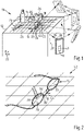
- the 1 shows as a scene 10 a table 12 with a tablecloth 14, on which a pair of glasses 16 with a frame 18 and with a left and right lens 20, 22 accommodated therein, in addition to further objects 24 in the form of a knife, a bottle, a cup and a Book and a cigar is arranged.
- the one in the 1 Scene 10 shown is time-invariant and contains characteristic points of a pattern of tablecloth 14 and objects 24 as structure points 26, which define a coordinate system 25 of scene 10, as well as characteristic points of spectacle frame 18 of spectacles 16.
- the scene 10 is recorded by the camera 28 in an image acquisition device 30 designed as a smartphone in a large number of different recording positions 32, 34, 36, ... by a user holding the smartphone switched to video mode with one hand and moving it along a trajectory 38 .
- the user thus captures the scene 10 using the camera 28 of the image capturing device 30 from different perspectives.
- Image capture device 30 contains a computer unit 40 for processing the recordings of scene 10 captured by camera 28.
- the 2 is a section 42 of a first image of the scene 10 with images 26 ′ of structure points 26 captured by the image capturing device 30 from a first recording position 32
- 3 is another detail 42 of a means of the image acquisition device 30 from one of the first recording position 32 different further recording position 36 captured first image of the scene 10 with images 26 'of structure points 26 shown.
- a multiplicity of structure points 26 are each detected with an imaging beam path which passes through the first and/or the second spectacle lens 20, 22 in the spectacle frame 18 of the spectacles 16 or not.
- images of the scene 10 are captured, which contain a section of the spectacle frame 18 that defines a coordinate system 44 of the spectacle frame 18.
- the 4 shows the coordinate system 25 of the scene 10 and a coordinate system 46 of the image capture device 30 with a spectacle lens 20, 22.
- the computer unit 40 in the image capture device 30 calculates the coordinates of the structure points 26 of a pattern 27 using a SLAM algorithm in the scene by means of a ray model in a coordinate system 46 referenced to the image capturing device 30, which in turn is referenced to the coordinate system 25 of the scene 10 and the coordinate system 44 of the spectacle frame 18 of the spectacles 16.
- a principal ray 53 , 53 ′ which passes through a spectacle lens 20 , 22 of the spectacles 16 , is then calculated from each imaged structure point 26 in accordance with the position of the image acquisition device 30 . From this and from the 3D coordinate of the point, a ray model then results, which reflects different viewing conditions of the same pair of glasses 16 in the same scene 10 and the imaging rays that are deflected and the different Layers and positions of an image acquisition device correspond, describes.
- An inverse approach is a reversal of the so-called forward calculation, in which the course of light rays through an optical system consisting of known optical interfaces and known refractive indices between the interfaces is calculated in an optical ray tracing, also known as ray tracing. Provided that the interfaces, their normals and the refractive indices are known, it is then possible to calculate each light ray through the system unambiguously.
- an optical interface or a refractive index is sought that matches a given number of light rays.
- the forward calculation is carried out using the area determined using the inverse approach, and a comparison of beam points in front of and/or behind the respective interface is then made.
- the so-called intrinsic camera calibration operator is used for the conversion of pixel coordinates C of the camera 28 in the image acquisition device 30 to the ray vector of an imaging beam path K .
- the camera calibration operator K can e.g. B. from a recording of a special calibration pattern, z. B. a checkerboard pattern or a dot pattern can be determined by means of the image acquisition device.
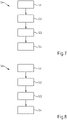
- the 7 is a flowchart 54 of the above-described method for measuring a left and/or right spectacle lens 20, 22 in spectacles 16.
- a first step S1 at least a first image of a scene 10 with a large number of structure points 26 and with a left and/or a right spectacle lens 20, 22 in a pair of spectacles 16 and with a section defining a coordinate system 44 of the spectacle frame 18 of the spectacle 16 is created of the spectacle frame 18 of the spectacles 16 is detected by means of an image acquisition device 30 with an imaging beam path for structure points 26 which passes through the first and/or the second spectacle lens 20, 22 of the spectacles 16.
- step S4 the refractive power distribution k(x, y) is then determined for at least one section of the left spectacle lens 20 in the coordinate system 44 of the spectacle frame 18 referenced to the coordinate system 25 of the scene 10 and/or the refractive power distribution is determined k(x, y) for at least one section of the right spectacle lens 22 in a coordinate system 25 of the scene 10 referenced to the coordinate system 44 of the spectacle frame 18 from the coordinates of the stationary, time-invariant structure points 26 and the image of the structure points 26 in the at least one first image of scene 10.
- the 8 shows a flowchart 54 for an alternative method to the above-described method for measuring a left and/or right spectacle lens 20, 22 in a pair of spectacles 16, which is described below with reference to FIG Figures 9 to 12 is described.
- a sequence of first images of a time-invariant scene 10 with a multiplicity of structure points 26 and with a left and/or a right spectacle lens 20, 22 in a spectacle 16 together with a section of the spectacle frame 18, which is a in the 4 shown coordinate system 44 of the spectacle frame 18 is defined.
- images of scene 10 are captured using imaging beam paths for structure points 26, which at least partially penetrate the first and/or the second spectacle lens 20, 22 of the spectacle 16 and on the first and/or the second spectacle lens 20, 22 the glasses 16 are at least partially passed.
- step S1 following step S2, as in FIG 10 to see a sequence of further images of the scene 10 with stationary, time-invariant structure points 26, but recorded without the glasses 16.
- step S2 can also precede step S1 or take place simultaneously with it.
- a step S3 the coordinate system 25 of the scene 10 is referenced to the coordinate system 44 of the spectacle frame 18 and then the coordinates of the structure points 26 in the coordinate system 25 of the scene 10 referenced to the coordinate system 46 of the image acquisition device 30 in the different recording positions from the at least another image of the scene 10 is calculated by means of image analysis.
- the refractive power distribution k(x,y) is determined for at least one section of the left spectacle lens 20 in the coordinate system 44 of the spectacle frame 18 referenced to the coordinate system 25 of the scene 10 and/or the refractive power distribution k(x,y ) for at least one section of the right spectacle lens 22 in the coordinate system 44 of the spectacle frame 18 from the coordinates of the structural points 26 and the image of the structural points 26 in the at least one first image of the scene 10.
- the computer unit of the image acquisition device 30 contains a program routine here, by means of which the position of the structural points 26 can be determined by evaluating neighboring relationships, in particular distances between the structural points 26 in the scene 10, in a coordinate system 44 coordinate system 25 of scene 10 referenced by eyeglass frame 18 is calculated.
- the invention relates to a method for measuring the local refractive power or the refractive power distribution of a left and/or a right spectacle lens 20, 22 in a spectacle frame 18. At least a first image of a scene 10 with at least one structural point 26 and with a left and/or a right spectacle lens 20, 22 in a spectacle frame 18 by means of an image acquisition device 30 from at least a first recording position 32 with at least one imaging beam path for structural points 26, which captures the first and/or the second spectacle lens 20, 22 in the spectacle frame 18 interspersed.
- At least two further images of scene 10 without the first and/or second spectacle lens 20, 22 of spectacle frame 18 or without the spectacle frame containing the left and/or right spectacle lens with the structure points 26 shown in the first image are captured by means of image capture device 30 from at least two different recording positions 32, 34, 36, one of which can be identical to the first recording position, and the coordinates of structure points 26 in a coordinate system 25 are calculated from the at least two other images of scene 10 by means of image evaluation, or it at least two further images of the scene 10 with the left and/or the right spectacle lens 20, 22 are created by means of an image acquisition device 30 from at least two further image positions different from the first image position with at least one imaging beam path for the structure points 26 e r detects the first and / or the second lens 20, 22 of the spectacle frame 18 does not penetrate, to then a refractive power distribution k (x, y) for at least a portion of the left lens 20 in a coordinate system 25 of the scene 10 referenced to the coordinate system 44 of the spectacle frame 18 and/or a ref
Landscapes
- Physics & Mathematics (AREA)
- General Physics & Mathematics (AREA)
- Engineering & Computer Science (AREA)
- Health & Medical Sciences (AREA)
- Ophthalmology & Optometry (AREA)
- Optics & Photonics (AREA)
- Analytical Chemistry (AREA)
- Chemical & Material Sciences (AREA)
- Theoretical Computer Science (AREA)
- Computer Vision & Pattern Recognition (AREA)
- Geometry (AREA)
- General Health & Medical Sciences (AREA)
- Eyeglasses (AREA)
- Testing Of Optical Devices Or Fibers (AREA)
- Investigating Or Analysing Materials By Optical Means (AREA)
- Eye Examination Apparatus (AREA)
Applications Claiming Priority (3)
| Application Number | Priority Date | Filing Date | Title |
|---|---|---|---|
| EP19170715.7A EP3730919A1 (fr) | 2019-04-23 | 2019-04-23 | Procédé et dispositif de mesure de la force de rupture locale ou de la distribution de la force de rupture d'un verre de lunettes |
| PCT/EP2020/061238 WO2020216799A1 (fr) | 2019-04-23 | 2020-04-22 | Procédé et dispositif pour mesurer la puissance optique locale et/ou la répartition de puissance optique d'un verre de lunettes |
| EP20723300.8A EP3959497B1 (fr) | 2019-04-23 | 2020-04-22 | Procédé et dispositif de mesure de la force de rupture locale ou de la distribution de la force de rupture d'un verre de lunettes |
Related Parent Applications (2)
| Application Number | Title | Priority Date | Filing Date |
|---|---|---|---|
| EP20723300.8A Division EP3959497B1 (fr) | 2019-04-23 | 2020-04-22 | Procédé et dispositif de mesure de la force de rupture locale ou de la distribution de la force de rupture d'un verre de lunettes |
| EP20723300.8A Division-Into EP3959497B1 (fr) | 2019-04-23 | 2020-04-22 | Procédé et dispositif de mesure de la force de rupture locale ou de la distribution de la force de rupture d'un verre de lunettes |
Publications (3)
| Publication Number | Publication Date |
|---|---|
| EP3982102A1 true EP3982102A1 (fr) | 2022-04-13 |
| EP3982102B1 EP3982102B1 (fr) | 2024-10-16 |
| EP3982102C0 EP3982102C0 (fr) | 2024-10-16 |
Family
ID=66251606
Family Applications (3)
| Application Number | Title | Priority Date | Filing Date |
|---|---|---|---|
| EP19170715.7A Withdrawn EP3730919A1 (fr) | 2019-04-23 | 2019-04-23 | Procédé et dispositif de mesure de la force de rupture locale ou de la distribution de la force de rupture d'un verre de lunettes |
| EP20723300.8A Active EP3959497B1 (fr) | 2019-04-23 | 2020-04-22 | Procédé et dispositif de mesure de la force de rupture locale ou de la distribution de la force de rupture d'un verre de lunettes |
| EP21209645.7A Active EP3982102B1 (fr) | 2019-04-23 | 2020-04-22 | Procédé et dispositif pour mesurer la puissance optique locale et/ou la répartition de puissance optique d'un verre de lunettes |
Family Applications Before (2)
| Application Number | Title | Priority Date | Filing Date |
|---|---|---|---|
| EP19170715.7A Withdrawn EP3730919A1 (fr) | 2019-04-23 | 2019-04-23 | Procédé et dispositif de mesure de la force de rupture locale ou de la distribution de la force de rupture d'un verre de lunettes |
| EP20723300.8A Active EP3959497B1 (fr) | 2019-04-23 | 2020-04-22 | Procédé et dispositif de mesure de la force de rupture locale ou de la distribution de la force de rupture d'un verre de lunettes |
Country Status (8)
| Country | Link |
|---|---|
| US (1) | US11982878B2 (fr) |
| EP (3) | EP3730919A1 (fr) |
| JP (1) | JP7126031B2 (fr) |
| KR (1) | KR102444768B1 (fr) |
| CN (1) | CN113711003B (fr) |
| ES (1) | ES2933452T3 (fr) |
| IL (1) | IL287469B2 (fr) |
| WO (1) | WO2020216799A1 (fr) |
Families Citing this family (7)
| Publication number | Priority date | Publication date | Assignee | Title |
|---|---|---|---|---|
| EP3730918A1 (fr) | 2019-04-23 | 2020-10-28 | Carl Zeiss Vision International GmbH | Procédé et dispositif de mesure de la force de rupture locale et / ou de la répartition de la force de rupture d'un verre de lunettes |
| EP3730037A1 (fr) | 2019-04-23 | 2020-10-28 | Carl Zeiss Vision International GmbH | Détermination d'une erreur de réfection d'un il |
| EP3730998A1 (fr) | 2019-04-23 | 2020-10-28 | Carl Zeiss Vision International GmbH | Détermination d'au moins un paramètre optique d'un verre de lunettes |
| US12247826B2 (en) * | 2021-06-11 | 2025-03-11 | Optinno BV | Spectacle lens shape measurement method |
| CN114112328A (zh) * | 2021-12-13 | 2022-03-01 | 上海理工大学 | 一种镜片屈光度测量装置及方法 |
| EP4361704A1 (fr) * | 2022-10-27 | 2024-05-01 | Pupil Labs GmbH | Module de suivi oculaire et dispositif pouvant être porté sur la tête |
| EP4443219A1 (fr) * | 2023-04-03 | 2024-10-09 | Carl Zeiss Vision International GmbH | Appareil et procédé adaptés pour balayer une monture de lunettes |
Citations (7)
| Publication number | Priority date | Publication date | Assignee | Title |
|---|---|---|---|---|
| EP2608109A1 (fr) | 2011-12-19 | 2013-06-26 | Thomson Licensing | Procédé et dispositif d'estimation de la puissance optique de verres de correction dans une paire de lunettes portée par un spectateur |
| US20150029323A1 (en) | 2013-07-24 | 2015-01-29 | Fujitsu Limited | Image processing device, electronic apparatus, and glasses characteristic determination method |
| US20150362998A1 (en) | 2014-06-17 | 2015-12-17 | Amazon Technologies, Inc. | Motion control for managing content |
| WO2016076530A1 (fr) | 2014-11-13 | 2016-05-19 | 윤철주 | Système de mesure de puissance de verre de lunettes utilisant un dispositif mobile, procédé et programme associés |
| WO2016207412A1 (fr) | 2015-06-25 | 2016-12-29 | Carl Zeiss Ag | Mesure des données individuelles d'une paire de lunettes |
| WO2017134275A1 (fr) | 2016-02-05 | 2017-08-10 | Eidgenossische Technische Hochschule Zurich | Procédés et systèmes permettant de déterminer un axe optique et/ou des propriétés physiques d'une lentille, et leur utilisation dans l'imagerie virtuelle et des visiocasques |
| US10019140B1 (en) | 2014-06-26 | 2018-07-10 | Amazon Technologies, Inc. | One-handed zoom |
Family Cites Families (11)
| Publication number | Priority date | Publication date | Assignee | Title |
|---|---|---|---|---|
| US3880525A (en) * | 1974-05-08 | 1975-04-29 | American Optical Corp | Method and apparatus for determining the refractive characteristics of a lens |
| JPS5690233A (en) * | 1979-12-24 | 1981-07-22 | Asahi Optical Co Ltd | Automatic lens meter |
| JP4086429B2 (ja) * | 1998-10-12 | 2008-05-14 | Hoya株式会社 | 眼鏡レンズの評価方法及び評価装置 |
| KR20010061557A (ko) * | 1999-12-28 | 2001-07-07 | 박종섭 | 반도체 메모리 소자 및 그 제조 방법 |
| KR20060093596A (ko) * | 2005-02-22 | 2006-08-25 | 엘지전자 주식회사 | 이동단말기의 디옵터 측정 방법 |
| EP2189777B1 (fr) * | 2007-08-31 | 2020-01-01 | Hoya Corporation | Procédé et dispositif pour évaluer une lentille à puissance de réfraction progressive et procédé pour fabriquer une lentille à puissance de réfraction progressive |
| DE102014116665B4 (de) * | 2014-09-22 | 2024-07-25 | Carl Zeiss Ag | Verfahren und Vorrichtungen zur Bestimmung der Augenrefraktion |
| CN204514573U (zh) * | 2015-01-15 | 2015-07-29 | 中山大学中山眼科中心 | 一种镜片周边有效屈光力的测量装置 |
| EP3730037A1 (fr) | 2019-04-23 | 2020-10-28 | Carl Zeiss Vision International GmbH | Détermination d'une erreur de réfection d'un il |
| EP3730918A1 (fr) | 2019-04-23 | 2020-10-28 | Carl Zeiss Vision International GmbH | Procédé et dispositif de mesure de la force de rupture locale et / ou de la répartition de la force de rupture d'un verre de lunettes |
| EP3730036A1 (fr) | 2019-04-23 | 2020-10-28 | Carl Zeiss Vision International GmbH | Détermination d'une erreur de réfection d'un il |
-
2019
- 2019-04-23 EP EP19170715.7A patent/EP3730919A1/fr not_active Withdrawn
-
2020
- 2020-04-22 IL IL287469A patent/IL287469B2/en unknown
- 2020-04-22 EP EP20723300.8A patent/EP3959497B1/fr active Active
- 2020-04-22 KR KR1020217037544A patent/KR102444768B1/ko active Active
- 2020-04-22 JP JP2021563134A patent/JP7126031B2/ja active Active
- 2020-04-22 ES ES20723300T patent/ES2933452T3/es active Active
- 2020-04-22 EP EP21209645.7A patent/EP3982102B1/fr active Active
- 2020-04-22 CN CN202080030607.8A patent/CN113711003B/zh active Active
- 2020-04-22 WO PCT/EP2020/061238 patent/WO2020216799A1/fr not_active Ceased
-
2021
- 2021-10-19 US US17/504,905 patent/US11982878B2/en active Active
Patent Citations (7)
| Publication number | Priority date | Publication date | Assignee | Title |
|---|---|---|---|---|
| EP2608109A1 (fr) | 2011-12-19 | 2013-06-26 | Thomson Licensing | Procédé et dispositif d'estimation de la puissance optique de verres de correction dans une paire de lunettes portée par un spectateur |
| US20150029323A1 (en) | 2013-07-24 | 2015-01-29 | Fujitsu Limited | Image processing device, electronic apparatus, and glasses characteristic determination method |
| US20150362998A1 (en) | 2014-06-17 | 2015-12-17 | Amazon Technologies, Inc. | Motion control for managing content |
| US10019140B1 (en) | 2014-06-26 | 2018-07-10 | Amazon Technologies, Inc. | One-handed zoom |
| WO2016076530A1 (fr) | 2014-11-13 | 2016-05-19 | 윤철주 | Système de mesure de puissance de verre de lunettes utilisant un dispositif mobile, procédé et programme associés |
| WO2016207412A1 (fr) | 2015-06-25 | 2016-12-29 | Carl Zeiss Ag | Mesure des données individuelles d'une paire de lunettes |
| WO2017134275A1 (fr) | 2016-02-05 | 2017-08-10 | Eidgenossische Technische Hochschule Zurich | Procédés et systèmes permettant de déterminer un axe optique et/ou des propriétés physiques d'une lentille, et leur utilisation dans l'imagerie virtuelle et des visiocasques |
Non-Patent Citations (6)
| Title |
|---|
| A. TEICHMANN ET AL., UNSUPERVISED INTRINSIC CALIBRATION OF DEPTH SENSORS VIA SLAM, ROBOTICS: SCIENCE AND SYSTEMS 2013, BERLIN GERMANY, 24 June 2013 (2013-06-24) |
| CHARI VISESH ET AL: "A Theory of Refractive Photo-Light-Path Triangulation", 2017 IEEE CONFERENCE ON COMPUTER VISION AND PATTERN RECOGNITION (CVPR), IEEE COMPUTER SOCIETY, US, 23 June 2013 (2013-06-23), pages 1438 - 1445, XP032492941, ISSN: 1063-6919, [retrieved on 20131002], DOI: 10.1109/CVPR.2013.189 * |
| HAN KAI ET AL: "Dense Reconstruction of Transparent Objects by Altering Incident Light Paths Through Refraction", INTERNATIONAL JOURNAL OF COMPUTER VISION, KLUWER ACADEMIC PUBLISHERS, NORWELL, US, vol. 126, no. 5, 30 September 2017 (2017-09-30), pages 460 - 475, XP036454203, ISSN: 0920-5691, [retrieved on 20170930], DOI: 10.1007/S11263-017-1045-3 * |
| K.N. KUTUKALOSE. STEGER: "A Theory of Refractive and specular 3D Shape by Light-Path Triangulation", INTERNATIONAL JOURNALS OF COMPUTER VISION, vol. 76, no. 1, 2008, pages 13 - 29 |
| KIRIAKOS N KUTULAKOS ET AL: "A Theory of Refractive and Specular 3D Shape by Light-Path Triangulation", INTERNATIONAL JOURNAL OF COMPUTER VISION, KLUWER ACADEMIC PUBLISHERS, BO, vol. 76, no. 1, 11 July 2007 (2007-07-11), pages 13 - 29, XP019557768, ISSN: 1573-1405, DOI: 10.1007/S11263-007-0049-9 * |
| VON R. HARTLEYA. ZISSERMAN: "Multiple View Geometry", 2004, CAMBRIDGE UNIVERSITY PRESS, pages: 153 - 193 |
Also Published As
| Publication number | Publication date |
|---|---|
| JP7126031B2 (ja) | 2022-08-25 |
| KR102444768B1 (ko) | 2022-09-19 |
| JP2022528575A (ja) | 2022-06-14 |
| EP3982102B1 (fr) | 2024-10-16 |
| US20220035183A1 (en) | 2022-02-03 |
| BR112021021170A2 (pt) | 2021-12-14 |
| IL287469B1 (en) | 2023-06-01 |
| IL287469A (en) | 2021-12-01 |
| EP3959497A1 (fr) | 2022-03-02 |
| CN113711003A (zh) | 2021-11-26 |
| US11982878B2 (en) | 2024-05-14 |
| EP3959497B1 (fr) | 2022-11-09 |
| CN113711003B (zh) | 2024-03-08 |
| EP3730919A1 (fr) | 2020-10-28 |
| ES2933452T3 (es) | 2023-02-09 |
| EP3982102C0 (fr) | 2024-10-16 |
| WO2020216799A1 (fr) | 2020-10-29 |
| IL287469B2 (en) | 2023-10-01 |
| KR20210147075A (ko) | 2021-12-06 |
Similar Documents
| Publication | Publication Date | Title |
|---|---|---|
| EP3959497B1 (fr) | Procédé et dispositif de mesure de la force de rupture locale ou de la distribution de la force de rupture d'un verre de lunettes | |
| EP3924710B1 (fr) | Procédé et dispositif de mesure de la force de rupture locale et / ou de la répartition de la force de rupture d'un verre de lunettes | |
| EP3542211B2 (fr) | Procédé et dispositif ainsi que programme informatique destinés à déterminer une représentation d'un bord de verre de lunettes | |
| EP3956721B1 (fr) | Détermination d'au moins un paramètre optique d'un verre de lunettes | |
| DE102016106121B4 (de) | Verfahren und Vorrichtung zum Bestimmen von Parametern zur Brillenanpassung | |
| EP3657236B1 (fr) | Procédé, dispositif et programme informatique destinés à l'adaptation virtuelle d'une monture de lunettes | |
| EP3702832B1 (fr) | Procédé, dispositifs et programme informatique de détermination d'un point visuel proche | |
| EP3183616B1 (fr) | Détermination de données d'utilisateur avec prise en compte de données d'image d'une monture de lunettes choisie | |
| DE60117432T2 (de) | Verfahren und Gerät zur Simulation eines optischen Okularsystems | |
| EP3869150B1 (fr) | Méthode et appareil pour mesurer la cornée d'un sujet | |
| EP3103060A1 (fr) | Analyseur d'image 2d | |
| WO2009062945A1 (fr) | Procédé et dispositif pour détecter et suivre une paire d'yeux | |
| EP3210071B1 (fr) | Dispositif et procédé de détermination de paramètres optiques | |
| EP4143628B1 (fr) | Procédé mis en oeuvre par ordinateur de détermination des paramètres de centrage pour terminaux mobiles, terminal mobile et programme informatique | |
| EP3730036A1 (fr) | Détermination d'une erreur de réfection d'un il | |
| EP3574370B1 (fr) | Procédé assisté par ordinateur destiné à déterminer une représentation d'un bord de monture de lunette ou d'une représentation des bords de verres de lunettes | |
| DE102019001762A1 (de) | Verfahren, Zentriervorrichtung und Computerprogrammprodukt zur Abstandsmessung eines Benutzers von einer Zentriervorrichtung | |
| EP4256307A1 (fr) | Procédé mis en oeuvre par ordinateur, programme informatique, système de traitement de données et dispositif de détermination du comportement de réflectance de la surface d'un objet, et support de stockage contenant des instructions pour la détermination du comportement de réflectance de la surface d'un objet |
Legal Events
| Date | Code | Title | Description |
|---|---|---|---|
| PUAI | Public reference made under article 153(3) epc to a published international application that has entered the european phase |
Free format text: ORIGINAL CODE: 0009012 |
|
| STAA | Information on the status of an ep patent application or granted ep patent |
Free format text: STATUS: THE APPLICATION HAS BEEN PUBLISHED |
|
| AC | Divisional application: reference to earlier application |
Ref document number: 3959497 Country of ref document: EP Kind code of ref document: P |
|
| AK | Designated contracting states |
Kind code of ref document: A1 Designated state(s): AL AT BE BG CH CY CZ DE DK EE ES FI FR GB GR HR HU IE IS IT LI LT LU LV MC MK MT NL NO PL PT RO RS SE SI SK SM TR |
|
| STAA | Information on the status of an ep patent application or granted ep patent |
Free format text: STATUS: REQUEST FOR EXAMINATION WAS MADE |
|
| 17P | Request for examination filed |
Effective date: 20220812 |
|
| RBV | Designated contracting states (corrected) |
Designated state(s): AL AT BE BG CH CY CZ DE DK EE ES FI FR GB GR HR HU IE IS IT LI LT LU LV MC MK MT NL NO PL PT RO RS SE SI SK SM TR |
|
| GRAP | Despatch of communication of intention to grant a patent |
Free format text: ORIGINAL CODE: EPIDOSNIGR1 |
|
| STAA | Information on the status of an ep patent application or granted ep patent |
Free format text: STATUS: GRANT OF PATENT IS INTENDED |
|
| RIC1 | Information provided on ipc code assigned before grant |
Ipc: G02C 7/06 20060101ALN20240425BHEP Ipc: G02C 13/00 20060101ALI20240425BHEP Ipc: G01M 11/02 20060101AFI20240425BHEP |
|
| RIC1 | Information provided on ipc code assigned before grant |
Ipc: G02C 7/06 20060101ALN20240502BHEP Ipc: G02C 13/00 20060101ALI20240502BHEP Ipc: G01M 11/02 20060101AFI20240502BHEP |
|
| INTG | Intention to grant announced |
Effective date: 20240521 |
|
| GRAS | Grant fee paid |
Free format text: ORIGINAL CODE: EPIDOSNIGR3 |
|
| GRAA | (expected) grant |
Free format text: ORIGINAL CODE: 0009210 |
|
| STAA | Information on the status of an ep patent application or granted ep patent |
Free format text: STATUS: THE PATENT HAS BEEN GRANTED |
|
| AC | Divisional application: reference to earlier application |
Ref document number: 3959497 Country of ref document: EP Kind code of ref document: P |
|
| AK | Designated contracting states |
Kind code of ref document: B1 Designated state(s): AL AT BE BG CH CY CZ DE DK EE ES FI FR GB GR HR HU IE IS IT LI LT LU LV MC MK MT NL NO PL PT RO RS SE SI SK SM TR |
|
| REG | Reference to a national code |
Ref country code: GB Ref legal event code: FG4D Free format text: NOT ENGLISH |
|
| REG | Reference to a national code |
Ref country code: CH Ref legal event code: EP |
|
| REG | Reference to a national code |
Ref country code: IE Ref legal event code: FG4D Free format text: LANGUAGE OF EP DOCUMENT: GERMAN |
|
| REG | Reference to a national code |
Ref country code: DE Ref legal event code: R096 Ref document number: 502020009532 Country of ref document: DE |
|
| U01 | Request for unitary effect filed |
Effective date: 20241025 |
|
| U07 | Unitary effect registered |
Designated state(s): AT BE BG DE DK EE FI FR IT LT LU LV MT NL PT RO SE SI Effective date: 20241107 |
|
| PG25 | Lapsed in a contracting state [announced via postgrant information from national office to epo] |
Ref country code: IS Free format text: LAPSE BECAUSE OF FAILURE TO SUBMIT A TRANSLATION OF THE DESCRIPTION OR TO PAY THE FEE WITHIN THE PRESCRIBED TIME-LIMIT Effective date: 20250216 Ref country code: HR Free format text: LAPSE BECAUSE OF FAILURE TO SUBMIT A TRANSLATION OF THE DESCRIPTION OR TO PAY THE FEE WITHIN THE PRESCRIBED TIME-LIMIT Effective date: 20241016 |
|
| PG25 | Lapsed in a contracting state [announced via postgrant information from national office to epo] |
Ref country code: ES Free format text: LAPSE BECAUSE OF FAILURE TO SUBMIT A TRANSLATION OF THE DESCRIPTION OR TO PAY THE FEE WITHIN THE PRESCRIBED TIME-LIMIT Effective date: 20241016 |
|
| PG25 | Lapsed in a contracting state [announced via postgrant information from national office to epo] |
Ref country code: NO Free format text: LAPSE BECAUSE OF FAILURE TO SUBMIT A TRANSLATION OF THE DESCRIPTION OR TO PAY THE FEE WITHIN THE PRESCRIBED TIME-LIMIT Effective date: 20250116 |
|
| PG25 | Lapsed in a contracting state [announced via postgrant information from national office to epo] |
Ref country code: GR Free format text: LAPSE BECAUSE OF FAILURE TO SUBMIT A TRANSLATION OF THE DESCRIPTION OR TO PAY THE FEE WITHIN THE PRESCRIBED TIME-LIMIT Effective date: 20250117 |
|
| PG25 | Lapsed in a contracting state [announced via postgrant information from national office to epo] |
Ref country code: PL Free format text: LAPSE BECAUSE OF FAILURE TO SUBMIT A TRANSLATION OF THE DESCRIPTION OR TO PAY THE FEE WITHIN THE PRESCRIBED TIME-LIMIT Effective date: 20241016 |
|
| PG25 | Lapsed in a contracting state [announced via postgrant information from national office to epo] |
Ref country code: RS Free format text: LAPSE BECAUSE OF FAILURE TO SUBMIT A TRANSLATION OF THE DESCRIPTION OR TO PAY THE FEE WITHIN THE PRESCRIBED TIME-LIMIT Effective date: 20250116 |
|
| U20 | Renewal fee for the european patent with unitary effect paid |
Year of fee payment: 6 Effective date: 20250425 |
|
| PG25 | Lapsed in a contracting state [announced via postgrant information from national office to epo] |
Ref country code: SM Free format text: LAPSE BECAUSE OF FAILURE TO SUBMIT A TRANSLATION OF THE DESCRIPTION OR TO PAY THE FEE WITHIN THE PRESCRIBED TIME-LIMIT Effective date: 20241016 |
|
| PG25 | Lapsed in a contracting state [announced via postgrant information from national office to epo] |
Ref country code: SK Free format text: LAPSE BECAUSE OF FAILURE TO SUBMIT A TRANSLATION OF THE DESCRIPTION OR TO PAY THE FEE WITHIN THE PRESCRIBED TIME-LIMIT Effective date: 20241016 |
|
| PG25 | Lapsed in a contracting state [announced via postgrant information from national office to epo] |
Ref country code: CZ Free format text: LAPSE BECAUSE OF FAILURE TO SUBMIT A TRANSLATION OF THE DESCRIPTION OR TO PAY THE FEE WITHIN THE PRESCRIBED TIME-LIMIT Effective date: 20241016 |
|
| PLBE | No opposition filed within time limit |
Free format text: ORIGINAL CODE: 0009261 |
|
| STAA | Information on the status of an ep patent application or granted ep patent |
Free format text: STATUS: NO OPPOSITION FILED WITHIN TIME LIMIT |
|
| 26N | No opposition filed |
Effective date: 20250717 |
|
| REG | Reference to a national code |
Ref country code: CH Ref legal event code: H13 Free format text: ST27 STATUS EVENT CODE: U-0-0-H10-H13 (AS PROVIDED BY THE NATIONAL OFFICE) Effective date: 20251125 |
|
| PG25 | Lapsed in a contracting state [announced via postgrant information from national office to epo] |
Ref country code: MC Free format text: LAPSE BECAUSE OF FAILURE TO SUBMIT A TRANSLATION OF THE DESCRIPTION OR TO PAY THE FEE WITHIN THE PRESCRIBED TIME-LIMIT Effective date: 20241016 |
|
| GBPC | Gb: european patent ceased through non-payment of renewal fee |
Effective date: 20250422 |
|
| PG25 | Lapsed in a contracting state [announced via postgrant information from national office to epo] |
Ref country code: GB Free format text: LAPSE BECAUSE OF NON-PAYMENT OF DUE FEES Effective date: 20250422 |
|
| PG25 | Lapsed in a contracting state [announced via postgrant information from national office to epo] |
Ref country code: CH Free format text: LAPSE BECAUSE OF NON-PAYMENT OF DUE FEES Effective date: 20250430 |
|
| PG25 | Lapsed in a contracting state [announced via postgrant information from national office to epo] |
Ref country code: IE Free format text: LAPSE BECAUSE OF NON-PAYMENT OF DUE FEES Effective date: 20250422 |