EP3984565A1 - Dispositif de chauffage ambiant, ainsi qu'agencement d'un dispositif de chauffage ambiant - Google Patents
Dispositif de chauffage ambiant, ainsi qu'agencement d'un dispositif de chauffage ambiant Download PDFInfo
- Publication number
- EP3984565A1 EP3984565A1 EP21201881.6A EP21201881A EP3984565A1 EP 3984565 A1 EP3984565 A1 EP 3984565A1 EP 21201881 A EP21201881 A EP 21201881A EP 3984565 A1 EP3984565 A1 EP 3984565A1
- Authority
- EP
- European Patent Office
- Prior art keywords
- heating device
- room air
- air heating
- combustion chamber
- room
- Prior art date
- Legal status (The legal status is an assumption and is not a legal conclusion. Google has not performed a legal analysis and makes no representation as to the accuracy of the status listed.)
- Withdrawn
Links
- 238000010438 heat treatment Methods 0.000 title claims abstract description 110
- 239000012530 fluid Substances 0.000 claims abstract description 50
- 238000002485 combustion reaction Methods 0.000 claims description 69
- 239000002028 Biomass Substances 0.000 claims description 8
- 239000004449 solid propellant Substances 0.000 claims description 2
- 239000003570 air Substances 0.000 description 144
- 239000007789 gas Substances 0.000 description 9
- 238000011179 visual inspection Methods 0.000 description 4
- 239000002023 wood Substances 0.000 description 4
- 241000700605 Viruses Species 0.000 description 3
- 230000001580 bacterial effect Effects 0.000 description 3
- 239000008188 pellet Substances 0.000 description 3
- 239000007787 solid Substances 0.000 description 3
- 230000001954 sterilising effect Effects 0.000 description 3
- 238000004659 sterilization and disinfection Methods 0.000 description 3
- 238000009423 ventilation Methods 0.000 description 3
- 241001465754 Metazoa Species 0.000 description 2
- 239000012080 ambient air Substances 0.000 description 2
- 238000005253 cladding Methods 0.000 description 2
- 239000000645 desinfectant Substances 0.000 description 2
- 239000000446 fuel Substances 0.000 description 2
- 241000894006 Bacteria Species 0.000 description 1
- 230000001133 acceleration Effects 0.000 description 1
- QVGXLLKOCUKJST-UHFFFAOYSA-N atomic oxygen Chemical compound [O] QVGXLLKOCUKJST-UHFFFAOYSA-N 0.000 description 1
- 238000004140 cleaning Methods 0.000 description 1
- 239000003245 coal Substances 0.000 description 1
- 230000000694 effects Effects 0.000 description 1
- 238000003912 environmental pollution Methods 0.000 description 1
- 230000005484 gravity Effects 0.000 description 1
- 231100000206 health hazard Toxicity 0.000 description 1
- 238000007689 inspection Methods 0.000 description 1
- 238000009413 insulation Methods 0.000 description 1
- 239000000463 material Substances 0.000 description 1
- 239000002184 metal Substances 0.000 description 1
- 239000001301 oxygen Substances 0.000 description 1
- 229910052760 oxygen Inorganic materials 0.000 description 1
- 230000005855 radiation Effects 0.000 description 1
- 239000002994 raw material Substances 0.000 description 1
- 230000002787 reinforcement Effects 0.000 description 1
- 239000007921 spray Substances 0.000 description 1
- 230000003612 virological effect Effects 0.000 description 1
Images

Classifications
-
- A—HUMAN NECESSITIES
- A61—MEDICAL OR VETERINARY SCIENCE; HYGIENE
- A61L—METHODS OR APPARATUS FOR STERILISING MATERIALS OR OBJECTS IN GENERAL; DISINFECTION, STERILISATION OR DEODORISATION OF AIR; CHEMICAL ASPECTS OF BANDAGES, DRESSINGS, ABSORBENT PADS OR SURGICAL ARTICLES; MATERIALS FOR BANDAGES, DRESSINGS, ABSORBENT PADS OR SURGICAL ARTICLES
- A61L9/00—Disinfection, sterilisation or deodorisation of air
- A61L9/16—Disinfection, sterilisation or deodorisation of air using physical phenomena
- A61L9/18—Radiation
- A61L9/20—Ultraviolet radiation
-
- F—MECHANICAL ENGINEERING; LIGHTING; HEATING; WEAPONS; BLASTING
- F24—HEATING; RANGES; VENTILATING
- F24B—DOMESTIC STOVES OR RANGES FOR SOLID FUELS; IMPLEMENTS FOR USE IN CONNECTION WITH STOVES OR RANGES
- F24B7/00—Stoves, ranges or flue-gas ducts, with additional provisions for convection heating
- F24B7/02—Stoves, ranges or flue-gas ducts, with additional provisions for convection heating with external air ducts
Definitions
- the invention relates to a room air heating device and an arrangement of a room air heating device.
- Room air heating devices are already known from the prior art. These serve, among other things, to heat a fluid, in particular air, located in a room.
- the problem with the room air heating devices known from the prior art is that the bacteria and virus load in the room is increased by the heating heat flow. This often leads to sick residents of the room to be heated.
- a room air heating device comprising an air duct arrangement and a sterilizer unit, the air duct arrangement having an inlet and an outlet, the air duct arrangement being designed to direct a fluid flow, in particular an air flow, from the inlet to the outlet, the air duct arrangement having at least one has a heatable and/or heated wall, the sterilizer unit being arranged in such a way that it sterilizes and/or can sterilize the fluid flow.
- the inventive room air heater is used in particular to a To heat room air, for example a room of a building.
- the room air heating device comprises at least one air duct arrangement, which in turn has an inlet and an outlet, it being possible for a fluid flow to be conducted from the inlet to the outlet through the air duct arrangement.
- the inlet therefore serves in particular as an entry and the outlet as an exit of a fluid flow from or from the environment into the air-guiding arrangement.
- the air duct arrangement advantageously extends at least partially through an area of the room air heating device.
- the air duct arrangement can also be arranged at an externally accessible point which, in particular together with an on-site wall, for example of the room to be heated, forms a duct in a final arrangement position or in a mounted state.
- the air routing arrangement can form a duct through the room air heating device and/or form a duct together with a wall on site.
- the air guiding arrangement serves in particular to guide a fluid flow from the inlet to the outlet of the air guiding arrangement.
- the air guiding arrangement can therefore serve to limit the direction or the flow path of the fluid flow and/or at least partially specify it and/or to guide the fluid flow between the inlet and the outlet.
- the fluid flow is in particular an air flow which is guided from the room to be heated into the inlet via the air duct arrangement to the outlet into the room or rooms to be heated.
- the air duct arrangement has a heatable wall. This wall can be heated or can be heated in particular by a heating device of the room air heating device.
- Such a heating device of the room air heating device can be and/or include, for example, a radiator, a combustion chamber, in particular a gas or solid combustion chamber, a combustion chamber for biomass or an electric heater.
- the heating device of the room air heating device expediently has a heating output of at least 800 watts, preferably at least 1200 watts and particularly preferably at least 2000 watts and most preferably at least 4000 watts.
- the heatable wall can be heated directly or indirectly by the heating device of the room air heating device. In other words, the heatable wall can therefore be designed in such a way that it can be heated by the heating device of the room air heating device.
- the room air heater also has a sterilizer unit which is arranged in such a way that it sterilizes and/or can sterilize the fluid flow.
- sterilization can be understood to mean that the bacterial load and/or the viral load of the fluid flow through the sterilizer unit is reduced.
- a sterilizer unit can be and/or include, for example, a UV lamp, a cleaning grid, in particular a very close-meshed one, a disinfectant spray unit and/or an additional heating device.
- Arranging the sterilizer unit in such a way that the heated or heatable fluid stream flowing from the inlet to the outlet is sterilized and/or can be sterilized by the sterilizer unit means that the virus and/or bacterial load can be reduced by the heating. Therefore, the room air heating device according to the invention can achieve a significant reduction in the risk to the health of people and animals in the room to be heated or in the heated room.
- the fluid stream is preferably driven and/or drivable, in particular exclusively, by convection.
- the room air heating device can be designed in such a way that the fluid flow to be heated, which can advantageously flow at least partially through the room air heating device, flows through it at least partially, preferably completely, by heating the fluid flow in the air duct arrangement from the inlet to the outlet.
- the room air heating device can therefore be designed in particular in such a way that the air flow or the fluid flow to be heated is driven, advantageously exclusively, by the heating of the heatable wall from the inlet to the outlet.
- the room air heating device or at least the air duct arrangement, in particular between the inlet and Outlet be designed without a fan.
- the inlet is arranged below the outlet.
- this can mean that the inlet and the outlet are arranged relative to each other such that in a mounted state or an arranged state in which the room air heating device is particularly able to heat the fluid flow between the inlet and the outlet , the inlet is spaced from the outlet in the direction opposite to the acceleration of gravity vector. Therefore, in particular, the maximum height of the inlet can be smaller than the minimum height of the outlet—in an assembled state.
- the room air heating device can have a conveying device, preferably within the air duct arrangement, with the fluid flow being conveyed or capable of being conveyed from the inlet to the outlet by the conveying device.
- the room air heating device can therefore have a device which (forcedly) promotes the fluid flow from the inlet to the outlet.
- the conveying device can therefore have a fan and/or blades.
- the use of a conveying device makes it possible in a particularly simple manner to establish a fluid flow from the inlet to the outlet.
- a combination of the (naturally) convectively driven fluid flow and the (forced) driving of the fluid flow by a conveyor means that the dimensions of the conveyor can be particularly small, so that the energy requirement and/or the noise pollution of the conveyor can be reduced.
- the room air heating device advantageously has a combustion chamber.
- the heating device of the room air heating device can have a space for burning materials.
- this is Combustion chamber a solid combustion chamber in order to be able to provide high energy outputs.
- the combustion chamber can therefore be designed in particular in such a way that it does not burn any gas or other volatile, in particular fluid, fuels.
- the combustion chamber can therefore represent a combustion chamber for burning coal or wood.
- the combustion chamber can represent a biomass utilization combustion chamber, so that, for example, wood pellets and/or logs can be burned in the combustion chamber. In this way, in particular, a CO2-favorable heatability can be achieved.
- the combustion chamber is a sealed chamber.
- the room air heating device is designed in such a way that it does not use and/or has no connection with the surrounding room air to provide oxygen for combustion in the combustion chamber.
- the combustion chamber can be a combustion chamber for biomass and/or solid fuels.
- the combustion chamber of the room air heating device in such a way that it can utilize solids, a particularly cost-effective and visually attractive combustion chamber can be achieved.
- the combustion chamber By designing the combustion chamber as a combustion chamber for biomass or a biomass utilization combustion chamber, the combustion chamber can be operated as a CO2-neutral combustion chamber and/or the CO2 that occurs The burden of using renewable raw materials can be reduced.
- the biomass can be firewood and/or wood pellets, for example.
- At least one of the heatable and/or the heated walls is advantageously formed, at least in part, by an exhaust gas line, in particular an exhaust gas line of the combustion chamber.
- at least one of the heatable walls of the air duct arrangement can be designed in such a way that it at least partially forms an exhaust gas flow, in particular from the combustion chamber of the heating device of the room air heating device.
- at least one of the heatable walls of the air duct arrangement can be designed in such a way that it at least partially surrounds an exhaust gas flow and/or an exhaust gas line, in particular from the combustion chamber of the room air heating device.
- the thermal energy contained in the exhaust gas can be used efficiently in an effective manner.
- at least one of the heatable and/or the heated walls can also be a wall of a fireplace, in particular a wall of a combustion chamber of such a fireplace.
- At least one, preferably all, of the heatable and/or the heated walls is or can be heated by the combustion chamber and/or by the heating device of the room air heating device.
- this can mean that the combustion chamber or the heating device of the room air heating device heats the heatable walls or the at least one heatable wall. Therefore, in particular, no further and/or external heating devices are provided which serve to heat the walls of the air duct arrangement.
- the term “heating device” within the meaning of the invention should not be understood as meaning smaller heat sources such as, for example, light bulbs or UV lamps. Smaller heat sources have in particular a heat output of less than 200 watts, preferably less than 100 watts, and particularly preferably less than 50 watts.
- At least one of the heatable and/or heated walls forms, at least in part, a cladding wall, in particular a cladding of the combustion chamber.
- the heatable wall itself can form part of the fireplace or the combustion chamber, in particular an outer wall of the combustion chamber, and/or cover the combustion chamber with respect to the air duct arrangement.
- the wall to be heated can be heated particularly effectively and directly by the combustion chamber, so that heat transfer can take place at high temperatures in a particularly energy-efficient manner.
- At least one of the heatable and/or heated walls is made of metal.
- a particularly effective heat conduction can be achieved in this way.
- At least one of the heatable and/or heated walls can be made of concrete. As a result, a particularly cost-effective heatable or heated wall can be achieved.
- the room air heating device has a viewing recess or a viewing window, with the viewing recess or the viewing window enabling a view into the combustion space of the combustion chamber or into the combustion chamber from the surroundings.
- the viewing recess and/or the viewing window advantageously has a viewing area of at least 300 cm 2 , preferably at least 600 cm 2 , and particularly preferably at least 800 cm 2 .
- the viewing area is in particular the area of the transparent area of the viewing window or viewing recess.
- the combustion chamber can be inspected particularly easily. If the viewing area is at least 600 cm 2 , this can illuminate the surroundings, so that lighting energy can be saved. If the viewing area is at least 800 cm 2 , a particularly comfortable feeling of space can be achieved for an observer.
- the room air heating device advantageously has a body, in particular a concrete body.
- the body delimits the room air heating device in relation to the environment.
- the body advantageously has a wall thickness which is in particular at least 1 cm, preferably at least 1.5 cm and particularly preferably at least 2 cm.
- a particularly good insulation effect can be achieved with a wall thickness of at least 1 cm, so that burns can be prevented or at least the risk of burns can be reduced.
- With a wall thickness of at least 1.5 cm the body can be particularly strong. If the wall thickness is at least 2 cm, a particularly high level of stability can be achieved.
- the maximum, the minimum or the average wall thickness of the body is decisive for the wall thickness, with the walls of the body in particular being able to be decisive in this regard, which delimit the body from the environment.
- the room air heating device expediently has a concrete body.
- the room air heating device can be designed in such a way that in particular the outer surrounding walls of the room air heating device are predominantly made of concrete, preferably at least 60 percent and particularly preferably at least 70 percent.
- Reinforcements expediently run through the concrete body, in particular in the direction of the longitudinal direction of the body or the room air heating device.
- the longitudinal direction is in particular that direction in which the length of the body and/or the length of the room air heating device is measured.
- the longitudinal direction can also be that direction in which the room air heating device or the body of the room air heating device has its largest main dimension.
- the inlet of the air duct arrangement is expediently arranged below the outlet.
- a particularly advantageous design of the air-guiding arrangement can be achieved, because with such a design, the natural convection can be used by heating the fluid flow in order to convectively drive the fluid flow.
- the inlet and the outlet are arranged on or in the same wall of the room air heating device, in particular the same wall of the body of the room air heating device. In this way, it can be achieved in a particularly space-saving manner that the inlet and the outlet of the room air heating device in a mounted state open into the same room to be heated.
- the sterilizer unit expediently has an energy connection, in particular a power connection.
- the sterilizer unit can be designed as an energy consumer.
- a targeted, in particular a switchable, sterilizer unit can be formed in a particularly effective manner, which in particular does not have to be supplied with any (physical) consumables, such as disinfectants, for example.
- a particularly compact and easy-to-operate sterilizer unit can therefore be achieved with such a configuration.
- the sterilizer unit is expediently a UV lamp, in particular a UV-C lamp, and/or comprises a UV lamp, in particular a UV-C lamp.
- a UV lamp in particular a UV-C lamp
- a particularly effective and simple reduction in the virus and/or bacterial load in the fluid flow in the air duct arrangement can be achieved, which in particular causes little or no environmental pollution.
- the fluid flow is heated by the room air heating device, because surprisingly it has been found that sterilization by UV radiation at high temperatures can be particularly effective and/or at least promoted.
- the UV lamp is therefore expedient in order to achieve a particularly high temperature in the sterilization area arranged within the air duct arrangement, in particular in a duct of the air duct arrangement.
- the sterilizer unit is designed and/or arranged in such a way that at least 30 percent, preferably at least 70 percent and particularly preferably at least 80 percent of the fluid flow is sterilized and/or can be sterilized by the sterilizer unit.
- this can mean that the sterilizer unit is arranged and/or designed in such a way that it can sterilize a significant part of the mass flow and/or the volume flow of the fluid flow to be conveyed.
- the percentage volume and/or mass ratios of the fluid flow emerging from the outlet or the outlets of the room air heating device are decisive for the percentage ratios.
- the cross-sectional area of that cross-section of the air duct arrangement which is sterilized by the sterilizer unit can also be decisive for the percentage ratios.
- the sterilizer unit is expediently arranged in an opaque manner, in particular in an opaque area of the air duct arrangement.
- An opaque arrangement is to be understood here as meaning that a direct visual inspection of the sterilizer unit is not possible when the room air heating device is in a mounted or arranged state. In other words, this can mean that with an opaque arrangement of the sterilizer unit, a direct look into the sterilizer unit, which can be a UV-C lamp, for example, is prevented through the sterilizer unit and/or through other components of the room air heating device.
- the sterilizer unit and/or the room air heating device can have a privacy screen in order to achieve an opaque arrangement.
- the air duct arrangement preferably forms at least in sections, preferably completely, a channel between the inlet and the outlet, the channel being at least partially surrounded by at least one heatable and/or heated wall is formed.
- a channel is to be understood here as meaning that the fluid stream flowing between the inlet and the outlet is completely surrounded by the walls of the channel.
- a channel is therefore present in particular when the fluid flow flowing through the channel is completely surrounded by walls in a cross section.
- the air guiding arrangement can be designed in such a way that it is completely surrounded by walls that form the channel and only inlets and outlets provide a fluidic connection to an environment. At least one of the walls of the channel is expediently a heatable or heated wall. In this way, a particularly effective introduction of a heat flow into the fluid flow can be achieved, resulting in a particularly compact air duct arrangement or room air heating device.
- the room air heating device is expediently designed in such a way that a visual inspection of the interior of the combustion chamber, for example through a viewing window, is possible.
- the heating device or the combustion chamber can have a viewing window.
- the viewing window is advantageously arranged in a combustion chamber door or a heating device door. A particularly simple refilling and a simple visual inspection of the combustion chamber can hereby be achieved.
- a further aspect of the invention can relate to an arrangement of a room air heating device, in particular as described above and below, in a room.
- This space advantageously encloses a volume, with the inlet and/or the outlet of the air routing arrangement of the room air heating device directly connecting the air routing arrangement to the volume of the room.
- the air contained in the room can flow directly through the inlet into the air guide arrangement of the room air heating device and/or out of the outlet into the volume of the room without having to be guided through further flow lines or guide arrangements.
- the room is in particular the room of a building, in particular a residential building.
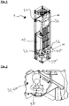
- a room air heating device 1 which has a heating device with a combustion chamber 10 .
- This combustion chamber 10 is designed as a combustion chamber 10 that is independent of ambient air. Therefore, the combustion chamber 10 is connected to a building via an exhaust pipe 39 and a fresh air supply surrounding air space connected.
- the room air heating device 1 has an air duct arrangement 30 which extends completely within the room air heating device 1 .
- the air duct arrangement 30 has an inlet 32 and an outlet 34 , with the inlet 32 being arranged completely below the outlet 34 . Numerous heatable walls 36 are formed within the air duct arrangement 30 of the room air heating device 1 .
- One of the heatable walls 36 is an outer wall of the combustion chamber 10 and a further heatable wall 36 of the air duct arrangement 30 is formed by the exhaust pipe of the combustion chamber 10 .
- the air duct arrangement 30 has at least one duct 40 which extends below the combustion chamber 10 .
- a sterilizer unit 50 is arranged within this channel 40 .
- the sterilizer unit 50 has a privacy screen and a UV-C lamp.
- FIG 2 is a detailed view of the in the figure 1 shown by means of a square box cut-out area (A) to allow a more detailed view of the sterilizer unit 50.
- the sterilizer unit 50 is located within the duct 40 of the air duct arrangement 30.
- a privacy screen is provided which prevents a direct view of the UV-C lamp of the sterilizer unit 50 .
- the sterilizer unit 50 is designed in such a way that it sterilizes and/or can sterilize at least 80 percent of the fluid flow through the air duct arrangement 30, because at least 80 percent of the flow cross section of the channel 40 is treated or sterilized by the rays emitted by the UV-C lamp.
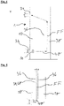
- FIG 3 Another embodiment of a room air heater 1 is shown, wherein the in the figure 3 illustrated embodiment in principle to the in the figure 1 and/or the figure 2 illustrated variants can fit. In the figure 3 however, no breakout is shown showing a view of the sterilizer unit 50 allows.
- the one in the figure 3 Room air heating device 1 shown has a conveyor 38, which has at least one fan.
- FIG 4 a section through a basic sketch of a room air heating device 1 is shown.
- a fluid flow FF can flow from the inlet 32 via the channel 40 of the air guiding arrangement 30 to the outlet 34 .
- a combustion chamber 10 is arranged inside the room air heating device 1 and has a rear wall, this rear wall representing a heatable wall 36 of the air duct arrangement 30 .
- a sterilizer unit 50 is arranged within the channel 40, which is arranged below the combustion chamber 10, which is able or designed to sterilize the fluid flow FF.
- the fluid flow FF is driven exclusively by convection, so that there is no conveying device 38 that (forcedly) conveys or establishes the fluid flow FF.
- FIG 5 a further schematic view of a room air heating device 1 is shown.
- the fluid flow FF flows through a channel 40 which extends through the combustion chamber 10 of the heating device of the room air heating device 1 .
- the channel 40 therefore has a large number of heatable walls 36 which directly delimit the channel 40 and the combustion space of the combustion chamber 10 .
- a sterilizer unit 50 of the room air heating device 1 is arranged below the combustion chamber 10 .
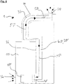
- FIG. 6 a basic arrangement of a room air heating device 1 is shown in a room, the representation in FIG figure 6 Fig. 12 is a sectional view.
- the room air heating device 1 has an air duct arrangement 30 which has at least one inlet 32 and at least one outlet 34 .
- Two sterilizer units 50 are arranged within the air duct arrangement 30, wherein the first sterilizer unit 50 can be arranged in the vicinity of the inlet 32 and the further sterilizer unit 50 can be arranged in the vicinity of the outlet 34, as in FIG figure 6 shown in principle.
- the air duct arrangement 30 is partially surrounded by the exhaust pipe 39 .
- the air duct arrangement 30 has a duct 40, the duct 40 being arranged at least partially within an exhaust gas pipe of the combustion chamber 10 that is independent of the ambient air.
- the combustion chamber 10 is in particular a biomass combustion chamber.
- the combustion chamber can be designed in such a way that it is explicitly designed for the utilization of wood fuel, in particular pellets and/or logs.
- the room air heating device 1 is expediently designed in such a way that a visual inspection of the interior of the combustion chamber 10, for example through a viewing window, is possible.
Landscapes
- Engineering & Computer Science (AREA)
- Health & Medical Sciences (AREA)
- Combustion & Propulsion (AREA)
- Chemical & Material Sciences (AREA)
- Epidemiology (AREA)
- General Engineering & Computer Science (AREA)
- Mechanical Engineering (AREA)
- Life Sciences & Earth Sciences (AREA)
- Animal Behavior & Ethology (AREA)
- General Health & Medical Sciences (AREA)
- Public Health (AREA)
- Veterinary Medicine (AREA)
- Disinfection, Sterilisation Or Deodorisation Of Air (AREA)
Applications Claiming Priority (1)
| Application Number | Priority Date | Filing Date | Title |
|---|---|---|---|
| DE102020127478.5A DE102020127478A1 (de) | 2020-10-19 | 2020-10-19 | Raumluftheizeinrichtung sowie Anordnung einer Raumluftheizeinrichtung |
Publications (1)
| Publication Number | Publication Date |
|---|---|
| EP3984565A1 true EP3984565A1 (fr) | 2022-04-20 |
Family
ID=78087150
Family Applications (1)
| Application Number | Title | Priority Date | Filing Date |
|---|---|---|---|
| EP21201881.6A Withdrawn EP3984565A1 (fr) | 2020-10-19 | 2021-10-11 | Dispositif de chauffage ambiant, ainsi qu'agencement d'un dispositif de chauffage ambiant |
Country Status (2)
| Country | Link |
|---|---|
| EP (1) | EP3984565A1 (fr) |
| DE (1) | DE102020127478A1 (fr) |
Citations (4)
| Publication number | Priority date | Publication date | Assignee | Title |
|---|---|---|---|---|
| US20030099569A1 (en) * | 2001-11-26 | 2003-05-29 | Lentz Tracy L. | System and method for controlling an ultraviolet air treatment device for return air duct applications |
| US20030188736A1 (en) * | 2002-04-09 | 2003-10-09 | Bachinski Thomas J. | Air filtration and sterilization system for a fireplace |
| DE202005004244U1 (de) * | 2004-03-11 | 2005-07-07 | Wagner, Alfred | Mobiler Komfort-Ofen |
| US9393338B2 (en) * | 2010-11-18 | 2016-07-19 | Oy Halton Group Ltd. | Air purification devices methods and systems |
Family Cites Families (3)
| Publication number | Priority date | Publication date | Assignee | Title |
|---|---|---|---|---|
| DE4007849C3 (de) | 1990-03-12 | 1999-10-07 | Hermann Hofmann | Ofen für Festbrennstoffe |
| DE19825880C5 (de) | 1998-06-10 | 2010-01-07 | Binker Materialschutz Gmbh | Thermische Schädlingsbekämpfung |
| US9459022B2 (en) | 2013-09-18 | 2016-10-04 | Supplier Support International, Inc. | Multi-component system for treating enclosed environments |
-
2020
- 2020-10-19 DE DE102020127478.5A patent/DE102020127478A1/de not_active Ceased
-
2021
- 2021-10-11 EP EP21201881.6A patent/EP3984565A1/fr not_active Withdrawn
Patent Citations (4)
| Publication number | Priority date | Publication date | Assignee | Title |
|---|---|---|---|---|
| US20030099569A1 (en) * | 2001-11-26 | 2003-05-29 | Lentz Tracy L. | System and method for controlling an ultraviolet air treatment device for return air duct applications |
| US20030188736A1 (en) * | 2002-04-09 | 2003-10-09 | Bachinski Thomas J. | Air filtration and sterilization system for a fireplace |
| DE202005004244U1 (de) * | 2004-03-11 | 2005-07-07 | Wagner, Alfred | Mobiler Komfort-Ofen |
| US9393338B2 (en) * | 2010-11-18 | 2016-07-19 | Oy Halton Group Ltd. | Air purification devices methods and systems |
Also Published As
| Publication number | Publication date |
|---|---|
| DE102020127478A1 (de) | 2022-04-21 |
Similar Documents
| Publication | Publication Date | Title |
|---|---|---|
| DE2519998A1 (de) | Transportable heizvorrichtung | |
| DE1802196A1 (de) | Brennereinheit fuer Heizkoerper | |
| DE2321236C2 (de) | Katalytisches Raumheizgerät zum Heizen eines Aufenthaltsraumes | |
| EP3984565A1 (fr) | Dispositif de chauffage ambiant, ainsi qu'agencement d'un dispositif de chauffage ambiant | |
| DE10254565B4 (de) | Kaminofen und seine Verwendung | |
| EP2500658B1 (fr) | Dispositif de chauffage comprenant une chambre de combustion destinée à la combustion de matériau combustible à base de biomasse | |
| EP1541179A1 (fr) | Dispositif de stérilisation | |
| EP1816411A2 (fr) | Dispositif de chauffage d'espace pour une caravane | |
| EP2253891B1 (fr) | Chauffage infrarouge, notamment pour le chauffage de halls | |
| EP1798470B1 (fr) | Dispositif de chauffage et son procédé de fonctionnement | |
| DE29500595U1 (de) | Backofen mit einem einen Gebläsebrenner aufweisenden Dampferzeuger | |
| DE202016104327U1 (de) | Mobiler Heizstrahler | |
| EP2351966B1 (fr) | Système d'échangeur de chaleur | |
| CH499317A (de) | Saunakabine | |
| EP3283346B1 (fr) | Bloc sanitaire pour véhicule ferroviaire | |
| DE202020107000U1 (de) | UV-C-Modul zur Raumluftdesinfektion bzw. Entkeimung von Luft durch Behandlung mit ultravioletter Strahlung | |
| EP1753471A1 (fr) | Conteneur de decontamination mobile | |
| AT404506B (de) | Heizungsanlage | |
| DE102009044681A1 (de) | Heizelement, insbesondere eines Dekorationskamins (Dekokamins) | |
| DE102006011252B4 (de) | Brennofen | |
| DE19503426A1 (de) | Transportabler Warmlufterzeuger | |
| EP1336801A1 (fr) | Méthode et dispositif pour séparer un foyer de l'extérieur au moyen d'un rideau d'air | |
| DE69201700T2 (de) | Vorrichtung zur raumtemperatursteuerung. | |
| DE202021102540U1 (de) | In Schornstein integrierter Pelletofen | |
| EP0171028A2 (fr) | Installation de chauffage |
Legal Events
| Date | Code | Title | Description |
|---|---|---|---|
| PUAI | Public reference made under article 153(3) epc to a published international application that has entered the european phase |
Free format text: ORIGINAL CODE: 0009012 |
|
| STAA | Information on the status of an ep patent application or granted ep patent |
Free format text: STATUS: THE APPLICATION HAS BEEN PUBLISHED |
|
| AK | Designated contracting states |
Kind code of ref document: A1 Designated state(s): AL AT BE BG CH CY CZ DE DK EE ES FI FR GB GR HR HU IE IS IT LI LT LU LV MC MK MT NL NO PL PT RO RS SE SI SK SM TR |
|
| STAA | Information on the status of an ep patent application or granted ep patent |
Free format text: STATUS: REQUEST FOR EXAMINATION WAS MADE |
|
| 17P | Request for examination filed |
Effective date: 20221019 |
|
| RBV | Designated contracting states (corrected) |
Designated state(s): AL AT BE BG CH CY CZ DE DK EE ES FI FR GB GR HR HU IE IS IT LI LT LU LV MC MK MT NL NO PL PT RO RS SE SI SK SM TR |
|
| STAA | Information on the status of an ep patent application or granted ep patent |
Free format text: STATUS: THE APPLICATION HAS BEEN WITHDRAWN |
|
| 18W | Application withdrawn |
Effective date: 20230406 |