EP3991905A1 - Système et procédé de traitement au laser - Google Patents
Système et procédé de traitement au laser Download PDFInfo
- Publication number
- EP3991905A1 EP3991905A1 EP21783385.4A EP21783385A EP3991905A1 EP 3991905 A1 EP3991905 A1 EP 3991905A1 EP 21783385 A EP21783385 A EP 21783385A EP 3991905 A1 EP3991905 A1 EP 3991905A1
- Authority
- EP
- European Patent Office
- Prior art keywords
- workpiece
- bessel beam
- laser
- focus line
- laser processing
- Prior art date
- Legal status (The legal status is an assumption and is not a legal conclusion. Google has not performed a legal analysis and makes no representation as to the accuracy of the status listed.)
- Pending
Links
Images


Classifications
-
- B—PERFORMING OPERATIONS; TRANSPORTING
- B23—MACHINE TOOLS; METAL-WORKING NOT OTHERWISE PROVIDED FOR
- B23K—SOLDERING OR UNSOLDERING; WELDING; CLADDING OR PLATING BY SOLDERING OR WELDING; CUTTING BY APPLYING HEAT LOCALLY, e.g. FLAME CUTTING; WORKING BY LASER BEAM
- B23K26/00—Working by laser beam, e.g. welding, cutting or boring
- B23K26/08—Devices involving relative movement between laser beam and workpiece
- B23K26/082—Scanning systems, i.e. devices involving movement of the laser beam relative to the laser head
-
- B—PERFORMING OPERATIONS; TRANSPORTING
- B23—MACHINE TOOLS; METAL-WORKING NOT OTHERWISE PROVIDED FOR
- B23K—SOLDERING OR UNSOLDERING; WELDING; CLADDING OR PLATING BY SOLDERING OR WELDING; CUTTING BY APPLYING HEAT LOCALLY, e.g. FLAME CUTTING; WORKING BY LASER BEAM
- B23K26/00—Working by laser beam, e.g. welding, cutting or boring
- B23K26/02—Positioning or observing the workpiece, e.g. with respect to the point of impact; Aligning, aiming or focusing the laser beam
- B23K26/04—Automatically aligning, aiming or focusing the laser beam, e.g. using the back-scattered light
- B23K26/046—Automatically focusing the laser beam
-
- B—PERFORMING OPERATIONS; TRANSPORTING
- B23—MACHINE TOOLS; METAL-WORKING NOT OTHERWISE PROVIDED FOR
- B23K—SOLDERING OR UNSOLDERING; WELDING; CLADDING OR PLATING BY SOLDERING OR WELDING; CUTTING BY APPLYING HEAT LOCALLY, e.g. FLAME CUTTING; WORKING BY LASER BEAM
- B23K26/00—Working by laser beam, e.g. welding, cutting or boring
- B23K26/02—Positioning or observing the workpiece, e.g. with respect to the point of impact; Aligning, aiming or focusing the laser beam
- B23K26/06—Shaping the laser beam, e.g. by masks or multi-focusing
- B23K26/062—Shaping the laser beam, e.g. by masks or multi-focusing by direct control of the laser beam
- B23K26/0622—Shaping the laser beam, e.g. by masks or multi-focusing by direct control of the laser beam by shaping pulses
- B23K26/0624—Shaping the laser beam, e.g. by masks or multi-focusing by direct control of the laser beam by shaping pulses using ultrashort pulses, i.e. pulses of 1 ns or less
-
- B—PERFORMING OPERATIONS; TRANSPORTING
- B23—MACHINE TOOLS; METAL-WORKING NOT OTHERWISE PROVIDED FOR
- B23K—SOLDERING OR UNSOLDERING; WELDING; CLADDING OR PLATING BY SOLDERING OR WELDING; CUTTING BY APPLYING HEAT LOCALLY, e.g. FLAME CUTTING; WORKING BY LASER BEAM
- B23K26/00—Working by laser beam, e.g. welding, cutting or boring
- B23K26/02—Positioning or observing the workpiece, e.g. with respect to the point of impact; Aligning, aiming or focusing the laser beam
- B23K26/06—Shaping the laser beam, e.g. by masks or multi-focusing
- B23K26/064—Shaping the laser beam, e.g. by masks or multi-focusing by means of optical elements, e.g. lenses, mirrors or prisms
- B23K26/0643—Shaping the laser beam, e.g. by masks or multi-focusing by means of optical elements, e.g. lenses, mirrors or prisms comprising mirrors
-
- B—PERFORMING OPERATIONS; TRANSPORTING
- B23—MACHINE TOOLS; METAL-WORKING NOT OTHERWISE PROVIDED FOR
- B23K—SOLDERING OR UNSOLDERING; WELDING; CLADDING OR PLATING BY SOLDERING OR WELDING; CUTTING BY APPLYING HEAT LOCALLY, e.g. FLAME CUTTING; WORKING BY LASER BEAM
- B23K26/00—Working by laser beam, e.g. welding, cutting or boring
- B23K26/02—Positioning or observing the workpiece, e.g. with respect to the point of impact; Aligning, aiming or focusing the laser beam
- B23K26/06—Shaping the laser beam, e.g. by masks or multi-focusing
- B23K26/064—Shaping the laser beam, e.g. by masks or multi-focusing by means of optical elements, e.g. lenses, mirrors or prisms
- B23K26/0648—Shaping the laser beam, e.g. by masks or multi-focusing by means of optical elements, e.g. lenses, mirrors or prisms comprising lenses
-
- B—PERFORMING OPERATIONS; TRANSPORTING
- B23—MACHINE TOOLS; METAL-WORKING NOT OTHERWISE PROVIDED FOR
- B23K—SOLDERING OR UNSOLDERING; WELDING; CLADDING OR PLATING BY SOLDERING OR WELDING; CUTTING BY APPLYING HEAT LOCALLY, e.g. FLAME CUTTING; WORKING BY LASER BEAM
- B23K26/00—Working by laser beam, e.g. welding, cutting or boring
- B23K26/02—Positioning or observing the workpiece, e.g. with respect to the point of impact; Aligning, aiming or focusing the laser beam
- B23K26/06—Shaping the laser beam, e.g. by masks or multi-focusing
- B23K26/064—Shaping the laser beam, e.g. by masks or multi-focusing by means of optical elements, e.g. lenses, mirrors or prisms
- B23K26/0652—Shaping the laser beam, e.g. by masks or multi-focusing by means of optical elements, e.g. lenses, mirrors or prisms comprising prisms
-
- B—PERFORMING OPERATIONS; TRANSPORTING
- B23—MACHINE TOOLS; METAL-WORKING NOT OTHERWISE PROVIDED FOR
- B23K—SOLDERING OR UNSOLDERING; WELDING; CLADDING OR PLATING BY SOLDERING OR WELDING; CUTTING BY APPLYING HEAT LOCALLY, e.g. FLAME CUTTING; WORKING BY LASER BEAM
- B23K26/00—Working by laser beam, e.g. welding, cutting or boring
- B23K26/02—Positioning or observing the workpiece, e.g. with respect to the point of impact; Aligning, aiming or focusing the laser beam
- B23K26/06—Shaping the laser beam, e.g. by masks or multi-focusing
- B23K26/0665—Shaping the laser beam, e.g. by masks or multi-focusing by beam condensation on the workpiece, e.g. for focusing
-
- B—PERFORMING OPERATIONS; TRANSPORTING
- B23—MACHINE TOOLS; METAL-WORKING NOT OTHERWISE PROVIDED FOR
- B23K—SOLDERING OR UNSOLDERING; WELDING; CLADDING OR PLATING BY SOLDERING OR WELDING; CUTTING BY APPLYING HEAT LOCALLY, e.g. FLAME CUTTING; WORKING BY LASER BEAM
- B23K26/00—Working by laser beam, e.g. welding, cutting or boring
- B23K26/02—Positioning or observing the workpiece, e.g. with respect to the point of impact; Aligning, aiming or focusing the laser beam
- B23K26/06—Shaping the laser beam, e.g. by masks or multi-focusing
- B23K26/067—Dividing the beam into multiple beams, e.g. multi-focusing
-
- B—PERFORMING OPERATIONS; TRANSPORTING
- B23—MACHINE TOOLS; METAL-WORKING NOT OTHERWISE PROVIDED FOR
- B23K—SOLDERING OR UNSOLDERING; WELDING; CLADDING OR PLATING BY SOLDERING OR WELDING; CUTTING BY APPLYING HEAT LOCALLY, e.g. FLAME CUTTING; WORKING BY LASER BEAM
- B23K26/00—Working by laser beam, e.g. welding, cutting or boring
- B23K26/02—Positioning or observing the workpiece, e.g. with respect to the point of impact; Aligning, aiming or focusing the laser beam
- B23K26/06—Shaping the laser beam, e.g. by masks or multi-focusing
- B23K26/073—Shaping the laser spot
- B23K26/0734—Shaping the laser spot into an annular shape
-
- B—PERFORMING OPERATIONS; TRANSPORTING
- B23—MACHINE TOOLS; METAL-WORKING NOT OTHERWISE PROVIDED FOR
- B23K—SOLDERING OR UNSOLDERING; WELDING; CLADDING OR PLATING BY SOLDERING OR WELDING; CUTTING BY APPLYING HEAT LOCALLY, e.g. FLAME CUTTING; WORKING BY LASER BEAM
- B23K26/00—Working by laser beam, e.g. welding, cutting or boring
- B23K26/08—Devices involving relative movement between laser beam and workpiece
- B23K26/082—Scanning systems, i.e. devices involving movement of the laser beam relative to the laser head
- B23K26/0821—Scanning systems, i.e. devices involving movement of the laser beam relative to the laser head using multifaceted mirrors, e.g. polygonal mirror
-
- B—PERFORMING OPERATIONS; TRANSPORTING
- B23—MACHINE TOOLS; METAL-WORKING NOT OTHERWISE PROVIDED FOR
- B23K—SOLDERING OR UNSOLDERING; WELDING; CLADDING OR PLATING BY SOLDERING OR WELDING; CUTTING BY APPLYING HEAT LOCALLY, e.g. FLAME CUTTING; WORKING BY LASER BEAM
- B23K26/00—Working by laser beam, e.g. welding, cutting or boring
- B23K26/08—Devices involving relative movement between laser beam and workpiece
- B23K26/083—Devices involving movement of the workpiece in at least one axial direction
- B23K26/0853—Devices involving movement of the workpiece in at least two axial directions, e.g. in a plane
-
- B—PERFORMING OPERATIONS; TRANSPORTING
- B23—MACHINE TOOLS; METAL-WORKING NOT OTHERWISE PROVIDED FOR
- B23K—SOLDERING OR UNSOLDERING; WELDING; CLADDING OR PLATING BY SOLDERING OR WELDING; CUTTING BY APPLYING HEAT LOCALLY, e.g. FLAME CUTTING; WORKING BY LASER BEAM
- B23K26/00—Working by laser beam, e.g. welding, cutting or boring
- B23K26/36—Removing material
- B23K26/38—Removing material by boring or cutting
- B23K26/382—Removing material by boring or cutting by boring
-
- B—PERFORMING OPERATIONS; TRANSPORTING
- B23—MACHINE TOOLS; METAL-WORKING NOT OTHERWISE PROVIDED FOR
- B23K—SOLDERING OR UNSOLDERING; WELDING; CLADDING OR PLATING BY SOLDERING OR WELDING; CUTTING BY APPLYING HEAT LOCALLY, e.g. FLAME CUTTING; WORKING BY LASER BEAM
- B23K26/00—Working by laser beam, e.g. welding, cutting or boring
- B23K26/36—Removing material
- B23K26/40—Removing material taking account of the properties of the material involved
- B23K26/402—Removing material taking account of the properties of the material involved involving non-metallic material, e.g. isolators
-
- C—CHEMISTRY; METALLURGY
- C03—GLASS; MINERAL OR SLAG WOOL
- C03B—MANUFACTURE, SHAPING, OR SUPPLEMENTARY PROCESSES
- C03B33/00—Severing cooled glass
- C03B33/02—Cutting or splitting sheet glass or ribbons; Apparatus or machines therefor
- C03B33/023—Cutting or splitting sheet glass or ribbons; Apparatus or machines therefor the sheet or ribbon being in a horizontal position
-
- B—PERFORMING OPERATIONS; TRANSPORTING
- B23—MACHINE TOOLS; METAL-WORKING NOT OTHERWISE PROVIDED FOR
- B23K—SOLDERING OR UNSOLDERING; WELDING; CLADDING OR PLATING BY SOLDERING OR WELDING; CUTTING BY APPLYING HEAT LOCALLY, e.g. FLAME CUTTING; WORKING BY LASER BEAM
- B23K2101/00—Articles made by soldering, welding or cutting
- B23K2101/36—Electric or electronic devices
- B23K2101/40—Semiconductor devices
-
- B—PERFORMING OPERATIONS; TRANSPORTING
- B23—MACHINE TOOLS; METAL-WORKING NOT OTHERWISE PROVIDED FOR
- B23K—SOLDERING OR UNSOLDERING; WELDING; CLADDING OR PLATING BY SOLDERING OR WELDING; CUTTING BY APPLYING HEAT LOCALLY, e.g. FLAME CUTTING; WORKING BY LASER BEAM
- B23K2103/00—Materials to be soldered, welded or cut
- B23K2103/50—Inorganic materials other than metals or composite materials
- B23K2103/54—Glass
-
- B—PERFORMING OPERATIONS; TRANSPORTING
- B23—MACHINE TOOLS; METAL-WORKING NOT OTHERWISE PROVIDED FOR
- B23K—SOLDERING OR UNSOLDERING; WELDING; CLADDING OR PLATING BY SOLDERING OR WELDING; CUTTING BY APPLYING HEAT LOCALLY, e.g. FLAME CUTTING; WORKING BY LASER BEAM
- B23K2103/00—Materials to be soldered, welded or cut
- B23K2103/50—Inorganic materials other than metals or composite materials
- B23K2103/56—Inorganic materials other than metals or composite materials being semiconducting
-
- B—PERFORMING OPERATIONS; TRANSPORTING
- B23—MACHINE TOOLS; METAL-WORKING NOT OTHERWISE PROVIDED FOR
- B23K—SOLDERING OR UNSOLDERING; WELDING; CLADDING OR PLATING BY SOLDERING OR WELDING; CUTTING BY APPLYING HEAT LOCALLY, e.g. FLAME CUTTING; WORKING BY LASER BEAM
- B23K26/00—Working by laser beam, e.g. welding, cutting or boring
- B23K26/36—Removing material
- B23K26/38—Removing material by boring or cutting
Definitions
- the present invention relates to a processing system and a processing method for processing a workpiece using a laser.
- a laser is widely used for processing such as for cutting a processing object or forming a hole.
- an optical element such as a lens is used to form a laser beam of a desired shape suitable for processing work, and the formed laser beam is irradiated to a workpiece.
- the laser beam may be efficiently used for the processing such as cutting of brittle materials that are difficult to process such as transparent glass substrates, or drilling of holes.
- the laser beam may be efficiently used for the processing such as cutting of brittle materials that are difficult to process such as transparent glass substrates, or drilling of holes.
- cracks are generated in the workpiece by the laser and the cracks propagate, thereby cutting the workpiece. Accordingly, there is a problem that the cracks can be generated non-uniform ly and the incision surface is uneven.
- One aspect of the present invention is to provide a system and a method capable of processing a workpiece (an object to be processed) at high speed by using a laser beam.
- a laser processing system includes: a laser unit emitting a laser beam; an optical unit disposed on a propagation path of the laser beam and modulating the incident laser beam into a Bessel beam; a stage on which a workpiece to be processed with the Bessel beam emitted from the optical unit is mounted; and a control unit for controlling the operations of the laser unit, the optical unit, and the stage, wherein the optical unit is configured to position a focus line of the emitted Bessel beam on the workpiece and to move the focus line positioned on the workpiece within a predetermined range.
- the optical unit may maintain the angle between the focus line of the emitted Bessel beam and the processed surface of the workpiece in the range of 80-100 degrees.
- the optical unit may include a first optical unit that modulates the incident laser beam into the Bessel beam, and a second optical unit that moves the focus line of the emitted Bessel beam in a direction intersecting the focus line on the workpiece.
- the first optical unit may include a first optical element that modulates the incident laser beam into a Bessel beam, and a second optical element that advances the optical axis of the Bessel beam passing through the first optical element in parallel.
- the second optical unit may include a scanner moving the path of the Bessel beam that has passed through the first optical unit, and a focusing lens positioning the focus line of the Bessel beam emitted from the scanner on the workpiece.
- the control unit may drive the scanner so that the focus line of the emitted Bessel beam moves in at least two axis directions and simultaneously drives the stage in the at least two axis directions.
- the diameter of the Bessel beam entering the scanner may be 3-30 mm.
- the focal length of the focusing lens may be 10-300 mm.
- the distance that the focus line of the Bessel beam emitted from the scanner moves on the workpiece may be 1 ⁇ m-30 mm.
- the scanner may include a plurality of mirrors whose angle is adjusted by the control unit.
- the workpiece may be in a form of a flat plate.
- a laser processing method as a method of processing a workpiece by irradiating a laser beam includes: modulating the laser beam having a circular cross-section perpendicular to a direction of the laser beam into a Bessel beam having an annular cross-section; and irradiating the Bessel beam to the workpiece and processing the workpiece while a focus line of the Bessel beam is positioned on the workpiece to be processed, and in the processing, the focus line of the Bessel beam positioned on the workpiece moves.
- the workpiece may move and the focus line of the Bessel beam may simultaneously move.
- the processing may include setting a processing path corresponding to the shape to process the workpiece, separating the predetermined processing path into a first path through which the focus line of the Bessel beam moves and a second path through which the workpiece moves, and moving the focus line of the Bessel beam to the first path and simultaneously moving the workpiece to the second path, thereby processing the workpiece along the processing path.
- the angle between the focus line of the Bessel beam and the processed surface of the workpiece may be maintained in the range of 80-100 degrees.
- the distance that the focus line of the Bessel beam positioned on the workpiece moves on the workpiece may be 1 ⁇ m-30 mm.
- the processing may include moving a path of the Bessel beam that is reflected by adjusting an angle of a mirror positioned on the path of the Bessel beam for scanning, and focusing the reflected Bessel beam onto the workpiece.
- the diameter of the Bessel beam incident to the mirror may be 3-30 mm.
- a focal length may be 10-300 mm.
- the workpiece may be processed at a high speed by scanning the Bessel beam to expand the irradiation area.
- the processing quality may be improved.
- front and rear are named based on a beam propagation direction, and the direction accessing the workpiece is defined as “the rear”.
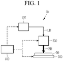
- FIG. 1 is a schematic diagram of a laser processing system according to an embodiment of the present invention.
- the laser processing system 10 includes a laser unit 100, an optical unit 200, a stage 300, and a control unit 400.
- a laser beam LB emitted from the laser unit 100 is modulated into a Bessel beam BB shape through the optical unit 200, and the Bessel beam BB is irradiated to the workpiece 50 fixed to the stage 300 to process the workpiece 50.
- the Bessel beam BB irradiated to the workpiece 50 may process the workpiece 50 at a high speed while scanning a predetermined range of the workpiece 50.
- the control unit 400 controls the beam BB scans and the stage 300 is simultaneously driven, so that high-speed and precise processing is possible.
- the laser unit 100 is configured to emit the laser beam LB for processing the workpiece 50, and may generate the laser beam having a predetermined pulse to be emitted in a form of a beam.
- the emitted laser beam LB may have a pulse (e.g., an ultra-short pulse) or a burst pulse having a wavelength, energy, and a duration suitable for processing the workpiece 50.
- the laser beam LB may have a circular shape or a Gaussian beam shape when viewed in the traveling direction (a cross-section perpendicular to the traveling direction).
- the workpiece 50 may have a flat plate shape, for example, a transparent glass substrate.
- the workpiece 50 is not limited to the transparent glass substrate, and may include various materials such as an opaque substrate, a metal material, and a semiconductor wafer.
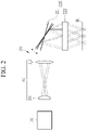
- FIG. 2 is a view showing an optical unit of a laser processing system according to an embodiment of the present invention
- FIG. 3 is a view showing a state of being scanned through an optical unit among a laser processing system according to an embodiment of the present invention
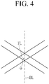
- FIG. 4 is an enlarged view of a portion IV of FIG. 3 .
- the optical unit 200 is disposed on the propagation path of the laser beam LB emitted from the laser unit 100 and is configured to modulate the incident laser beam LB to the Bessel beam BB. According to an embodiment of the present invention, the optical unit 200 may be configured to move the focus line FL positioned on the workpiece 50 by a predetermined range while positioning the focus line FL of the emitted beam BB on the workpiece 50.
- the focus line FL' in this specification means a condensing length or a focus depth of the Bessel beam incident on the workpiece.
- the optical unit 200 may include a first optical unit 210 and a second optical unit 220.
- the first optical unit 210 is an optical unit that modulates the laser beam LB into the Bessel beam BB, and may include a first optical element 211 and a second optical element 212 disposed to the rear of the first optical element 211.
- the first optical element 211 may be a diffraction element for modulating the laser beam LB into the Bessel beam BB, for example a conical prism or an axicon lens. Therefore, while the laser beam LB is diffracted while passing through the first optical element 211 (when being viewed in the beam propagation direction, or the cross-section perpendicular to the beam propagation direction), it may be modulated into the annular (ring) Bessel beam BB.
- the first optical element 211 is not limited to the conical prism or the axicon lens, and various optical elements capable of modulating the laser beam LB into the Bessel beam BB may be used.
- the second optical element 212 capable of restricting the expansion of the area of the Bessel beam BL suitable for machining the workpiece 50 may be provided behind the first optical element 211. That is, the second optical element 212 may be an optical element for parallelly advancing the optical axis of the Bessel beam BL emitted from the first optical element 211, for example, a collimating lens or a collimating lens.
- the optical axis of the Bessel beam BB passing through the second optical element 212 may be arranged in parallel, and then be incident to the second optical unit 220.
- the above-described first optical element 211 and second optical element 212 may be appropriately selected or adjusted in each optical property, arrangement interval, etc., thereby the diameter of the Bessel beam BB passing through the second optical element 212 to be incident to the second optical unit 220 or the scanner 221 may be in the range of 3-30 mm.
- the second optical unit 220 is configured to move the focus line FL of the emitted beam BB on the workpiece 50, and may include a scanner 221 and a focusing lens 222.
- the focus line FL of the Bessel beam BB emitted through the second optical unit 220 may be positioned on the workpiece 50, and the focus line FL may be moved in a direction intersecting the focus line FL while remaining positioned on the workpiece 50, and accordingly, the workpiece 50 may be machined while scanning the vessel beam BB within a predetermined range on the workpiece 50.
- the scanner 221 may move the path of the Bessel beam BB passing through the first optical unit 210.
- the scanner 221 may continuously change the optical axis direction of the incident Bessel beam BB within a predetermined angle range, and through this, the scanner 221 may scan the emitted Bessel beam BB within a predetermined range.
- the scanner 221 may include a plurality of mirrors whose angle is adjusted. Accordingly, the Bessel beam BB incident to the scanner 221 is reflected by a plurality of mirrors, and the reflection angle of the reflected Bessel beam BB, by adjusting the angle of the mirror, may be adjusted.
- the scanner 221 may include at least two mirrors that are respectively rotatable along the rotation axes arranged in at least two axis directions and may be configured as, for example, galvano mirrors.
- the configuration of the scanner 221 is not limited to a galvanometer, and may include various devices capable of scanning the emitted Bessel beam BB within a predetermined area range.
- the Bessel beam BB whose path is changed through the scanner 221 may be focused on the workpiece 50 by the focusing lens 222.
- the focusing lens 222 may be disposed between the scanner 221 and the workpiece 50, and the focus line FL of the Bessel beam BB emitted from the scanner 221 may be positioned on the workpiece 50. As will be described later, the focusing lens 222 may keep the focus line FL of the Bessel beam BB as perpendicular as possible to the processed surface BL of the workpiece.
- the Bessel beam BB is focused by the focusing lens 222, so that the focus line FL of the Bessel beam BB may be positioned on the processed surface BL of the workpiece 50.
- the focal length of the focusing lens 222 may be configured in a range of 10-300 mm. Accordingly, the workpiece 50 may be positioned and machined to be spaced apart by a distance corresponding to the focal length of the focusing lens 222.
- the processed surface of the workpiece 50 is indicated by a reference numeral BL.
- the processed surface BL does not mean an exterior side where the processing of the workpiece 50 starts, but it means a virtual surface including an arbitrary point among the parts to be processed on the workpiece 50.
- the workpiece 50 may have a predetermined thickness, and depending on the processing method, the focus line FL of the Bessel beam BB positioned on the workpiece 50 may be positioned over the entire thickness of the workpiece 50 or only a portion of the thickness of the workpiece 50.
- the predetermined range of the workpiece 50 may be scanned.
- the state that the focus line FL of the Bessel beam BB is poisoned on the workpiece 50 may be maintained, and the distance that the focus line FL of the Bessel beam BB is moved on the workpiece 50 (or on the processed surfaced) may be the range of 1 ⁇ m-30 mm.
- the movement distance is a movement distance in one direction (e.g., the x-axis direction or the y-axis direction in FIG. 5 ).
- the Bessel beam BB may process while scanning a predetermined range on the x and y axes of the workpiece 50.
- the angle ⁇ between the focus line FL of the beam BB positioned on the workpiece 50 and the processed surface BL of the workpiece may be close to 90 degrees. More specifically, according to an embodiment of the present invention, while the focus line FL of the Bessel beam BB is moved (scanning) in a predetermined range on the workpiece 50, the angle ⁇ between the focus line FL of the beam BB and the processed surface BL of the workpiece may be maintained in the range of 80-100 degrees.
- the angle ⁇ between the focus line FL of the Bessel beam BB and the processed surface BL of the workpiece may be maintained in the range of 80-100 degrees.
- the Bessel beam BB passing through the focusing lens 222 is incident on the processed surface BL of the workpiece at the angle close to vertical, and an angle deviating from the vertical direction may be maintained within a range of 10 degrees or less.
- the Bessel beam BB generated by the first optical element 211 which is a diffraction element, causes an interference effect in a predetermined processing position and range, and maintaining the characteristic uniformly affects the processing quality. Therefore, for excellent and uniform processing quality, it is important how the vertical degree of the interference beam incident on the processed surface of the workpiece 50 is maintained. According to an embodiment of the present invention, while the focus line FL of the Bessel beam BB positioned on the workpiece 50 scans the processed surface of the workpiece, since the angle ⁇ formed with the processed surface BL of the workpiece is maintained in the range of 80-100 degrees, it is possible to maintain excellent and uniform processing quality while performing high-speed processing.
- the workpiece 50 may be fixed to the stage 300. That is, the stage 300 is a part on which the workpiece 50 is mounted to fix the position of the workpiece 50.
- the above-described laser unit 100, optical unit 200, and stage 300 may be controlled through the control unit 400.
- the control unit 400 may adjust the wavelength, energy, and duration of the pulse of the laser beam LB generated by the laser unit 100 to match the characteristic of the workpiece 50.
- control unit 400 may drive the scanner 221 to move the Bessel beam BB incident on the workpiece 50.
- the control unit 400 may drive the scanner 221 to move the focus line FL of the Bessel beam BB in at least two axes (the x-axis and the y-axis) directions on the processed surface BL.
- the control unit 400 may control a driving means for rotating each of a plurality of mirrors in a predetermined angle range (e.g., a driving motor).
- a driving means for rotating each of a plurality of mirrors in a predetermined angle range e.g., a driving motor.
- control unit 400 may move the stage 300 to which the workpiece 50 is fixed.
- the control unit 400 may drive the scanner 221 and simultaneously drive the stage 300.
- the control unit 400 may rotate the mirror at a high speed in a predetermined angle range so that the angle of the mirror of the scanner 221 is continuously adjusted, and simultaneously drive the stage 300 at a low speed in at least two axes (the x-axis and the y-axis) directions.
- the stage 300 (compared to the scanner) has a slow response and is driven at a low speed and may have a wide processing area
- the scanner 221 compared to the stage
- an embodiment of the present invention enables a more precise process and saves processing time by simultaneously controlling the stage 300 and the scanner 221 compared to the conventional method of processing the workpiece by moving only the stage 300.
- the processing may be performed regardless of the size of the workpiece.
- FIG. 5 is a view showing a process that a workpiece is processed through a laser processing method according to an embodiment of the present invention.
- FIG. 5 is showing the process of processing a shape, and shows that the processing proceeds from the left to the right.
- the first processing path PL1 through the driving of the scanner 221 and the second processing path PL2 through the driving of the stage 300 may be simultaneously performed. That is, when only the stage 300 is moved for the processing path PL of the final quadrangle, even if the control signal is transmitted from the control unit 400 (referring to FIG. 1 ) to the stage 300, due to the limitation of the response and the movement speed (acceleration), the processing quality may be deteriorated in an area such as the edge of the final quadrangle processing path PL.
- control unit 400 controls the stage 300 moving in the wide processing area and simultaneously controls the scanner 221 (e.g. , the mirror that pivots and rotates around the rotation axis) having the responsiveness and the fast movement speed (the acceleration) while moving in the relatively narrow processing area, thereby the final processing path PL with improved quality while reducing the processing time may be processed.
- the scanner 221 e.g. , the mirror that pivots and rotates around the rotation axis
- the electrical control signal transmitted from the control unit 400 to the stage 300 and the scanner 221 may be separated into a high-frequency component and a low-frequency component through a filter.
- the high-frequency component may be a signal of the first processing path PL1, which is a high-speed movement path, and may be transmitted to the scanner 221.
- the low-frequency component may be a signal of the second processing path PL2, which is a low-speed movement path, and may be transmitted to the stage 300.
- the control unit 400 simultaneously controls the scanner 221 and the stage 300, the first processing path PL1 through the scanner 221 and the second processing path PL2 through the stage 300 may be combined to process the final processing path PL.
- the processing may be performed without being limited to the field of view (FOV) of the scanner 221. Therefore, according to an embodiment of the present invention, by synchronizing and simultaneously controlling the stage 300 and the scanner 221, it is possible to precisely process the workpiece regardless of the size of the workpiece.
- FOV field of view
- the workpiece 50 such as a glass substrate may be precisely processed.
- the workpiece 50 may be processed at high speed by scanning the Bessel beam BB irradiated to the workpiece 50 and expanding the irradiation area.
- a precise shape may be machined and the processing time may be saved.
Landscapes
- Physics & Mathematics (AREA)
- Optics & Photonics (AREA)
- Engineering & Computer Science (AREA)
- Plasma & Fusion (AREA)
- Mechanical Engineering (AREA)
- Chemical & Material Sciences (AREA)
- Materials Engineering (AREA)
- Organic Chemistry (AREA)
- Laser Beam Processing (AREA)
- Electrical Discharge Machining, Electrochemical Machining, And Combined Machining (AREA)
Applications Claiming Priority (2)
| Application Number | Priority Date | Filing Date | Title |
|---|---|---|---|
| KR1020200114708A KR102375235B1 (ko) | 2020-09-08 | 2020-09-08 | 레이저 가공 시스템 및 방법 |
| PCT/KR2021/004300 WO2022055062A1 (fr) | 2020-09-08 | 2021-04-06 | Système et procédé de traitement au laser |
Publications (2)
| Publication Number | Publication Date |
|---|---|
| EP3991905A1 true EP3991905A1 (fr) | 2022-05-04 |
| EP3991905A4 EP3991905A4 (fr) | 2023-01-04 |
Family
ID=80631871
Family Applications (1)
| Application Number | Title | Priority Date | Filing Date |
|---|---|---|---|
| EP21783385.4A Pending EP3991905A4 (fr) | 2020-09-08 | 2021-04-06 | Système et procédé de traitement au laser |
Country Status (7)
| Country | Link |
|---|---|
| US (1) | US12303999B2 (fr) |
| EP (1) | EP3991905A4 (fr) |
| JP (1) | JP2023552942A (fr) |
| KR (1) | KR102375235B1 (fr) |
| CN (1) | CN114667196A (fr) |
| TW (1) | TWI803934B (fr) |
| WO (1) | WO2022055062A1 (fr) |
Families Citing this family (9)
| Publication number | Priority date | Publication date | Assignee | Title |
|---|---|---|---|---|
| US20250339922A1 (en) * | 2022-05-10 | 2025-11-06 | Philoptics Co., Ltd. | Method for forming precise through-hole at high speed by using infrared laser |
| EP4523837A4 (fr) * | 2022-05-10 | 2025-09-10 | Philoptics Co Ltd | Procédé de formation d'un trou traversant précis à haute vitesse à l'aide d'un laser infrarouge |
| CN115555708B (zh) * | 2022-10-18 | 2026-03-13 | 清华大学 | 反射式贝塞尔激光微纳加工装置及方法 |
| CN115463905B (zh) * | 2022-10-25 | 2023-11-24 | 武汉锐科光纤激光技术股份有限公司 | 一种激光清洗控制系统及方法 |
| TWI863045B (zh) * | 2022-11-30 | 2024-11-21 | 財團法人工業技術研究院 | 材料改質加工裝置與凹洞成形方法 |
| WO2025170341A1 (fr) | 2024-02-06 | 2025-08-14 | 주식회사 필옵틱스 | Système et procédé d'usinage circulaire de matériau cassant transparent à l'aide d'un laser ultrarapide |
| KR20250173670A (ko) | 2024-06-04 | 2025-12-11 | 주식회사 이오테크닉스 | 레이저 가공방법 |
| JP7728533B1 (ja) * | 2025-02-25 | 2025-08-25 | 公立大学法人公立諏訪東京理科大学 | 光学装置及び微細改質領域形成方法 |
| JP7769351B1 (ja) * | 2025-02-25 | 2025-11-13 | 公立大学法人公立諏訪東京理科大学 | 光学装置 |
Family Cites Families (19)
| Publication number | Priority date | Publication date | Assignee | Title |
|---|---|---|---|---|
| DE69418248T2 (de) * | 1993-06-03 | 1999-10-14 | Hamamatsu Photonics Kk | Optisches Laser-Abtastsystem mit Axikon |
| US5751585A (en) * | 1995-03-20 | 1998-05-12 | Electro Scientific Industries, Inc. | High speed, high accuracy multi-stage tool positioning system |
| US6706999B1 (en) * | 2003-02-24 | 2004-03-16 | Electro Scientific Industries, Inc. | Laser beam tertiary positioner apparatus and method |
| JP4418282B2 (ja) | 2004-03-31 | 2010-02-17 | 株式会社レーザーシステム | レーザ加工方法 |
| JP4467633B2 (ja) | 2008-03-24 | 2010-05-26 | 丸文株式会社 | ビーム加工装置、ビーム加工方法およびビーム加工基板 |
| FR2989294B1 (fr) | 2012-04-13 | 2022-10-14 | Centre Nat Rech Scient | Dispositif et methode de nano-usinage par laser |
| EP2754524B1 (fr) | 2013-01-15 | 2015-11-25 | Corning Laser Technologies GmbH | Procédé et dispositif destinés au traitement basé sur laser de substrats plats, galette ou élément en verre, utilisant un faisceau laser en ligne |
| KR101607226B1 (ko) * | 2014-04-14 | 2016-03-29 | 주식회사 레이저앱스 | 레이저 절단 및 가공장치와 그 방법 |
| DE102014116957A1 (de) | 2014-11-19 | 2016-05-19 | Trumpf Laser- Und Systemtechnik Gmbh | Optisches System zur Strahlformung |
| EP3854513B1 (fr) * | 2014-11-19 | 2024-01-03 | TRUMPF Laser- und Systemtechnik GmbH | Système de formation d'un faisceau optique asymétrique |
| CN105081586B (zh) | 2015-09-14 | 2017-11-21 | 郑州轻工业学院 | 一种激光加工方法和装置 |
| LT6428B (lt) | 2015-10-02 | 2017-07-25 | Uab "Altechna R&D" | Skaidrių medžiagų lazerinis apdirbimo būdas ir įrenginys |
| US11826851B2 (en) * | 2016-08-28 | 2023-11-28 | ACS Motion Control Ltd. | Method and system for laser machining of relatively large workpieces |
| KR102603393B1 (ko) | 2016-12-06 | 2023-11-17 | 삼성디스플레이 주식회사 | 레이저 가공 장치 |
| CN106994564B (zh) * | 2017-04-27 | 2019-11-26 | 东莞市盛雄激光先进装备股份有限公司 | 一种激光切割装置及其切割方法 |
| US10707130B2 (en) * | 2018-03-05 | 2020-07-07 | The Chinese University Of Hong Kong | Systems and methods for dicing samples using a bessel beam matrix |
| CN113056345B (zh) | 2018-09-28 | 2024-01-02 | 康宁股份有限公司 | 用于对透明基板改性的系统和方法 |
| CN111151873A (zh) | 2018-11-06 | 2020-05-15 | 大族激光科技产业集团股份有限公司 | 一种脆性材料激光切割装置及方法 |
| CN111505831B (zh) | 2020-04-01 | 2021-06-22 | 中国科学院西安光学精密机械研究所 | 一种焦斑焦深可变贝塞尔光束激光加工系统及方法 |
-
2020
- 2020-09-08 KR KR1020200114708A patent/KR102375235B1/ko active Active
-
2021
- 2021-04-06 EP EP21783385.4A patent/EP3991905A4/fr active Pending
- 2021-04-06 JP JP2023515646A patent/JP2023552942A/ja active Pending
- 2021-04-06 US US17/595,764 patent/US12303999B2/en active Active
- 2021-04-06 WO PCT/KR2021/004300 patent/WO2022055062A1/fr not_active Ceased
- 2021-04-06 CN CN202180003139.XA patent/CN114667196A/zh active Pending
- 2021-08-10 TW TW110129516A patent/TWI803934B/zh active
Also Published As
| Publication number | Publication date |
|---|---|
| KR102375235B1 (ko) | 2022-03-16 |
| JP2023552942A (ja) | 2023-12-20 |
| WO2022055062A1 (fr) | 2022-03-17 |
| TWI803934B (zh) | 2023-06-01 |
| US20220314364A1 (en) | 2022-10-06 |
| EP3991905A4 (fr) | 2023-01-04 |
| KR102375235B9 (ko) | 2022-09-06 |
| KR20220032862A (ko) | 2022-03-15 |
| TW202212036A (zh) | 2022-04-01 |
| US12303999B2 (en) | 2025-05-20 |
| CN114667196A (zh) | 2022-06-24 |
Similar Documents
| Publication | Publication Date | Title |
|---|---|---|
| US12303999B2 (en) | Laser processing system using Bessel beam and method for processing workpiece using Bessel beam | |
| TWI819132B (zh) | 雷射加工裝置及雷射加工方法 | |
| US4734550A (en) | Laser processing method | |
| CN109570778B (zh) | 一种硬脆性材料的激光加工方法及激光加工系统 | |
| CN113634925B (zh) | 一种激光旋切加工系统及方法 | |
| JPWO2004020140A1 (ja) | レーザ加工方法及び加工装置 | |
| US6763045B2 (en) | Apparatus for and method of targeting | |
| CN113056346A (zh) | 激光加工装置及激光加工方法 | |
| CN100546754C (zh) | 激光加工装置及其调整方法 | |
| TW202400339A (zh) | 雷射加工裝置及雷射加工方法 | |
| JP3257157B2 (ja) | Co2レーザ穴加工装置及び方法 | |
| JPH11170072A (ja) | レーザー加工方法及び装置、並びに非導電性透明基板の回路形成方法及び装置 | |
| KR102793109B1 (ko) | 홀 형성 장치 및 방법 | |
| JPH09308983A (ja) | レーザ加工装置 | |
| KR20170025997A (ko) | 레이저 가공장치 및 이를 이용한 레이저 가공방법 | |
| JPS62104692A (ja) | レ−ザ加工装置 | |
| JP7620302B2 (ja) | レーザ加工装置、及び、レーザ加工方法 | |
| JP2581574B2 (ja) | レ−ザ加工方法およびその装置 | |
| KR101037646B1 (ko) | 빔 분할 기능을 갖는 레이저 가공 장치 | |
| KR20180055293A (ko) | 레이저 가공 장치 및 방법 | |
| TW202532165A (zh) | 利用超短脈衝雷射對透明脆性材料進行圓形加工的系統與方法 | |
| US20250114871A1 (en) | Laser cutting device and laser cutting method using the same | |
| JP2753985B2 (ja) | レーザビーム照射装置およびレーザビーム照射方法 | |
| JPH03289128A (ja) | 半導体薄膜結晶層の製造方法 | |
| JPH1058178A (ja) | 複数軸ガルバノスキャナを用いたレーザ加工装置 |
Legal Events
| Date | Code | Title | Description |
|---|---|---|---|
| STAA | Information on the status of an ep patent application or granted ep patent |
Free format text: STATUS: UNKNOWN |
|
| STAA | Information on the status of an ep patent application or granted ep patent |
Free format text: STATUS: THE INTERNATIONAL PUBLICATION HAS BEEN MADE |
|
| PUAI | Public reference made under article 153(3) epc to a published international application that has entered the european phase |
Free format text: ORIGINAL CODE: 0009012 |
|
| STAA | Information on the status of an ep patent application or granted ep patent |
Free format text: STATUS: REQUEST FOR EXAMINATION WAS MADE |
|
| 17P | Request for examination filed |
Effective date: 20220209 |
|
| AK | Designated contracting states |
Kind code of ref document: A1 Designated state(s): AL AT BE BG CH CY CZ DE DK EE ES FI FR GB GR HR HU IE IS IT LI LT LU LV MC MK MT NL NO PL PT RO RS SE SI SK SM TR |
|
| A4 | Supplementary search report drawn up and despatched |
Effective date: 20221207 |
|
| RIC1 | Information provided on ipc code assigned before grant |
Ipc: B23K 103/00 20060101ALN20221201BHEP Ipc: B23K 26/04 20140101ALI20221201BHEP Ipc: B23K 26/08 20140101ALI20221201BHEP Ipc: B23K 26/06 20140101AFI20221201BHEP |
|
| RAP3 | Party data changed (applicant data changed or rights of an application transferred) |
Owner name: PHILOPTICS CO., LTD. |
|
| DAV | Request for validation of the european patent (deleted) | ||
| DAX | Request for extension of the european patent (deleted) | ||
| TPAC | Observations filed by third parties |
Free format text: ORIGINAL CODE: EPIDOSNTIPA |
|
| STAA | Information on the status of an ep patent application or granted ep patent |
Free format text: STATUS: EXAMINATION IS IN PROGRESS |
|
| 17Q | First examination report despatched |
Effective date: 20250826 |