EP3992005A1 - Récipient de transport - Google Patents
Récipient de transport Download PDFInfo
- Publication number
- EP3992005A1 EP3992005A1 EP21204892.0A EP21204892A EP3992005A1 EP 3992005 A1 EP3992005 A1 EP 3992005A1 EP 21204892 A EP21204892 A EP 21204892A EP 3992005 A1 EP3992005 A1 EP 3992005A1
- Authority
- EP
- European Patent Office
- Prior art keywords
- roof
- transport container
- hinge
- pivot axis
- closed position
- Prior art date
- Legal status (The legal status is an assumption and is not a legal conclusion. Google has not performed a legal analysis and makes no representation as to the accuracy of the status listed.)
- Withdrawn
Links
- 241000282346 Meles meles Species 0.000 claims description 5
- 101100498160 Mus musculus Dach1 gene Proteins 0.000 description 2
- 238000010276 construction Methods 0.000 description 2
- 230000002349 favourable effect Effects 0.000 description 2
- 238000000034 method Methods 0.000 description 2
- 230000001419 dependent effect Effects 0.000 description 1
- 238000006073 displacement reaction Methods 0.000 description 1
- 230000007774 longterm Effects 0.000 description 1
Images


Classifications
-
- B—PERFORMING OPERATIONS; TRANSPORTING
- B62—LAND VEHICLES FOR TRAVELLING OTHERWISE THAN ON RAILS
- B62D—MOTOR VEHICLES; TRAILERS
- B62D33/00—Superstructures for load-carrying vehicles
- B62D33/04—Enclosed load compartments ; Frameworks for movable panels, tarpaulins or side curtains
-
- B—PERFORMING OPERATIONS; TRANSPORTING
- B60—VEHICLES IN GENERAL
- B60J—WINDOWS, WINDSCREENS, NON-FIXED ROOFS, DOORS, OR SIMILAR DEVICES FOR VEHICLES; REMOVABLE EXTERNAL PROTECTIVE COVERINGS SPECIALLY ADAPTED FOR VEHICLES
- B60J7/00—Non-fixed roofs; Roofs with movable panels, e.g. rotary sunroofs
- B60J7/08—Non-fixed roofs; Roofs with movable panels, e.g. rotary sunroofs of non-sliding type, i.e. movable or removable roofs or panels, e.g. let-down tops or roofs capable of being easily detached or of assuming a collapsed or inoperative position
- B60J7/12—Non-fixed roofs; Roofs with movable panels, e.g. rotary sunroofs of non-sliding type, i.e. movable or removable roofs or panels, e.g. let-down tops or roofs capable of being easily detached or of assuming a collapsed or inoperative position foldable; Tensioning mechanisms therefor, e.g. struts
- B60J7/14—Non-fixed roofs; Roofs with movable panels, e.g. rotary sunroofs of non-sliding type, i.e. movable or removable roofs or panels, e.g. let-down tops or roofs capable of being easily detached or of assuming a collapsed or inoperative position foldable; Tensioning mechanisms therefor, e.g. struts with a plurality of rigid plate-like elements or rigid non plate-like elements, e.g. with non-slidable, but pivotable or foldable movement
- B60J7/141—Non-fixed roofs; Roofs with movable panels, e.g. rotary sunroofs of non-sliding type, i.e. movable or removable roofs or panels, e.g. let-down tops or roofs capable of being easily detached or of assuming a collapsed or inoperative position foldable; Tensioning mechanisms therefor, e.g. struts with a plurality of rigid plate-like elements or rigid non plate-like elements, e.g. with non-slidable, but pivotable or foldable movement for covering load areas, e.g. for pick-up trucks
-
- B—PERFORMING OPERATIONS; TRANSPORTING
- B60—VEHICLES IN GENERAL
- B60J—WINDOWS, WINDSCREENS, NON-FIXED ROOFS, DOORS, OR SIMILAR DEVICES FOR VEHICLES; REMOVABLE EXTERNAL PROTECTIVE COVERINGS SPECIALLY ADAPTED FOR VEHICLES
- B60J7/00—Non-fixed roofs; Roofs with movable panels, e.g. rotary sunroofs
- B60J7/08—Non-fixed roofs; Roofs with movable panels, e.g. rotary sunroofs of non-sliding type, i.e. movable or removable roofs or panels, e.g. let-down tops or roofs capable of being easily detached or of assuming a collapsed or inoperative position
- B60J7/12—Non-fixed roofs; Roofs with movable panels, e.g. rotary sunroofs of non-sliding type, i.e. movable or removable roofs or panels, e.g. let-down tops or roofs capable of being easily detached or of assuming a collapsed or inoperative position foldable; Tensioning mechanisms therefor, e.g. struts
-
- B—PERFORMING OPERATIONS; TRANSPORTING
- B65—CONVEYING; PACKING; STORING; HANDLING THIN OR FILAMENTARY MATERIAL
- B65D—CONTAINERS FOR STORAGE OR TRANSPORT OF ARTICLES OR MATERIALS, e.g. BAGS, BARRELS, BOTTLES, BOXES, CANS, CARTONS, CRATES, DRUMS, JARS, TANKS, HOPPERS, FORWARDING CONTAINERS; ACCESSORIES, CLOSURES, OR FITTINGS THEREFOR; PACKAGING ELEMENTS; PACKAGES
- B65D88/00—Large containers
- B65D88/02—Large containers rigid
- B65D88/12—Large containers rigid specially adapted for transport
- B65D88/122—Large containers rigid specially adapted for transport with access from above
- B65D88/124—Large containers rigid specially adapted for transport with access from above closable top
- B65D88/126—Large containers rigid specially adapted for transport with access from above closable top by rigid element, e.g. lid
Definitions
- the invention also relates to a truck with a vehicle body which is formed by a transport container according to one of the claims.
- the JP2000225847 discloses a truck body with a roof and two-part side walls, which can be pivoted between a closed position and an open position by actuating linear drives. In the raised position, the side walls can be moved in the transverse direction of the truck body, with two halves of the roof being folded together. Geared motors are provided for this purpose, the rotational movement of which is transmitted to the bearing of the roof halves with the aid of gear drives.
- guide rollers are provided in corresponding guide rails, which allow the side walls to be displaced above the transport container.
- the JP 62203818A shows a transport container with multi-part side walls, which can be pivoted upwards from the closed position and moved laterally.
- the roof has individual roof parts, which are folded together with the aid of a gear drive when the side walls are moved.
- the swiveling drives are formed by motors which act on the side walls via short deflection levers and slotted guides.
- JP 6167623A such a truck body, in which the pivoting of the side walls and the displacement of the pivoted-up side walls is accomplished with the aid of a motor which is coupled to a drive shaft.
- a transport container with an openable side wall is in WO 2013/104012 A1 shown.
- transverse guides must be provided in the roof area of the truck body, along which the roof parts can be moved. These transverse guides have proven to be unreliable. In addition, the design effort for the transverse guides is high. Another disadvantage is that the roof construction takes up a comparatively large amount of space, which reduces the available transport space. Finally, the overall width of the sidewall and roof construction is high.
- the object of the present invention is to eliminate or alleviate the disadvantages of the prior art.
- the aim of the invention is to create a transport container in which the roof opening can be opened and closed with little effort and reliably over the long term without significantly increasing the overall width of the transport container when the roof is in the closed position.
- the roof is arranged on the frame structure such that it can pivot via a hinge, the opening device having a link that is pivotably connected to the roof and a drive for pivoting the link.
- the link With the drive, the link can be pivoted about a pivot axis that is stationary (apart from the pivoting) on the frame structure.
- the handlebar preferably a length-invariable handlebar, transmits a torque in this way on the roof, in particular on a transverse edge of the roof, that the roof is pivoted about the (apart from the pivoting) stationary pivot axis of the hinge.
- the top roof opening on the transport container can be released or closed.
- the hinge is preferably arranged on an upper longitudinal edge of the transport container, in particular above the pivot axis of the link.
- the design of the transport container according to the invention is structurally particularly simple and stable. Furthermore, a compact design is achieved, which allows a high transport volume inside the transport container. It is particularly advantageous that the transport container can be designed with a roof opening without significantly increasing the overall width.
- the location and direction information such as horizontal and vertical or up and down, relates to the intended use condition of the transport container, in the preferred embodiment of the transport container as a vehicle body to the driving condition of the truck, with the longitudinal direction of the transport container being the direction of travel when driving straight ahead.
- the two, preferably essentially vertical, side faces delimit the transport container laterally to the outside.
- the two side surfaces of the transport container can each have a side opening which can be closed off with a side wall.
- the side walls can be arranged immovably on the frame structure or can be transferred into a release position that releases the side opening.
- the roof In the closed position, the roof is preferably arranged essentially horizontally. In the open position, the roof is preferably arranged to the side of one of the two side surfaces of the transport container, which is preferably arranged essentially vertically. In the open position, the roof is preferably arranged at least partially essentially vertically in order to keep the space requirement in the open position as small as possible.
- the roof opening preferably extends over more than half the width of the transport container, in particular over essentially the entire width between the insides of upper frame parts of the frame structure.
- the link When transferring from the closed to the open position, the link preferably pivots through essentially 270°.
- the link preferably engages a transverse edge of the roof.
- a pivot axis of the hinge is arranged above the top side of the roof in the closed position. If a longitudinal edge of the roof connected to the hinge is arranged further inward than the pivot axis of the hinge in the direction perpendicular to the side surface, the roof can first be lifted over the pivot axis and then lowered towards the side surface when moving into the open position.
- the hinge has an offset.
- the hinge preferably has a connecting web which connects the pivot axis of the hinge to the roof, in particular to a longitudinal edge of the roof.
- an axis element in particular a pivot bolt, can be provided, which is rotatably mounted in a holder.
- the connecting web is preferably connected, in particular via a connecting flange, to a narrow side on the facing longitudinal edge of the roof.
- the connecting bridge can be a multiple, in particular a multiple, shorter than the handlebar.
- the connecting web runs obliquely downwards from the pivot axis to the longitudinal edge of the roof, in particular at an angle of 30° to 60°, preferably substantially 45°, to the horizontal.
- the pivot axis of the hinge is offset inward in the direction perpendicular to the side surface.
- An axis element forming the pivot axis is preferably arranged completely further inward than the essentially vertical side surface in the horizontal direction perpendicular to the side surface.
- the overall width of the transport container is not (or only slightly) increased by the openable roof.
- the roof as a whole or at least a roof part connected to the hinge can be arranged adjacent to the side surface or in contact with the side surface in the open position. In this way, a particularly space-saving and stable arrangement is achieved in the open position.
- the hinge is arranged on an (upper) longitudinal side of the transport container, with the hinge essentially not protruding perpendicularly to the side surface when the roof is in the closed position the side surface protrudes outwards.
- the hinge is substantially fully inset laterally (i.e., transversely perpendicular to the side surface) from the side surface.
- the roof has a first roof part and a second roof part, which are connected to one another in an articulated manner at longitudinal edges facing one another.
- the first and the second roof part are preferably designed as roof halves.
- the hinge is preferably attached to the first roof part.
- a support element in particular a support link, is provided, which is arranged on the frame structure such that it can pivot about a joint axis that is stationary (apart from the pivoting). The support element is articulated to the second roof part, in particular at one of the Hinge end away, connected.
- a rotary shaft is preferably provided as the drive for the link, which preferably extends essentially in the horizontal direction on an upper longitudinal side of the transport container.
- the rotary shaft is set in rotary motion by a motor, in particular an electric motor. This rotational movement is transferred to the handlebars in such a way that the handlebars are pivoted accordingly.
- the rotating shaft is arranged inside a housing of the frame structure.
- the hinge is attached to the housing for the rotary shaft.
- one further hinge is preferably provided corresponding to the hinge, the hinge and the further hinge being spaced apart from one another in the longitudinal direction of the roof.
- the hinge and the additional hinge are preferably provided on the end regions of the long side of the transport container, with at least one additional hinge, preferably several additional hinges, being provided between the hinge and the additional hinge.
- a truck with a vehicle body is provided, which is formed by a transport container in one of the embodiment variants described above.
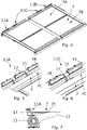
- the transport container 1 shows a cuboid transport container 1, which can be designed as a vehicle body of a truck (not shown).
- the transport container 1 has a frame structure 2 on which two opposite, vertical side surfaces 3 are formed, which in the illustration shown have side openings 3A into the interior of the transport container 1, which can be closed with side walls (not shown).
- the transport container 1 also has a vertical front wall 4, a vertical rear wall 5, a horizontal floor 6 and a panel-shaped roof 7, which are arranged on the frame structure 2.
- the roof 7 has a first roof part 7A and a second roof part 7B, which are connected to one another via a joint 8 at longitudinal edges facing one another.
- an opening device 9 for moving the roof 7 between a closed position, in which a roof opening 10 on the top leading into the interior of the transport container 1 is completely closed, and an open position, which completely releases the roof opening 10, in which the interior of the transport container can be opened through the Roof opening 10 can be loaded.
- a longitudinal edge 7C of the roof 7 is pivotable at an upper longitudinal edge 1A of the Transport container 1 arranged.
- a hinge 11A is provided at one end of the upper longitudinal edge 1A, a further hinge 11B at the other end of the upper longitudinal edge 1A and additional hinges 11C seen in the longitudinal direction between the hinge 11A and the further hinge 11B, which connected to the longitudinal edge 7C of the roof 7.
- the opening device 9 has a link 12 , which is pivotably connected to the roof 7 and to the frame structure 2 , and a drive 13 for pivoting the link 12 .
- a rotary shaft is provided as the drive 13 for the link 12 and extends along the upper longitudinal edge 1A of the transport container 1 in a box-shaped housing.
- the link 12, which acts on a transverse edge 7D of the first roof part 7A, can be pivoted by rotating the rotary shaft. As a result, the roof 7 is pivoted from the closed position towards the open position.
- a support element 18, for example a telescopic rod is arranged on the frame structure 2 in an articulated manner. With the aid of the support element 18, the free end of the second roof part 7B is guided opposite the joint 8 when the roof 7 is opened and closed.
- the hinge 11A has a horizontal pivot axis 14 in the direction of the upper longitudinal edge 1A of the transport container 1.
- the pivot axis 14 of the hinge 11A is arranged above an upper side 7E of the roof 7 in the closed position.
- an axis element 15, here an axis bolt is provided, which is rotatably accommodated in a holder 16.
- the hinge 11A has at least one connecting web 17 which connects the pivot axis 14 of the hinge 11A to the facing longitudinal edge 7C of the roof 7 .
- the connecting web 17 can be formed in one piece with the axle element 15 .
- the hinge 11A has two connecting webs 17 .
- the other hinge 11B is identical.
- the additional hinges 11C have exactly one connecting web 17 .
- the connecting web 17 extends obliquely downwards from the pivot axis 14 to the longitudinal edge 7C of the roof 7, preferably at an angle of 30° to 60°, for example substantially 45°, to the horizontal.
- the pivot axis 14 of the hinge 11A is offset in the horizontal direction perpendicular to the side surface 3 (ie in the transverse direction) from the side surface 3 inwards (ie towards the opposite side surface 3) such that the hinge 11A in the closed position of the roof 7 in the transverse direction is substantially does not protrude beyond the side surface 3 to the outside.
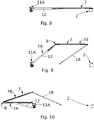
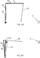
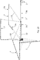
- FIGS. 8 to 13 show the individual phases when transferring the roof 7 from the closed to the open position. To close the roof 7, these steps are carried out in reverse order.
- the roof 7 In the closed position, cf. 8 , the roof 7 is arranged in a horizontal position on top of the frame structure 2.
- the roof opening 10 is closed.
- the link 12 is also in a horizontal position.
- the drive 13 for the handlebar 12 is actuated, causing the roof 7 to move into a first intermediate position, cf. 9 , is lifted.
- the second roof part 7B is pivoted with the aid of the joint 8 in relation to the first roof part 7A.
- the support member 18 supports the free end of the second roof panel 7B.
- the first roof part 7A is pivoted about the pivot axis 14 with the aid of the hinge 11A.
- the 10 shows a second intermediate position in which the link 12 is arranged substantially vertically.
- the second roof part 7B is arranged essentially at right angles to the first roof part 7A.
- FIG. 12 shows the open position, in which the first roof part 7A rests against the side surface 3 and the second roof part 7B is pivoted by approximately 180° in relation to the first roof part 7A and is arranged next to the first roof part 7A.
- side walls 3 can be arranged on the side surfaces 3 such that they can be opened or are stationary.
Landscapes
- Engineering & Computer Science (AREA)
- Mechanical Engineering (AREA)
- Chemical & Material Sciences (AREA)
- Combustion & Propulsion (AREA)
- Transportation (AREA)
- Seal Device For Vehicle (AREA)
- Fittings On The Vehicle Exterior For Carrying Loads, And Devices For Holding Or Mounting Articles (AREA)
Applications Claiming Priority (1)
| Application Number | Priority Date | Filing Date | Title |
|---|---|---|---|
| ATA50923/2020A AT523926B1 (de) | 2020-10-27 | 2020-10-27 | Transportbehälter |
Publications (1)
| Publication Number | Publication Date |
|---|---|
| EP3992005A1 true EP3992005A1 (fr) | 2022-05-04 |
Family
ID=78413739
Family Applications (1)
| Application Number | Title | Priority Date | Filing Date |
|---|---|---|---|
| EP21204892.0A Withdrawn EP3992005A1 (fr) | 2020-10-27 | 2021-10-27 | Récipient de transport |
Country Status (2)
| Country | Link |
|---|---|
| EP (1) | EP3992005A1 (fr) |
| AT (1) | AT523926B1 (fr) |
Citations (9)
| Publication number | Priority date | Publication date | Assignee | Title |
|---|---|---|---|---|
| JPS6167623A (ja) | 1984-09-10 | 1986-04-07 | Isamu Nakamura | 車両の貨物室開閉方法とその機構 |
| US4585266A (en) | 1984-03-09 | 1986-04-29 | H & S Manufacturing Co., Inc. | Manure spreader having shiftable cover |
| JPS62203818A (ja) | 1986-03-04 | 1987-09-08 | Oshima Jidosha Kogyo Kk | トラツクの幌 |
| US4767152A (en) * | 1987-04-08 | 1988-08-30 | Florig Equipment Company, Inc. | Trailer door actuating mechanism |
| JP2000225847A (ja) | 1999-02-03 | 2000-08-15 | Isamu Nakamura | 荷 室 |
| US20060208526A1 (en) * | 2005-03-18 | 2006-09-21 | Pioneer Consolidated Corp. | Covering system of a truck |
| WO2013104012A1 (fr) | 2012-01-12 | 2013-07-18 | Strasser Johann Sen | Paroi latérale pour un récipient de transport et récipient de transport |
| WO2016179680A1 (fr) * | 2015-05-14 | 2016-11-17 | Titan Trailers Inc. | Porte supérieure articulée pour une remorque |
| EP3584115A1 (fr) * | 2017-02-16 | 2019-12-25 | Hyeon Cheol Jeon | Appareil de recouvrement pour boîte de chargement de camion |
-
2020
- 2020-10-27 AT ATA50923/2020A patent/AT523926B1/de active
-
2021
- 2021-10-27 EP EP21204892.0A patent/EP3992005A1/fr not_active Withdrawn
Patent Citations (9)
| Publication number | Priority date | Publication date | Assignee | Title |
|---|---|---|---|---|
| US4585266A (en) | 1984-03-09 | 1986-04-29 | H & S Manufacturing Co., Inc. | Manure spreader having shiftable cover |
| JPS6167623A (ja) | 1984-09-10 | 1986-04-07 | Isamu Nakamura | 車両の貨物室開閉方法とその機構 |
| JPS62203818A (ja) | 1986-03-04 | 1987-09-08 | Oshima Jidosha Kogyo Kk | トラツクの幌 |
| US4767152A (en) * | 1987-04-08 | 1988-08-30 | Florig Equipment Company, Inc. | Trailer door actuating mechanism |
| JP2000225847A (ja) | 1999-02-03 | 2000-08-15 | Isamu Nakamura | 荷 室 |
| US20060208526A1 (en) * | 2005-03-18 | 2006-09-21 | Pioneer Consolidated Corp. | Covering system of a truck |
| WO2013104012A1 (fr) | 2012-01-12 | 2013-07-18 | Strasser Johann Sen | Paroi latérale pour un récipient de transport et récipient de transport |
| WO2016179680A1 (fr) * | 2015-05-14 | 2016-11-17 | Titan Trailers Inc. | Porte supérieure articulée pour une remorque |
| EP3584115A1 (fr) * | 2017-02-16 | 2019-12-25 | Hyeon Cheol Jeon | Appareil de recouvrement pour boîte de chargement de camion |
Also Published As
| Publication number | Publication date |
|---|---|
| AT523926A4 (de) | 2022-01-15 |
| AT523926B1 (de) | 2022-01-15 |
Similar Documents
| Publication | Publication Date | Title |
|---|---|---|
| DE69204556T2 (de) | Schwenkschiebevorrichtung für Fahrzeugtür. | |
| EP1314626A1 (fr) | Porte coulissante et pivotante pour véhicules, notamment porte des passagers pour véhicules de transport urbain de personnes | |
| EP3097012B1 (fr) | Dispositif d'ouverture d'une porte d'avion | |
| EP0101475B1 (fr) | Caisse, en particulier pour camion, ayant une paroi laterale rabattable | |
| EP0045009A1 (fr) | Battant d'une fenêtre, porte ou analogue pouvant se mettre, au choix, dans une position basculante ou parallèle | |
| EP1281553A1 (fr) | Bâti pour la portière de la malle arrière d'un véhicule | |
| EP2365171A2 (fr) | Palier d'un clapet sur un montage de véhicule automobile ainsi que carrosserie pour un tel véhicule automobile | |
| EP1758749B1 (fr) | Vehicule cabriolet | |
| EP2741975A1 (fr) | Conteneur de transport | |
| AT523926B1 (de) | Transportbehälter | |
| EP0531881A2 (fr) | Toit de véhicule | |
| DE202007003080U1 (de) | Führungsmechanik für einen Deckel eines Schiebehebedaches eines Fahrzeugs | |
| EP2161399A2 (fr) | Véhicule automobile doté d'un mécanisme de déplacement d'un clapet | |
| EP0074502A1 (fr) | Porte à élements | |
| DE3413506C1 (de) | Kastenaufbau,insbesondere fuer Lastfahrzeuge,mit einer aufklappbaren Seitenwand | |
| DE4427518C1 (de) | Fahrzeugaufbau, insbesondere für Lastkraftwagen und Anhänger, mit einer öffenbaren Seitenwand | |
| DE3316473C2 (de) | Öffnungs- und Schließmechanismus für ein schrägstellbares Sonnendach | |
| DE102005061978B3 (de) | Scharniervorrichtung | |
| DE4446904C1 (de) | Kraftfahrzeug-Türgriff | |
| DE2540657C2 (de) | Antriebs- und Verriegelungsvorrichtung für ein zu verschiebendes Teil, beispielsweise für eine Schiebetür | |
| DE69204915T2 (de) | Öffnungs- und Verschlussvorrichtung für Schiebehebedach, insbesondere für Kraftfahrzeug. | |
| DE8520733U1 (de) | Klappwand, insbesondere für Fahrzeugaufbauten | |
| DE8235662U1 (de) | Kastenaufbau fuer lastwagen, insbesondere lieferwagen | |
| DE2918789C2 (de) | Fensterheber | |
| AT402723B (de) | Seitenwand für den aufbau eines fahrzeuges |
Legal Events
| Date | Code | Title | Description |
|---|---|---|---|
| PUAI | Public reference made under article 153(3) epc to a published international application that has entered the european phase |
Free format text: ORIGINAL CODE: 0009012 |
|
| STAA | Information on the status of an ep patent application or granted ep patent |
Free format text: STATUS: THE APPLICATION HAS BEEN PUBLISHED |
|
| AK | Designated contracting states |
Kind code of ref document: A1 Designated state(s): AL AT BE BG CH CY CZ DE DK EE ES FI FR GB GR HR HU IE IS IT LI LT LU LV MC MK MT NL NO PL PT RO RS SE SI SK SM TR |
|
| STAA | Information on the status of an ep patent application or granted ep patent |
Free format text: STATUS: THE APPLICATION IS DEEMED TO BE WITHDRAWN |
|
| 18D | Application deemed to be withdrawn |
Effective date: 20221105 |