EP3992648B1 - Dispositif et procédé de diagnostic de batterie - Google Patents
Dispositif et procédé de diagnostic de batterie Download PDFInfo
- Publication number
- EP3992648B1 EP3992648B1 EP20902257.3A EP20902257A EP3992648B1 EP 3992648 B1 EP3992648 B1 EP 3992648B1 EP 20902257 A EP20902257 A EP 20902257A EP 3992648 B1 EP3992648 B1 EP 3992648B1
- Authority
- EP
- European Patent Office
- Prior art keywords
- voltage
- battery
- battery cell
- differential signal
- data
- Prior art date
- Legal status (The legal status is an assumption and is not a legal conclusion. Google has not performed a legal analysis and makes no representation as to the accuracy of the status listed.)
- Active
Links
Images







Classifications
-
- G—PHYSICS
- G01—MEASURING; TESTING
- G01R—MEASURING ELECTRIC VARIABLES; MEASURING MAGNETIC VARIABLES
- G01R31/00—Arrangements for testing electric properties; Arrangements for locating electric faults; Arrangements for electrical testing characterised by what is being tested not provided for elsewhere
- G01R31/36—Arrangements for testing, measuring or monitoring the electrical condition of accumulators or electric batteries, e.g. capacity or state of charge [SoC]
- G01R31/396—Acquisition or processing of data for testing or for monitoring individual cells or groups of cells within a battery
-
- G—PHYSICS
- G01—MEASURING; TESTING
- G01R—MEASURING ELECTRIC VARIABLES; MEASURING MAGNETIC VARIABLES
- G01R31/00—Arrangements for testing electric properties; Arrangements for locating electric faults; Arrangements for electrical testing characterised by what is being tested not provided for elsewhere
- G01R31/36—Arrangements for testing, measuring or monitoring the electrical condition of accumulators or electric batteries, e.g. capacity or state of charge [SoC]
- G01R31/3644—Constructional arrangements
- G01R31/3648—Constructional arrangements comprising digital calculation means, e.g. for performing an algorithm
-
- G—PHYSICS
- G01—MEASURING; TESTING
- G01R—MEASURING ELECTRIC VARIABLES; MEASURING MAGNETIC VARIABLES
- G01R31/00—Arrangements for testing electric properties; Arrangements for locating electric faults; Arrangements for electrical testing characterised by what is being tested not provided for elsewhere
- G01R31/36—Arrangements for testing, measuring or monitoring the electrical condition of accumulators or electric batteries, e.g. capacity or state of charge [SoC]
- G01R31/367—Software therefor, e.g. for battery testing using modelling or look-up tables
-
- Y—GENERAL TAGGING OF NEW TECHNOLOGICAL DEVELOPMENTS; GENERAL TAGGING OF CROSS-SECTIONAL TECHNOLOGIES SPANNING OVER SEVERAL SECTIONS OF THE IPC; TECHNICAL SUBJECTS COVERED BY FORMER USPC CROSS-REFERENCE ART COLLECTIONS [XRACs] AND DIGESTS
- Y02—TECHNOLOGIES OR APPLICATIONS FOR MITIGATION OR ADAPTATION AGAINST CLIMATE CHANGE
- Y02E—REDUCTION OF GREENHOUSE GAS [GHG] EMISSIONS, RELATED TO ENERGY GENERATION, TRANSMISSION OR DISTRIBUTION
- Y02E60/00—Enabling technologies; Technologies with a potential or indirect contribution to GHG emissions mitigation
- Y02E60/10—Energy storage using batteries
Definitions
- the present invention relates to an apparatus and method for diagnosing a battery for detecting an abnormal voltage drop phenomenon due to an internal short during charging of a battery using a differential signal.
- the secondary battery is generally used as a battery pack including a battery module in which a plurality of battery cells are connected in series and/or in parallel.
- a state and operation of the battery pack are managed and controlled by a battery management system.
- an abnormal voltage drop phenomenon due to an internal short may be observed during a charging cycle.
- a method for diagnosing such an abnormal voltage drop it is possible to detect whether or not the voltage decreases by measuring the voltage of the battery.
- a method of measuring resistance of the battery in real time is also used in order to diagnose abnormal voltage drop, but in the case of CP charging, there is a problem in that it is difficult to distinguish between a normal cell and a defective cell because variation in resistance computation increases due to a small change in current.
- US2016/187426 relates to a method for evaluating the state of charge of a battery including at least one phase of estimating the state of charge of the battery by an estimation algorithm and at least one phase of resetting of the estimation algorithm implemented during the estimation phase, which includes (i) detecting a real value of a state of charge of the battery at an instant, by (a) charging or discharging the battery, between first and second levels of state of charge; (b) measuring the voltage across the terminals of the battery during this charging or discharging; (c) evaluating the time derivative of the voltage; (d) detecting at least one particular point of this derivative corresponding to a known and predefined real value of state of charge, and (ii) resetting the estimation algorithm knowing the real value of state of charge at the given instant.
- EP3038229 relates to a storage battery that includes power storage devices in series and switching circuits each arranged between adjacent power storage devices.
- US2013/335009 relates to an inspection system (a secondary battery anomaly detection system) that has a ROM which stores data including information about a V-dQ/dV curve upon initial charge of a reference secondary battery.
- An object of the present invention is to provide an apparatus and method for diagnosing a battery capable of accurately and easily detecting an abnormal voltage drop phenomenon due to an internal short during charging of a battery using a differential signal for the voltage of the battery.
- an apparatus for diagnosing a battery according to claim 1 In a first aspect, there is provided an apparatus for diagnosing a battery according to claim 1.
- the apparatus and method for diagnosing a battery of the present invention it is possible to accurately and easily detect an abnormal voltage drop phenomenon due to an internal short during charging of the battery by using a differential signal for the voltage of the battery.
- first, second, firstly, or secondly may modify various constituent elements regardless of order and/or importance, and do not limit corresponding constituent elements.
- a first constituent element may be named as a second constituent element, and similarly, the second constituent element may also be renamed as the first constituent element.
- FIG. 1 is a block diagram illustrating a configuration of a battery control system.
- FIG. 1 a battery management system including a battery pack 1 and an upper-level controller 2 included in an upper-level system according to an embodiment of the present invention is schematically illustrated.
- the battery pack 1 includes a battery module 10 composed of one or more battery cells and capable of charging and discharging, a switching unit 14 connected in series to a positive terminal side or a negative terminal side of the battery module 10 to control a charge and discharge current flow of the battery module 10, and a battery management system 20 that monitors a voltage, current, temperature, etc. of the battery pack 1 to control and manage the battery module 10 to prevent over-charging, over-discharging, etc.
- the switching unit 14 is a semiconductor switching element for controlling a current flow for charging or discharging of the battery module 10, and, for example, at least one MOSFET may be used.
- the BMS 20 may measure or calculate a voltage and current of a gate, source, and drain of the semiconductor switching element in order to monitor the voltage, current, temperature, etc. of the battery pack 1, and may measure the current, voltage, temperature, etc. of the battery pack using a sensor 12 provided adjacent to the semiconductor switching element 14.
- the BMS 20 is an interface that receives values obtained by measuring various parameters described above, and may include a plurality of terminals and a circuit connected to these terminals to perform processing for input values.
- the BMS 20 may control ON/OFF of the switching element 14, for example, a MOSFET, and may be connected to the battery module 10 to monitor a state of the battery module 10.
- the switching element 14 for example, a MOSFET
- the upper-level controller 2 may transmit a control signal for the battery module to the BMS 20. Accordingly, an operation of the BMS 20 may be controlled based on a signal applied from the upper-level controller.
- the battery cell of the present invention may be configured to be included in a battery pack used in an energy storage system (ESS) or a vehicle, etc. However, it is not limited to these uses.
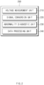
- FIG. 2 is a block diagram illustrating a configuration of an apparatus for diagnosing a battery according to an embodiment of the present invention.
- an apparatus 200 for diagnosing a battery may include a voltage measurement unit 210, a signal conversion unit 220, an abnormality diagnostic unit 230, and a data processing unit 240.
- the voltage measurement unit 210 may measure a voltage of a battery cell. In this case, the voltage measurement unit 210 may measure the voltage of the battery cell at predetermined time intervals.
- the signal conversion unit 220 may convert the voltage of the battery cell measured by the voltage measurement unit 210 into a differential signal. In this case, the signal conversion unit 220 may calculate the differential signal (e.g., dQ/dV) with respect to the capacity and voltage of the battery cell.
- the differential signal e.g., dQ/dV
- the signal conversion unit 220 may calculate a statistical value for the converted differential signal.
- the statistical value of the differential signal calculated by the signal conversion unit 220 is to determine an abnormal behavior of the battery using a sliding window (or moving window) scheme as described later.
- the statistical value for the differential signal may include standard deviation.
- the abnormality diagnostic unit 230 may diagnose an abnormality of the battery cell based on the differential signal converted by the signal conversion unit 220. Specifically, the abnormality diagnostic unit 230 may diagnose that the abnormal voltage drop has occurred in the battery cell when the statistical value of the differential signal of the battery voltage is equal to or greater than a preset reference value.
- the abnormality diagnostic unit 230 may diagnose the abnormality of the battery cell using the sliding window (or moving window) scheme with respect to the statistical value of the differential signal for the battery voltage.
- the size of the window may be arbitrarily set by the user.
- the statistical value of the differential signal of the battery voltage may include the standard deviation.
- the data processing unit 240 may convert the voltage of the battery cell to be differentiable in a predetermined section by pre-processing voltage data of the battery cell. That is, as will be described later, a case in which differential analysis is not possible may occur for generally measured voltage data of the battery due to a redundant signal and a discontinuous section. Accordingly, the data processing unit 240 may convert the voltage of the battery cell to be differential in the predetermined section by preprocessing the voltage data of the battery cell before converting the differential signal.
- the data processing unit 240 may convert the voltage of the battery cell into data in a monotonically increasing or monotonically decreasing form through sampling of the voltage data. For example, the data processing unit 240 may perform sampling on the voltage by classifying capacity values Q of the battery cells having the same voltage magnitude V and calculating an average value of the capacity values of the battery cells for each voltage magnitude. This will be described later in FIG. 4 .
- the data processing unit 240 may convert the voltage of the battery cell to satisfy continuity between adjacent data through a smoothing spline. Through this, a curve of the slope of the voltage data of the battery cell may be converted into a gentle shape.
- the apparatus for diagnosing the battery 200 may further include a memory unit and an alarm unit.
- the memory unit may store the voltage of the battery cell measured by the voltage measurement unit 210, a differential signal of the voltage calculated by the signal conversion unit 220, etc.
- the memory unit 240 may be included in the apparatus 20 for diagnosing the battery, and may be included in an external server (not illustrated) to transmit and receive data to and from the apparatus 20 for diagnosing the battery through a separate communication module.
- the alarm unit 250 may generate a warning alarm when it is determined by the diagnostic unit 230 that an abnormality has occurred in the battery cell.
- the warning alarm may be provided in the form of a message on a display unit (not illustrated), or may be provided as light or sound signals.
- the apparatus for diagnosing the battery according to the embodiment of the present invention, it is possible to accurately and easily detect the abnormal voltage drop phenomenon due to the internal short during charging of the battery by using the differential signal for the voltage of the battery.
- FIG. 3A is a graph illustrating raw data of the measured voltage of the battery
- FIG. 3B is a graph illustrating the differential signal of the voltage raw data of FIG. 3A
- the horizontal axis of FIG. 3A represents capacity (Ah) of the battery
- the vertical axis represents measured voltage (V) of the battery
- the horizontal axis of FIG. 3B represents voltage (V) of the battery
- the vertical axis represents the differential signal (dQ/dV) for the capacity and voltage of the battery.
- noise or a redundant voltage signal due to an error of the voltage sensor itself may appear in the measured voltage data of the battery. Accordingly, as illustrated in FIG. 3B , it may be difficult to analyze the differential signal for voltage or current data.
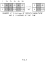
- FIG. 4 is a diagram illustrating a method of performing sampling in order to remove redundant signals of battery voltage data.
- FIG. 4 measurement data of the capacity and voltage of the battery for respective times are illustrated.
- the voltage is the same as 3.23V in sections where the battery capacities are 43Ah, 44Ah, and 46Ah, and the voltage is the same as 3.24V in sections where the battery capacities are 45Ah and 47Ah. Accordingly, as illustrated in FIGS. 3A and 3B , the redundant signals of voltage data may occur, which makes differential analysis impossible.
- the battery voltage data may be sampled by classifying the capacity values of the battery with the voltage of a specific magnitude as a reference with respect to the capacity and voltage data of the battery and computing an average value of the capacity values.
- the average value of the capacity values corresponding to each voltage may be computed with the battery voltages of 3.23V and 3.24V, which are overlapping battery voltages, as the reference.
- the capacity value when the voltage is 3.23V, 44.3Ah, which is the average value of the battery capacities of 43Ah, 44Ah, and 46Ah, may be determined as the capacity value, and when the voltage is 3.24V, 46Ah, which is the average value of the battery capacities of 45Ah and 47Ah, may be determined as the capacity value.
- voltage data may be converted into a monotonically increasing (or monotonically decreasing) form with the measured voltage as a reference.
- FIG. 5A is a graph illustrating a result obtained by performing pre-processing on battery voltage data through sampling and a smoothing spline
- FIG. 5B is a graph illustrating a differential profile for each step of preprocessing of the battery voltage data.
- the horizontal axis of FIG. 5A represents capacity (Ah) of the battery
- the vertical axis represents measured voltage (V) of the battery.
- the horizontal axis of FIG. 5B represents voltage (V) of the battery
- the vertical axis represents the differential signal (Ah/V) for the capacity and voltage of the battery.
- the voltage data may be converted so that the slope of the voltage data of the battery satisfies continuity.
- the slope of the sampled voltage data may be prevented from rapidly changing and converted into a continuous curve.
- the larger the X value the gentler the curve becomes.
- the ⁇ values may be 0.001(V) and 0.01(Q), respectively.
- the data may be converted so as to be differentiable by performing preprocessing through the method described above before detecting the abnormal voltage drop using the differential signal of the battery voltage.
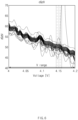
- FIG. 6 is a graph illustrating an unstable behavior due to an abnormal voltage drop through a differential signal with respect to a battery voltage.
- the horizontal axis of FIG. 6 represents the voltage of the battery
- the vertical axis represents the differential signal.
- a differential signal is illustrated for a region where the voltage of the battery cell is 4V to 4.2V, and as described above, this is because it is possible to detect the unstable voltage profile due to the internal short of the battery in a high voltage region where the voltage of the battery cell is 4V to 4.2V and exclude the influence of differential peak change caused by other factors such as deviation or deterioration between battery cells.
- FIG. 6 schematically illustrates a change in the differential signal according to each charging cycle. As illustrated in Fig. 6 , it may be seen that a section in which the differential signal is unstable (the part 4.18V of Fig. 6 ) appears in a specific charging cycle.
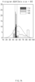
- FIG. 7A illustrates a histogram of a differential signal for each charging cycle of a battery
- FIG. 7B is a graph illustrating standard deviation for each charging cycle of the battery.
- the horizontal axis of FIG. 7A represents bins of the differential signal values
- the vertical axis represents the number of differential signal values.
- the horizontal axis of FIG. 7B represents the voltage (V)
- the vertical axis represents the standard deviation of the differential signal.
- FIG. 7A a histogram of the differential signals for the case where the charging cycles are 113, 135, and 140, respectively, is illustrated. As illustrated in FIG. 7A , it may be seen that when the charging cycle is 113, a profile of a normal charging state appears, but when the charging cycles are 135 and 140, an unstable profile appears.
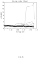
- FIG. 8 is a graph illustrating diagnosis of an abnormality in a battery through a standard deviation of the differential signal in the apparatus for diagnosing a battery according to the embodiment of the present invention.
- FIG. 8 illustrates the result derived by setting the size of the moving (sliding) window to 10, and the horizontal axis represents the voltage (V), and the vertical axis represents the standard deviation of the differential signal.
- the apparatus for diagnosing the battery may diagnose an abnormal voltage drop due to the internal short of the battery based on whether or not the standard deviation of the differential signal is equal to or greater than a preset reference value. For example, referring to FIG. 8 , it may be determined that the abnormal voltage drop has occurred in a region in which the battery voltage is 4.16V to 4.18V.
- FIG. 9 is a flowchart illustrating a method for diagnosing a battery according to an embodiment of the present invention.
- a voltage of a battery cell is measured (S910).
- the voltage of the battery cell may be measured at predetermined time intervals.
- the measured voltage of the battery cell is converted into a differential signal (S920).
- the differential signal may be calculated with respect to the capacity and voltage of the battery as described above.
- a standard deviation is calculated for the converted differential signal (S930). The standard deviation of the differential signal may be calculated for each charging cycle.
- abnormality diagnosis according to the standard deviation of the differential signal may be performed in a sliding (moving) window scheme, and the size of the window may be arbitrarily set by the user.
- the process returns to step S910.
- the standard deviation of the differential signal is equal to or greater than the preset reference value (YES)
- the abnormality of the battery cell was determined through the standard deviation of the differential signal, but various types of statistical values may be used in addition to the standard deviation.
- the method for diagnosing the battery according to the embodiment of the present invention, it is possible to accurately and easily detect the abnormal voltage drop phenomenon due to then internal short during charging of the battery by using the differential signal for the voltage of the battery.
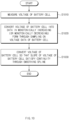
- FIG. 10 is a flowchart illustrating a method of preprocessing data in the method for diagnosing the battery according to the embodiment of the present invention.
- the voltage of the battery cell is measured (S1010). Then, the voltage of the battery cell is converted into data in a monotonically increasing (or monotonically decreasing) form through sampling of the measured voltage data (S1020). Next, the voltage of the battery cell is converted so that the slope of the voltage of the battery cell satisfies continuity through a smoothing spline (S1030). Since detailed contents of the method of preprocessing data according to FIG. 10 have been described above, detailed descriptions thereof are omitted.
- the differential analysis is performed by converting the voltage data in which noise, redundant signals, discontinuous sections, etc. exist to be differentiable in a predetermined section.
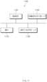
- FIG. 11 is a diagram illustrating a hardware configuration of the apparatus for diagnosing the battery according to the embodiment of the present invention.
- an apparatus 1100 for diagnosing a battery may include a microcontroller (MCU) 1110 that controls various processes and configurations, a memory 1120 in which an operating system program and various programs (e.g., a battery diagnostic program, a differential signal calculation program, etc.) are recorded, an input/output interface 1130 that provides an input interface and an output interface between the battery cell module and/or the semiconductor switching element, and a communication interface 1140 capable of communicating with the outside through a wired or wireless communication network.
- the computer program according to the present invention may be implemented as, for example, a module that performs each functional block illustrated in FIG. 2 by being recorded in the memory 1120 and processed by the microcontroller 1110.
Landscapes
- Physics & Mathematics (AREA)
- General Physics & Mathematics (AREA)
- Secondary Cells (AREA)
- Charge And Discharge Circuits For Batteries Or The Like (AREA)
- Tests Of Electric Status Of Batteries (AREA)
Claims (9)
- Appareil (200) de diagnostic d'une batterie, l'appareil (200) comprenant :une unité de mesure de tension (210) qui mesure une tension d'une cellule de batterie ; une unité de conversion de signal (220) qui convertit la tension de la cellule de batterie mesurée par l'unité de mesure de tension (210) en un signal différentiel ; et calcule un écart-type pour le signal différentiel ; etune unité de diagnostic d'anomalie (230) qui diagnostique une anomalie de la cellule de batterie sur la base du signal différentiel,caractérisé en ce quel'unité de diagnostic d'anomalie (230) diagnostique qu'une anomalie de la cellule de batterie s'est produite lorsque l'écart-type du signal différentiel est supérieur ou égal à une valeur de référence prédéfinie en utilisant un schéma de fenêtre glissante par rapport à l'écart-type.
- Appareil (200) selon la revendication 1,
dans lequel l'unité de conversion de signal (220) calcule le signal différentiel par rapport à la capacité et à la tension de la cellule de batterie. - Appareil (200) selon la revendication 1,
dans lequel l'unité de conversion de signal (220) convertit la tension de la cellule de batterie en signal différentiel pour une région dans laquelle la tension de la cellule de batterie est de 4 V à 4,2 V. - Appareil (200) selon la revendication 1, comprenant en outre :
une unité de traitement de données (240) qui convertit la tension de la cellule de batterie pour qu'elle soit différentiable dans une section prédéfinie en prétraitant les données de tension de la cellule de batterie. - Appareil (200) selon la revendication 4,
dans lequel l'unité de traitement de données (240) convertit la tension de la cellule de batterie en données sous une forme monotone croissante ou monotone décroissante par échantillonnage des données de tension. - Appareil (200) selon la revendication 5,
dans lequel l'unité de traitement de données (240) effectue un échantillonnage sur la tension en classant les valeurs de capacité des cellules de batterie ayant la même grandeur de tension et en calculant une valeur moyenne des valeurs de capacité des cellules de batterie pour chaque grandeur de tension. - Appareil (200) selon la revendication 4,
dans lequel l'unité de traitement de données (240) convertit la tension de la cellule de batterie de telle sorte qu'une pente de la tension de la cellule de batterie satisfasse à une continuité par une spline de lissage. - Procédé de diagnostic d'une batterie, le procédé comprenant :la mesure (S910) d'une tension d'une cellule de batterie ;la conversion (S920) de la tension mesurée de la cellule de batterie en un signal différentiel ;le calcul (S930) d'un écart-type pour le signal différentiel ; etle diagnostic (S940) d'une anomalie de la cellule de la batterie sur la base du signal différentiel,caractérisé en ce quele diagnostic qu'une anomalie de la cellule de batterie s'est produite est effectué lorsque l'écart-type du signal différentiel est supérieur ou égal à une valeur de référence prédéfinie en utilisant un schéma de fenêtre glissante par rapport à l'écart-type.
- Procédé selon la revendication 8, comprenant en outre :
la conversion de la tension de la cellule de batterie pour qu'elle soit différentiable dans une section prédéfinie en prétraitant les données de tension de la cellule de batterie.
Applications Claiming Priority (2)
| Application Number | Priority Date | Filing Date | Title |
|---|---|---|---|
| KR1020190172451A KR102943878B1 (ko) | 2019-12-20 | 2019-12-20 | 배터리 진단 장치 및 방법 |
| PCT/KR2020/017931 WO2021125676A1 (fr) | 2019-12-20 | 2020-12-09 | Dispositif et procédé de diagnostic de batterie |
Publications (3)
| Publication Number | Publication Date |
|---|---|
| EP3992648A1 EP3992648A1 (fr) | 2022-05-04 |
| EP3992648A4 EP3992648A4 (fr) | 2022-10-05 |
| EP3992648B1 true EP3992648B1 (fr) | 2025-01-29 |
Family
ID=76477753
Family Applications (1)
| Application Number | Title | Priority Date | Filing Date |
|---|---|---|---|
| EP20902257.3A Active EP3992648B1 (fr) | 2019-12-20 | 2020-12-09 | Dispositif et procédé de diagnostic de batterie |
Country Status (7)
| Country | Link |
|---|---|
| US (1) | US12044747B2 (fr) |
| EP (1) | EP3992648B1 (fr) |
| JP (1) | JP7384529B2 (fr) |
| KR (1) | KR102943878B1 (fr) |
| ES (1) | ES3013296T3 (fr) |
| HU (1) | HUE070292T2 (fr) |
| WO (1) | WO2021125676A1 (fr) |
Families Citing this family (15)
| Publication number | Priority date | Publication date | Assignee | Title |
|---|---|---|---|---|
| CN113866669B (zh) | 2020-06-30 | 2023-09-15 | 宁德时代新能源科技股份有限公司 | 电芯内部短路故障的检测方法、装置、设备和介质 |
| KR102849365B1 (ko) * | 2020-08-10 | 2025-08-25 | 주식회사 엘지에너지솔루션 | 배터리 이상 진단 장치 및 방법 |
| KR102889693B1 (ko) * | 2021-09-08 | 2025-11-20 | 주식회사 엘지에너지솔루션 | 배터리 진단 장치, 배터리 관리 시스템, 배터리 팩, 전기 차량 및 배터리 진단 방법 |
| CN116068441B (zh) * | 2021-10-29 | 2024-11-05 | 北汽福田汽车股份有限公司 | 动力电池内短路预警方法、装置及车辆 |
| KR102746845B1 (ko) * | 2021-11-19 | 2024-12-26 | 주식회사 원익피앤이 | 배터리 셀들의 결함을 판단하기 위한 장치 |
| CN114152826B (zh) * | 2021-11-19 | 2022-11-18 | 北京理工大学 | 一种锂离子电池单体内短路检测方法 |
| KR20230096736A (ko) * | 2021-12-23 | 2023-06-30 | 주식회사 엘지에너지솔루션 | 배터리 관리 장치 및 이의 동작 방법 |
| KR102933966B1 (ko) * | 2023-07-25 | 2026-03-04 | 주식회사 엘지에너지솔루션 | 배터리 진단 장치 및 그것의 동작 방법 |
| KR20250015476A (ko) * | 2023-07-25 | 2025-02-03 | 주식회사 엘지에너지솔루션 | 배터리 진단 장치, 배터리 진단 방법 및 배터리 진단 시스템 |
| KR20250150954A (ko) * | 2024-04-12 | 2025-10-21 | 주식회사 엘지에너지솔루션 | 데이터 분석 장치 및 방법 |
| WO2025244458A1 (fr) * | 2024-05-23 | 2025-11-27 | 주식회사 엘지에너지솔루션 | Dispositif et procédé de diagnostic de batterie |
| WO2025244457A1 (fr) * | 2024-05-23 | 2025-11-27 | 주식회사 엘지에너지솔루션 | Dispositif et procédé de diagnostic de batterie |
| WO2025244456A1 (fr) * | 2024-05-23 | 2025-11-27 | 주식회사 엘지에너지솔루션 | Dispositif et procédé de diagnostic de batterie |
| KR20260050677A (ko) * | 2024-10-08 | 2026-04-15 | 주식회사 엘지에너지솔루션 | 전자 장치, 기록매체, 및 배터리 셀의 이상을 진단하는 방법 |
| CN119414079B (zh) * | 2025-01-06 | 2025-04-01 | 奇鲸信息科技(上海)有限公司 | Cp电压检测方法、装置、电子设备及存储介质 |
Family Cites Families (16)
| Publication number | Priority date | Publication date | Assignee | Title |
|---|---|---|---|---|
| JP2013254664A (ja) | 2012-06-07 | 2013-12-19 | Hitachi Vehicle Energy Ltd | 二次電池の制御装置 |
| JP5662968B2 (ja) * | 2012-06-19 | 2015-02-04 | 株式会社日立製作所 | 二次電池の検査システム、充放電機、及び検査方法 |
| FR3007531B1 (fr) * | 2013-06-25 | 2016-12-30 | Commissariat Energie Atomique | Procede d'evaluation de l'etat de charge d'une batterie |
| WO2015179629A1 (fr) | 2014-05-22 | 2015-11-26 | Navitas Solutions, Inc. | Procédé et appareil de détection de batterie |
| JP6295858B2 (ja) | 2014-07-02 | 2018-03-20 | 日産自動車株式会社 | バッテリ管理装置 |
| JP2016126894A (ja) * | 2014-12-26 | 2016-07-11 | 株式会社東芝 | 蓄電池、蓄電池評価装置および蓄電池評価方法 |
| US20170057372A1 (en) | 2015-08-25 | 2017-03-02 | Ford Global Technologies, Llc | Electric or hybrid vehicle battery pack voltage measurement |
| JP2017133870A (ja) | 2016-01-26 | 2017-08-03 | トヨタ自動車株式会社 | リチウムイオン二次電池の異常劣化検知装置および異常劣化検知方法 |
| JP7004650B2 (ja) * | 2016-07-12 | 2022-01-21 | 株式会社エンビジョンAescジャパン | 情報処理装置、制御方法、及びプログラム |
| WO2018043222A1 (fr) * | 2016-08-30 | 2018-03-08 | パナソニックIpマネジメント株式会社 | Dispositif de gestion et système de stockage d'énergie |
| CN109642930A (zh) | 2016-09-13 | 2019-04-16 | 松下知识产权经营株式会社 | 管理装置以及蓄电系统 |
| KR102805832B1 (ko) * | 2017-01-18 | 2025-05-12 | 삼성전자주식회사 | 배터리 관리 방법 및 장치 |
| KR101969758B1 (ko) | 2017-09-14 | 2019-04-17 | 한국도로공사 | 도로의 손상을 탐지하는 단말 및 이를 적용한 도로 손상 탐지 시스템 |
| US10809307B2 (en) * | 2017-09-26 | 2020-10-20 | E-Xteq Europe | Differential battery testers |
| JP6301048B1 (ja) | 2017-10-05 | 2018-03-28 | 三菱電機株式会社 | 組電池の管理装置および組電池システム |
| JP2019113414A (ja) | 2017-12-22 | 2019-07-11 | 三菱自動車工業株式会社 | 二次電池の劣化度合測定装置 |
-
2019
- 2019-12-20 KR KR1020190172451A patent/KR102943878B1/ko active Active
-
2020
- 2020-12-09 EP EP20902257.3A patent/EP3992648B1/fr active Active
- 2020-12-09 ES ES20902257T patent/ES3013296T3/es active Active
- 2020-12-09 JP JP2022512418A patent/JP7384529B2/ja active Active
- 2020-12-09 US US17/630,360 patent/US12044747B2/en active Active
- 2020-12-09 WO PCT/KR2020/017931 patent/WO2021125676A1/fr not_active Ceased
- 2020-12-09 HU HUE20902257A patent/HUE070292T2/hu unknown
Also Published As
| Publication number | Publication date |
|---|---|
| EP3992648A1 (fr) | 2022-05-04 |
| HUE070292T2 (hu) | 2025-05-28 |
| KR20210080069A (ko) | 2021-06-30 |
| US20220276319A1 (en) | 2022-09-01 |
| KR102943878B1 (ko) | 2026-03-26 |
| US12044747B2 (en) | 2024-07-23 |
| JP2022545033A (ja) | 2022-10-24 |
| JP7384529B2 (ja) | 2023-11-21 |
| WO2021125676A1 (fr) | 2021-06-24 |
| ES3013296T3 (en) | 2025-04-11 |
| EP3992648A4 (fr) | 2022-10-05 |
Similar Documents
| Publication | Publication Date | Title |
|---|---|---|
| EP3992648B1 (fr) | Dispositif et procédé de diagnostic de batterie | |
| KR102837694B1 (ko) | 배터리 진단 장치, 배터리 진단 방법, 배터리 팩 및 자동차 | |
| EP3961233B1 (fr) | Dispositif et procédé de diagnostic de cellule de batterie | |
| US11959969B2 (en) | Apparatus and method for diagnosing battery | |
| US20240393406A1 (en) | Battery Cell Diagnosing Apparatus and Method | |
| KR20210141211A (ko) | 배터리를 진단하기 위한 장치 및 그 방법 | |
| EP4484982B1 (fr) | Appareil de diagnostic de batterie, procédé de diagnostic de batterie, bloc-batterie et véhicule | |
| EP4016099B1 (fr) | Appareil et procédé de diagnostic de batterie | |
| KR20250111280A (ko) | 배터리 데이터 관리 장치 및 그것의 동작 방법 | |
| EP4435450B1 (fr) | Dispositif de gestion de batterie et son procédé de fonctionnement |
Legal Events
| Date | Code | Title | Description |
|---|---|---|---|
| STAA | Information on the status of an ep patent application or granted ep patent |
Free format text: STATUS: THE INTERNATIONAL PUBLICATION HAS BEEN MADE |
|
| PUAI | Public reference made under article 153(3) epc to a published international application that has entered the european phase |
Free format text: ORIGINAL CODE: 0009012 |
|
| STAA | Information on the status of an ep patent application or granted ep patent |
Free format text: STATUS: REQUEST FOR EXAMINATION WAS MADE |
|
| 17P | Request for examination filed |
Effective date: 20220125 |
|
| AK | Designated contracting states |
Kind code of ref document: A1 Designated state(s): AL AT BE BG CH CY CZ DE DK EE ES FI FR GB GR HR HU IE IS IT LI LT LU LV MC MK MT NL NO PL PT RO RS SE SI SK SM TR |
|
| A4 | Supplementary search report drawn up and despatched |
Effective date: 20220906 |
|
| RIC1 | Information provided on ipc code assigned before grant |
Ipc: G01R 31/36 20200101ALI20220831BHEP Ipc: G01R 31/367 20190101AFI20220831BHEP |
|
| DAV | Request for validation of the european patent (deleted) | ||
| DAX | Request for extension of the european patent (deleted) | ||
| GRAP | Despatch of communication of intention to grant a patent |
Free format text: ORIGINAL CODE: EPIDOSNIGR1 |
|
| STAA | Information on the status of an ep patent application or granted ep patent |
Free format text: STATUS: GRANT OF PATENT IS INTENDED |
|
| INTG | Intention to grant announced |
Effective date: 20240717 |
|
| P01 | Opt-out of the competence of the unified patent court (upc) registered |
Free format text: CASE NUMBER: APP_44515/2024 Effective date: 20240731 |
|
| GRAS | Grant fee paid |
Free format text: ORIGINAL CODE: EPIDOSNIGR3 |
|
| GRAA | (expected) grant |
Free format text: ORIGINAL CODE: 0009210 |
|
| STAA | Information on the status of an ep patent application or granted ep patent |
Free format text: STATUS: THE PATENT HAS BEEN GRANTED |
|
| AK | Designated contracting states |
Kind code of ref document: B1 Designated state(s): AL AT BE BG CH CY CZ DE DK EE ES FI FR GB GR HR HU IE IS IT LI LT LU LV MC MK MT NL NO PL PT RO RS SE SI SK SM TR |
|
| REG | Reference to a national code |
Ref country code: GB Ref legal event code: FG4D |
|
| REG | Reference to a national code |
Ref country code: CH Ref legal event code: EP |
|
| REG | Reference to a national code |
Ref country code: DE Ref legal event code: R096 Ref document number: 602020045660 Country of ref document: DE |
|
| REG | Reference to a national code |
Ref country code: IE Ref legal event code: FG4D |
|
| REG | Reference to a national code |
Ref country code: ES Ref legal event code: FG2A Ref document number: 3013296 Country of ref document: ES Kind code of ref document: T3 Effective date: 20250411 |
|
| REG | Reference to a national code |
Ref country code: HU Ref legal event code: AG4A Ref document number: E070292 Country of ref document: HU |
|
| REG | Reference to a national code |
Ref country code: NL Ref legal event code: MP Effective date: 20250129 |
|
| PG25 | Lapsed in a contracting state [announced via postgrant information from national office to epo] |
Ref country code: NL Free format text: LAPSE BECAUSE OF FAILURE TO SUBMIT A TRANSLATION OF THE DESCRIPTION OR TO PAY THE FEE WITHIN THE PRESCRIBED TIME-LIMIT Effective date: 20250129 |
|
| PG25 | Lapsed in a contracting state [announced via postgrant information from national office to epo] |
Ref country code: RS Free format text: LAPSE BECAUSE OF FAILURE TO SUBMIT A TRANSLATION OF THE DESCRIPTION OR TO PAY THE FEE WITHIN THE PRESCRIBED TIME-LIMIT Effective date: 20250429 |
|
| PG25 | Lapsed in a contracting state [announced via postgrant information from national office to epo] |
Ref country code: FI Free format text: LAPSE BECAUSE OF FAILURE TO SUBMIT A TRANSLATION OF THE DESCRIPTION OR TO PAY THE FEE WITHIN THE PRESCRIBED TIME-LIMIT Effective date: 20250129 |
|
| PG25 | Lapsed in a contracting state [announced via postgrant information from national office to epo] |
Ref country code: PL Free format text: LAPSE BECAUSE OF FAILURE TO SUBMIT A TRANSLATION OF THE DESCRIPTION OR TO PAY THE FEE WITHIN THE PRESCRIBED TIME-LIMIT Effective date: 20250129 |
|
| REG | Reference to a national code |
Ref country code: LT Ref legal event code: MG9D |
|
| PG25 | Lapsed in a contracting state [announced via postgrant information from national office to epo] |
Ref country code: IS Free format text: LAPSE BECAUSE OF FAILURE TO SUBMIT A TRANSLATION OF THE DESCRIPTION OR TO PAY THE FEE WITHIN THE PRESCRIBED TIME-LIMIT Effective date: 20250529 Ref country code: NO Free format text: LAPSE BECAUSE OF FAILURE TO SUBMIT A TRANSLATION OF THE DESCRIPTION OR TO PAY THE FEE WITHIN THE PRESCRIBED TIME-LIMIT Effective date: 20250429 |
|
| REG | Reference to a national code |
Ref country code: AT Ref legal event code: MK05 Ref document number: 1763959 Country of ref document: AT Kind code of ref document: T Effective date: 20250129 |
|
| PG25 | Lapsed in a contracting state [announced via postgrant information from national office to epo] |
Ref country code: HR Free format text: LAPSE BECAUSE OF FAILURE TO SUBMIT A TRANSLATION OF THE DESCRIPTION OR TO PAY THE FEE WITHIN THE PRESCRIBED TIME-LIMIT Effective date: 20250129 |
|
| PG25 | Lapsed in a contracting state [announced via postgrant information from national office to epo] |
Ref country code: LV Free format text: LAPSE BECAUSE OF FAILURE TO SUBMIT A TRANSLATION OF THE DESCRIPTION OR TO PAY THE FEE WITHIN THE PRESCRIBED TIME-LIMIT Effective date: 20250129 Ref country code: PT Free format text: LAPSE BECAUSE OF FAILURE TO SUBMIT A TRANSLATION OF THE DESCRIPTION OR TO PAY THE FEE WITHIN THE PRESCRIBED TIME-LIMIT Effective date: 20250529 |
|
| PG25 | Lapsed in a contracting state [announced via postgrant information from national office to epo] |
Ref country code: GR Free format text: LAPSE BECAUSE OF FAILURE TO SUBMIT A TRANSLATION OF THE DESCRIPTION OR TO PAY THE FEE WITHIN THE PRESCRIBED TIME-LIMIT Effective date: 20250430 Ref country code: BG Free format text: LAPSE BECAUSE OF FAILURE TO SUBMIT A TRANSLATION OF THE DESCRIPTION OR TO PAY THE FEE WITHIN THE PRESCRIBED TIME-LIMIT Effective date: 20250129 |
|
| PG25 | Lapsed in a contracting state [announced via postgrant information from national office to epo] |
Ref country code: AT Free format text: LAPSE BECAUSE OF FAILURE TO SUBMIT A TRANSLATION OF THE DESCRIPTION OR TO PAY THE FEE WITHIN THE PRESCRIBED TIME-LIMIT Effective date: 20250129 |
|
| PG25 | Lapsed in a contracting state [announced via postgrant information from national office to epo] |
Ref country code: SE Free format text: LAPSE BECAUSE OF FAILURE TO SUBMIT A TRANSLATION OF THE DESCRIPTION OR TO PAY THE FEE WITHIN THE PRESCRIBED TIME-LIMIT Effective date: 20250129 |
|
| PG25 | Lapsed in a contracting state [announced via postgrant information from national office to epo] |
Ref country code: SM Free format text: LAPSE BECAUSE OF FAILURE TO SUBMIT A TRANSLATION OF THE DESCRIPTION OR TO PAY THE FEE WITHIN THE PRESCRIBED TIME-LIMIT Effective date: 20250129 |
|
| PG25 | Lapsed in a contracting state [announced via postgrant information from national office to epo] |
Ref country code: DK Free format text: LAPSE BECAUSE OF FAILURE TO SUBMIT A TRANSLATION OF THE DESCRIPTION OR TO PAY THE FEE WITHIN THE PRESCRIBED TIME-LIMIT Effective date: 20250129 |
|
| PG25 | Lapsed in a contracting state [announced via postgrant information from national office to epo] |
Ref country code: IT Free format text: LAPSE BECAUSE OF FAILURE TO SUBMIT A TRANSLATION OF THE DESCRIPTION OR TO PAY THE FEE WITHIN THE PRESCRIBED TIME-LIMIT Effective date: 20250129 |
|
| PG25 | Lapsed in a contracting state [announced via postgrant information from national office to epo] |
Ref country code: EE Free format text: LAPSE BECAUSE OF FAILURE TO SUBMIT A TRANSLATION OF THE DESCRIPTION OR TO PAY THE FEE WITHIN THE PRESCRIBED TIME-LIMIT Effective date: 20250129 Ref country code: CZ Free format text: LAPSE BECAUSE OF FAILURE TO SUBMIT A TRANSLATION OF THE DESCRIPTION OR TO PAY THE FEE WITHIN THE PRESCRIBED TIME-LIMIT Effective date: 20250129 |
|
| PG25 | Lapsed in a contracting state [announced via postgrant information from national office to epo] |
Ref country code: RO Free format text: LAPSE BECAUSE OF FAILURE TO SUBMIT A TRANSLATION OF THE DESCRIPTION OR TO PAY THE FEE WITHIN THE PRESCRIBED TIME-LIMIT Effective date: 20250129 |
|
| PG25 | Lapsed in a contracting state [announced via postgrant information from national office to epo] |
Ref country code: SK Free format text: LAPSE BECAUSE OF FAILURE TO SUBMIT A TRANSLATION OF THE DESCRIPTION OR TO PAY THE FEE WITHIN THE PRESCRIBED TIME-LIMIT Effective date: 20250129 |
|
| REG | Reference to a national code |
Ref country code: DE Ref legal event code: R097 Ref document number: 602020045660 Country of ref document: DE |
|
| PLBE | No opposition filed within time limit |
Free format text: ORIGINAL CODE: 0009261 |
|
| STAA | Information on the status of an ep patent application or granted ep patent |
Free format text: STATUS: NO OPPOSITION FILED WITHIN TIME LIMIT |
|
| 26N | No opposition filed |
Effective date: 20251030 |
|
| PGFP | Annual fee paid to national office [announced via postgrant information from national office to epo] |
Ref country code: DE Payment date: 20251120 Year of fee payment: 6 |
|
| PGFP | Annual fee paid to national office [announced via postgrant information from national office to epo] |
Ref country code: GB Payment date: 20251120 Year of fee payment: 6 |
|
| PGFP | Annual fee paid to national office [announced via postgrant information from national office to epo] |
Ref country code: HU Payment date: 20251216 Year of fee payment: 6 Ref country code: FR Payment date: 20251125 Year of fee payment: 6 |
|
| PGFP | Annual fee paid to national office [announced via postgrant information from national office to epo] |
Ref country code: ES Payment date: 20260122 Year of fee payment: 6 |