EP3998011A1 - Extrémité portative d'endoscope - Google Patents
Extrémité portative d'endoscope Download PDFInfo
- Publication number
- EP3998011A1 EP3998011A1 EP20848946.8A EP20848946A EP3998011A1 EP 3998011 A1 EP3998011 A1 EP 3998011A1 EP 20848946 A EP20848946 A EP 20848946A EP 3998011 A1 EP3998011 A1 EP 3998011A1
- Authority
- EP
- European Patent Office
- Prior art keywords
- toggle
- positioning
- fit
- nut
- housing
- Prior art date
- Legal status (The legal status is an assumption and is not a legal conclusion. Google has not performed a legal analysis and makes no representation as to the accuracy of the status listed.)
- Granted
Links
Images


Classifications
-
- A—HUMAN NECESSITIES
- A61—MEDICAL OR VETERINARY SCIENCE; HYGIENE
- A61B—DIAGNOSIS; SURGERY; IDENTIFICATION
- A61B1/00—Instruments for performing medical examinations of the interior of cavities or tubes of the body by visual or photographical inspection, e.g. endoscopes; Illuminating arrangements therefor
- A61B1/00002—Operational features of endoscopes
- A61B1/00039—Operational features of endoscopes provided with input arrangements for the user
- A61B1/00042—Operational features of endoscopes provided with input arrangements for the user for mechanical operation
-
- A—HUMAN NECESSITIES
- A61—MEDICAL OR VETERINARY SCIENCE; HYGIENE
- A61B—DIAGNOSIS; SURGERY; IDENTIFICATION
- A61B1/00—Instruments for performing medical examinations of the interior of cavities or tubes of the body by visual or photographical inspection, e.g. endoscopes; Illuminating arrangements therefor
- A61B1/00064—Constructional details of the endoscope body
- A61B1/00066—Proximal part of endoscope body, e.g. handles
-
- A—HUMAN NECESSITIES
- A61—MEDICAL OR VETERINARY SCIENCE; HYGIENE
- A61B—DIAGNOSIS; SURGERY; IDENTIFICATION
- A61B1/00—Instruments for performing medical examinations of the interior of cavities or tubes of the body by visual or photographical inspection, e.g. endoscopes; Illuminating arrangements therefor
- A61B1/00064—Constructional details of the endoscope body
- A61B1/00105—Constructional details of the endoscope body characterised by modular construction
-
- A—HUMAN NECESSITIES
- A61—MEDICAL OR VETERINARY SCIENCE; HYGIENE
- A61B—DIAGNOSIS; SURGERY; IDENTIFICATION
- A61B1/00—Instruments for performing medical examinations of the interior of cavities or tubes of the body by visual or photographical inspection, e.g. endoscopes; Illuminating arrangements therefor
- A61B1/00112—Connection or coupling means
- A61B1/00121—Connectors, fasteners and adapters, e.g. on the endoscope handle
- A61B1/00128—Connectors, fasteners and adapters, e.g. on the endoscope handle mechanical, e.g. for tubes or pipes
-
- A—HUMAN NECESSITIES
- A61—MEDICAL OR VETERINARY SCIENCE; HYGIENE
- A61B—DIAGNOSIS; SURGERY; IDENTIFICATION
- A61B1/00—Instruments for performing medical examinations of the interior of cavities or tubes of the body by visual or photographical inspection, e.g. endoscopes; Illuminating arrangements therefor
- A61B1/00131—Accessories for endoscopes
-
- A—HUMAN NECESSITIES
- A61—MEDICAL OR VETERINARY SCIENCE; HYGIENE
- A61B—DIAGNOSIS; SURGERY; IDENTIFICATION
- A61B1/00—Instruments for performing medical examinations of the interior of cavities or tubes of the body by visual or photographical inspection, e.g. endoscopes; Illuminating arrangements therefor
- A61B1/005—Flexible endoscopes
- A61B1/0051—Flexible endoscopes with controlled bending of insertion part
- A61B1/0052—Constructional details of control elements, e.g. handles
Definitions
- the present invention relates to the technical field of endoscopes, and more particularly, to a handheld end of an endoscope.
- the medical endoscope system is composed of an endoscope and an endoscope-specific processor.
- the endoscope includes an imaging unit such as a charge coupled device (CCD) image sensor for imaging an inside of a body cavity, and a first connector provided at an end of a universal cord.
- the endoscope-specific processor includes a second connector to which the first connector of the endoscope is detachably attached, a control unit for performing image processing on image data output by the endoscope, and a light source.
- CCD charge coupled device
- the first connector of the endoscope is connected to the second connector of the endoscope-specific processor through an electrical contact, such that power is supplied from the endoscope-specific processor to the endoscope, and an image signal and a control signal are transmitted between the endoscope-specific processor and the endoscope.
- the present invention is provided in view of the problems as mentioned above and/or existing in the prior art.
- An objective of the present invention is to provide a handheld end of an endoscope.
- a handheld end of an endoscope includes a housing, an insertion end positioning assembly and a self-locking assembly, where the self-locking assembly is hinged to the housing;
- the housing includes an insertion port;
- the insertion end positioning assembly includes a positioning member, a first positioning nut and a threaded steel tube; the positioning member is inserted into the insertion port; the threaded steel tube is in threaded fit with the first positioning nut; the first positioning nut is fixed in the positioning member;
- the insertion end positioning assembly further includes a through hole and a fixing member; and the fixing member is fit with the through hole to abut against the threaded steel tube.
- the positioning member may be provided with a limiting slot; the insertion end positioning assembly may further include a stop piece; the stop piece may be provided in the limiting slot, and a diameter of the stop piece may be greater than a diameter of the insertion port.
- the fixing member may include a second nut and a fixing screw; the second nut may be fixed to the through hole; and the fixing screw may be in threaded fit with the second nut.
- the self-locking assembly may include a toggle support, an elastic support and a toggle handle; the toggle handle may be sleeved on the toggle support, and may be movable along a sleeving direction; a shaft of the toggle support may pass through the housing, and may be connected to the elastic support on the other side; an inner side of the toggle support may be provided with a toggle lever and a friction piece; one end of the toggle lever may be hinged to the toggle handle, and the other end thereof may be not connected to the friction piece; the toggle lever may have an L-shaped cross section, with a middle bend fixed to the toggle support; and the toggle lever may be hinged to the toggle support through a pin.
- the self-locking assembly may further include a limiting member; the limiting member may include a fixing disc and a fitted disc; the fixing disc and the fitted disc may be fit with each other; the fixing disc may be fixed to a long shaft; and a limiting block may be provided on the fitted disc.
- reinforcing ribs may be further provided inside the housing; there may be two reinforcing ribs; and a movement space formed between the two reinforcing ribs may be fit with the limiting block.
- one end of the toggle lever may be provided with a fitting bump, and one end of the friction piece may be provided with a fitted bump; and a plane on which the fitting bump may be located may be opposite to a plane on which the fitted bump may be located, so that the fitting bump and the fitted bump are fit with each other.
- the toggle lever and the toggle handle may be hinged through a pin; a connecting end of the toggle lever may be provided with a long oval hole; and the pin may pass through the long oval hole to be fit with the toggle support.
- one end of the friction piece may be fixed to the other end of the elastic support through the long shaft.
- one embodiment or “embodiments” herein refers to a particular feature, structure or characteristic that may be included in at least one implementation of the present invention.
- the phrase “in an embodiment” used multiple times herein refers to neither one same embodiment nor an individual or alternative embodiment mutually exclusive with other embodiment.
- the present invention provides a handheld end of an endoscope.
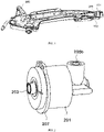
- the handheld end of the endoscope includes a housing 100, an insertion end positioning assembly 200 and a self-locking assembly 300.
- the insertion end positioning assembly 200 is fit with the housing 100 to fix an insertion end.
- the self-locking assembly 300 is hinged to the housing 100.
- the housing 100 includes an insertion port 101. When the housing 100 and the insertion end positioning assembly 200 are fit, the insertion end positioning assembly 200 is inserted into the insertion port 101.
- the insertion end positioning assembly 200 includes a positioning member 201, a first positioning nut 202, a threaded steel tube 203, a through hole 204 and a fixing member 205.
- the positioning member 201 is inserted into the insertion port 101.
- the threaded steel tube 203 is in threaded fit with the first positioning nut 202.
- the first positioning nut 202 is fixed in the positioning member 201.
- the fixing member 205 is fit with the through hole 204 to abut against the threaded steel tube 203.
- the positioning member 201 is provided with a limiting slot 201a.
- the insertion end positioning assembly 200 further includes a stop piece 207.
- the stop piece 207 is provided in the limiting slot 201a, and a diameter of the stop piece 207 is greater than a diameter of the insertion port 101. In this way, when the positioning member 201 is inserted into the insertion port 101, the stop piece 207 clamps the positioning member 201 at the insertion port 101. When the positioning member 201 is pulled, the positioning member 201 will not disengage from the insertion port 101.
- the parts are fit with each other.
- the stop piece 207 only limits the axial movement of the positioning member 201. That is, the positioning member 201 may also be rotatable.
- the fixing member 205 is fit with the through hole 204 to abut against the threaded steel tube 203, thereby limiting the rotation of the positioning member 201.
- the threaded steel tube 203 is provided with a cord connected to the endoscope.
- One end of the cord is fixed inside the housing 100, and the other end thereof passes through the threaded steel tube 203 and the insertion port 101.
- the fixing member 205 includes a second nut 205a and a fixing screw 205b.
- the second nut 205a is fixed to the through hole 204, and the fixing screw 205b is in threaded fit with the second nut 205a.
- the second nut 205a is fixedly connected to the through hole 204 by bonding or welding.
- the fixing screw 205b is rotated, the fixing screw 205b is moved relative to the second nut 205a such that an end portion of an entry end of the fixing screw 205b presses the cord.
- the working principle of this embodiment is as follows.
- the stop piece 207 clamps the positioning member 201 at the insertion port 101.
- the positioning member 201 will not disengage from the insertion port 101.
- the second nut 205a is fixedly connected to the through hole 204 by bonding or welding.
- the fixing screw 205b is rotated, the fixing screw 205b is moved relative to the second nut 205a such that an end portion of an entry end of the fixing screw 205b presses the cord.
- a second embodiment of the present invention provides a handheld end of an endoscope.
- the insertion end positioning assembly 200 further includes a locking member 206.
- An inner bottom of the locking member 206 is provided with a straight clamping slot 206a, and an inner wall of the locking member 206 is provided with an internal thread.
- a tail end of the positioning member 201 is provided with a straight fixing block 201b.
- the straight fixing block 201b is fit with the straight clamping slot 206a.
- the handheld end of the endoscope includes a housing 100, an insertion end positioning assembly 200 and a self-locking assembly 300.
- the insertion end positioning assembly 200 is fit with the housing 100 to fix an insertion end.
- the self-locking assembly 300 is hinged to the housing 100.
- the housing 100 includes an insertion port 101. When the housing 100 and the insertion end positioning assembly 200 are fit, the insertion end positioning assembly 200 is inserted into the insertion port 101.
- the insertion end positioning assembly 200 includes a positioning member 201, a first positioning nut 202, a threaded steel tube 203, a through hole 204, a fixing member 205 and a locking member 206.
- the positioning member 201 is inserted into the insertion port 101, and a straight fixing block 201b is provided at a tail end of the positioning member 201.
- the threaded steel tube 203 is in threaded fit with the first positioning nut 202.
- the first positioning nut 202 is fixed in the positioning member 201.
- the fixing member 205 is fit with the through hole 204 to abut against the threaded steel tube 203.
- An inner bottom of the locking member 206 is provided with a straight clamping slot 206a, and an inner wall of the locking member 206 is provided with an internal thread.
- the straight fixing block 201b is fit with the straight clamping slot 206a.
- the positioning member 201 is provided with a limiting slot 201a.
- the insertion end positioning assembly 200 further includes a stop piece 207.
- the stop piece 207 is provided in the limiting slot 201a, and a diameter of the stop piece 207 is greater than a diameter of the insertion port 101. In this way, when the positioning member 201 is inserted into the insertion port 101, the stop piece 207 clamps the positioning member 201 at the insertion port 101. When the positioning member 201 is pulled, the positioning member 201 will not disengage from the insertion port 101.
- the parts are fit with each other.
- the stop piece 207 only limits the axial movement of the positioning member 201. That is, the positioning member 201 may also be rotatable.
- the fixing member 205 is fit with the through hole 204 to abut against the threaded steel tube 203, thereby limiting the rotation of the positioning member 201.
- the threaded steel tube 203 is provided with a cord connected to the endoscope.
- One end of the cord is fixed inside the housing 100, and the other end thereof passes through the threaded steel tube 203 and the insertion port 101.
- the fixing member 205 includes a second nut 205a and a fixing screw 205b.
- the second nut 205a is fixed to the through hole 204, and the fixing screw 205b is in threaded fit with the second nut 205a.
- the second nut 205a is fixedly connected to the through hole 204 by bonding or welding.
- the fixing screw 205b is rotated, the fixing screw 205b is moved relative to the second nut 205a such that an end portion of an entry end of the fixing screw 205b presses the cord.
- the housing 100 further includes a protective shell 102.
- the protective shell 102 is provided outside the insertion port 101, and is fixedly connected to the insertion port 101.
- the protective shell 102 is provided with an external thread, and the external thread is fit with the internal thread.
- the external thread of the protective shell 102 is fit with the internal thread of the locking member 206 to lock the position of a plug-in end.
- the working principle of this embodiment is as follows.
- the stop piece 207 clamps the positioning member 201 at the insertion port 101.
- the positioning member 201 will not disengage from the insertion port 101.
- the second nut 205a is fixedly connected to the through hole 204 by bonding or welding.
- the fixing screw 205b is rotated, the fixing screw 205b is moved relative to the second nut 205a such that an end portion of an entry end of the fixing screw 205b presses the cord.
- the straight fixing block 201b is fit with the straight clamping slot 206a, and the external thread of the protective shell 102 is fit with the internal thread of the locking member 206, so as to position the locking member 206 and lock the position of the plug-in end.
- a third embodiment of the present invention provides a handheld end of an endoscope.
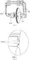
- the self-locking assembly 300 includes a toggle support 301, an elastic support 302 and a toggle handle 303.
- the toggle handle 303 is sleeved on the toggle support 301, and is movable along a sleeving direction.
- a shaft of the toggle support 301 passes through the housing 100, and is connected to the elastic support 302 on the other side.
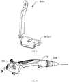
- An inner side of the toggle support 301 is provided with a toggle lever 301a and a friction piece 301b.
- the toggle lever 301a One end of the toggle lever 301a is hinged to the toggle handle 303, and the other end thereof is not connected to the friction piece 301b.
- the toggle lever 301a has an L-shaped cross section, with a middle bend fixed to the toggle support 301.
- the toggle lever 301a is hinged to the toggle support 301 through a pin.
- the self-locking assembly 300 includes a toggle support 301, an elastic support 302 and a toggle handle 303.
- the toggle handle 303 is sleeved on the toggle support 301, and is movable along a sleeving direction.
- a shaft of the toggle support 301 passes through the housing 100, and is connected to the elastic support 302 on the other side. That is to say, the toggle handle 303 is sleeved on the toggle support 301, and it is movable left and right along the toggle support 301.
- the toggle support 301 is provided with a toggle lever 301a and a friction piece 301b.
- the toggle lever 301a has an L-shaped cross section, with a middle bend fixed to the toggle support 301.
- the toggle lever 301a is hinged to the toggle support 301 through a pin. When the toggle lever 301a is stressed, it is rotatable around the pin, so as to push the friction piece 301b to move.
- toggle lever 301a and the toggle handle 303 are hinged through the pin, a connecting end of the toggle lever 301a is provided with a long oval hole, and the toggle handle 303 passes through the long oval hole to be fit with the toggle support 301. Therefore, when the toggle handle 303 moves on the toggle support 301, the toggle lever 301a provided with the long oval hole is movable up and down and left and right around the pin. The left-right direction is perpendicular to the toggle support 301.
- one end of the toggle lever 301a is provided with a fitting bump 301a-1
- one end of the friction piece 301b is provided with a fitted bump 301b-1.
- a plane on which the fitting bump 301a-1 is located is opposite to a plane on which the fitted bump 301b-1 is located, so that the fitting bump and the fitted bump are fit with each other.
- the fitting bump 301a-1 and the fitted bump 301b-1 each have smooth curved surfaces.
- the fitting bump 301a-1 and the fitted bump 301b-1 each have semicircular cross sections.
- the fitting bump 301a-1 and the fitted bump 301b-1 are each the same in number.
- a self-locking principle of the handheld end of an endoscope is as follows.
- the toggle handle 303 is placed on a left side of the toggle support 301.
- the toggle handle 303 is manually toggled to move from the left side of the toggle support 301 to a right side of the toggle support 301, and it stays at the right side of the toggle support 301.
- the toggle handle 303 moves from the left side of the toggle support 301 to the right side of the toggle support 301, one end of the long oval hole of the toggle lever 301a moves relative to the pin, so that the toggle lever 301a rotates around the pin.
- the fitting bump 301a-1 is placed under the fitted bump 301b-1.
- the fitting bump 301a-1 is placed above the fitted bump 301b-1.
- one end of the friction piece 301b is fixed to the other end of the elastic support 302 through a long shaft 401.
- the elastic support 302 is in contact with the housing 100, so the resistance of pulling a tail end of a cord through the self-locking assembly 300 is very large.
- the tail end of the cord is self-locking without external force, and it is difficult to be pulled by the self-locking assembly 300.
- the fitting bump 301a-1 moves from below the fitted bump 301b-1 to above the fitted bump 301b-1
- the friction piece 301b pushes the long shaft 401 such that the elastic support 302 does not contact the housing 100. In this way, the resistance of pulling the tail end of the cord through the self-locking assembly 300 is reduced, such that the tail end of the cord can move freely through the self-locking assembly 300.
- the self-locking assembly 300 further includes a limiting member 304.
- the limiting member 304 includes a fixing disc 304a and a fitted disc 304b.
- the fixing disc 304a and the fitted disc 304b are fit with each other, and the fixing disc 304a is fixed to the long shaft 401.
- a limiting block 304b-1 is provided on the fitted disc 304b.
- reinforcing ribs 103 are further provided inside the housing 100. There are two reinforcing ribs 103. Amovement space formed between the two reinforcing ribs 103 is fit with the limiting block 304b-1, such that the movement of the limiting block 304b-1 is limited, thereby realizing the control of the toggle range of the self-locking assembly 300.
Landscapes
- Health & Medical Sciences (AREA)
- Life Sciences & Earth Sciences (AREA)
- Surgery (AREA)
- Engineering & Computer Science (AREA)
- Biomedical Technology (AREA)
- Molecular Biology (AREA)
- Pathology (AREA)
- Radiology & Medical Imaging (AREA)
- Nuclear Medicine, Radiotherapy & Molecular Imaging (AREA)
- Biophysics (AREA)
- Physics & Mathematics (AREA)
- Heart & Thoracic Surgery (AREA)
- Medical Informatics (AREA)
- Optics & Photonics (AREA)
- Animal Behavior & Ethology (AREA)
- General Health & Medical Sciences (AREA)
- Public Health (AREA)
- Veterinary Medicine (AREA)
- Mechanical Engineering (AREA)
- Endoscopes (AREA)
- Instruments For Viewing The Inside Of Hollow Bodies (AREA)
Applications Claiming Priority (2)
| Application Number | Priority Date | Filing Date | Title |
|---|---|---|---|
| CN201910725815.9A CN110367907B (zh) | 2019-08-07 | 2019-08-07 | 一种内窥镜的手持端 |
| PCT/CN2020/089654 WO2021022858A1 (fr) | 2019-08-07 | 2020-05-11 | Extrémité portative d'endoscope |
Publications (3)
| Publication Number | Publication Date |
|---|---|
| EP3998011A1 true EP3998011A1 (fr) | 2022-05-18 |
| EP3998011A4 EP3998011A4 (fr) | 2022-09-07 |
| EP3998011B1 EP3998011B1 (fr) | 2023-03-15 |
Family
ID=68258310
Family Applications (1)
| Application Number | Title | Priority Date | Filing Date |
|---|---|---|---|
| EP20848946.8A Active EP3998011B1 (fr) | 2019-08-07 | 2020-05-11 | Extrémité portative d'endoscope |
Country Status (6)
| Country | Link |
|---|---|
| US (1) | US11980337B2 (fr) |
| EP (1) | EP3998011B1 (fr) |
| JP (1) | JP7175067B2 (fr) |
| CN (1) | CN110367907B (fr) |
| ES (1) | ES2942690T3 (fr) |
| WO (1) | WO2021022858A1 (fr) |
Families Citing this family (7)
| Publication number | Priority date | Publication date | Assignee | Title |
|---|---|---|---|---|
| CN110432853B (zh) * | 2019-08-07 | 2024-03-19 | 湖南省华芯医疗器械有限公司 | 一种内窥镜的自锁装置 |
| CN110367907B (zh) * | 2019-08-07 | 2024-04-12 | 湖南省华芯医疗器械有限公司 | 一种内窥镜的手持端 |
| CN110897591B (zh) * | 2019-12-31 | 2025-01-07 | 湖南省华芯医疗器械有限公司 | 一种多向导向的内窥镜 |
| CN111202488B (zh) * | 2020-03-12 | 2025-01-07 | 湖南省华芯医疗器械有限公司 | 一种适用于内窥镜的自锁装置 |
| CN115460963A (zh) * | 2020-04-24 | 2022-12-09 | 安布股份有限公司 | 用于内窥镜的手柄 |
| CN114869201B (zh) * | 2022-05-25 | 2023-04-18 | 湖南省华芯医疗器械有限公司 | 一种内窥镜手柄的重复使用段、内窥镜手柄及内窥镜 |
| CN116831499B (zh) * | 2023-07-10 | 2024-05-28 | 湖南中聚内窥镜有限公司 | 一种电子式内窥镜 |
Family Cites Families (38)
| Publication number | Priority date | Publication date | Assignee | Title |
|---|---|---|---|---|
| JPH0642865B2 (ja) | 1986-01-17 | 1994-06-08 | オリンパス光学工業株式会社 | 内視鏡 |
| JPS6335226A (ja) | 1986-07-30 | 1988-02-15 | オリンパス光学工業株式会社 | 内視鏡 |
| US4750477A (en) * | 1987-02-20 | 1988-06-14 | Circon Corporation | Instrument control head |
| DE3729131C1 (de) * | 1987-09-01 | 1989-03-30 | Wolf Gmbh Richard | Steuervorrichtung zum Ablenken des distalen Endes eines Endoskopes |
| US6132390A (en) * | 1996-02-28 | 2000-10-17 | Eupalamus Llc | Handle for manipulation of a stylet used for deflecting a tip of a lead or catheter |
| JP3776501B2 (ja) | 1996-04-09 | 2006-05-17 | オリンパス株式会社 | 内視鏡の湾曲操作装置 |
| JP4155072B2 (ja) | 2003-03-26 | 2008-09-24 | フジノン株式会社 | 内視鏡 |
| JP5047689B2 (ja) * | 2007-05-17 | 2012-10-10 | オリンパスメディカルシステムズ株式会社 | 電動湾曲内視鏡 |
| JP5137477B2 (ja) * | 2007-06-22 | 2013-02-06 | Hoya株式会社 | 内視鏡における連結部の構造 |
| JP2009106697A (ja) * | 2007-11-01 | 2009-05-21 | Olympus Corp | 内視鏡装置 |
| US8366604B2 (en) | 2009-06-03 | 2013-02-05 | Gyrus Acmi Inc. | Endoscope combined deflection control and lock |
| JP2011177383A (ja) | 2010-03-02 | 2011-09-15 | Fujifilm Corp | 内視鏡の操作ワイヤ連結装置及び内視鏡 |
| JP5457318B2 (ja) | 2010-09-24 | 2014-04-02 | 富士フイルム株式会社 | 内視鏡 |
| EP2821000A4 (fr) * | 2012-02-27 | 2015-11-11 | Olympus Corp | Dispositif d'insertion comprenant une unité d'entrée de fonctionnement |
| JP2013202214A (ja) | 2012-03-28 | 2013-10-07 | Olympus Corp | 内視鏡の操作ワイヤ接続構造 |
| JP2015089383A (ja) * | 2013-11-05 | 2015-05-11 | セイコーエプソン株式会社 | 超音波プローブおよび超音波計測装置 |
| CN105246392B (zh) | 2013-12-24 | 2017-09-19 | 奥林巴斯株式会社 | 内窥镜用护套 |
| CN103654693B (zh) * | 2013-12-25 | 2016-08-17 | 武汉佑康科技有限公司 | 用于内窥镜的改进型角度调整机构 |
| CN203988246U (zh) | 2014-08-14 | 2014-12-10 | 武汉半边天医疗技术发展有限公司 | 一种可拆装的超声刀管快速对接装置 |
| WO2016035672A1 (fr) | 2014-09-05 | 2016-03-10 | オリンパス株式会社 | Endoscope |
| CN104586346B (zh) * | 2015-01-20 | 2016-06-29 | 山东省肿瘤医院 | 纤维支气管镜 |
| JP6447894B2 (ja) * | 2015-06-02 | 2019-01-09 | 武漢佑康科技有限公司 | 内視鏡用自動ロック式角度調整機構 |
| WO2017188044A1 (fr) * | 2016-04-25 | 2017-11-02 | オリンパス株式会社 | Dispositif de retraitement d'endoscope |
| JP6467061B2 (ja) * | 2016-07-11 | 2019-02-06 | Hoya株式会社 | 内視鏡 |
| CN107485360B (zh) * | 2017-09-22 | 2023-07-18 | 上海视介光电科技有限公司 | 一种内窥镜操作部及内窥镜 |
| DE102017010535A1 (de) * | 2017-11-14 | 2019-05-16 | Uromed Kurt Drews Kg | Medizinisches Gerät zum Bewegen eines medizinischen Instruments |
| ES2904567T3 (es) * | 2017-12-04 | 2022-04-05 | Promecon Gmbh | Acoplador para cámara endoscópica |
| CN111511261B (zh) * | 2017-12-22 | 2023-07-04 | 奥林巴斯株式会社 | 插入设备 |
| CN208769732U (zh) * | 2017-12-27 | 2019-04-23 | 微创(上海)医疗机器人有限公司 | 内窥镜接口、内窥镜组件及内窥镜持镜系统 |
| EP3865045B1 (fr) * | 2018-05-18 | 2025-05-14 | Verathon, Inc. | Endoscope vidéo à pointe souple |
| US20200323420A1 (en) * | 2019-04-12 | 2020-10-15 | The Hospital For Sick Children | Endoscopic multi-tool |
| US11903557B2 (en) * | 2019-04-30 | 2024-02-20 | Psip2 Llc | Endoscope for imaging in nonvisible light |
| CN110367907B (zh) * | 2019-08-07 | 2024-04-12 | 湖南省华芯医疗器械有限公司 | 一种内窥镜的手持端 |
| CN210990135U (zh) * | 2019-08-07 | 2020-07-14 | 湖南省华芯医疗器械有限公司 | 一种内窥镜的手持端 |
| WO2021112975A1 (fr) * | 2019-12-03 | 2021-06-10 | Coopersurgical, Inc. | Canules endoscopiques et procédés associés |
| CN111202488B (zh) * | 2020-03-12 | 2025-01-07 | 湖南省华芯医疗器械有限公司 | 一种适用于内窥镜的自锁装置 |
| EP4130844B1 (fr) * | 2020-03-27 | 2026-01-28 | FUJIFILM Corporation | Endoscope |
| JP2024515810A (ja) * | 2021-04-26 | 2024-04-10 | ストライカー コーポレイション | 関節鏡可視化のためのシステム及び方法 |
-
2019
- 2019-08-07 CN CN201910725815.9A patent/CN110367907B/zh active Active
-
2020
- 2020-05-11 WO PCT/CN2020/089654 patent/WO2021022858A1/fr not_active Ceased
- 2020-05-11 JP JP2022502471A patent/JP7175067B2/ja active Active
- 2020-05-11 EP EP20848946.8A patent/EP3998011B1/fr active Active
- 2020-05-11 ES ES20848946T patent/ES2942690T3/es active Active
- 2020-05-11 US US17/633,488 patent/US11980337B2/en active Active
Also Published As
| Publication number | Publication date |
|---|---|
| US20220280024A1 (en) | 2022-09-08 |
| CN110367907A (zh) | 2019-10-25 |
| JP7175067B2 (ja) | 2022-11-18 |
| EP3998011A4 (fr) | 2022-09-07 |
| WO2021022858A1 (fr) | 2021-02-11 |
| CN110367907B (zh) | 2024-04-12 |
| US11980337B2 (en) | 2024-05-14 |
| JP2022537839A (ja) | 2022-08-30 |
| ES2942690T3 (es) | 2023-06-05 |
| EP3998011B1 (fr) | 2023-03-15 |
Similar Documents
| Publication | Publication Date | Title |
|---|---|---|
| US11980337B2 (en) | Handle of endoscope with self-locking assembly and insertion end positioning assembly | |
| US10149603B2 (en) | Endoscope | |
| JP2998578B2 (ja) | 内視鏡の本体操作部 | |
| WO2018040771A1 (fr) | Structure d'accueil de borne, connecteur et système d'endoscope | |
| WO2018040767A1 (fr) | Structure d'accueil de borne, connecteur et système d'endoscope | |
| CN219070536U (zh) | 医用手柄及医用器械 | |
| CN110948435A (zh) | 一种间隔棒拆装工具 | |
| CN210990135U (zh) | 一种内窥镜的手持端 | |
| CN222032314U (zh) | 内窥镜手柄及内窥镜 | |
| JPH0482529A (ja) | 内視鏡 | |
| CN221903555U (zh) | 肾盂镜的操控手柄及肾盂镜 | |
| CN215128356U (zh) | 一种儿童纤维支气管镜用辅助装置 | |
| JP2009285304A (ja) | 内視鏡 | |
| JP3448093B2 (ja) | ねじ締め用工具 | |
| JP4891602B2 (ja) | 内視鏡 | |
| CN223414550U (zh) | 一种线管防拉扯装置 | |
| JP2836751B2 (ja) | 内視鏡の先端アタッチメント取付装置 | |
| CN111345857A (zh) | 一种带旋转通道的手柄及内窥镜 | |
| JPH0876025A (ja) | 内視鏡のケーブル | |
| TWI719845B (zh) | 內視鏡握把 | |
| CN223429569U (zh) | 一种操作便捷的拉钩装置器 | |
| JPH0639767A (ja) | 自動工具交換用カップラー | |
| CN219242920U (zh) | 一种具有万向旋转接头的水管 | |
| JP5259258B2 (ja) | 内視鏡装置 | |
| JPS6120568Y2 (fr) |
Legal Events
| Date | Code | Title | Description |
|---|---|---|---|
| STAA | Information on the status of an ep patent application or granted ep patent |
Free format text: STATUS: THE INTERNATIONAL PUBLICATION HAS BEEN MADE |
|
| PUAI | Public reference made under article 153(3) epc to a published international application that has entered the european phase |
Free format text: ORIGINAL CODE: 0009012 |
|
| STAA | Information on the status of an ep patent application or granted ep patent |
Free format text: STATUS: REQUEST FOR EXAMINATION WAS MADE |
|
| 17P | Request for examination filed |
Effective date: 20220210 |
|
| AK | Designated contracting states |
Kind code of ref document: A1 Designated state(s): AL AT BE BG CH CY CZ DE DK EE ES FI FR GB GR HR HU IE IS IT LI LT LU LV MC MK MT NL NO PL PT RO RS SE SI SK SM TR |
|
| A4 | Supplementary search report drawn up and despatched |
Effective date: 20220808 |
|
| RIC1 | Information provided on ipc code assigned before grant |
Ipc: A61B 1/005 20060101ALI20220802BHEP Ipc: A61B 1/00 20060101AFI20220802BHEP |
|
| GRAP | Despatch of communication of intention to grant a patent |
Free format text: ORIGINAL CODE: EPIDOSNIGR1 |
|
| STAA | Information on the status of an ep patent application or granted ep patent |
Free format text: STATUS: GRANT OF PATENT IS INTENDED |
|
| DAV | Request for validation of the european patent (deleted) | ||
| DAX | Request for extension of the european patent (deleted) | ||
| INTG | Intention to grant announced |
Effective date: 20221025 |
|
| GRAS | Grant fee paid |
Free format text: ORIGINAL CODE: EPIDOSNIGR3 |
|
| GRAA | (expected) grant |
Free format text: ORIGINAL CODE: 0009210 |
|
| STAA | Information on the status of an ep patent application or granted ep patent |
Free format text: STATUS: THE PATENT HAS BEEN GRANTED |
|
| AK | Designated contracting states |
Kind code of ref document: B1 Designated state(s): AL AT BE BG CH CY CZ DE DK EE ES FI FR GB GR HR HU IE IS IT LI LT LU LV MC MK MT NL NO PL PT RO RS SE SI SK SM TR |
|
| REG | Reference to a national code |
Ref country code: CH Ref legal event code: EP Ref country code: GB Ref legal event code: FG4D |
|
| REG | Reference to a national code |
Ref country code: DE Ref legal event code: R096 Ref document number: 602020008929 Country of ref document: DE |
|
| REG | Reference to a national code |
Ref country code: IE Ref legal event code: FG4D |
|
| REG | Reference to a national code |
Ref country code: AT Ref legal event code: REF Ref document number: 1553506 Country of ref document: AT Kind code of ref document: T Effective date: 20230415 |
|
| REG | Reference to a national code |
Ref country code: ES Ref legal event code: FG2A Ref document number: 2942690 Country of ref document: ES Kind code of ref document: T3 Effective date: 20230605 |
|
| REG | Reference to a national code |
Ref country code: LT Ref legal event code: MG9D |
|
| REG | Reference to a national code |
Ref country code: NL Ref legal event code: MP Effective date: 20230315 |
|
| PG25 | Lapsed in a contracting state [announced via postgrant information from national office to epo] |
Ref country code: RS Free format text: LAPSE BECAUSE OF FAILURE TO SUBMIT A TRANSLATION OF THE DESCRIPTION OR TO PAY THE FEE WITHIN THE PRESCRIBED TIME-LIMIT Effective date: 20230315 Ref country code: NO Free format text: LAPSE BECAUSE OF FAILURE TO SUBMIT A TRANSLATION OF THE DESCRIPTION OR TO PAY THE FEE WITHIN THE PRESCRIBED TIME-LIMIT Effective date: 20230615 Ref country code: LV Free format text: LAPSE BECAUSE OF FAILURE TO SUBMIT A TRANSLATION OF THE DESCRIPTION OR TO PAY THE FEE WITHIN THE PRESCRIBED TIME-LIMIT Effective date: 20230315 Ref country code: LT Free format text: LAPSE BECAUSE OF FAILURE TO SUBMIT A TRANSLATION OF THE DESCRIPTION OR TO PAY THE FEE WITHIN THE PRESCRIBED TIME-LIMIT Effective date: 20230315 Ref country code: HR Free format text: LAPSE BECAUSE OF FAILURE TO SUBMIT A TRANSLATION OF THE DESCRIPTION OR TO PAY THE FEE WITHIN THE PRESCRIBED TIME-LIMIT Effective date: 20230315 |
|
| REG | Reference to a national code |
Ref country code: AT Ref legal event code: MK05 Ref document number: 1553506 Country of ref document: AT Kind code of ref document: T Effective date: 20230315 |
|
| PG25 | Lapsed in a contracting state [announced via postgrant information from national office to epo] |
Ref country code: SE Free format text: LAPSE BECAUSE OF FAILURE TO SUBMIT A TRANSLATION OF THE DESCRIPTION OR TO PAY THE FEE WITHIN THE PRESCRIBED TIME-LIMIT Effective date: 20230315 Ref country code: NL Free format text: LAPSE BECAUSE OF FAILURE TO SUBMIT A TRANSLATION OF THE DESCRIPTION OR TO PAY THE FEE WITHIN THE PRESCRIBED TIME-LIMIT Effective date: 20230315 Ref country code: GR Free format text: LAPSE BECAUSE OF FAILURE TO SUBMIT A TRANSLATION OF THE DESCRIPTION OR TO PAY THE FEE WITHIN THE PRESCRIBED TIME-LIMIT Effective date: 20230616 Ref country code: FI Free format text: LAPSE BECAUSE OF FAILURE TO SUBMIT A TRANSLATION OF THE DESCRIPTION OR TO PAY THE FEE WITHIN THE PRESCRIBED TIME-LIMIT Effective date: 20230315 |
|
| PG25 | Lapsed in a contracting state [announced via postgrant information from national office to epo] |
Ref country code: SM Free format text: LAPSE BECAUSE OF FAILURE TO SUBMIT A TRANSLATION OF THE DESCRIPTION OR TO PAY THE FEE WITHIN THE PRESCRIBED TIME-LIMIT Effective date: 20230315 Ref country code: RO Free format text: LAPSE BECAUSE OF FAILURE TO SUBMIT A TRANSLATION OF THE DESCRIPTION OR TO PAY THE FEE WITHIN THE PRESCRIBED TIME-LIMIT Effective date: 20230315 Ref country code: PT Free format text: LAPSE BECAUSE OF FAILURE TO SUBMIT A TRANSLATION OF THE DESCRIPTION OR TO PAY THE FEE WITHIN THE PRESCRIBED TIME-LIMIT Effective date: 20230717 Ref country code: EE Free format text: LAPSE BECAUSE OF FAILURE TO SUBMIT A TRANSLATION OF THE DESCRIPTION OR TO PAY THE FEE WITHIN THE PRESCRIBED TIME-LIMIT Effective date: 20230315 Ref country code: CZ Free format text: LAPSE BECAUSE OF FAILURE TO SUBMIT A TRANSLATION OF THE DESCRIPTION OR TO PAY THE FEE WITHIN THE PRESCRIBED TIME-LIMIT Effective date: 20230315 Ref country code: AT Free format text: LAPSE BECAUSE OF FAILURE TO SUBMIT A TRANSLATION OF THE DESCRIPTION OR TO PAY THE FEE WITHIN THE PRESCRIBED TIME-LIMIT Effective date: 20230315 |
|
| PG25 | Lapsed in a contracting state [announced via postgrant information from national office to epo] |
Ref country code: SK Free format text: LAPSE BECAUSE OF FAILURE TO SUBMIT A TRANSLATION OF THE DESCRIPTION OR TO PAY THE FEE WITHIN THE PRESCRIBED TIME-LIMIT Effective date: 20230315 Ref country code: PL Free format text: LAPSE BECAUSE OF FAILURE TO SUBMIT A TRANSLATION OF THE DESCRIPTION OR TO PAY THE FEE WITHIN THE PRESCRIBED TIME-LIMIT Effective date: 20230315 Ref country code: IS Free format text: LAPSE BECAUSE OF FAILURE TO SUBMIT A TRANSLATION OF THE DESCRIPTION OR TO PAY THE FEE WITHIN THE PRESCRIBED TIME-LIMIT Effective date: 20230715 |
|
| REG | Reference to a national code |
Ref country code: DE Ref legal event code: R097 Ref document number: 602020008929 Country of ref document: DE |
|
| REG | Reference to a national code |
Ref country code: CH Ref legal event code: PL |
|
| PG25 | Lapsed in a contracting state [announced via postgrant information from national office to epo] |
Ref country code: MC Free format text: LAPSE BECAUSE OF FAILURE TO SUBMIT A TRANSLATION OF THE DESCRIPTION OR TO PAY THE FEE WITHIN THE PRESCRIBED TIME-LIMIT Effective date: 20230315 |
|
| PLBE | No opposition filed within time limit |
Free format text: ORIGINAL CODE: 0009261 |
|
| STAA | Information on the status of an ep patent application or granted ep patent |
Free format text: STATUS: NO OPPOSITION FILED WITHIN TIME LIMIT |
|
| REG | Reference to a national code |
Ref country code: BE Ref legal event code: MM Effective date: 20230531 |
|
| PG25 | Lapsed in a contracting state [announced via postgrant information from national office to epo] |
Ref country code: SI Free format text: LAPSE BECAUSE OF FAILURE TO SUBMIT A TRANSLATION OF THE DESCRIPTION OR TO PAY THE FEE WITHIN THE PRESCRIBED TIME-LIMIT Effective date: 20230315 Ref country code: MC Free format text: LAPSE BECAUSE OF FAILURE TO SUBMIT A TRANSLATION OF THE DESCRIPTION OR TO PAY THE FEE WITHIN THE PRESCRIBED TIME-LIMIT Effective date: 20230315 Ref country code: LU Free format text: LAPSE BECAUSE OF NON-PAYMENT OF DUE FEES Effective date: 20230511 Ref country code: LI Free format text: LAPSE BECAUSE OF NON-PAYMENT OF DUE FEES Effective date: 20230531 Ref country code: DK Free format text: LAPSE BECAUSE OF FAILURE TO SUBMIT A TRANSLATION OF THE DESCRIPTION OR TO PAY THE FEE WITHIN THE PRESCRIBED TIME-LIMIT Effective date: 20230315 Ref country code: CH Free format text: LAPSE BECAUSE OF NON-PAYMENT OF DUE FEES Effective date: 20230531 |
|
| 26N | No opposition filed |
Effective date: 20231218 |
|
| REG | Reference to a national code |
Ref country code: IE Ref legal event code: MM4A |
|
| PG25 | Lapsed in a contracting state [announced via postgrant information from national office to epo] |
Ref country code: IE Free format text: LAPSE BECAUSE OF NON-PAYMENT OF DUE FEES Effective date: 20230511 |
|
| PG25 | Lapsed in a contracting state [announced via postgrant information from national office to epo] |
Ref country code: IE Free format text: LAPSE BECAUSE OF NON-PAYMENT OF DUE FEES Effective date: 20230511 |
|
| PG25 | Lapsed in a contracting state [announced via postgrant information from national office to epo] |
Ref country code: BE Free format text: LAPSE BECAUSE OF NON-PAYMENT OF DUE FEES Effective date: 20230531 |
|
| P01 | Opt-out of the competence of the unified patent court (upc) registered |
Effective date: 20240430 |
|
| PG25 | Lapsed in a contracting state [announced via postgrant information from national office to epo] |
Ref country code: BG Free format text: LAPSE BECAUSE OF FAILURE TO SUBMIT A TRANSLATION OF THE DESCRIPTION OR TO PAY THE FEE WITHIN THE PRESCRIBED TIME-LIMIT Effective date: 20230315 |
|
| PG25 | Lapsed in a contracting state [announced via postgrant information from national office to epo] |
Ref country code: BG Free format text: LAPSE BECAUSE OF FAILURE TO SUBMIT A TRANSLATION OF THE DESCRIPTION OR TO PAY THE FEE WITHIN THE PRESCRIBED TIME-LIMIT Effective date: 20230315 |
|
| PGFP | Annual fee paid to national office [announced via postgrant information from national office to epo] |
Ref country code: DE Payment date: 20250513 Year of fee payment: 6 |
|
| PGFP | Annual fee paid to national office [announced via postgrant information from national office to epo] |
Ref country code: GB Payment date: 20250521 Year of fee payment: 6 Ref country code: ES Payment date: 20250610 Year of fee payment: 6 |
|
| PGFP | Annual fee paid to national office [announced via postgrant information from national office to epo] |
Ref country code: IT Payment date: 20250508 Year of fee payment: 6 |
|
| PGFP | Annual fee paid to national office [announced via postgrant information from national office to epo] |
Ref country code: FR Payment date: 20250530 Year of fee payment: 6 |
|
| PG25 | Lapsed in a contracting state [announced via postgrant information from national office to epo] |
Ref country code: CY Free format text: LAPSE BECAUSE OF FAILURE TO SUBMIT A TRANSLATION OF THE DESCRIPTION OR TO PAY THE FEE WITHIN THE PRESCRIBED TIME-LIMIT; INVALID AB INITIO Effective date: 20200511 |
|
| PG25 | Lapsed in a contracting state [announced via postgrant information from national office to epo] |
Ref country code: HU Free format text: LAPSE BECAUSE OF FAILURE TO SUBMIT A TRANSLATION OF THE DESCRIPTION OR TO PAY THE FEE WITHIN THE PRESCRIBED TIME-LIMIT; INVALID AB INITIO Effective date: 20200511 |
|
| PG25 | Lapsed in a contracting state [announced via postgrant information from national office to epo] |
Ref country code: TR Free format text: LAPSE BECAUSE OF FAILURE TO SUBMIT A TRANSLATION OF THE DESCRIPTION OR TO PAY THE FEE WITHIN THE PRESCRIBED TIME-LIMIT Effective date: 20230315 |