EP3999716B1 - Aube de rotor pour une turbomachine, module de turbine associé et utilisation des mêmes - Google Patents
Aube de rotor pour une turbomachine, module de turbine associé et utilisation des mêmes Download PDFInfo
- Publication number
- EP3999716B1 EP3999716B1 EP20753279.7A EP20753279A EP3999716B1 EP 3999716 B1 EP3999716 B1 EP 3999716B1 EP 20753279 A EP20753279 A EP 20753279A EP 3999716 B1 EP3999716 B1 EP 3999716B1
- Authority
- EP
- European Patent Office
- Prior art keywords
- rotor blade
- radially
- chord length
- radial position
- airfoil
- Prior art date
- Legal status (The legal status is an assumption and is not a legal conclusion. Google has not performed a legal analysis and makes no representation as to the accuracy of the status listed.)
- Active
Links
Images


Classifications
-
- F—MECHANICAL ENGINEERING; LIGHTING; HEATING; WEAPONS; BLASTING
- F01—MACHINES OR ENGINES IN GENERAL; ENGINE PLANTS IN GENERAL; STEAM ENGINES
- F01D—NON-POSITIVE DISPLACEMENT MACHINES OR ENGINES, e.g. STEAM TURBINES
- F01D5/00—Blades; Blade-carrying members; Heating, heat-insulating, cooling or antivibration means on the blades or the members
- F01D5/12—Blades
- F01D5/14—Form or construction
- F01D5/141—Shape, i.e. outer, aerodynamic form
-
- F—MECHANICAL ENGINEERING; LIGHTING; HEATING; WEAPONS; BLASTING
- F01—MACHINES OR ENGINES IN GENERAL; ENGINE PLANTS IN GENERAL; STEAM ENGINES
- F01D—NON-POSITIVE DISPLACEMENT MACHINES OR ENGINES, e.g. STEAM TURBINES
- F01D5/00—Blades; Blade-carrying members; Heating, heat-insulating, cooling or antivibration means on the blades or the members
- F01D5/12—Blades
- F01D5/14—Form or construction
- F01D5/147—Construction, i.e. structural features, e.g. of weight-saving hollow blades
-
- F—MECHANICAL ENGINEERING; LIGHTING; HEATING; WEAPONS; BLASTING
- F01—MACHINES OR ENGINES IN GENERAL; ENGINE PLANTS IN GENERAL; STEAM ENGINES
- F01D—NON-POSITIVE DISPLACEMENT MACHINES OR ENGINES, e.g. STEAM TURBINES
- F01D5/00—Blades; Blade-carrying members; Heating, heat-insulating, cooling or antivibration means on the blades or the members
- F01D5/12—Blades
- F01D5/28—Selecting particular materials; Particular measures relating thereto; Measures against erosion or corrosion
- F01D5/288—Protective coatings for blades
-
- F—MECHANICAL ENGINEERING; LIGHTING; HEATING; WEAPONS; BLASTING
- F04—POSITIVE - DISPLACEMENT MACHINES FOR LIQUIDS; PUMPS FOR LIQUIDS OR ELASTIC FLUIDS
- F04D—NON-POSITIVE-DISPLACEMENT PUMPS
- F04D29/00—Details, component parts, or accessories
- F04D29/26—Rotors specially for elastic fluids
- F04D29/32—Rotors specially for elastic fluids for axial flow pumps
- F04D29/321—Rotors specially for elastic fluids for axial flow pumps for axial flow compressors
- F04D29/324—Blades
-
- F—MECHANICAL ENGINEERING; LIGHTING; HEATING; WEAPONS; BLASTING
- F05—INDEXING SCHEMES RELATING TO ENGINES OR PUMPS IN VARIOUS SUBCLASSES OF CLASSES F01-F04
- F05D—INDEXING SCHEME FOR ASPECTS RELATING TO NON-POSITIVE-DISPLACEMENT MACHINES OR ENGINES, GAS-TURBINES OR JET-PROPULSION PLANTS
- F05D2220/00—Application
- F05D2220/30—Application in turbines
- F05D2220/36—Application in turbines specially adapted for the fan of turbofan engines
-
- F—MECHANICAL ENGINEERING; LIGHTING; HEATING; WEAPONS; BLASTING
- F05—INDEXING SCHEMES RELATING TO ENGINES OR PUMPS IN VARIOUS SUBCLASSES OF CLASSES F01-F04
- F05D—INDEXING SCHEME FOR ASPECTS RELATING TO NON-POSITIVE-DISPLACEMENT MACHINES OR ENGINES, GAS-TURBINES OR JET-PROPULSION PLANTS
- F05D2240/00—Components
- F05D2240/20—Rotors
- F05D2240/30—Characteristics of rotor blades, i.e. of any element transforming dynamic fluid energy to or from rotational energy and being attached to a rotor
- F05D2240/301—Cross-sectional characteristics
-
- F—MECHANICAL ENGINEERING; LIGHTING; HEATING; WEAPONS; BLASTING
- F05—INDEXING SCHEMES RELATING TO ENGINES OR PUMPS IN VARIOUS SUBCLASSES OF CLASSES F01-F04
- F05D—INDEXING SCHEME FOR ASPECTS RELATING TO NON-POSITIVE-DISPLACEMENT MACHINES OR ENGINES, GAS-TURBINES OR JET-PROPULSION PLANTS
- F05D2260/00—Function
- F05D2260/94—Functionality given by mechanical stress related aspects such as low cycle fatigue [LCF] of high cycle fatigue [HCF]
- F05D2260/941—Functionality given by mechanical stress related aspects such as low cycle fatigue [LCF] of high cycle fatigue [HCF] particularly aimed at mechanical or thermal stress reduction
-
- Y—GENERAL TAGGING OF NEW TECHNOLOGICAL DEVELOPMENTS; GENERAL TAGGING OF CROSS-SECTIONAL TECHNOLOGIES SPANNING OVER SEVERAL SECTIONS OF THE IPC; TECHNICAL SUBJECTS COVERED BY FORMER USPC CROSS-REFERENCE ART COLLECTIONS [XRACs] AND DIGESTS
- Y02—TECHNOLOGIES OR APPLICATIONS FOR MITIGATION OR ADAPTATION AGAINST CLIMATE CHANGE
- Y02T—CLIMATE CHANGE MITIGATION TECHNOLOGIES RELATED TO TRANSPORTATION
- Y02T50/00—Aeronautics or air transport
- Y02T50/60—Efficient propulsion technologies, e.g. for aircraft
Definitions
- the present invention relates to a rotor blade for a turbomachine.
- the turbomachine can be a jet engine, for example a turbofan engine. Functionally, the turbomachine is divided into a compressor, combustion chamber and turbine. In the case of a jet engine, for example, the air drawn in is compressed by the compressor and burned in the downstream combustion chamber with added kerosene. The resulting hot gas, a mixture of combustion gas and air, flows through the downstream turbine and is expanded in the process.
- the turbine is usually made up of several stages, each with a stator (guide vane ring) and a rotor (blade ring); the rotors are driven by the hot gas. In each stage, a proportion of the internal energy is extracted from the hot gas, which is converted into a movement of the respective blade ring and thus the shaft.
- the EN 10 2015 103 951 A1 relates to an airfoil which is connected to an adjacent airfoil via a partial span shroud for damping in a radially central region, wherein the chord length of the airfoil is increased in the region of the partial span shroud for aerodynamic reasons.
- the US 4,682,935 A relates to an airfoil which is inclined towards the suction side in order to set a bending stress with a pressure component in an area which is critical with regard to the HCF/LCF or creep strength.
- the EP 3 314 093 A1 concerns an actively cooled blade.
- the EP 0 618 310 A2 relates to an airfoil whose leading edge is provided with a protective layer applied by plasma spraying or powder coating.
- the present subject matter relates to a rotor blade for placement in the gas channel of the turbomachine.
- the rotor blade can generally also be used in the compressor area, i.e. it can be placed in the compressor gas channel; it is preferred for use in the turbine area, i.e. it is placed in the hot gas channel.
- the present invention is based on the technical problem of specifying a particularly advantageous rotor blade.
- Its rotor blade has a chord length S i on the radial inside and a chord length S a on the radial outside, as well as a chord length S x radially in between, at a radial position r x .
- the chord length decreases radially outwards (S i ⁇ S x ), but on the other hand it does not follow this course over the entire rotor blade height. From the radial position r x to the radial inside, the chord length either remains constant or it even decreases (S i ⁇ S x ). In summary, this results in a slightly increasing chord length from radially inside to radially outside in a radially inner section and the chord length then decreases in a radially outer section.
- the smaller chord length S a radially outward can be advantageous, for example, in that it can reduce the edge load, i.e., in simple terms, the mass that pulls outwards as a result of the rotation.
- the inventors have also determined that the frequency of impacts and the impact load, which results from the speed and mass, are not distributed evenly radially. The load is lower radially on the inside, so conversely a higher stress level is acceptable there (because there are fewer particle impacts on the inside and also at lower speeds than on the outside).
- axial refers to the axis of rotation around which the rotor blade rotates during operation. This typically coincides with a longitudinal axis of the engine or engine module.
- the rotor blade is preferably used in a high-speed turbine module, where the increased impact tolerance due to the design can, for example, enable the use of high-temperature-resistant and therefore often comparatively brittle materials.
- chord length is always considered in a tangential section through the blade, i.e. tangentially at the corresponding radial height (e.g. radially inside or outside or in between).
- the length is then taken along a connecting tangent placed on the pressure side of the profile in the section, which does not intersect the blade and has two points of contact with the blade (in the area of the leading edge and in the area of the trailing edge).
- the chord length is then obtained along these connecting tangents as the distance between a front and a rear tangent, whereby the front and rear tangents are each perpendicular to the connecting tangent and touch (and do not intersect) the blade at the front (front tangent) and the rear (rear tangent).
- chord length S radially inside is taken in a tangential section immediately above the blade root or inner shroud, and the outer chord length S a immediately below the outer shroud.
- chord length S; radially inside is taken at 0% and the chord length S a radially outside is taken at 100% of the rotor blade height, whereby in particular a so-called "fillet", i.e. a material transition from the blade to the respective shroud in the form of a fillet radius, is not taken into account.
- chord lengths S a and S i are in particular either "taken" without a fillet and correspond to the respective extrapolated chord length, which is linearly extrapolated from immediately below or immediately above the respective fillet to 0% or 100% of the rotor blade height.
- the chord lengths S a and S i can be taken directly radially below or above the fillet.
- the chord lengths S a and S i may each comprise a chord length determined in one or the other of these two ways.
- the radial position r x with the chord length S x is at least 20% and at most 50% of the blade height taken from radially inside to outside. This positioning can enable a particularly good adaptation to the radial distribution of the impact load observed by the inventors.
- the radial area of a radially inner and/or outer fillet may, in some embodiments, be in the range of 2% to 5%, in the range of 2.5% to 4%, or in the range of 3% to 3.5%.
- the chord length S; radially inward corresponds to at least 0.9 times the chord length S x at the radial position r x in between (S i ⁇ 0.9 S x ).
- the chord length should therefore decrease slightly towards the radial inward (compared to the decrease towards the radial outward).
- the chord length S a radially outward corresponds to at least 0.7 times the chord length S x at the radial position r x .
- the chord length S a radially outward is therefore preferably in an interval of 0.7 S x to 0.9 S x (0.7 S x ⁇ S a ⁇ 0.9 S x ).
- the following embodiments relate to the radial course of the chord length, i.e. the chord length is considered as a function of the radius, S(r).
- the starting point here is the radial position r x in between, from there the course is considered radially outwards, i.e. from S x to S a . From there the course is considered radially inwards, i.e. from S x to S i .
- a monotonic decrease from S x to S i is provided, preferably also a monotonic decrease from S x to S a .
- the monotonic decrease there are therefore no values from S x to S a (radially outer section) or from S x to S i (radially inner section) that are greater than S x .
- the chord length S from the radial position r x with S x radially outward and/or radially inward remains constant at most in sections or decreases, but does not increase.
- S x therefore corresponds to the maximum chord length of the rotor blade.
- the chord length decreases strictly monotonically in the radially outer section from S x to S a and/or decreases strictly monotonically in the radially inner section from S x to S i .
- the chord length does not remain constant across multiple radial positions.
- the gradient is constant, i.e. the chord length decreases radially outwards (in the radially outer section) and/or radially inwards (in the radially inner section) with a linear progression.
- the gradients in the radially inner and radially outer sections can differ, but are preferably greater in the radially outer section.
- the decrease in the chord length becomes greater radially outward (in the radially outer section) and/or radially inward (in the radially inner section) away from the radial position r x .
- the slope dS/dr therefore increases outward or inward away from the radial position r x . If the blade as a whole is considered, such a progression can also be combined with a linear progression, so that the chord length can, for example, decrease outward with increasing slope in the radially outer section, but have a constant slope in the radially inner section, or vice versa (constant radially outward, increasing inward).
- the rotor blade is inclined towards the suction side at least in sections. This inclination is set so that the centrifugal force moment resulting during operation is greater than that of the gas force, i.e. the latter is overcompensated.
- the centrifugal force bending moment acting on the rotor blade is therefore greater than the gas force bending moment; in simple terms, the rotor blade is bent towards the pressure side during operation by centrifugal force. This increases the load on the suction side, but it decreases on the pressure side and at the inlet and outlet edges.
- the relative stress on the pressure side and, due to the profile curvature, also on the leading edge can be reduced during operation, which increases the impact tolerance, i.e. the resistance to foreign particle impact. Due to the relief at the leading edge, because the rotor blade material is less stressed there during operation (the relative stress can be reduced by up to 20%, for example), only an impact of higher energy leads to critical material damage.
- a radially variable inclination of the rotor blade may be preferred. This may, for example, be between 20% and 60% of the rotor blade height (from radially inside taken outwards) than radially inside it (between 0% and 20%) and/or than radially outside it (between 60% and 100%). Preferably, the inclination can be such that it initially increases from radially inside to radially outside, then reaches a maximum between 20% and 60% of the blade height and then decreases again radially outwards.
- the radially variable inclination can be used to specifically relieve critical areas with regard to the risk of impact.
- the outer shroud of the rotor blade is designed with only a single sealing fin.
- This sealing fin also referred to as a sealing tip, can interact during operation with a radially inward-facing sealing structure that rests relative to the housing.
- the sealing fin can run into the sealing structure, e.g. a honeycomb structure, to a certain extent, which can then result in a good seal in the axial direction overall.
- the restriction to a single sealing fin can represent a certain disadvantage, but the associated weight reduction can be advantageous due to the reduced edge load, cf. the above comments.
- a static mean stress of a maximum of 150 MPa can be set in all profile sections of the blade profile.
- the rotor blade is made of a high-temperature-resistant material.
- “High-temperature-resistant” can mean, for example, suitability for temperatures up to at least 700 °C or even 800 °C, whereby such high-temperature resistance is generally accompanied by lower ductility. This results in a higher susceptibility to impact, which is counteracted with the measure(s) described here. Modifications to the microstructure are also possible in order to increase the ductility of the brittle material.
- the high-temperature-resistant material can in particular be titanium aluminide, preferably an intermetallic TiAl material or a TiAl alloy. In the context of the present invention, this refers to materials that have titanium and aluminum as their main components, as well as intermetallic Phases, e.g. Ti3Al, ⁇ -TiAl.
- the blade or the blade can in particular be made of a TNM alloy (titanium, niobium, molybdenum, e.g. 43.5 at. % Al, 4 at. % Nb, 1 at. % Mo and 0.1 at. % boron, the rest being titanium or unavoidable impurities).
- the rotor blade preferably the rotor blade as a whole, can be manufactured, for example, by casting, forging and/or generative manufacturing as well as final contour milling (in particular from the high-temperature-resistant material).
- the rotor blade can, for example, have a rotor blade root that can be mounted in a rotor disk.
- the rotor blade can also be combined with another or more rotor blades to form an integral multiple segment, and it can also be part of a blisk (blade integrated disk).
- the rotor blade is provided with a coating at least on the leading edge.
- the coating can locally cover the leading edge and optionally the trailing edge, but the rotor blade can also be completely coated (fully armored).
- the coating is designed as a multi-layer system, i.e. made up of at least two layers placed on top of each other.
- the combination of a brittle and a ductile layer can be advantageous, with the ductile material preferably being arranged on the inside and the brittle material on top.
- the brittle material can shatter in the event of an impact, which consumes part of the impact energy.
- the ductile material underneath which is preferably applied directly to the rotor blade, can prevent crack growth in the blade material (the crack nuclei are in the brittle material).
- the brittle material is a ceramic material and/or the ductile material is a metallic material.
- the rotor blade is designed for a high-speed rotor, in particular a high-speed turbine module.
- Values of An 2 of at least 2000 m 2 /s 2 are considered "high-speed", in the order Increasingly preferred are at least 2500 m 2 /s 2 , 3000 m 2 /s 2 , 3500 m 2 /s 2 , 4000 m 2 /s 2 , 4500 m 2 /s 2 or 5000 m 2 /s 2 (possible upper limits can be, for example, a maximum of 9000 m 2 /s 2 , 7000 m 2 /s 2 or 6000 m 2 /s 2 ).
- An 2 can be, for example, around 1800 m 2 /s 2.
- An 2 is calculated from the annular space area, particularly at the outlet, multiplied by the speed in the ADP range squared.
- the Aerodynamic Design Point (ADP) is determined under cruise conditions at cruising altitude. It is characterized by ideal flow conditions and the best efficiency and thus the lowest consumption.
- ADP Aerodynamic Design Point
- this can be up to a maximum of 220 m/s for a conventional rotor blade, for example, but more than 300 m/s or even 400 m/s for a high-speed rotor blade.
- the invention also relates to a turbine module for an aircraft engine, in particular a geared turbo fan engine, with a rotor blade as disclosed here.
- the turbine module can be designed in particular for "high-speed" operation of the rotor blade, see the information in the previous paragraph. Due to the coupling via the gear, the turbine module can rotate faster than the fan of the aircraft engine during operation (this means "high-speed”).
- the turbine module can be a low-pressure turbine module, for example.
- the turbine module can preferably be designed in such a way that the outer shroud of the rotor blade is cooled during operation with a cooling fluid that is not guided through the rotor blade itself.
- the cooling fluid e.g. compressor air
- the temperature reduction associated with the outer shroud cooling can be advantageous, for example, in that possible shroud creep or blade profile creep can be reduced. Conversely, this can increase the scope for modifying the microstructure of the blade material, thus allowing a material with slightly increased ductility despite the high-temperature-resistant design.
- a combination of the measures described here can be advantageous in that they can, in total, raise a critical impact energy above the practically relevant requirement profile.
- the invention also relates to the use of a rotor blade or a turbine module as disclosed herein, wherein the rotor blade rotates with an An 2 of at least 2000 m 2 /s 2 , reference is made to the above information.
- FIG. 1 shows a turbomachine 1 in a schematic view, specifically a turbofan engine.
- the turbomachine 1 is functionally divided into compressor 1a, combustion chamber 1b and turbine 1c, the latter having a high-pressure turbine module 1ca and a low-pressure turbine module 1cb.
- Both the compressor 1a and the turbine 1c are each made up of several stages, each stage consists of a guide vane and a rotor blade ring.
- the rotor blades are arranged downstream of the guide vane ring for each stage.
- the rotor blades rotate around the longitudinal axis 3.
- the fan 4 is coupled via a gear 5; the rotor blade rings of the low-pressure turbine module 1cb rotate faster than the fan 4 during operation.
- FIG. 2 shows a rotor blade 20 in a schematic side view, namely a rotor blade 20 of a rotor blade ring of the turbine 1c, specifically of the low-pressure turbine module 1cb.
- the rotor blade has a blade root 21, which is not relevant in detail here, and an inner platform 22 radially outside of it.
- the blade 23 extends radially outward from the inner platform 22.
- An outer shroud 24 is arranged at the radially outer end of the blade 23, which has exactly one sealing fin 24.1. This is advantageous in terms of weight and thus the edge load, see the introduction to the description in detail.
- the blade 23 has a leading edge 23a, a trailing edge 23b, and two side surfaces 23c, d connecting the leading edge 23a and the trailing edge 23b to one another in relation to the flow around the hot gas channel.
- One of the side surfaces 23c, d forms the suction side of the rotor blade 20, the other the pressure side.
- the rotor blade 20 is provided with a coating 25 to protect against impact damage, which is made up of a metallic layer and a ceramic layer arranged thereon (the layers are not shown in detail). From the illustration according to Figure 2 It is also clear that the schematically shown chord length S decreases from a radial position r x towards the radial outside, which also reduces the edge load. From the radial position r x towards the inside, the chord length S remains constant or even decreases slightly, cf. Figure 4 .
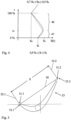
- FIG. 3 shows the rotor blade 23 schematically in an axial view, which illustrates the inclination of the rotor blade 23.
- the rotor blade 23 is inclined towards the suction side 41, specifically radially in the middle, based on the rotor blade height 45. Radially inward and radially outward, the inclination is less, the rotor blade 23 can also run into the hub or the housing without any inclination at all.
- the inclination towards the suction side 41 is set so that that the centrifugal force bending moment 48 acting on the rotor blade 23 during operation is greater than the gas force bending moment 49.
- the rotor blade 23 is bent towards the pressure side 42, which reduces the load there and thus the susceptibility to impact at the leading edge 23a, see also the introduction to the description.
- Figure 4 illustrates the relationship between the chord length S and the radius r, given as a percentage of the radial blade height. Radially inward, the blade has the chord length S;, radially outward it has the chord length S a . At a radial position r x in between, it has the chord length S x (which in this case represents a maximum). The radial position r x is between 20% and 50% of the radial blade height.
- chord length S decreases. This reduces the edge load and thus increases the impact tolerance in this area.
- the chord length S a is 0.7 to 0.9 times the chord length S x .
- chord length S does not decrease radially outward. It can either be constant (not shown) or as in Figure 4 shown even increase slightly towards the outside, i.e. decrease inwards from the radial position r x .
- the chord length S; radially inward is 0.9 to 1 times the chord length S x .
- the inventors have determined that, overall, there is no loss of robustness, see the introduction to the description for details. On the other hand, limiting the chord lengths radially inward allows for a more axially compact structure, which can be advantageous in terms of weight and efficiency, for example.
- Figure 5 illustrates the blade 23 in a tangential section.
- the chord length S is taken along a connecting tangent 50, which is placed on the pressure side of the profile and has an axially front contact point 51.1 and an axially rear contact point 51.2.
- the chord length S is then taken between two further tangents 52.1, 52.2, each of which is perpendicular to the connecting tangent 50, where the tangent 52.1 has a point of contact 53.1 axially at the front and the tangent 52.2 has a point of contact 53.2 axially at the rear.
Landscapes
- Engineering & Computer Science (AREA)
- Mechanical Engineering (AREA)
- General Engineering & Computer Science (AREA)
- Physics & Mathematics (AREA)
- Fluid Mechanics (AREA)
- Architecture (AREA)
- Structures Of Non-Positive Displacement Pumps (AREA)
- Turbine Rotor Nozzle Sealing (AREA)
Claims (15)
- Aube mobile (20) destinée à être disposée dans un canal de gaz (3) d'une turbomachine (1), comportant une pale d'aube mobile (23), laquellecomprend radialement à l'intérieur une longueur de corde Si,comprend radialement à l'extérieur une longueur de corde Sa, etcomprend une longueur de corde Sx à une position radiale rx entre les deux,dans laquelle la longueur de corde Sx à la position radiale rx est au moins aussi grande que la longueur de corde Si radialement à l'intérieur (Si ≤ Sx),caractérisée en ce que la longueur de corde Sa radialement à l'extérieur correspond au plus à 0,9 fois la longueur de corde Sx à la position radiale rx entre les deux (Sa ≤ 0,9 Sx),dans laquelle une évolution radiale de la longueur de corde S(r) depuis la position radiale rx radialement vers l'intérieur présente une diminution monotone de Sx vers Si, et dans laquelle la longueur de corde Si radialement à l'intérieur correspond au moins à 0,9 fois la longueur de corde Sx radialement entre les deux (Si ≥ 0,9 Sx).
- Aube mobile (20) selon la revendication 1, dans laquelle la position radiale rx avec la longueur de corde Sx, par rapport à une hauteur de pale d'aube mobile (45) prise depuis l'intérieur radialement vers l'extérieur radialement, est d'au moins 20 % et d'au plus 50 % de la hauteur de pale d'aube mobile (45).
- Aube mobile (20) selon l'une des revendications précédentes, dans laquelle la longueur de corde Sa radialement à l'extérieur correspond au moins à 0,7 fois la longueur de corde Sx radialement entre les deux (Sa ≥ 0,7 Sx).
- Aube mobile (20) selon l'une des revendications précédentes, dans laquelle une évolution radiale de la longueur de corde S(r) depuis la position radiale rx radialement vers l'extérieur présente une diminution monotone de Sx vers Sa.
- Aube mobile (20) selon la revendication 4, dans laquelle la diminution monotone de Sx vers Sa est strictement monotone et suit une pente constante.
- Aube mobile (20) selon la revendication 4, dans laquelle la diminution monotone de Sx vers Sa est strictement monotone et suit une pente croissante radialement vers l'extérieur en s'éloignant de la position radiale rx.
- Aube mobile (20) selon l'une des revendications précédentes, dans laquelle la diminution monotone de Sx vers Si est strictement monotone et suit une pente constante.
- Aube mobile (20) selon l'une des revendications 1 à 6, dans laquelle la diminution monotone de Sx vers Si est strictement monotone et suit une pente croissante radialement vers l'intérieur en s'éloignant de la position radiale rx.
- Aube mobile (20) selon l'une des revendications précédentes, dans laquelle la pale d'aube mobile (23) est prévue, par rapport à sa hauteur radiale de pale d'aube mobile (45), au moins dans certaines sections avec une inclinaison vers son côté aspiration (41), dans laquelle l'inclinaison est réglée de telle sorte que, lors d'un fonctionnement au point de conception aérodynamique (ADP), un moment de flexion de force centrifuge (48) que la force centrifuge provoque sur la pale d'aube mobile (23) en raison de l'inclinaison est supérieur à un moment de flexion de force du gaz (49) qui agit sur la pale d'aube mobile (23) en raison d'un écoulement autour de la pale d'aube mobile (23).
- Aube mobile (20) selon l'une des revendications précédentes, laquelle présente une bande de recouvrement extérieure (24) disposée radialement à l'extérieur sur la pale d'aube mobile (23), dans laquelle une seule pointe d'étanchéité (24.1) est disposée radialement à l'extérieur sur la bande de recouvrement extérieure (24).
- Aube mobile (20) selon l'une des revendications précédentes, dans laquelle au moins la pale d'aube mobile (23) est prévue en un matériau résistant aux hautes températures.
- Aube mobile (20) selon l'une des revendications précédentes, dans laquelle la pale d'aube mobile (23) est pourvue d'un revêtement (25) au moins sur le bord d'attaque (23a).
- Aube mobile (20) selon l'une des revendications précédentes, conçue pour un rotor à grande vitesse comportant, lors d'un fonctionnement au point de conception aérodynamique (ADP), une valeur An2 d'au moins 2000 m2/s2.
- Module de turbine (1ca, cb) pour un moteur d'aéronef, en particulier un moteur turboréacteur à double flux à réducteur, comportant une aube mobile (20) selon l'une des revendications précédentes, dans lequel le module de turbine (1ca, cb) est conçu pour amener un fluide de refroidissement à une bande de recouvrement extérieure (24) de l'aube mobile (20), dans lequel le fluide de refroidissement est amené depuis l'extérieur de l'aube mobile (20).
- Utilisation d'une aube mobile (20) selon l'une des revendications 1 à 13 ou d'un module de turbine (1ca, cb) selon la revendication 14, utilisation lors de laquelle l'aube mobile (20) tourne à une valeur An2 d'au moins 2000 m2/s2 lors d'un fonctionnement au point de conception aérodynamique (ADP).
Applications Claiming Priority (2)
| Application Number | Priority Date | Filing Date | Title |
|---|---|---|---|
| DE102019210693.5A DE102019210693A1 (de) | 2019-07-19 | 2019-07-19 | Laufschaufel für eine strömungsmaschine |
| PCT/DE2020/000155 WO2021013281A1 (fr) | 2019-07-19 | 2020-07-14 | Aube mobile destinée à une turbomachine, module de turbine associé et utilisation de l'aube mobile |
Publications (2)
| Publication Number | Publication Date |
|---|---|
| EP3999716A1 EP3999716A1 (fr) | 2022-05-25 |
| EP3999716B1 true EP3999716B1 (fr) | 2024-09-04 |
Family
ID=71994267
Family Applications (1)
| Application Number | Title | Priority Date | Filing Date |
|---|---|---|---|
| EP20753279.7A Active EP3999716B1 (fr) | 2019-07-19 | 2020-07-14 | Aube de rotor pour une turbomachine, module de turbine associé et utilisation des mêmes |
Country Status (5)
| Country | Link |
|---|---|
| US (1) | US12270315B2 (fr) |
| EP (1) | EP3999716B1 (fr) |
| DE (1) | DE102019210693A1 (fr) |
| ES (1) | ES2989274T3 (fr) |
| WO (1) | WO2021013281A1 (fr) |
Families Citing this family (7)
| Publication number | Priority date | Publication date | Assignee | Title |
|---|---|---|---|---|
| FR3143683A1 (fr) * | 2022-12-16 | 2024-06-21 | Safran Aircraft Engines | Systeme propulsif aeronautique |
| FR3143674A1 (fr) * | 2022-12-16 | 2024-06-21 | Safran Aircraft Engines | Systeme propulsif aeronautique |
| FR3143676A1 (fr) * | 2022-12-16 | 2024-06-21 | Safran Aircraft Engines | système PROPULSIF AERONAUTIQUE |
| FR3143672A1 (fr) | 2022-12-16 | 2024-06-21 | Safran Aircraft Engines | Systeme propulsif aeronautique |
| FR3143685A1 (fr) * | 2022-12-16 | 2024-06-21 | Safran Aircraft Engines | Systeme propulsif aeronautique |
| FR3143679A1 (fr) * | 2022-12-16 | 2024-06-21 | Safran Aircraft Engines | Système propulsif aéronautique |
| US12509988B2 (en) | 2024-06-14 | 2025-12-30 | Pratt & Whitney Canada Corp. | Turbine engine airfoil |
Family Cites Families (17)
| Publication number | Priority date | Publication date | Assignee | Title |
|---|---|---|---|---|
| US4012172A (en) * | 1975-09-10 | 1977-03-15 | Avco Corporation | Low noise blades for axial flow compressors |
| US4682935A (en) * | 1983-12-12 | 1987-07-28 | General Electric Company | Bowed turbine blade |
| US4741667A (en) | 1986-05-28 | 1988-05-03 | United Technologies Corporation | Stator vane |
| US5209643A (en) * | 1991-03-27 | 1993-05-11 | The Cessna Aircraft Company | Tapered propeller blade design |
| DE4310896C1 (de) | 1993-04-02 | 1994-03-24 | Thyssen Industrie | Verfahren zum Herstellen von verschleißfesten Kanten an Turbinenschaufeln |
| GB2293631B (en) | 1994-09-30 | 1998-09-09 | Gen Electric | Composite fan blade trailing edge reinforcement |
| US6328533B1 (en) | 1999-12-21 | 2001-12-11 | General Electric Company | Swept barrel airfoil |
| EP1582695A1 (fr) | 2004-03-26 | 2005-10-05 | Siemens Aktiengesellschaft | Aube de turbomachine |
| US7186092B2 (en) * | 2004-07-26 | 2007-03-06 | General Electric Company | Airfoil having improved impact and erosion resistance and method for preparing same |
| WO2007113149A1 (fr) | 2006-03-31 | 2007-10-11 | Alstom Technology Ltd | Aube directrice de turbomachine, notamment de turbine à vapeur |
| US9291062B2 (en) * | 2012-09-07 | 2016-03-22 | General Electric Company | Methods of forming blades and method for rendering a blade resistant to erosion |
| WO2015175073A2 (fr) * | 2014-02-19 | 2015-11-19 | United Technologies Corporation | Surface portante de moteur à turbine à gaz |
| EP3985226B1 (fr) | 2014-02-19 | 2024-12-25 | RTX Corporation | Profil d'aube pour moteur à turbine à gaz |
| US20150275675A1 (en) | 2014-03-27 | 2015-10-01 | General Electric Company | Bucket airfoil for a turbomachine |
| JP6461382B2 (ja) * | 2015-06-29 | 2019-01-30 | シーメンス アクチエンゲゼルシヤフトSiemens Aktiengesellschaft | シュラウド付きタービンブレード |
| US9957804B2 (en) * | 2015-12-18 | 2018-05-01 | General Electric Company | Turbomachine and turbine blade transfer |
| JP6782671B2 (ja) * | 2017-07-10 | 2020-11-11 | 三菱重工業株式会社 | ターボ機械 |
-
2019
- 2019-07-19 DE DE102019210693.5A patent/DE102019210693A1/de active Pending
-
2020
- 2020-07-14 WO PCT/DE2020/000155 patent/WO2021013281A1/fr not_active Ceased
- 2020-07-14 EP EP20753279.7A patent/EP3999716B1/fr active Active
- 2020-07-14 ES ES20753279T patent/ES2989274T3/es active Active
- 2020-07-14 US US17/597,674 patent/US12270315B2/en active Active
Also Published As
| Publication number | Publication date |
|---|---|
| DE102019210693A1 (de) | 2021-01-21 |
| US20220259977A1 (en) | 2022-08-18 |
| ES2989274T3 (es) | 2024-11-25 |
| WO2021013281A1 (fr) | 2021-01-28 |
| EP3999716A1 (fr) | 2022-05-25 |
| US12270315B2 (en) | 2025-04-08 |
Similar Documents
| Publication | Publication Date | Title |
|---|---|---|
| EP3999716B1 (fr) | Aube de rotor pour une turbomachine, module de turbine associé et utilisation des mêmes | |
| EP1953344B1 (fr) | Aube de turbine | |
| EP0846867B1 (fr) | Turbomachine avec un étage de compression transsonique | |
| DE602004006323T2 (de) | Verfahren zur Herstellung einer Turbine mit Turbinenschaufeln unterschiedlicher Resonanzfrequenzen samt einer solchen Turbine | |
| EP2647795B1 (fr) | Système d'étanchéité pour turbomachine | |
| EP3699398A1 (fr) | Aube sans bandage pour un étage de turbine à haute vitesse | |
| EP3467261B1 (fr) | Procédé de fabrication d'un élément d'aube en tandem | |
| EP3034788B1 (fr) | Aube de compresseur d'une turbine a gaz | |
| EP4077882B1 (fr) | Aube pour une turbomachine | |
| EP1757773A1 (fr) | Aube creuse de turbine | |
| EP3699399B1 (fr) | Aube pour un étage de turbine à grande vitesse dotée d'un élément d'étanchéité unique | |
| EP2458149B1 (fr) | Aubage pour turboréacteur | |
| EP3495639B1 (fr) | Module de compresseur pour une turbomachine réduisant la couche limite dans un carter intermédiaire de compresseur | |
| WO2016087214A1 (fr) | Aube mobile de turbine, rotor associé et turbomachine | |
| EP3274561B1 (fr) | Aube de rotor pour une turbine à gaz, procédé de fabrication et procédé de post-production | |
| DE102015221324A1 (de) | Turbinenrotor für eine Niederdruckturbine eines Gasturbinensystems | |
| EP2692989A2 (fr) | Aube de compresseur de turbine à gaz à faible module | |
| DE102019218911A1 (de) | Leitschaufelanordnung für eine strömungsmaschine | |
| EP4477839A2 (fr) | Procédé de détermination de la forme d'une aube désaccordée d'une roue porteuse d'une turbomachine | |
| EP4209657A1 (fr) | Aube, en particulier aube mobile ou aube directrice, avec profil de bord d'attaque asymétrique pour turbine à gaz | |
| EP4089264A1 (fr) | Agencement d'aubes pour turbines à gaz | |
| EP4265888A1 (fr) | Couronne d'aubes directrices et rotoriques pour un moteur à double flux | |
| WO2021013282A1 (fr) | Aube mobile pour une turbomachine, module de turbine associé et utilisation de celui-ci | |
| EP1462614B1 (fr) | Turbine thermique à écoulement axial | |
| EP4123123B1 (fr) | Aube de turbine pour un moteur à flux |
Legal Events
| Date | Code | Title | Description |
|---|---|---|---|
| STAA | Information on the status of an ep patent application or granted ep patent |
Free format text: STATUS: UNKNOWN |
|
| STAA | Information on the status of an ep patent application or granted ep patent |
Free format text: STATUS: THE INTERNATIONAL PUBLICATION HAS BEEN MADE |
|
| PUAI | Public reference made under article 153(3) epc to a published international application that has entered the european phase |
Free format text: ORIGINAL CODE: 0009012 |
|
| STAA | Information on the status of an ep patent application or granted ep patent |
Free format text: STATUS: REQUEST FOR EXAMINATION WAS MADE |
|
| 17P | Request for examination filed |
Effective date: 20220215 |
|
| AK | Designated contracting states |
Kind code of ref document: A1 Designated state(s): AL AT BE BG CH CY CZ DE DK EE ES FI FR GB GR HR HU IE IS IT LI LT LU LV MC MK MT NL NO PL PT RO RS SE SI SK SM TR |
|
| DAV | Request for validation of the european patent (deleted) | ||
| DAX | Request for extension of the european patent (deleted) | ||
| GRAP | Despatch of communication of intention to grant a patent |
Free format text: ORIGINAL CODE: EPIDOSNIGR1 |
|
| STAA | Information on the status of an ep patent application or granted ep patent |
Free format text: STATUS: GRANT OF PATENT IS INTENDED |
|
| INTG | Intention to grant announced |
Effective date: 20240422 |
|
| GRAS | Grant fee paid |
Free format text: ORIGINAL CODE: EPIDOSNIGR3 |
|
| GRAA | (expected) grant |
Free format text: ORIGINAL CODE: 0009210 |
|
| STAA | Information on the status of an ep patent application or granted ep patent |
Free format text: STATUS: THE PATENT HAS BEEN GRANTED |
|
| AK | Designated contracting states |
Kind code of ref document: B1 Designated state(s): AL AT BE BG CH CY CZ DE DK EE ES FI FR GB GR HR HU IE IS IT LI LT LU LV MC MK MT NL NO PL PT RO RS SE SI SK SM TR |
|
| REG | Reference to a national code |
Ref country code: GB Ref legal event code: FG4D Free format text: NOT ENGLISH |
|
| REG | Reference to a national code |
Ref country code: CH Ref legal event code: EP |
|
| REG | Reference to a national code |
Ref country code: IE Ref legal event code: FG4D Free format text: LANGUAGE OF EP DOCUMENT: GERMAN |
|
| REG | Reference to a national code |
Ref country code: DE Ref legal event code: R096 Ref document number: 502020009126 Country of ref document: DE |
|
| REG | Reference to a national code |
Ref country code: ES Ref legal event code: FG2A Ref document number: 2989274 Country of ref document: ES Kind code of ref document: T3 Effective date: 20241125 |
|
| REG | Reference to a national code |
Ref country code: LT Ref legal event code: MG9D |
|
| REG | Reference to a national code |
Ref country code: NL Ref legal event code: MP Effective date: 20240904 |
|
| PG25 | Lapsed in a contracting state [announced via postgrant information from national office to epo] |
Ref country code: NO Free format text: LAPSE BECAUSE OF FAILURE TO SUBMIT A TRANSLATION OF THE DESCRIPTION OR TO PAY THE FEE WITHIN THE PRESCRIBED TIME-LIMIT Effective date: 20241204 |
|
| PG25 | Lapsed in a contracting state [announced via postgrant information from national office to epo] |
Ref country code: PL Free format text: LAPSE BECAUSE OF FAILURE TO SUBMIT A TRANSLATION OF THE DESCRIPTION OR TO PAY THE FEE WITHIN THE PRESCRIBED TIME-LIMIT Effective date: 20240904 Ref country code: GR Free format text: LAPSE BECAUSE OF FAILURE TO SUBMIT A TRANSLATION OF THE DESCRIPTION OR TO PAY THE FEE WITHIN THE PRESCRIBED TIME-LIMIT Effective date: 20241205 Ref country code: FI Free format text: LAPSE BECAUSE OF FAILURE TO SUBMIT A TRANSLATION OF THE DESCRIPTION OR TO PAY THE FEE WITHIN THE PRESCRIBED TIME-LIMIT Effective date: 20240904 |
|
| PG25 | Lapsed in a contracting state [announced via postgrant information from national office to epo] |
Ref country code: BG Free format text: LAPSE BECAUSE OF FAILURE TO SUBMIT A TRANSLATION OF THE DESCRIPTION OR TO PAY THE FEE WITHIN THE PRESCRIBED TIME-LIMIT Effective date: 20240904 |
|
| PG25 | Lapsed in a contracting state [announced via postgrant information from national office to epo] |
Ref country code: LV Free format text: LAPSE BECAUSE OF FAILURE TO SUBMIT A TRANSLATION OF THE DESCRIPTION OR TO PAY THE FEE WITHIN THE PRESCRIBED TIME-LIMIT Effective date: 20240904 |
|
| PG25 | Lapsed in a contracting state [announced via postgrant information from national office to epo] |
Ref country code: HR Free format text: LAPSE BECAUSE OF FAILURE TO SUBMIT A TRANSLATION OF THE DESCRIPTION OR TO PAY THE FEE WITHIN THE PRESCRIBED TIME-LIMIT Effective date: 20240904 |
|
| PG25 | Lapsed in a contracting state [announced via postgrant information from national office to epo] |
Ref country code: RS Free format text: LAPSE BECAUSE OF FAILURE TO SUBMIT A TRANSLATION OF THE DESCRIPTION OR TO PAY THE FEE WITHIN THE PRESCRIBED TIME-LIMIT Effective date: 20241204 |
|
| PG25 | Lapsed in a contracting state [announced via postgrant information from national office to epo] |
Ref country code: RS Free format text: LAPSE BECAUSE OF FAILURE TO SUBMIT A TRANSLATION OF THE DESCRIPTION OR TO PAY THE FEE WITHIN THE PRESCRIBED TIME-LIMIT Effective date: 20241204 Ref country code: PL Free format text: LAPSE BECAUSE OF FAILURE TO SUBMIT A TRANSLATION OF THE DESCRIPTION OR TO PAY THE FEE WITHIN THE PRESCRIBED TIME-LIMIT Effective date: 20240904 Ref country code: NO Free format text: LAPSE BECAUSE OF FAILURE TO SUBMIT A TRANSLATION OF THE DESCRIPTION OR TO PAY THE FEE WITHIN THE PRESCRIBED TIME-LIMIT Effective date: 20241204 Ref country code: LV Free format text: LAPSE BECAUSE OF FAILURE TO SUBMIT A TRANSLATION OF THE DESCRIPTION OR TO PAY THE FEE WITHIN THE PRESCRIBED TIME-LIMIT Effective date: 20240904 Ref country code: HR Free format text: LAPSE BECAUSE OF FAILURE TO SUBMIT A TRANSLATION OF THE DESCRIPTION OR TO PAY THE FEE WITHIN THE PRESCRIBED TIME-LIMIT Effective date: 20240904 Ref country code: GR Free format text: LAPSE BECAUSE OF FAILURE TO SUBMIT A TRANSLATION OF THE DESCRIPTION OR TO PAY THE FEE WITHIN THE PRESCRIBED TIME-LIMIT Effective date: 20241205 Ref country code: FI Free format text: LAPSE BECAUSE OF FAILURE TO SUBMIT A TRANSLATION OF THE DESCRIPTION OR TO PAY THE FEE WITHIN THE PRESCRIBED TIME-LIMIT Effective date: 20240904 Ref country code: BG Free format text: LAPSE BECAUSE OF FAILURE TO SUBMIT A TRANSLATION OF THE DESCRIPTION OR TO PAY THE FEE WITHIN THE PRESCRIBED TIME-LIMIT Effective date: 20240904 |
|
| PG25 | Lapsed in a contracting state [announced via postgrant information from national office to epo] |
Ref country code: NL Free format text: LAPSE BECAUSE OF FAILURE TO SUBMIT A TRANSLATION OF THE DESCRIPTION OR TO PAY THE FEE WITHIN THE PRESCRIBED TIME-LIMIT Effective date: 20240904 |
|
| PG25 | Lapsed in a contracting state [announced via postgrant information from national office to epo] |
Ref country code: PT Free format text: LAPSE BECAUSE OF FAILURE TO SUBMIT A TRANSLATION OF THE DESCRIPTION OR TO PAY THE FEE WITHIN THE PRESCRIBED TIME-LIMIT Effective date: 20250106 Ref country code: IS Free format text: LAPSE BECAUSE OF FAILURE TO SUBMIT A TRANSLATION OF THE DESCRIPTION OR TO PAY THE FEE WITHIN THE PRESCRIBED TIME-LIMIT Effective date: 20250104 |
|
| PG25 | Lapsed in a contracting state [announced via postgrant information from national office to epo] |
Ref country code: RO Free format text: LAPSE BECAUSE OF FAILURE TO SUBMIT A TRANSLATION OF THE DESCRIPTION OR TO PAY THE FEE WITHIN THE PRESCRIBED TIME-LIMIT Effective date: 20240904 Ref country code: SM Free format text: LAPSE BECAUSE OF FAILURE TO SUBMIT A TRANSLATION OF THE DESCRIPTION OR TO PAY THE FEE WITHIN THE PRESCRIBED TIME-LIMIT Effective date: 20240904 |
|
| PG25 | Lapsed in a contracting state [announced via postgrant information from national office to epo] |
Ref country code: EE Free format text: LAPSE BECAUSE OF FAILURE TO SUBMIT A TRANSLATION OF THE DESCRIPTION OR TO PAY THE FEE WITHIN THE PRESCRIBED TIME-LIMIT Effective date: 20240904 |
|
| PG25 | Lapsed in a contracting state [announced via postgrant information from national office to epo] |
Ref country code: CZ Free format text: LAPSE BECAUSE OF FAILURE TO SUBMIT A TRANSLATION OF THE DESCRIPTION OR TO PAY THE FEE WITHIN THE PRESCRIBED TIME-LIMIT Effective date: 20240904 |
|
| PG25 | Lapsed in a contracting state [announced via postgrant information from national office to epo] |
Ref country code: SK Free format text: LAPSE BECAUSE OF FAILURE TO SUBMIT A TRANSLATION OF THE DESCRIPTION OR TO PAY THE FEE WITHIN THE PRESCRIBED TIME-LIMIT Effective date: 20240904 Ref country code: IT Free format text: LAPSE BECAUSE OF FAILURE TO SUBMIT A TRANSLATION OF THE DESCRIPTION OR TO PAY THE FEE WITHIN THE PRESCRIBED TIME-LIMIT Effective date: 20240904 |
|
| REG | Reference to a national code |
Ref country code: DE Ref legal event code: R097 Ref document number: 502020009126 Country of ref document: DE |
|
| PG25 | Lapsed in a contracting state [announced via postgrant information from national office to epo] |
Ref country code: DK Free format text: LAPSE BECAUSE OF FAILURE TO SUBMIT A TRANSLATION OF THE DESCRIPTION OR TO PAY THE FEE WITHIN THE PRESCRIBED TIME-LIMIT Effective date: 20240904 |
|
| PLBE | No opposition filed within time limit |
Free format text: ORIGINAL CODE: 0009261 |
|
| STAA | Information on the status of an ep patent application or granted ep patent |
Free format text: STATUS: NO OPPOSITION FILED WITHIN TIME LIMIT |
|
| 26N | No opposition filed |
Effective date: 20250605 |
|
| PG25 | Lapsed in a contracting state [announced via postgrant information from national office to epo] |
Ref country code: SE Free format text: LAPSE BECAUSE OF FAILURE TO SUBMIT A TRANSLATION OF THE DESCRIPTION OR TO PAY THE FEE WITHIN THE PRESCRIBED TIME-LIMIT Effective date: 20240904 |
|
| PGFP | Annual fee paid to national office [announced via postgrant information from national office to epo] |
Ref country code: ES Payment date: 20250819 Year of fee payment: 6 |
|
| PGFP | Annual fee paid to national office [announced via postgrant information from national office to epo] |
Ref country code: DE Payment date: 20250722 Year of fee payment: 6 |
|
| PGFP | Annual fee paid to national office [announced via postgrant information from national office to epo] |
Ref country code: GB Payment date: 20250724 Year of fee payment: 6 |
|
| PGFP | Annual fee paid to national office [announced via postgrant information from national office to epo] |
Ref country code: FR Payment date: 20250723 Year of fee payment: 6 |
|
| REG | Reference to a national code |
Ref country code: CH Ref legal event code: H13 Free format text: ST27 STATUS EVENT CODE: U-0-0-H10-H13 (AS PROVIDED BY THE NATIONAL OFFICE) Effective date: 20260224 |
|
| PG25 | Lapsed in a contracting state [announced via postgrant information from national office to epo] |
Ref country code: LU Free format text: LAPSE BECAUSE OF NON-PAYMENT OF DUE FEES Effective date: 20250714 |
|
| REG | Reference to a national code |
Ref country code: BE Ref legal event code: MM Effective date: 20250731 |
|
| PG25 | Lapsed in a contracting state [announced via postgrant information from national office to epo] |
Ref country code: BE Free format text: LAPSE BECAUSE OF NON-PAYMENT OF DUE FEES Effective date: 20250731 |
|
| PG25 | Lapsed in a contracting state [announced via postgrant information from national office to epo] |
Ref country code: CH Free format text: LAPSE BECAUSE OF NON-PAYMENT OF DUE FEES Effective date: 20250731 |