EP4077882B1 - Aube pour une turbomachine - Google Patents
Aube pour une turbomachine Download PDFInfo
- Publication number
- EP4077882B1 EP4077882B1 EP20841652.9A EP20841652A EP4077882B1 EP 4077882 B1 EP4077882 B1 EP 4077882B1 EP 20841652 A EP20841652 A EP 20841652A EP 4077882 B1 EP4077882 B1 EP 4077882B1
- Authority
- EP
- European Patent Office
- Prior art keywords
- leading edge
- rotor blade
- blade
- blade airfoil
- edge radius
- Prior art date
- Legal status (The legal status is an assumption and is not a legal conclusion. Google has not performed a legal analysis and makes no representation as to the accuracy of the status listed.)
- Active
Links
Images
Classifications
-
- F—MECHANICAL ENGINEERING; LIGHTING; HEATING; WEAPONS; BLASTING
- F01—MACHINES OR ENGINES IN GENERAL; ENGINE PLANTS IN GENERAL; STEAM ENGINES
- F01D—NON-POSITIVE DISPLACEMENT MACHINES OR ENGINES, e.g. STEAM TURBINES
- F01D5/00—Blades; Blade-carrying members; Heating, heat-insulating, cooling or antivibration means on the blades or the members
- F01D5/12—Blades
- F01D5/14—Form or construction
- F01D5/141—Shape, i.e. outer, aerodynamic form
-
- F—MECHANICAL ENGINEERING; LIGHTING; HEATING; WEAPONS; BLASTING
- F01—MACHINES OR ENGINES IN GENERAL; ENGINE PLANTS IN GENERAL; STEAM ENGINES
- F01D—NON-POSITIVE DISPLACEMENT MACHINES OR ENGINES, e.g. STEAM TURBINES
- F01D5/00—Blades; Blade-carrying members; Heating, heat-insulating, cooling or antivibration means on the blades or the members
- F01D5/12—Blades
- F01D5/28—Selecting particular materials; Particular measures relating thereto; Measures against erosion or corrosion
-
- F—MECHANICAL ENGINEERING; LIGHTING; HEATING; WEAPONS; BLASTING
- F05—INDEXING SCHEMES RELATING TO ENGINES OR PUMPS IN VARIOUS SUBCLASSES OF CLASSES F01-F04
- F05D—INDEXING SCHEME FOR ASPECTS RELATING TO NON-POSITIVE-DISPLACEMENT MACHINES OR ENGINES, GAS-TURBINES OR JET-PROPULSION PLANTS
- F05D2220/00—Application
- F05D2220/30—Application in turbines
- F05D2220/32—Application in turbines in gas turbines
- F05D2220/323—Application in turbines in gas turbines for aircraft propulsion, e.g. jet engines
-
- F—MECHANICAL ENGINEERING; LIGHTING; HEATING; WEAPONS; BLASTING
- F05—INDEXING SCHEMES RELATING TO ENGINES OR PUMPS IN VARIOUS SUBCLASSES OF CLASSES F01-F04
- F05D—INDEXING SCHEME FOR ASPECTS RELATING TO NON-POSITIVE-DISPLACEMENT MACHINES OR ENGINES, GAS-TURBINES OR JET-PROPULSION PLANTS
- F05D2240/00—Components
- F05D2240/20—Rotors
- F05D2240/30—Characteristics of rotor blades, i.e. of any element transforming dynamic fluid energy to or from rotational energy and being attached to a rotor
-
- F—MECHANICAL ENGINEERING; LIGHTING; HEATING; WEAPONS; BLASTING
- F05—INDEXING SCHEMES RELATING TO ENGINES OR PUMPS IN VARIOUS SUBCLASSES OF CLASSES F01-F04
- F05D—INDEXING SCHEME FOR ASPECTS RELATING TO NON-POSITIVE-DISPLACEMENT MACHINES OR ENGINES, GAS-TURBINES OR JET-PROPULSION PLANTS
- F05D2240/00—Components
- F05D2240/20—Rotors
- F05D2240/30—Characteristics of rotor blades, i.e. of any element transforming dynamic fluid energy to or from rotational energy and being attached to a rotor
- F05D2240/301—Cross-sectional characteristics
-
- F—MECHANICAL ENGINEERING; LIGHTING; HEATING; WEAPONS; BLASTING
- F05—INDEXING SCHEMES RELATING TO ENGINES OR PUMPS IN VARIOUS SUBCLASSES OF CLASSES F01-F04
- F05D—INDEXING SCHEME FOR ASPECTS RELATING TO NON-POSITIVE-DISPLACEMENT MACHINES OR ENGINES, GAS-TURBINES OR JET-PROPULSION PLANTS
- F05D2240/00—Components
- F05D2240/20—Rotors
- F05D2240/30—Characteristics of rotor blades, i.e. of any element transforming dynamic fluid energy to or from rotational energy and being attached to a rotor
- F05D2240/303—Characteristics of rotor blades, i.e. of any element transforming dynamic fluid energy to or from rotational energy and being attached to a rotor related to the leading edge of a rotor blade
-
- Y—GENERAL TAGGING OF NEW TECHNOLOGICAL DEVELOPMENTS; GENERAL TAGGING OF CROSS-SECTIONAL TECHNOLOGIES SPANNING OVER SEVERAL SECTIONS OF THE IPC; TECHNICAL SUBJECTS COVERED BY FORMER USPC CROSS-REFERENCE ART COLLECTIONS [XRACs] AND DIGESTS
- Y02—TECHNOLOGIES OR APPLICATIONS FOR MITIGATION OR ADAPTATION AGAINST CLIMATE CHANGE
- Y02T—CLIMATE CHANGE MITIGATION TECHNOLOGIES RELATED TO TRANSPORTATION
- Y02T50/00—Aeronautics or air transport
- Y02T50/60—Efficient propulsion technologies, e.g. for aircraft
Definitions
- the present invention relates to a rotor blade for a turbomachine.
- the turbomachine can be a jet engine, for example a turbofan engine. Functionally, the turbomachine is divided into a compressor, combustion chamber and turbine. In the case of a jet engine, for example, the air drawn in is compressed by the compressor and burned in the downstream combustion chamber with added kerosene. The resulting hot gas, a mixture of combustion gas and air, flows through the downstream turbine and is expanded in the process.
- the turbine is usually made up of several stages, each with a stator (guide vane ring) and a rotor (blade ring); the rotors are driven by the hot gas. In each stage, a proportion of the internal energy is extracted from the hot gas, which is converted into a movement of the respective blade ring and thus the shaft.
- Blades for turbomachines are from the documents US20180231018A1 , EP2927427A1 and EP1927724A2 known.
- the present subject matter relates to a rotor blade for placement in the gas channel of the turbomachine.
- the rotor blade can generally also be used in the compressor area, i.e. it can be placed in the compressor gas channel; it is preferred to be used in the turbine area, i.e. it is placed in the hot gas channel.
- the present invention is based on the technical problem of specifying a particularly advantageous rotor blade.
- the thickening of the blade profile is specified via the ratio between its blade thickness d and leading edge radius R VK in such a way that 2 ⁇ d R VK 2 ⁇ d not more than 5.5.
- Other advantageous upper limits are, in increasing order of preference, not more than 5.0, 4.5 and 4.0.
- the thickening allows a more robust profile with a higher impact tolerance to be created, which can therefore withstand a higher impact load.
- the thickening can also be advantageous during a revision, for example, when removing material from damaged areas, larger rework limits can be granted.
- the design measure in accordance with the main claim still results in a profile that is acceptable in terms of flow technology, so the aerodynamic properties are not significantly impaired.
- the blade thickness d and the leading edge radius R VK are to be inserted into the formula as sizes given in millimeters, whereby the calculation itself is then carried out without units.
- the blade is thickened at the leading edge or in an area located there.
- formula 1 is fulfilled at least in a distance range between 1 mm and 2.5 mm, preferably it applies at least in a distance range between 0.7 mm and 2.8 mm.
- Formula 1 can be used in particular for distance values A of 1 mm and/or 1.5 mm and/or 2 mm and/or 2.5 mm must be met.
- the blade is therefore thickened in an area close to the leading edge, although there may also be a thickening further back (cf. Figure 2 for illustration purposes).
- This can result, for example, from an aerodynamic profile, i.e. a profile continuation to the trailing edge without aerodynamically disadvantageous turning points.
- the larger leading edge radius can also result, for example, in a profile with a larger surface area, which can reduce the mean stress in the individual profile sections and thus increase the impact tolerance.
- Thickening the profile on the pressure side can, for example, be advantageous in that the profile area can be increased without axially extending the chord length, which leads to a reduction in stress. In particular, this can reduce or avoid an increase in the axial length and thus the axial length of the turbine stage or module.
- axial refers to the axis of rotation around which the rotor blade rotates during operation. This typically coincides with a longitudinal axis of the engine or engine module.
- the blade profile is viewed in a tangential section, i.e. in a cutting plane parallel to the axis.
- the leading edge radius R VK is determined by a circle fitted into the leading edge area (see below) and the blade thickness d is obtained perpendicular to the skeleton line between the suction and pressure side surfaces of the blade.
- the skeleton line is defined by the centers of circles that are so are fitted into the profile so that each of the circles touches the suction and pressure side surfaces.
- the leading edge radius R VK is less than 2 mm.
- R VK is ⁇ 1.8 mm, in particular ⁇ 1.4 mm and/or ⁇ 1.3 mm.
- the leading edge radius R VK is ⁇ 0.2 mm, in particular ⁇ 0.6 mm and/or ⁇ 0.7 mm.
- R VK is in the range from 0.6 mm to 1.4 mm, in particular from 0.8 mm to 1.0 mm or from 0.1 mm to 1.3 mm.
- the blade thickness d in the leading edge area is between 0.5 mm and 5 mm, preferably between 1.5 mm and 4 mm, in particular between 2 mm and 2.5 mm
- the blade thickness d and the leading edge radius R VK are adjusted such that 2 ⁇ d R VK 2 ⁇ d at least 0.6.
- Other advantageous lower limits are 0.7, 0.8 and 0.9, in the order in which they are mentioned, which are increasingly preferred.
- the flow losses can be kept low with the present subject matter, especially when profiles of different thicknesses are provided for vibration-mechanical reasons ( detuning ) . It is then possible, for example, to at least partially or completely avoid a pressure-side separation bubble on the thin profile, which keeps the flow loss low overall.
- a leading edge area in which the blade profile has the leading edge radius R VK extends, based on the distance A taken along the skeleton line, preferably to at least 0.10 mm, more preferably at least 1.50 mm. Possible upper limits can be, in increasing order of preference, at most 0.30 mm, 0.25 mm and 0.20 mm. These distance values are each applied to the suction and pressure side surface with a Straight lines are transferred; this crosses the skeleton line, for example, at 1.50 mm if the leading edge area extends to this distance A.
- the blade height H is taken from the radial inside to the outside, i.e. from the blade root or inner shroud to the blade tip or outer shroud.
- the blade can be thickened over the entire blade height H or just in a section of it.
- the blade thickness d is increased at least in the radial positions between 60% and 90% of the blade height H, i.e. the ratio according to the main claim is met in tangential sections at these radial positions. This particularly preferably applies to the radial positions between 50% and 90% of the blade height H.
- the inventors have found that the frequency of impacts and the impact load resulting from the speed and mass are not evenly distributed radially, but are higher radially on the outside. The blade is therefore thickened at least there.
- a preferred embodiment relates to a ratio of the blade thickness d and the leading edge radius R VK , as well as the chord length l.
- the chord length is taken from the blade profile like the leading edge radius R VK and the blade thickness d. In detail, the length is then taken along a connecting tangent laid on the pressure side of the profile in the tangential section, which does not intersect the blade and has two points of contact with the blade (in the area of the leading edge and in the area of the trailing edge).
- chord length is then obtained along these connecting tangents as the distance between a front and a rear tangent, with the front and rear tangents each being perpendicular to the connecting tangent and touching (and not intersecting) the blade at the front (front tangent) and the rear (rear tangent).
- the blade thickness d, the leading edge radius R VK and the chord length are set such that d R VK ⁇ l is at most 7.2.
- Advantageous upper limits are, in the order of mention, increasingly preferred at most 7.0, 6.9, 6.8, 6.7, 6.6, or 6.5.
- Advantageous lower limits are, in the order of mention, increasingly preferred at most 4.0, 4.2, or 4.4. In this case too, the values are used in millimeters and the calculation is carried out without units. With this design rule, a profile can be realized that is structurally robust on the one hand, but which also has good aerodynamic properties on the other.
- this criterion is met in a distance range between 1 mm and 2 mm from the front edge (based on the distance A taken along the skeleton line), particularly preferably between 0.7 mm and 2.5 mm. Compared to the design rule discussed at the beginning, this criterion may be somewhat more critical with regard to the front edge distance, which is why the area is closer to the front edge.
- the criterion can be met in particular at distances A of 1 mm and/or 1.5 mm and/or 2 mm and/or 2.5 mm.
- At least the rotor blade is made of a brittle material, preferably the rotor blade as a whole.
- a brittle material that has a maximum total elongation of less than 6%, preferably less than 4%, in particular less than 2%, can be more critical in terms of structural mechanics, i.e. can also have a higher susceptibility to impact, for example.
- the possibility of providing a brittle material opened up by the thickening according to the invention can make interesting materials accessible that are advantageous for the overall system.
- the rotor blade is made of a high-temperature-resistant material.
- “High-temperature-resistant” can mean suitability for temperatures up to at least 700 °C or even 800 °C, whereby such high-temperature resistance is usually accompanied by lower ductility. This results in a higher susceptibility to impact, which is counteracted with the measures described here. Modifications to the microstructure are also possible in order to increase the ductility of the brittle material.
- the high-temperature-resistant material can in particular be titanium aluminide, preferably an intermetallic TiAl material or a TiAl alloy. In the context of the present invention, this refers to materials that have titanium and aluminum as their main components, as well as intermetallic phases, e.g. Ti3Al, ⁇ -TiAl.
- the blade or the blade can in particular be made of a TNM alloy (titanium, niobium, molybdenum, e.g. 43.5 at. % Al, 4 at. % Nb, 1 at. % Mo and 0.1 at. % boron, the rest being titanium or unavoidable impurities).
- the rotor blade preferably the rotor blade as a whole, can be manufactured, for example, by casting, forging and/or generative manufacturing as well as final contour milling (in particular from the high-temperature-resistant material).
- the rotor blade can, for example, have a rotor blade root that can be mounted in a rotor disk.
- the rotor blade can also be combined with another or more rotor blades to form an integral multiple segment, and it can also be part of a blisk ( blade integrated disk ) .
- the blade is a solid profile, i.e. not a hollow profile or hollow blade. In the tangential section, the blade is therefore free of cavities (no cavities).
- the rotor blade is designed for a high-speed rotor, in particular of a high-speed turbine module.
- Values of An 2 of at least 2000 m 2 /s 2 are considered "high-speed", in the order in which they are mentioned, increasingly preferred are at least 2500 m 2 /s 2 , 3000 m 2 /s 2 , 3500 m 2 /s 2 , 4000 m 2 /s 2 , 4500 m 2 /s 2 or 5000 m 2 /s 2 (possible upper limits can be, for example, at most 9000 m 2 /s 2 , 7000 m 2 /s 2 or 6000 m 2 /s 2 ).
- An 2 In the case of a conventional rotor blade not designed for high-speed operation, An 2, for example, can be around 1800 m 2 /s 2. In general, An 2 is calculated over the annular space area, particularly at the outlet, multiplied by the speed in the ADP range squared.
- the aerodynamic design point (ADP) is calculated under cruise conditions at cruising altitude; it is characterized by ideal flow conditions and the best efficiency and thus the lowest consumption.
- the rotational speed at the blade tip radially outside
- this can be up to a maximum of 220 m/s for a conventional rotor blade, for example, but more than 300 m/s or even 400 m/s for a high-speed rotor blade.
- the invention also relates to a turbine module for an aircraft engine, in particular a geared turbo fan engine, with a rotor blade as disclosed here.
- the turbine module can be designed in particular for "high-speed" operation of the rotor blade, see the information in the previous paragraph. Due to the coupling via the gear, the turbine module can rotate faster than the fan of the aircraft engine during operation (this means "high-speed”).
- the turbine module can be a low-pressure turbine module, for example.
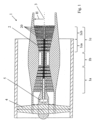
- FIG. 1 shows a turbomachine 1 in a schematic view, specifically a bypass engine.
- the turbomachine 1 is functionally divided into compressor 1a, combustion chamber 1b and turbine 1c, the latter having a high-pressure turbine module 1ca and a low-pressure turbine module 1cb.
- Both the compressor 1a and the turbine 1c are each made up of several stages, each stage consisting of a guide vane and a rotor blade ring.
- the rotor blade In relation to the flow in the gas channel 2, the rotor blade is arranged downstream of the guide vane ring in each stage.
- the rotor blades rotate about the longitudinal axis 3.
- the fan 4 is coupled via a gear 5, the rotor blade rings of the low-pressure turbine module 1cb rotate faster than the fan 4 during operation.
- the reference number 20 indicates some rotor blades as an example.
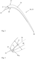
- Figure 2 shows a rotor blade 23 in a tangential section for a rotor blade 20 of the turbine 1c, specifically of the low-pressure turbine module 1cb.
- the cutting plane is therefore perpendicular to the drawing plane and horizontal.
- Figure 2 thus shows the blade profile 24, which extends from a leading edge 25 to a trailing edge 26 is clamped between a suction side 27 and a pressure side 28.
- the solid lines indicate Figure 2 a profile that is only aerodynamically optimized. As explained in detail in the introduction to the description, this can, however, be disadvantageous in terms of structural mechanics, in particular it can have too low an impact tolerance.
- the dashed line shows an airfoil profile 24 that has been thickened according to the invention; the airfoil thickness d is increased in particular in an area at the leading edge 25, which improves the impact resistance.
- FIG 3 shows the area at the leading edge 25 in detail.
- the blade thickness d is taken perpendicular to the skeleton line 30.
- the blade profile 24 has a leading edge radius R VK (a corresponding circular arc is shown in dotted lines).
- a leading edge area 35 over which the rotor blade 23 has the leading edge radius R VK , extends over around 0.15 mm.
- a circle or circular arc whose center lies on the skeleton line 30 can be fitted into several points in the leading edge area 35, e.g. by "best fit".
- the thickening is set so that 2 ⁇ d R VK 2 ⁇ d
- the thickening achieved in this way is not only advantageous in terms of structural mechanics, but also aerodynamics, see the description introduction in detail.
- the thickening is particularly present in an area close to the leading edge.
- the rotor blade 23 can be optimized accordingly, especially in a radially outer section.
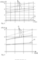
- Figure 4 illustrated for different distances A from the front edge 25, shown here in millimetres (cf. Figure 3 ) the ratio according to the above formula.
- the curve 40 shows the values taken from the blade profile 24 optimized according to the invention; for comparison, the curves 41 show values taken from different profiles, each of which is optimized solely aerodynamically.
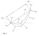
- Figure 5 shows how the chord length l is determined using an airfoil profile 24. This is taken along a connecting tangent 50, which is placed on the pressure side of the airfoil profile 24 and has an axially forward contact point 51.1 and an axially rear contact point 51.2. The chord length l is then taken between two further tangents 52.1, 52.2, each of which is perpendicular to the connecting tangent 50, with the tangent 52.1 having a contact point 53.1 axially forward and the tangent 52.2 having a contact point 53.2 axially rear.
- Figure 6 illustrates a relationship set according to the invention between the blade thickness d, the leading edge radius R VK and the chord length l, again plotted against the distance A taken from the leading edge 25 along the skeleton line 30.
- the curve 60 is taken based on a structurally and aerodynamically optimized blade profile 24, whereas the curves 61 only show aerodynamically optimized profiles for comparison.
Landscapes
- Engineering & Computer Science (AREA)
- Mechanical Engineering (AREA)
- General Engineering & Computer Science (AREA)
- Physics & Mathematics (AREA)
- Fluid Mechanics (AREA)
- Chemical & Material Sciences (AREA)
- Materials Engineering (AREA)
- Structures Of Non-Positive Displacement Pumps (AREA)
- Turbine Rotor Nozzle Sealing (AREA)
Claims (11)
- Aube mobile (20) destinée à être disposée dans un canal de gaz (2) d'une turbomachine (1), à savoir d'un turboréacteur, comportant une pale d'aube mobile (23) qui, vue en coupe tangentielle, c'est-à-dire dans un plan de coupe parallèle à l'axe, possède un profil de pale d'aube (24) comportant- un rayon de bord d'attaque RVK qui est déterminé par l'intermédiaire d'un cercle inséré dans la zone de bord d'attaque, et- une épaisseur de pale d'aube d,caractérisée en ce que le profil de pale d'aube (24) est épaissi au moins dans certaines sections, à savoir au moins dans une zone disposée au niveau du bord d'attaque, à savoir l'épaisseur de pale d'aube d est réglée par rapport au rayon de bord d'attaque RVK de telle sorteque, par rapport à une distance A prise le long de la ligne d'ossature en s'éloignant du bord d'attaque, la formule suivante (2·d / RVK 2) - d ≤ 5,5est satisfaite au moins dans une plage de distances comprise entre 1 mm et 2,5 mm, dans laquelle l'épaisseur de pale d'aube d et le rayon de bord d'attaque RVK doivent être utilisés dans la formule en tant que grandeurs indiquées en millimètres et le calcul en soi est effectué alors sans unité, dans laquelle le rayon de bord d'attaque RVK est compris dans la plage allant de 0,2 mm à 1,8 mm et l'épaisseur de pale d'aube d dans la zone de bord d'attaque, à savoir pour des valeurs d'une distance prise le long de la ligne d'ossature en s'éloignant du bord d'attaque, lesquelles valeurs se situent dans la plage allant de 1 mm à 2,5 mm, est comprise entre 0,5 mm et 5 mm.
- Aube mobile (20) selon la revendication 1, dans laquelle l'épaisseur de pale d'aube d est réglée par rapport au rayon de bord d'attaque RVK de telle sorte que 0,6 ≤ (2·d / RVK 2) - d ≤ 5,0, dans laquelle l'épaisseur de pale d'aube d et le rayon de bord d'attaque RVK doivent être utilisés dans la formule en tant que grandeurs indiquées en millimètres et le calcul en soi est effectué alors sans unité, et/ou dans laquelle le rayon de bord d'attaque RVK se situe dans la plage allant de 0,6 mm à 1,4 mm, en particulier de 0,7 mm à 1,4 mm, et/ou dans laquelle l'épaisseur de pale d'aube d dans la zone de bord d'attaque, en particulier pour des valeurs d'une distance prise le long de la ligne d'ossature en s'éloignant du bord d'attaque, lesquelles valeurs se situent dans la plage allant de 1 mm à 2,5 mm, est comprise entre 1,5 mm et 4 mm, en particulier entre 2 mm et 2,5 mm.
- Aube mobile (20) selon l'une des revendications précédentes, dans laquelle une zone de bord d'attaque (35) dans laquelle le profil de pale d'aube (24) possède le rayon de bord d'attaque RVK, par rapport à une distance A prise le long d'une ligne d'ossature (30) du profil de pale d'aube (24) en s'éloignant de son bord d'attaque (25), s'étend jusqu'à une distance A d'au moins 0,1 mm et d'au plus 0,3 mm.
- Aube mobile (20) selon l'une des revendications précédentes, dans laquelle, par rapport à une hauteur de pale d'aube mobile H prise de radialement à l'intérieur vers radialement à l'extérieur, le profil de pale d'aube (24) est épaissi en tout cas à des positions radiales comprises entre 60 % et 90 % de la hauteur de pale d'aube mobile H.
- Aube mobile (20) selon l'une des revendications précédentes, dans laquelle, par rapport à une longueur de corde l prise sur le profil de pale d'aube (24), l'épaisseur de pale d'aube d est réglée par rapport au rayon de bord d'attaque RVK et à la longueur de corde l de telle sorte que d / (RVK·l) ≤ 7,2, dans laquelle les valeurs pour le rayon de bord d'attaque RVK et la longueur de corde l sont utilisées en millimètres et le calcul est effectué sans unité.
- Aube mobile (20) selon la revendication 5, dans laquelle l'épaisseur de pale d'aube d est réglée par rapport au rayon de bord d'attaque RVK et à la longueur de corde l de telle sorte que 4,0 ≤ d / (RVK·l) ≤ 7,0, dans laquelle les valeurs pour le rayon de bord d'attaque RVK et la longueur de corde l sont utilisées en millimètres et le calcul est effectué sans unité.
- Aube mobile (20) selon la revendication 5 ou 6, dans laquelle, par rapport à une distance A prise le long d'une ligne d'ossature (30) du profil de pale d'aube (24) en s'éloignant de son bord d'attaque (25), l'épaisseur de pale d'aube d est réglée par rapport au rayon de bord d'attaque RVK et à la longueur de corde l, en tout cas pour les distances comprises entre 1,0 mm et 2,0 mm, de telle sorte que d / (RVK·l) ≤ 7,2, dans laquelle les valeurs pour le rayon de bord d'attaque RVK et la longueur de corde l sont utilisées en millimètres et le calcul est effectué sans unité.
- Aube mobile (20) selon l'une des revendications précédentes, dans laquelle au moins la pale d'aube mobile (23) est prévue en un matériau fragile qui possède un allongement total maximal inférieur à 6 %.
- Aube mobile (20) selon l'une des revendications précédentes, dans laquelle au moins la pale d'aube mobile (23) est prévue en un matériau résistant aux températures élevées et convenant à des températures allant jusqu'à au moins 700 °C.
- Aube mobile (20) selon l'une des revendications précédentes, dans laquelle la pale d'aube mobile (23) est réalisée sous forme de profilé plein.
- Module de turbine (1ca,cb) pour un moteur d'aéronef, en particulier un turboréacteur à double flux à réducteur, comportant une aube mobile (20) selon l'une des revendications précédentes.
Applications Claiming Priority (2)
| Application Number | Priority Date | Filing Date | Title |
|---|---|---|---|
| EP19218506.4A EP3839212A1 (fr) | 2019-12-20 | 2019-12-20 | Aube pour une turbomachine |
| PCT/DE2020/000332 WO2021121458A1 (fr) | 2019-12-20 | 2020-12-14 | Aube directrice destinée à une turbomachine |
Publications (2)
| Publication Number | Publication Date |
|---|---|
| EP4077882A1 EP4077882A1 (fr) | 2022-10-26 |
| EP4077882B1 true EP4077882B1 (fr) | 2024-10-02 |
Family
ID=69185157
Family Applications (2)
| Application Number | Title | Priority Date | Filing Date |
|---|---|---|---|
| EP19218506.4A Withdrawn EP3839212A1 (fr) | 2019-12-20 | 2019-12-20 | Aube pour une turbomachine |
| EP20841652.9A Active EP4077882B1 (fr) | 2019-12-20 | 2020-12-14 | Aube pour une turbomachine |
Family Applications Before (1)
| Application Number | Title | Priority Date | Filing Date |
|---|---|---|---|
| EP19218506.4A Withdrawn EP3839212A1 (fr) | 2019-12-20 | 2019-12-20 | Aube pour une turbomachine |
Country Status (4)
| Country | Link |
|---|---|
| US (1) | US12180855B2 (fr) |
| EP (2) | EP3839212A1 (fr) |
| ES (1) | ES2995171T3 (fr) |
| WO (1) | WO2021121458A1 (fr) |
Families Citing this family (3)
| Publication number | Priority date | Publication date | Assignee | Title |
|---|---|---|---|---|
| US11840939B1 (en) * | 2022-06-08 | 2023-12-12 | General Electric Company | Gas turbine engine with an airfoil |
| US20250188843A1 (en) * | 2022-08-24 | 2025-06-12 | General Electric Company | Turbine engine airfoil |
| US12509988B2 (en) | 2024-06-14 | 2025-12-30 | Pratt & Whitney Canada Corp. | Turbine engine airfoil |
Citations (1)
| Publication number | Priority date | Publication date | Assignee | Title |
|---|---|---|---|---|
| EP3961044B1 (fr) * | 2018-12-14 | 2024-01-03 | Rolls-Royce plc | Protection contre les impacts de glace super-refroidie pour un moteur à turbine à gaz |
Family Cites Families (4)
| Publication number | Priority date | Publication date | Assignee | Title |
|---|---|---|---|---|
| TW459075B (en) * | 1996-05-24 | 2001-10-11 | Toray Ind Co Ltd | Carbon fiber, acrylic fiber and preparation thereof |
| DE102006055869A1 (de) * | 2006-11-23 | 2008-05-29 | Rolls-Royce Deutschland Ltd & Co Kg | Schaufelblattdesign für die Lauf- und Leitschaufeln einer Turbomaschine |
| EP2927427A1 (fr) | 2014-04-04 | 2015-10-07 | MTU Aero Engines GmbH | Aube de turbine à gaz |
| GB201702382D0 (en) * | 2017-02-14 | 2017-03-29 | Rolls Royce Plc | Gas turbine engine fan blade |
-
2019
- 2019-12-20 EP EP19218506.4A patent/EP3839212A1/fr not_active Withdrawn
-
2020
- 2020-12-14 EP EP20841652.9A patent/EP4077882B1/fr active Active
- 2020-12-14 ES ES20841652T patent/ES2995171T3/es active Active
- 2020-12-14 WO PCT/DE2020/000332 patent/WO2021121458A1/fr not_active Ceased
- 2020-12-14 US US17/757,621 patent/US12180855B2/en active Active
Patent Citations (1)
| Publication number | Priority date | Publication date | Assignee | Title |
|---|---|---|---|---|
| EP3961044B1 (fr) * | 2018-12-14 | 2024-01-03 | Rolls-Royce plc | Protection contre les impacts de glace super-refroidie pour un moteur à turbine à gaz |
Also Published As
| Publication number | Publication date |
|---|---|
| ES2995171T3 (en) | 2025-02-07 |
| EP4077882A1 (fr) | 2022-10-26 |
| US20230025455A1 (en) | 2023-01-26 |
| WO2021121458A1 (fr) | 2021-06-24 |
| EP3839212A1 (fr) | 2021-06-23 |
| US12180855B2 (en) | 2024-12-31 |
Similar Documents
| Publication | Publication Date | Title |
|---|---|---|
| EP3999716B1 (fr) | Aube de rotor pour une turbomachine, module de turbine associé et utilisation des mêmes | |
| EP4077882B1 (fr) | Aube pour une turbomachine | |
| EP2378072B1 (fr) | Canal en dérivation d'un turboréacteur | |
| EP2147216B1 (fr) | Turbocompresseur à suralimentation de gaz d'échappement | |
| EP2787182B1 (fr) | Aube directrice pour une turbomachine, grille d'aube directrice et procédé de fabrication d'une aube directrice ou d'une grille d'aube directrice | |
| EP0846867A2 (fr) | Turbomachine avec un étage de compression transsonique | |
| EP1447524B1 (fr) | Aube hybride pour turbomachines thermiques | |
| DE3334880A1 (de) | Mehrstufiger radialverdichter, radialrad und verfahren zum verdichten eines fluids | |
| EP2725194A1 (fr) | Aube de rotor d'une turbine à gaz | |
| EP3699398A1 (fr) | Aube sans bandage pour un étage de turbine à haute vitesse | |
| DE102014009735A1 (de) | Schaufel und Laufrad einer Strömungsmaschine, sowie Herstellverfahren dafür | |
| EP1774179B1 (fr) | Aube de compresseur | |
| EP3530880A1 (fr) | Pale d'aube directrice avec section inclinée, segment d'aubes directrices, module, turbomachine et procédé de conception d'un module associés | |
| EP3495639B1 (fr) | Module de compresseur pour une turbomachine réduisant la couche limite dans un carter intermédiaire de compresseur | |
| EP3581760B1 (fr) | Pale d'aube pour une turbomachine | |
| DE102020115579A1 (de) | Gasturbinentriebwerk mit hocheffizientem fan | |
| EP3274561B1 (fr) | Aube de rotor pour une turbine à gaz, procédé de fabrication et procédé de post-production | |
| DE102015012259A1 (de) | Turbinenrad für eine Turbine eines Abgasturboladers | |
| EP2896788B1 (fr) | Profilé extrudé destiné à la fabrication d'une aube de redresseur et procédé de fabrication | |
| EP3268613B1 (fr) | Roue à aubes axiale et ventilateur ayant une telle roue à aubes axiale | |
| DE102019218911A1 (de) | Leitschaufelanordnung für eine strömungsmaschine | |
| EP4265888A1 (fr) | Couronne d'aubes directrices et rotoriques pour un moteur à double flux | |
| EP4089264A1 (fr) | Agencement d'aubes pour turbines à gaz | |
| EP3670838B1 (fr) | Pale d'aube mobile pour une turbomachine | |
| EP4051878B1 (fr) | Agencement d'aube rotative pour une turbomachine |
Legal Events
| Date | Code | Title | Description |
|---|---|---|---|
| STAA | Information on the status of an ep patent application or granted ep patent |
Free format text: STATUS: UNKNOWN |
|
| STAA | Information on the status of an ep patent application or granted ep patent |
Free format text: STATUS: THE INTERNATIONAL PUBLICATION HAS BEEN MADE |
|
| PUAI | Public reference made under article 153(3) epc to a published international application that has entered the european phase |
Free format text: ORIGINAL CODE: 0009012 |
|
| STAA | Information on the status of an ep patent application or granted ep patent |
Free format text: STATUS: REQUEST FOR EXAMINATION WAS MADE |
|
| 17P | Request for examination filed |
Effective date: 20220701 |
|
| AK | Designated contracting states |
Kind code of ref document: A1 Designated state(s): AL AT BE BG CH CY CZ DE DK EE ES FI FR GB GR HR HU IE IS IT LI LT LU LV MC MK MT NL NO PL PT RO RS SE SI SK SM TR |
|
| DAV | Request for validation of the european patent (deleted) | ||
| DAX | Request for extension of the european patent (deleted) | ||
| GRAP | Despatch of communication of intention to grant a patent |
Free format text: ORIGINAL CODE: EPIDOSNIGR1 |
|
| STAA | Information on the status of an ep patent application or granted ep patent |
Free format text: STATUS: GRANT OF PATENT IS INTENDED |
|
| INTG | Intention to grant announced |
Effective date: 20240522 |
|
| GRAS | Grant fee paid |
Free format text: ORIGINAL CODE: EPIDOSNIGR3 |
|
| GRAA | (expected) grant |
Free format text: ORIGINAL CODE: 0009210 |
|
| STAA | Information on the status of an ep patent application or granted ep patent |
Free format text: STATUS: THE PATENT HAS BEEN GRANTED |
|
| AK | Designated contracting states |
Kind code of ref document: B1 Designated state(s): AL AT BE BG CH CY CZ DE DK EE ES FI FR GB GR HR HU IE IS IT LI LT LU LV MC MK MT NL NO PL PT RO RS SE SI SK SM TR |
|
| REG | Reference to a national code |
Ref country code: GB Ref legal event code: FG4D Free format text: NOT ENGLISH |
|
| REG | Reference to a national code |
Ref country code: CH Ref legal event code: EP |
|
| REG | Reference to a national code |
Ref country code: DE Ref legal event code: R096 Ref document number: 502020009399 Country of ref document: DE |
|
| REG | Reference to a national code |
Ref country code: IE Ref legal event code: FG4D Free format text: LANGUAGE OF EP DOCUMENT: GERMAN |
|
| REG | Reference to a national code |
Ref country code: LT Ref legal event code: MG9D |
|
| REG | Reference to a national code |
Ref country code: NL Ref legal event code: MP Effective date: 20241002 |
|
| REG | Reference to a national code |
Ref country code: ES Ref legal event code: FG2A Ref document number: 2995171 Country of ref document: ES Kind code of ref document: T3 Effective date: 20250207 |
|
| PG25 | Lapsed in a contracting state [announced via postgrant information from national office to epo] |
Ref country code: NL Free format text: LAPSE BECAUSE OF FAILURE TO SUBMIT A TRANSLATION OF THE DESCRIPTION OR TO PAY THE FEE WITHIN THE PRESCRIBED TIME-LIMIT Effective date: 20241002 |
|
| PG25 | Lapsed in a contracting state [announced via postgrant information from national office to epo] |
Ref country code: NL Free format text: LAPSE BECAUSE OF FAILURE TO SUBMIT A TRANSLATION OF THE DESCRIPTION OR TO PAY THE FEE WITHIN THE PRESCRIBED TIME-LIMIT Effective date: 20241002 |
|
| PG25 | Lapsed in a contracting state [announced via postgrant information from national office to epo] |
Ref country code: IS Free format text: LAPSE BECAUSE OF FAILURE TO SUBMIT A TRANSLATION OF THE DESCRIPTION OR TO PAY THE FEE WITHIN THE PRESCRIBED TIME-LIMIT Effective date: 20250202 Ref country code: PT Free format text: LAPSE BECAUSE OF FAILURE TO SUBMIT A TRANSLATION OF THE DESCRIPTION OR TO PAY THE FEE WITHIN THE PRESCRIBED TIME-LIMIT Effective date: 20250203 Ref country code: HR Free format text: LAPSE BECAUSE OF FAILURE TO SUBMIT A TRANSLATION OF THE DESCRIPTION OR TO PAY THE FEE WITHIN THE PRESCRIBED TIME-LIMIT Effective date: 20241002 |
|
| PG25 | Lapsed in a contracting state [announced via postgrant information from national office to epo] |
Ref country code: FI Free format text: LAPSE BECAUSE OF FAILURE TO SUBMIT A TRANSLATION OF THE DESCRIPTION OR TO PAY THE FEE WITHIN THE PRESCRIBED TIME-LIMIT Effective date: 20241002 |
|
| PG25 | Lapsed in a contracting state [announced via postgrant information from national office to epo] |
Ref country code: BG Free format text: LAPSE BECAUSE OF FAILURE TO SUBMIT A TRANSLATION OF THE DESCRIPTION OR TO PAY THE FEE WITHIN THE PRESCRIBED TIME-LIMIT Effective date: 20241002 |
|
| PG25 | Lapsed in a contracting state [announced via postgrant information from national office to epo] |
Ref country code: NO Free format text: LAPSE BECAUSE OF FAILURE TO SUBMIT A TRANSLATION OF THE DESCRIPTION OR TO PAY THE FEE WITHIN THE PRESCRIBED TIME-LIMIT Effective date: 20250102 |
|
| PG25 | Lapsed in a contracting state [announced via postgrant information from national office to epo] |
Ref country code: LV Free format text: LAPSE BECAUSE OF FAILURE TO SUBMIT A TRANSLATION OF THE DESCRIPTION OR TO PAY THE FEE WITHIN THE PRESCRIBED TIME-LIMIT Effective date: 20241002 Ref country code: GR Free format text: LAPSE BECAUSE OF FAILURE TO SUBMIT A TRANSLATION OF THE DESCRIPTION OR TO PAY THE FEE WITHIN THE PRESCRIBED TIME-LIMIT Effective date: 20250103 |
|
| PG25 | Lapsed in a contracting state [announced via postgrant information from national office to epo] |
Ref country code: PL Free format text: LAPSE BECAUSE OF FAILURE TO SUBMIT A TRANSLATION OF THE DESCRIPTION OR TO PAY THE FEE WITHIN THE PRESCRIBED TIME-LIMIT Effective date: 20241002 Ref country code: CZ Free format text: LAPSE BECAUSE OF FAILURE TO SUBMIT A TRANSLATION OF THE DESCRIPTION OR TO PAY THE FEE WITHIN THE PRESCRIBED TIME-LIMIT Effective date: 20241002 |
|
| PG25 | Lapsed in a contracting state [announced via postgrant information from national office to epo] |
Ref country code: RS Free format text: LAPSE BECAUSE OF FAILURE TO SUBMIT A TRANSLATION OF THE DESCRIPTION OR TO PAY THE FEE WITHIN THE PRESCRIBED TIME-LIMIT Effective date: 20250102 |
|
| PG25 | Lapsed in a contracting state [announced via postgrant information from national office to epo] |
Ref country code: SM Free format text: LAPSE BECAUSE OF FAILURE TO SUBMIT A TRANSLATION OF THE DESCRIPTION OR TO PAY THE FEE WITHIN THE PRESCRIBED TIME-LIMIT Effective date: 20241002 |
|
| REG | Reference to a national code |
Ref country code: DE Ref legal event code: R097 Ref document number: 502020009399 Country of ref document: DE |
|
| PG25 | Lapsed in a contracting state [announced via postgrant information from national office to epo] |
Ref country code: MC Free format text: LAPSE BECAUSE OF FAILURE TO SUBMIT A TRANSLATION OF THE DESCRIPTION OR TO PAY THE FEE WITHIN THE PRESCRIBED TIME-LIMIT Effective date: 20241002 |
|
| PG25 | Lapsed in a contracting state [announced via postgrant information from national office to epo] |
Ref country code: DK Free format text: LAPSE BECAUSE OF FAILURE TO SUBMIT A TRANSLATION OF THE DESCRIPTION OR TO PAY THE FEE WITHIN THE PRESCRIBED TIME-LIMIT Effective date: 20241002 |
|
| PG25 | Lapsed in a contracting state [announced via postgrant information from national office to epo] |
Ref country code: EE Free format text: LAPSE BECAUSE OF FAILURE TO SUBMIT A TRANSLATION OF THE DESCRIPTION OR TO PAY THE FEE WITHIN THE PRESCRIBED TIME-LIMIT Effective date: 20241002 |
|
| PG25 | Lapsed in a contracting state [announced via postgrant information from national office to epo] |
Ref country code: RO Free format text: LAPSE BECAUSE OF FAILURE TO SUBMIT A TRANSLATION OF THE DESCRIPTION OR TO PAY THE FEE WITHIN THE PRESCRIBED TIME-LIMIT Effective date: 20241002 |
|
| PG25 | Lapsed in a contracting state [announced via postgrant information from national office to epo] |
Ref country code: SK Free format text: LAPSE BECAUSE OF FAILURE TO SUBMIT A TRANSLATION OF THE DESCRIPTION OR TO PAY THE FEE WITHIN THE PRESCRIBED TIME-LIMIT Effective date: 20241002 |
|
| PG25 | Lapsed in a contracting state [announced via postgrant information from national office to epo] |
Ref country code: IT Free format text: LAPSE BECAUSE OF FAILURE TO SUBMIT A TRANSLATION OF THE DESCRIPTION OR TO PAY THE FEE WITHIN THE PRESCRIBED TIME-LIMIT Effective date: 20241002 |
|
| REG | Reference to a national code |
Ref country code: CH Ref legal event code: PL |
|
| PLBE | No opposition filed within time limit |
Free format text: ORIGINAL CODE: 0009261 |
|
| STAA | Information on the status of an ep patent application or granted ep patent |
Free format text: STATUS: NO OPPOSITION FILED WITHIN TIME LIMIT |
|
| PG25 | Lapsed in a contracting state [announced via postgrant information from national office to epo] |
Ref country code: LU Free format text: LAPSE BECAUSE OF NON-PAYMENT OF DUE FEES Effective date: 20241214 |
|
| PG25 | Lapsed in a contracting state [announced via postgrant information from national office to epo] |
Ref country code: SE Free format text: LAPSE BECAUSE OF FAILURE TO SUBMIT A TRANSLATION OF THE DESCRIPTION OR TO PAY THE FEE WITHIN THE PRESCRIBED TIME-LIMIT Effective date: 20241002 |
|
| 26N | No opposition filed |
Effective date: 20250703 |
|
| REG | Reference to a national code |
Ref country code: BE Ref legal event code: MM Effective date: 20241231 |
|
| PG25 | Lapsed in a contracting state [announced via postgrant information from national office to epo] |
Ref country code: BE Free format text: LAPSE BECAUSE OF NON-PAYMENT OF DUE FEES Effective date: 20241231 |
|
| PG25 | Lapsed in a contracting state [announced via postgrant information from national office to epo] |
Ref country code: CH Free format text: LAPSE BECAUSE OF NON-PAYMENT OF DUE FEES Effective date: 20241231 |
|
| PG25 | Lapsed in a contracting state [announced via postgrant information from national office to epo] |
Ref country code: IE Free format text: LAPSE BECAUSE OF NON-PAYMENT OF DUE FEES Effective date: 20241214 |
|
| PGFP | Annual fee paid to national office [announced via postgrant information from national office to epo] |
Ref country code: GB Payment date: 20251218 Year of fee payment: 6 |
|
| PGFP | Annual fee paid to national office [announced via postgrant information from national office to epo] |
Ref country code: AT Payment date: 20260113 Year of fee payment: 5 |
|
| PGFP | Annual fee paid to national office [announced via postgrant information from national office to epo] |
Ref country code: FR Payment date: 20251218 Year of fee payment: 6 |
|
| PGFP | Annual fee paid to national office [announced via postgrant information from national office to epo] |
Ref country code: ES Payment date: 20260119 Year of fee payment: 6 |
|
| PGFP | Annual fee paid to national office [announced via postgrant information from national office to epo] |
Ref country code: DE Payment date: 20251222 Year of fee payment: 6 |