EP4001164A1 - Récipient thermique - Google Patents
Récipient thermique Download PDFInfo
- Publication number
- EP4001164A1 EP4001164A1 EP21196919.1A EP21196919A EP4001164A1 EP 4001164 A1 EP4001164 A1 EP 4001164A1 EP 21196919 A EP21196919 A EP 21196919A EP 4001164 A1 EP4001164 A1 EP 4001164A1
- Authority
- EP
- European Patent Office
- Prior art keywords
- bag
- thermal container
- paper
- compartment
- stack
- Prior art date
- Legal status (The legal status is an assumption and is not a legal conclusion. Google has not performed a legal analysis and makes no representation as to the accuracy of the status listed.)
- Granted
Links
Images


Classifications
-
- B—PERFORMING OPERATIONS; TRANSPORTING
- B65—CONVEYING; PACKING; STORING; HANDLING THIN OR FILAMENTARY MATERIAL
- B65D—CONTAINERS FOR STORAGE OR TRANSPORT OF ARTICLES OR MATERIALS, e.g. BAGS, BARRELS, BOTTLES, BOXES, CANS, CARTONS, CRATES, DRUMS, JARS, TANKS, HOPPERS, FORWARDING CONTAINERS; ACCESSORIES, CLOSURES, OR FITTINGS THEREFOR; PACKAGING ELEMENTS; PACKAGES
- B65D81/00—Containers, packaging elements, or packages, for contents presenting particular transport or storage problems, or adapted to be used for non-packaging purposes after removal of contents
- B65D81/38—Containers, packaging elements, or packages, for contents presenting particular transport or storage problems, or adapted to be used for non-packaging purposes after removal of contents with thermal insulation
- B65D81/3888—Containers, packaging elements, or packages, for contents presenting particular transport or storage problems, or adapted to be used for non-packaging purposes after removal of contents with thermal insulation wrappers or flexible containers, e.g. pouches, bags
- B65D81/3897—Containers, packaging elements, or packages, for contents presenting particular transport or storage problems, or adapted to be used for non-packaging purposes after removal of contents with thermal insulation wrappers or flexible containers, e.g. pouches, bags formed of different materials, e.g. laminated or foam filling between walls
Definitions
- the present invention relates to a thermos container that has at least one flat back cushion and a flat front cushion that extends in another plane above the back cushion and is connected to one another by means of at least one connecting means on opposite side edges and on a further side edge of the thermos container or merge into one another via a connecting piece, so that a cavity is formed between the back cushion and the front cushion, with the back cushion and the front cushion each consisting of at least one bag or at least one compartment and one in the at least one bag or the at least one compartment Fibrous material are formed, wherein the fibrous material has a stack of a plurality of superimposed stack layers of paper having a plurality of elevations and depressions, the height of the elevations, the depth de r depressions or the height of the projections relative to the depth of the depressions is at least 0.3 mm.
- Thermal containers of this type are used to maintain the temperature of a packaged item introduced into the cavity over a specific period of time. With such thermal containers, the cooling or heating of the packaged goods placed in them can be maintained over a specific time within a specific temperature window. It is thus possible by means of such thermal containers, for example, to send frozen goods, such as deep-frozen food or deep-frozen animal feed, for up to 36 hours without the respective food or animal feed being damaged.
- From the pamphlet DE 78 36 403 U1 is an insulating transport packaging made of polyethylene foam film, in which there is a thin layer of air between the individual layers of film.
- the pamphlets WO 03/066435 A2 and U.S. 2007/251942 A1 disclose microwave interactive packaging which affects the effect of microwave radiation on the food to be heated and the manufacture of such packaging.
- the pamphlet DE 10 2005 021187 A1 discloses a double-walled alcopop overwrap having a containment space defined by an overwrap wall.
- the outer packaging wall is formed here by an essentially dimensionally stable and flexible film tube that is hollow on the inside.
- thermal container of the type specified in the publication DE 20 2019 104 350 U1 described.
- its front and back cushions are each formed by a stack of creped paper layers placed in a fleece bag.
- the well-known thermal container provides sufficient thermal insulation for many cases.
- thermos container that has at least one flat back cushion and a flat front cushion that extends in another plane above the back cushion and is connected to one another by means of at least one connecting means on opposite side edges and on a further side edge of the thermos container or merge into one another via a connecting piece, so that a cavity is formed between the back cushion and the front cushion, with the back cushion and the front cushion each consisting of at least one bag or at least one compartment and one in the at least one bag or the at least one compartment Located fibrous material are formed, wherein the fibrous material is a stack of a has a plurality of stacked layers lying flat on top of one another and made of paper having a large number of elevations and depressions, the height of the elevations, the depth of the depressions or the height of the elevations being at least 0.3 mm relative to the depth of the depressions, the stacked layers consisting of are formed of embossed paper and/or the at least one bag is at least partially formed of embossed paper and/or at least two stacks
- the thermal container according to the invention is suitable as a cool bag.
- the at least one object whose temperature is to be maintained can advantageously be placed in the cavity formed between the back cushion and the front cushion directly or indirectly connected thereto. Thereafter, the cavity can be suitably sealed.
- air voids are formed between the stacked embossed paper layers and/or between the stacked layers and the embossed paper layers inserted therebetween and/or between the stacked layers and the embossed bag material.
- the back cushion and the front cushion are of approximately the same weight as in the publication DE 20 2019 104 350 U1 even more voluminous, so that an even further improved thermal insulation of the at least one object placed in the thermal container is achieved in relation to the surroundings of the thermal container.
- the embossings introduced into the fibrous material and/or the bag are particularly stable, so that even in the event of storage and/or transport-related mechanical effects on the thermal container according to the invention, the embossed paper stacks and/or between the stacks of stacks of paper and the embossed paper layers and/or or air pockets or air gaps formed between the stack layers and the embossed bag material are permanently retained, so that the temperature of an object placed in the thermal container can be maintained over the long term.
- the present invention It is even possible, for example, to ensure that a packaged product placed in the thermal container is cooled for more than 72 hours within a desired temperature window.
- the respective layer of embossed paper has a tactile feel.
- the respective embossing preferably extends over the entire surface of the respective layer.
- each of the stack layers has a large number of peaks and valleys or peaks and valleys, with air collecting in the valleys.
- the embossing is designed in such a way that it is not identical from stacking layer to stacking layer and/or does not lie on top of one another identically.
- the stacked layers are not stacked on top of one another or pressed into one another with a precise fit.
- the valleys of the stack layer above do not or not completely fit identically into the valleys of the stack layer below, so that in any case an air gap is maintained between stack layers lying one above the other.
- This embodiment of the present invention also has the advantage that the respective fibrous material does not slip due to the large number of embossed stack layers lying one on top of the other and thus forming a stable stack and their introduction into the bag or the compartment.
- the bag or the compartment form an envelope for the respective fibrous material, which leads to mechanical stabilization.
- each of the embossed stacked layers of the fibrous material in the bag or compartment has an embossing height of at least 0.3 mm, preferably at least 0.4 mm, particularly preferably at least 0.6 mm. in one embodiment 0.65 mm.
- an embossing height is understood to mean the average distance between a peak or a plateau of an elevation formed by an embossing and the lowest point or a bottom of a depression located next to this elevation.
- the average height of these elevations is the embossing height.
- the average depth of those valleys is the embossing height.
- a number of at least 10 stack layers preferably 24, 28 or 32 stack layers, is preferably used as a multiplicity of stack layers lying one on top of the other.
- These stacked layers can be used individually or doubled and cut to the desired width depending on the size of the pillow in question.
- the pouch or compartment has a protective function for the fibrous material contained therein. Furthermore, it is possible, for example, to introduce at least one cold pack into the bag or into the compartment in addition to the fibrous material.
- fibrous material used which can be a primary fibrous material such as cellulose, cellulose wadding, wood pulp or semi-cellulose, and/or a secondary fibrous material such as fibrous material obtained from waste paper, is that it is a natural material that is harmless to the environment, which is easily recyclable and already has low heat conduction and therefore good thermal insulation properties.
- the design of the fibrous material used in the present invention leads to an advantageous softness and volume, which ensure that the packaged goods can be safely stored and transported in the thermal container.
- the thermal container according to the invention can be easily stacked, but can also be used as a shopping bag.
- the embossed paper is embossed tissue paper.
- This embossed tissue paper is preferably used to form the in the respective bag or the respective compartment located stack layers used.
- This tissue paper not only leads to a high insulating effect, but also has good absorbency, which is particularly advantageous for the storage and/or transport of foodstuffs using the thermal container according to the invention.
- the embossed paper can, for example, have embossing in the form of knobs and/or pointed knobs and/or longitudinal grooves and/or transverse ribs and/or waves and/or herringbone structures and/or triangles or polygons and/or letters and/or numbers and/or stars and /or have flowers and/or ornaments, although this list is not exhaustive.
- the embossed paper has embossings which are formed differently in the stack layers from stack layer to a stack layer above it or from a group of stack layers to a group of stack layers above it.
- embossings which are formed differently in the stack layers from stack layer to a stack layer above it or from a group of stack layers to a group of stack layers above it.
- This makes it possible in a simple manner to prevent, for example, crests of elevations of a stack layer lying below from protruding from below or sliding into the cavities of elevations or depressions of a stack layer lying above.
- Different configurations of the embossing can be achieved here by different embossing heights and/or different embossing geometries and/or a different layer orientation with the same embossing geometry, such as by cross-panelling.
- the embossings in the stack layers can, for example, run transversely to one another or be shifted from one another, from a stack layer to a respective stack layer lying above it, or from a group of stack layers to a group of stack layers lying thereabove.
- stacked layers with embossing in the form of longitudinal ribs can be arranged superimposed alternately with stacked layers with embossing in the form of transverse ribs.
- the fibrous material has at least two stacks of creped stack layers, between which at least one intermediate layer of embossed paper is arranged. This adds up the advantageous properties of creped and embossed paper layers.
- so-called high crepe is preferably used for the creped stack layers used, which has a crepe factor of at least 40%, in a special embodiment of 44%.
- the latter crepe factor corresponds to an elongation of 80%.
- the fibrous material has a stack of creped paper stack layers, which is adjoined at least on one side by a side of the bag or compartment that is at least partially made of embossed paper.
- the advantageous properties of the bag contents consisting of stacked creped layers of paper and the embossed bag material add up.
- so-called high crepe is preferably used for the creped stack layers, which has a crepe factor of at least 40%, in a special embodiment of 44%. The latter crepe factor corresponds to an elongation of 80%.
- the at least one pouch or compartment is formed at least in part from a nonwoven fabric of thermoplastic material, such as a spunbonded polypropylene fabric.
- a nonwoven fabric of thermoplastic material such as a spunbonded polypropylene fabric.
- the at least one bag or the at least one compartment is completely or predominantly made of the fleece made of thermoplastic material on its inside pointing towards the cavity and completely or predominantly on its outside forming an outer surface of the thermal container Part formed from embossed paper.
- the fleece on the inside of the bag or compartment creates a particularly hygienic demarcation of the fibrous material in the bag or compartment from objects stored in the thermal container, such as food.
- the embossed paper used on the outside of the bag or compartment in this embodiment creates an additional insulating effect while at the same time being very stable and having good printability.
- Holes can be introduced into the fleece and/or the paper from which the at least one bag or the at least one compartment, the front cushion and/or the back cushion is formed.
- air holes can be introduced into the paper with a hedgehog roller, as a result of which the formation of waterlogging in the thermal container can be avoided.
- the embossing height of the embossed paper from which the at least one bag or the at least one compartment is at least partially formed and/or the embossing height of the intermediate layer is preferably at least 0.6 mm, particularly preferably at least 0.8 mm.
- the at least one bag or the at least one compartment of the back cushion and the at least one bag or the at least one compartment of the front cushion are formed by an inner paper bag placed in an outer paper bag, with the fibrous material between an outside of the inner paper bag and an inside of the outer paper bag.
- the inner paper bag is thus inserted into the outer paper bag and the fibrous material is inserted between the material of the inner paper bag and the material of the outer paper bag at least on the front and back of this embodiment of the thermal container according to the invention.
- the respective packaged goods which typically have to be kept cool, can then be placed in the inner paper bag.
- the inner paper bag and the outer paper bag are connected to one another, enclosing the fibrous material.
- the fibrous material on the inside cannot slip out of the gap between the outer paper bag and the inner paper bag.
- slippage of the fibrous material within the bag or compartment can be prevented if the at least one bag or the at least one compartment is fixed to the fibrous material with adhesive lines spaced apart from one another.
- Synthetic hot-melt adhesive for example, can be used as the adhesive here. This can be applied in thin lines which, for example, have a spacing of 15 to 30 mm, preferably 20 mm.
- the back cushion has a back cushion section that projects beyond the front cushion on one side, or if it has a back cushion section a closure flap connects to one side of the back cushion, the protruding back cushion section or the closure flap being able to be folded onto a surface of the front cushion to close the cavity of the thermal container and to be connected directly or indirectly to it.
- the protruding back cushion section or the closure flap are preferably made of the same material as the material of the at least one bag.
- the at least one bag with the fibrous material introduced therein is preferably separated from a bag band having a plurality of such bags, and the protruding back cushion section or the closure flap is made of fleece made of thermoplastic material, which protrudes beyond a bag section containing the fibrous material .
- the thermal container according to the invention can be used particularly well as a cool bag if at least one carrying handle and/or at least one closure means for closing the cavity is provided on the thermal container.
- the side edges of the thermal container according to the invention are particularly stable if the back cushion and the front cushion are sewn and/or glued and/or pinched together on the opposite side edges of the thermal container.
- FIG 1 shows schematically a possible embodiment of a thermal container 1 according to the invention in a plan view.
- the thermal container 1 is a cooling bag for transport purposes.
- a cool bag can, for example, have an outside width of 300 to 600 mm and an outside length of 300 to 600 mm.
- the closure flap of the cool bag can have a length of 50 to 120 mm. Of course, other dimensions are also possible.
- the thermal container 1 can also be used to keep objects warm.
- thermal container 1 is off figure 1 shown open with a packaged item 15 placed therein in a plan view.
- the thermal container 1 has a flat back cushion 2 and a flat front cushion 3 .
- the back cushion 2 is connected to the front cushion 3 at opposite side edges 4, 5 of the thermal container 1 by means of connecting means 16, 17.
- the connecting means 16,17 are seams running along the side edges 4,5.
- this connection can be made alone or in combination with the seams by gluing and/or squeezing the material.
- the back cushion 2 and the front cushion 3 are formed from the same web of material designed in the form of a bag band. Therefore, the back cushion 2 is formed in one piece with the front cushion 3 on another side edge 6 of the thermal container 1, so the material of the back cushion 2 merges directly into the material of the front cushion 3 at the side edge 6, which can form the lower edge of a bag, for example.
- the back cushion 2 and the front cushion 3 can also be formed separately and connected to one another at the side edge 6 . Furthermore, it is possible that in other embodiments of the present invention at least one piece of material is provided on the side edges 4, 5 and/or 6 between the back cushion 2 and the front cushion 3 and is connected to them.
- the piece of material can be designed, for example, in the form of a strip or web.
- a cavity 7 is formed between the back cushion 2 and the front cushion 3, into which, as in FIG figure 2 to see the packaged goods 15 being introduced.
- the illustrated embodiment has the back cushion 2 on one side over the front cushion 3 protruding back cushion section 21.
- a closure flap can also be attached to the back cushion 2 on one side.
- the protruding back cushion portion 21 or the locking tab is closed as indicated by the arrow A in figure 2 is indicated schematically folded to close the cavity 7 on a surface of the front cushion 3 and directly or indirectly connected to it.
- the overhanging back cushion section 21 or the closure flap can be glued to the front cushion 3 by means of adhesive lines.
- adhesive nubs can be used for this.
- thermal container 1 is shown schematically in the closed state.
- the back cushion 2 and the front cushion 3 of the insulated container 1 each have a bag 8 .
- the bag 8 encloses a fibrous material 9 in the manner of a hose.
- at least one compartment 18 can be provided, in which the fibrous material 9 is located.
- the compartment 18 is not formed all the way around the fibrous material 9, but can be closed in advantageous variants of the invention.
- the fibrous material 9 is used, which in figure 4 is shown schematically in a side view that is not true to scale.
- a bag 8 filled with fibrous material 9 is shown schematically, which is used to form the back cushion 2 and/or the front cushion 3 of the thermal container 1 of the Figures 1 to 3 or as compartment 18 in the embodiment of FIG figure 10 can be used.
- the bag 8 consists of a thermoplastic non-woven fabric which is connected at the side edges 4, 5 by means of connecting means 16, 17, which are seams here.
- the fibrous material 9 consists in the example of FIG figure 4 from a stack of a large number of stacked layers 91 of embossed paper lying flat on top of one another. In figure 4 only some of these stack layers 91 are shown as examples.
- the embossed staple layers 91 used in the illustrated embodiment consist of embossed tissue paper.
- the bag 8 consists, with the exception of the connecting means 16, 17, of a polypropylene spunbonded nonwoven fabric, with which the stack of the stacked layers 91 is encased in the manner of a tube.
- the polypropylene spun-bonded fleece ensures that the stacked layers 91 are held together and, on the other hand, protection against moisture, for example against condensation.
- FIG. 5 is another variant of the structure of a bag 8 'to form a back cushion 2' to see that instead of the back cushion 2 and / or the front cushion 3 of the thermal container 1 from the Figures 1 to 3 or as compartment 18 in the embodiment of FIG figure 10 can be used.
- the bag 8' is like the bag 8 out figure 4 formed on its inner side 30 pointing towards the cavity 7 from fleece made of thermoplastic material.
- the outside 20 of the bag 8' which forms an outside surface of the thermal container 1, is made of a layer of embossed paper.
- the embossed paper has a greater thickness on the outside 20 than the stacked layers 91 of the fibrous material 9 which the bag 8′ encloses.
- figure 6 is a further possible embodiment of a back cushion 2 "shown schematically, which instead of the back cushion 2 figure 4 or the back cushion 2' figure 5 and / or in a similar manner to the formation of the front cushion 3 of the thermal container 1 of Figures 1 to 3 or as compartment 18 in the embodiment of FIG figure 10 is usable.
- the bag 8 includes in the example of FIG figure 6 Fibrous material 9 in the form of two stacks of stacked layers 91 made of creped paper, preferably high crepe, wherein an intermediate layer 92 made of embossed paper is/is inserted between the stacks.
- Fibrous material 9 in the form of two stacks of stacked layers 91 made of creped paper, preferably high crepe, wherein an intermediate layer 92 made of embossed paper is/is inserted between the stacks.
- a plurality of stacks of creped stack layers 91 can also be used to form the fibrous material, between which one or more intermediate layers 92 of embossed paper are arranged.
- the front 20 and the back 30 of the back cushion 2' can also be made of figure 5 and thus also the front pad 3 may be formed of embossed paper.
- This paper is preferably single-ply, but may also be multi-ply, such as two-ply.
- the embossing height of this paper is preferably at least 0.5 mm, preferably at least 0.7 mm, particularly preferably at least 1.0 mm.
- the respective bag 8, 8' is attached to the fibrous material 9 used in each case, as in figure 1 shown schematically, preferably but not necessarily by means of spaced lines 13 of hot melt adhesive.
- these lines are spaced about 20 mm apart and run along the web of material from which the back cushion 2 and the front cushion 3 are formed.
- this web of material has areas filled with the fibrous material 9 and adjoining pure fleece areas. Then a non-woven area, which adjoins a back cushion section 21 of the material strip, can be used as a closure flap for closing the thermal container 1 .
- a fleece overhang over the areas filled with the fibrous material 9 can be approximately 50 mm.
- the web is severed transversely to the direction in which it runs.
- the figures 4 6 to 9 schematically show possible embodiments of stacked layers 91, 91', 91", 91"' made of embossed paper.
- the above-mentioned intermediate layers 92 and/or front side 20 and/or back side 30 of the bag 8, 8' be formed.
- the stack layers used have 91 conical knobs on both sides of the paper.
- the stack layer 91' is shaped like a wave.
- the stacked layer 91" has embossed longitudinal ribs.
- the longitudinal ribs here have a triangular cross section. However, this cross section can also be semicircular or square. If the stacked layer 91" is rotated through 90°, the longitudinal ribs run in the transverse direction, i.e. as transverse ribs. If the stacked layer 91" rotated in this way is placed on a stacked layer 91" that has not been rotated, the longitudinal and transverse ribs intersect.
- FIG. 8 shows Figure 8a a stacked layer 91''' with wavy, embossed elevations. If, after a 90° rotation of another stack layer 91''', the in Figure 8b rotated stack layer 91''' shown on the non-rotated stack layer Figure 8a placed, the in Figure 8c shown stack 93, in which the elevations intersect, as a result of which air is enclosed between the stack layers 91", 91"'.
- embossing applied to the paper in a herringbone pattern.
- figure 9 shows another possible stack layer 91'''' made of embossed paper, the paper being embossed with the formation of conical nubs or pointed nubs on one side.
- the cone-shaped nubs are distributed over the embossed paper in such a way that a further, similarly designed paper layer arranged above it will always have a distance to the underlying stack layer 91'''', which creates an air-filled space between the stack layers 91''''. , 91'''' trains.
- the various possible embossings of the embossed paper used in the present invention ensure that a large amount of air is permanently present in the stack of layers and/or between the stacks of layers and/or between the stack of layers and the bag 8, 8', whereby a results in a particularly good insulating effect of the thermal container and leads to savings in material.
- stack layers described above can be combined with one another in various ways.
- the individual, embossed stack layers can also be shifted against one another.
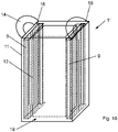
- figure 10 shows schematically another embodiment of a thermal container 1 'according to the invention in a perspective side view.
- the thermal container 1' has an outer paper bag 11 and an inner paper bag 12 located in the outer paper bag. On at least two opposite sides of the thermal container, fibrous material 9 is introduced between the inner paper bag 12 and the outer paper bag 11, which is constructed as described above.
- the inner paper bag 12 and the outer paper bag 11 can be connected to one another, including the respective fibrous material 9 .
- Carrying handles 14 are provided on an upper side of the thermal container 1'.
- suitable closure means can be provided on the insulated container 1'.
- the thermal container 1 ′ can have a block base 19 , but it can also be designed without the block base 19 .
- the fibrous material 9 used was pulp, preferably creped or non-creped or embossed tissue, for example recycled cellulose wadding from selected waste paper qualities in accordance with DIN EN 643.
- the pulp used preferably, but not necessarily, has a grammage below 20 g/m 2 .
- a wet pulping process and a removal of non-paper components can have been carried out on the fibrous material 9, but without additional bleaching, but these steps are optional.
- the respectively selected fibrous material such as tissue paper
- the respectively selected fibrous material can be guided through a calender having counter-rotating rollers, with at least one of the rollers having a surface structure.
- the embossing can also be introduced into the fibrous material 9 by one or more stamps.
- At least one embossing roller or at least one embossing stamp with a raised surface structure, such as knobs and/or ribs and/or other profiles, is preferably used here.
Landscapes
- Engineering & Computer Science (AREA)
- Mechanical Engineering (AREA)
- Packages (AREA)
Applications Claiming Priority (1)
| Application Number | Priority Date | Filing Date | Title |
|---|---|---|---|
| DE202020106559.9U DE202020106559U1 (de) | 2020-11-16 | 2020-11-16 | Thermobehältnis |
Publications (3)
| Publication Number | Publication Date |
|---|---|
| EP4001164A1 true EP4001164A1 (fr) | 2022-05-25 |
| EP4001164C0 EP4001164C0 (fr) | 2023-06-07 |
| EP4001164B1 EP4001164B1 (fr) | 2023-06-07 |
Family
ID=78032358
Family Applications (1)
| Application Number | Title | Priority Date | Filing Date |
|---|---|---|---|
| EP21196919.1A Active EP4001164B1 (fr) | 2020-11-16 | 2021-09-15 | Récipient thermique |
Country Status (3)
| Country | Link |
|---|---|
| EP (1) | EP4001164B1 (fr) |
| DE (1) | DE202020106559U1 (fr) |
| PL (1) | PL4001164T3 (fr) |
Families Citing this family (1)
| Publication number | Priority date | Publication date | Assignee | Title |
|---|---|---|---|---|
| DE102022111884B4 (de) | 2022-05-12 | 2024-05-29 | FRESH!PACKING Gmbh | Tragetasche |
Citations (8)
| Publication number | Priority date | Publication date | Assignee | Title |
|---|---|---|---|---|
| DE7836403U1 (de) | 1978-12-08 | 1979-03-08 | Goetze Nord West Papierwerk | Transportverpackung |
| WO2003066435A2 (fr) | 2002-02-08 | 2003-08-14 | Graphic Packaging International, Inc. | Emballage isolant reagissant aux micro-ondes |
| EP1382542A1 (fr) * | 2002-07-15 | 2004-01-21 | RPFI-Verpakkingen B.V. | Sac en matière plastique isolante thermiquement |
| DE102005021187A1 (de) | 2005-05-03 | 2006-11-16 | Radl, Bernd, Dr. | Alcopop-Umverpackung |
| US20070251942A1 (en) | 2006-04-27 | 2007-11-01 | Cole Lorin R | Microwave energy interactive food package |
| US20180162597A1 (en) * | 2016-12-09 | 2018-06-14 | Vericool, Inc. | Compostable envelope |
| CN210285174U (zh) * | 2019-07-23 | 2020-04-10 | 福建省凯安包装科技有限公司 | 一种便于手动封口的pp包装自立袋 |
| DE202019104350U1 (de) | 2019-08-07 | 2020-11-10 | Profümed Karlheinz Lohr e. K. | Thermobehältnis |
Family Cites Families (1)
| Publication number | Priority date | Publication date | Assignee | Title |
|---|---|---|---|---|
| DE102017111861A1 (de) | 2017-05-31 | 2018-12-06 | FRESH!PACKING Gmbh | Transportverpackung für temperatursensible Produkte |
-
2020
- 2020-11-16 DE DE202020106559.9U patent/DE202020106559U1/de active Active
-
2021
- 2021-09-15 EP EP21196919.1A patent/EP4001164B1/fr active Active
- 2021-09-15 PL PL21196919.1T patent/PL4001164T3/pl unknown
Patent Citations (8)
| Publication number | Priority date | Publication date | Assignee | Title |
|---|---|---|---|---|
| DE7836403U1 (de) | 1978-12-08 | 1979-03-08 | Goetze Nord West Papierwerk | Transportverpackung |
| WO2003066435A2 (fr) | 2002-02-08 | 2003-08-14 | Graphic Packaging International, Inc. | Emballage isolant reagissant aux micro-ondes |
| EP1382542A1 (fr) * | 2002-07-15 | 2004-01-21 | RPFI-Verpakkingen B.V. | Sac en matière plastique isolante thermiquement |
| DE102005021187A1 (de) | 2005-05-03 | 2006-11-16 | Radl, Bernd, Dr. | Alcopop-Umverpackung |
| US20070251942A1 (en) | 2006-04-27 | 2007-11-01 | Cole Lorin R | Microwave energy interactive food package |
| US20180162597A1 (en) * | 2016-12-09 | 2018-06-14 | Vericool, Inc. | Compostable envelope |
| CN210285174U (zh) * | 2019-07-23 | 2020-04-10 | 福建省凯安包装科技有限公司 | 一种便于手动封口的pp包装自立袋 |
| DE202019104350U1 (de) | 2019-08-07 | 2020-11-10 | Profümed Karlheinz Lohr e. K. | Thermobehältnis |
Also Published As
| Publication number | Publication date |
|---|---|
| EP4001164C0 (fr) | 2023-06-07 |
| DE202020106559U1 (de) | 2022-02-18 |
| EP4001164B1 (fr) | 2023-06-07 |
| PL4001164T3 (pl) | 2023-10-23 |
Similar Documents
| Publication | Publication Date | Title |
|---|---|---|
| DE69320345T2 (de) | Schale zum aufnehmen von nahrungsmitteln und verfahren zu ihrer herstellung | |
| EP3772472B1 (fr) | Récipient thermique | |
| DE102011016500A1 (de) | Isoliertüte | |
| DE69800128T2 (de) | Verpacken einer materialbahn | |
| EP3049739B1 (fr) | Corps d'isolation sous vide entouré d'une feuille | |
| EP1453744A1 (fr) | Emballage et outil de scellage pour la fabrication d'un tel emballage | |
| DE60006382T2 (de) | Verfahren zum verpacken von produkten | |
| EP4001164B1 (fr) | Récipient thermique | |
| EP0481996A1 (fr) | Barquette pour emballages destines a la vente de produits alimentaires. | |
| EP4134329B1 (fr) | Récipient thermique | |
| EP0867379B1 (fr) | Sachet pour denrées alimentaires | |
| WO1991018807A1 (fr) | Corps d'emballage | |
| DE3637867C2 (fr) | ||
| EP0905032B1 (fr) | Flan et récipient construit à partir de ce flan ainsi qu'appareil pour sa fabrication | |
| EP3925904B1 (fr) | Récipient thermique | |
| DE1927215A1 (de) | Verpackung fuer grosse flache und flexible Gegenstaende sowie Verfahren zum Falten und Verpacken derselben | |
| EP3892565B1 (fr) | Sac, en particulier sac en matière plastique, pour capsules de café usagées | |
| EP3617085A1 (fr) | Sac, en particulier sac d'expédition pour capsules de café usées, procédé de collecte et de recyclage de capsules café usées ainsi qu'utilisation du sac pour la collecte et l'expédition des capsules de café usées | |
| EP3250099A1 (fr) | Couvercle pour plats | |
| DE4339332A1 (de) | Polsterkörper | |
| WO2025109016A1 (fr) | Emballage isolant et son procédé de production | |
| EP3045405B1 (fr) | Sachet en matière plastique et poche en matière plastique, notamment pour la vente par correspondance en ligne | |
| EP1604913B1 (fr) | Emballage pour produit alimentaire | |
| EP3630631A1 (fr) | Emballage pour snacks et repas | |
| DE1901509C3 (de) | Mit einem Einsatz versehener Beutel als Verpackung für empfindliche Gegenstände |
Legal Events
| Date | Code | Title | Description |
|---|---|---|---|
| PUAI | Public reference made under article 153(3) epc to a published international application that has entered the european phase |
Free format text: ORIGINAL CODE: 0009012 |
|
| STAA | Information on the status of an ep patent application or granted ep patent |
Free format text: STATUS: REQUEST FOR EXAMINATION WAS MADE |
|
| 17P | Request for examination filed |
Effective date: 20220412 |
|
| AK | Designated contracting states |
Kind code of ref document: A1 Designated state(s): AL AT BE BG CH CY CZ DE DK EE ES FI FR GB GR HR HU IE IS IT LI LT LU LV MC MK MT NL NO PL PT RO RS SE SI SK SM TR |
|
| GRAP | Despatch of communication of intention to grant a patent |
Free format text: ORIGINAL CODE: EPIDOSNIGR1 |
|
| STAA | Information on the status of an ep patent application or granted ep patent |
Free format text: STATUS: GRANT OF PATENT IS INTENDED |
|
| INTG | Intention to grant announced |
Effective date: 20221219 |
|
| GRAS | Grant fee paid |
Free format text: ORIGINAL CODE: EPIDOSNIGR3 |
|
| GRAA | (expected) grant |
Free format text: ORIGINAL CODE: 0009210 |
|
| STAA | Information on the status of an ep patent application or granted ep patent |
Free format text: STATUS: THE PATENT HAS BEEN GRANTED |
|
| AK | Designated contracting states |
Kind code of ref document: B1 Designated state(s): AL AT BE BG CH CY CZ DE DK EE ES FI FR GB GR HR HU IE IS IT LI LT LU LV MC MK MT NL NO PL PT RO RS SE SI SK SM TR |
|
| REG | Reference to a national code |
Ref country code: GB Ref legal event code: FG4D Free format text: NOT ENGLISH |
|
| REG | Reference to a national code |
Ref country code: CH Ref legal event code: EP Ref country code: AT Ref legal event code: REF Ref document number: 1574391 Country of ref document: AT Kind code of ref document: T Effective date: 20230615 Ref country code: DE Ref legal event code: R096 Ref document number: 502021000803 Country of ref document: DE |
|
| U01 | Request for unitary effect filed |
Effective date: 20230619 |
|
| U07 | Unitary effect registered |
Designated state(s): AT BE BG DE DK EE FI FR IT LT LU LV MT NL PT SE SI Effective date: 20230626 |
|
| REG | Reference to a national code |
Ref country code: LT Ref legal event code: MG9D |
|
| U20 | Renewal fee for the european patent with unitary effect paid |
Year of fee payment: 3 Effective date: 20230908 |
|
| PG25 | Lapsed in a contracting state [announced via postgrant information from national office to epo] |
Ref country code: NO Free format text: LAPSE BECAUSE OF FAILURE TO SUBMIT A TRANSLATION OF THE DESCRIPTION OR TO PAY THE FEE WITHIN THE PRESCRIBED TIME-LIMIT Effective date: 20230907 Ref country code: ES Free format text: LAPSE BECAUSE OF FAILURE TO SUBMIT A TRANSLATION OF THE DESCRIPTION OR TO PAY THE FEE WITHIN THE PRESCRIBED TIME-LIMIT Effective date: 20230607 |
|
| PG25 | Lapsed in a contracting state [announced via postgrant information from national office to epo] |
Ref country code: RS Free format text: LAPSE BECAUSE OF FAILURE TO SUBMIT A TRANSLATION OF THE DESCRIPTION OR TO PAY THE FEE WITHIN THE PRESCRIBED TIME-LIMIT Effective date: 20230607 Ref country code: HR Free format text: LAPSE BECAUSE OF FAILURE TO SUBMIT A TRANSLATION OF THE DESCRIPTION OR TO PAY THE FEE WITHIN THE PRESCRIBED TIME-LIMIT Effective date: 20230607 Ref country code: GR Free format text: LAPSE BECAUSE OF FAILURE TO SUBMIT A TRANSLATION OF THE DESCRIPTION OR TO PAY THE FEE WITHIN THE PRESCRIBED TIME-LIMIT Effective date: 20230908 |
|
| PG25 | Lapsed in a contracting state [announced via postgrant information from national office to epo] |
Ref country code: SK Free format text: LAPSE BECAUSE OF FAILURE TO SUBMIT A TRANSLATION OF THE DESCRIPTION OR TO PAY THE FEE WITHIN THE PRESCRIBED TIME-LIMIT Effective date: 20230607 |
|
| PG25 | Lapsed in a contracting state [announced via postgrant information from national office to epo] |
Ref country code: IS Free format text: LAPSE BECAUSE OF FAILURE TO SUBMIT A TRANSLATION OF THE DESCRIPTION OR TO PAY THE FEE WITHIN THE PRESCRIBED TIME-LIMIT Effective date: 20231007 |
|
| PG25 | Lapsed in a contracting state [announced via postgrant information from national office to epo] |
Ref country code: SM Free format text: LAPSE BECAUSE OF FAILURE TO SUBMIT A TRANSLATION OF THE DESCRIPTION OR TO PAY THE FEE WITHIN THE PRESCRIBED TIME-LIMIT Effective date: 20230607 Ref country code: SK Free format text: LAPSE BECAUSE OF FAILURE TO SUBMIT A TRANSLATION OF THE DESCRIPTION OR TO PAY THE FEE WITHIN THE PRESCRIBED TIME-LIMIT Effective date: 20230607 Ref country code: RO Free format text: LAPSE BECAUSE OF FAILURE TO SUBMIT A TRANSLATION OF THE DESCRIPTION OR TO PAY THE FEE WITHIN THE PRESCRIBED TIME-LIMIT Effective date: 20230607 Ref country code: IS Free format text: LAPSE BECAUSE OF FAILURE TO SUBMIT A TRANSLATION OF THE DESCRIPTION OR TO PAY THE FEE WITHIN THE PRESCRIBED TIME-LIMIT Effective date: 20231007 Ref country code: CZ Free format text: LAPSE BECAUSE OF FAILURE TO SUBMIT A TRANSLATION OF THE DESCRIPTION OR TO PAY THE FEE WITHIN THE PRESCRIBED TIME-LIMIT Effective date: 20230607 |
|
| REG | Reference to a national code |
Ref country code: DE Ref legal event code: R097 Ref document number: 502021000803 Country of ref document: DE |
|
| PLBE | No opposition filed within time limit |
Free format text: ORIGINAL CODE: 0009261 |
|
| STAA | Information on the status of an ep patent application or granted ep patent |
Free format text: STATUS: NO OPPOSITION FILED WITHIN TIME LIMIT |
|
| 26N | No opposition filed |
Effective date: 20240308 |
|
| PG25 | Lapsed in a contracting state [announced via postgrant information from national office to epo] |
Ref country code: MC Free format text: LAPSE BECAUSE OF FAILURE TO SUBMIT A TRANSLATION OF THE DESCRIPTION OR TO PAY THE FEE WITHIN THE PRESCRIBED TIME-LIMIT Effective date: 20230607 |
|
| REG | Reference to a national code |
Ref country code: IE Ref legal event code: MM4A |
|
| PG25 | Lapsed in a contracting state [announced via postgrant information from national office to epo] |
Ref country code: IE Free format text: LAPSE BECAUSE OF NON-PAYMENT OF DUE FEES Effective date: 20230915 |
|
| PG25 | Lapsed in a contracting state [announced via postgrant information from national office to epo] |
Ref country code: IE Free format text: LAPSE BECAUSE OF NON-PAYMENT OF DUE FEES Effective date: 20230915 |
|
| U20 | Renewal fee for the european patent with unitary effect paid |
Year of fee payment: 4 Effective date: 20240705 |
|
| REG | Reference to a national code |
Ref country code: CH Ref legal event code: PL |
|
| PG25 | Lapsed in a contracting state [announced via postgrant information from national office to epo] |
Ref country code: CH Free format text: LAPSE BECAUSE OF NON-PAYMENT OF DUE FEES Effective date: 20240930 |
|
| PG25 | Lapsed in a contracting state [announced via postgrant information from national office to epo] |
Ref country code: CY Free format text: LAPSE BECAUSE OF FAILURE TO SUBMIT A TRANSLATION OF THE DESCRIPTION OR TO PAY THE FEE WITHIN THE PRESCRIBED TIME-LIMIT; INVALID AB INITIO Effective date: 20210915 |
|
| U20 | Renewal fee for the european patent with unitary effect paid |
Year of fee payment: 5 Effective date: 20250702 |
|
| PG25 | Lapsed in a contracting state [announced via postgrant information from national office to epo] |
Ref country code: HU Free format text: LAPSE BECAUSE OF FAILURE TO SUBMIT A TRANSLATION OF THE DESCRIPTION OR TO PAY THE FEE WITHIN THE PRESCRIBED TIME-LIMIT; INVALID AB INITIO Effective date: 20210915 |
|
| PGFP | Annual fee paid to national office [announced via postgrant information from national office to epo] |
Ref country code: PL Payment date: 20250702 Year of fee payment: 5 |
|
| PGFP | Annual fee paid to national office [announced via postgrant information from national office to epo] |
Ref country code: GB Payment date: 20250923 Year of fee payment: 5 |
|
| PG25 | Lapsed in a contracting state [announced via postgrant information from national office to epo] |
Ref country code: TR Free format text: LAPSE BECAUSE OF FAILURE TO SUBMIT A TRANSLATION OF THE DESCRIPTION OR TO PAY THE FEE WITHIN THE PRESCRIBED TIME-LIMIT Effective date: 20230607 |