EP4001577B1 - Joint d'étanchéité automatique doté d'un ressort de surcharge en élastomère - Google Patents
Joint d'étanchéité automatique doté d'un ressort de surcharge en élastomère Download PDFInfo
- Publication number
- EP4001577B1 EP4001577B1 EP20209592.3A EP20209592A EP4001577B1 EP 4001577 B1 EP4001577 B1 EP 4001577B1 EP 20209592 A EP20209592 A EP 20209592A EP 4001577 B1 EP4001577 B1 EP 4001577B1
- Authority
- EP
- European Patent Office
- Prior art keywords
- push rod
- spring
- seal
- trigger
- sealing strip
- Prior art date
- Legal status (The legal status is an assumption and is not a legal conclusion. Google has not performed a legal analysis and makes no representation as to the accuracy of the status listed.)
- Active
Links
Images






Classifications
-
- E—FIXED CONSTRUCTIONS
- E06—DOORS, WINDOWS, SHUTTERS, OR ROLLER BLINDS IN GENERAL; LADDERS
- E06B—FIXED OR MOVABLE CLOSURES FOR OPENINGS IN BUILDINGS, VEHICLES, FENCES OR LIKE ENCLOSURES IN GENERAL, e.g. DOORS, WINDOWS, BLINDS, GATES
- E06B7/00—Special arrangements or measures in connection with doors or windows
- E06B7/16—Sealing arrangements on wings or parts co-operating with the wings
- E06B7/18—Sealing arrangements on wings or parts co-operating with the wings by means of movable edgings, e.g. draught sealings additionally used for bolting, e.g. by spring force or with operating lever
- E06B7/20—Sealing arrangements on wings or parts co-operating with the wings by means of movable edgings, e.g. draught sealings additionally used for bolting, e.g. by spring force or with operating lever automatically withdrawn when the wing is opened, e.g. by means of magnetic attraction, a pin or an inclined surface, especially for sills
- E06B7/215—Sealing arrangements on wings or parts co-operating with the wings by means of movable edgings, e.g. draught sealings additionally used for bolting, e.g. by spring force or with operating lever automatically withdrawn when the wing is opened, e.g. by means of magnetic attraction, a pin or an inclined surface, especially for sills with sealing strip being moved to a retracted position by elastic means, e.g. springs
Definitions
- Coil springs are provided for the seals disclosed.
- Coil springs have a substantially circular cross-section. In order for them to be arranged in the seal, space must be provided according to the diameter. This restricts the designer of the very narrow seals from the application EP 19 166 220.4 and from the document EP 3 699 384 A1 in the construction.
- a seal with the features mentioned above is also described in the application EP 20 154 981.3
- the seal disclosed in the application uses return springs and/or overload springs that have a wave, triangular, sawtooth or similar curved profile. These springs can be made very narrow.
- the object of the invention was to propose an alternative to springs with a wave, triangular, sawtooth or similar curved profile, without resorting to coil springs, for which standardized articles can be used.
- the overload spring is a spring made of an elastomer.
- the return spring can also be a spring made of an elastomer.
- the overload spring and also the return spring can be a ring, in particular an O-ring, which can be purchased inexpensively in large quantities.
- the rod may have at least one projection, a nose, a hook or a similar element on which the return spring and/or the overload spring can be hooked.
- the return spring can be attached directly or indirectly to the holding means.
- the overload spring can be attached directly or indirectly to an element of the movement mechanism.
- the overload spring fixes the element of the movement mechanism relative to the rod as long as the sealing strip can be moved without hitting an obstacle.
- the movement mechanism can be a scissor mechanism having a first scissor element rotatably mounted on the holding means and a second scissor element rotatably mounted on the first scissor element and at least rotatably mounted on the sealing strip.
- the movement mechanism can have a bearing element relative to which the rod can be linearly displaced and on which the second scissor element is also rotatably mounted and on which the overload spring is suspended.
- the second scissor element can have a first gap into which the bearing element can be inserted, in particular when no overload is present.
- the bearing element can have at least one projection, a nose, a hook or a similar element on which the overload spring is suspended.
- the second scissor element can have a second gap or a window through which the rod is guided.
- first scissor element prefferably has a gap into which the rod dips in the release position of the sealing strip. Then, in the release position, the rod and the first scissor element are positioned relative to one another.
- the movement mechanism could also comprise a leaf spring or an elastic rod having a first end is connected to the holding means and its second end is connected indirectly via the overload spring or to the rod.
- the leaf spring or the elastic rod can be bent by moving the rod relative to the holding means. This allows the area between the two ends of the leaf spring or the elastic rod to be deflected.
- the sealing strip can be attached to this deflected area and can be moved from the release position into the sealing position by deflecting it.
- the connection between the second end of the leaf spring or the elastic rod and the rod is made in such a way that the second end is pulled onto the rod as long as the sealing strip encounters resistance when the sealing strip is moved from the release position into the sealing position.
- the holding means can be a housing.
- the holding means can be a module carrier of a modular seal, in which each module has a movement mechanism and a rod.
- Each module can have a return spring and/or an overload spring.
- the seal according to the invention shown is a seal that can be used as an automatic floor seal in hinged doors.
- the seal can also be used on other doors, for example sliding doors, or at other points on a door, for example at the top of the door. This may require modifications, but these do not affect the properties that distinguish the seal from known seals.
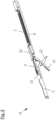
- the seal has a housing 1 and a sealing strip 2, 3.
- the sealing strip 2, 3 has a retaining rail 2 and a sealing profile 3 made of an elastomer.
- the sealing strip 2, 3 is connected to the housing 1 via a movement mechanism 4.
- the movement mechanism is connected via push rods 5, 5a to a trigger 6, which projects beyond the housing 1 on one end face.
- a stop surface 61 of the trigger 6 By pressing on a stop surface 61 of the trigger 6, the sealing strip 2, 3 can be moved from a release position to a sealing position. If the trigger 6 is released, the sealing strip is moved into the release position by springs 7 and held in this release position.
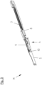
- the movement mechanisms are in modules M, see Figures 1 to 11 , the seal is provided.
- the seal shown has two Modules M. Especially for longer seals, more than two modules can be provided.
- each of the modules has a module carrier 8, one of the push rods 5 and one of the springs 7.
- the module carrier 8 is fastened in the housing 1. In the fastened state, it cannot be moved relative to the housing 1.
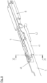
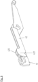
- the movement mechanism 4 of each module M is a scissor mechanism with a first scissor element 41 and a second scissor element 42.
- the two scissor elements are connected to each other via a pivot bearing L.
- a first end of the first scissor element 41 is rotatably connected to the module carrier 8 of each module M.
- the first scissor element has two outward-facing pivot pins that engage in recesses in the module carrier 8.
- a second end of the first scissor element 41 is rotatably and slidably mounted in or on the holding rail 2 of the sealing strip 2, 3. This second end has a slot into which the rod 5 of the module is inserted in the release position.
- a first end of the second scissor element 42 is rotatably connected to the push rod 5 of the module M.
- a second end of the second scissor element 42 is rotatably connected to the holding rail 2 of the sealing strip 2, 3.
- a pin is provided on the second end, which engages in a channel of the holding rail 2.
- the second scissor element 42 has a window through which the push rod 5 is guided.
- the scissor mechanism 41, 42 itself is in the European patent application 19 166 220.4 described.
- the module carrier 8 has a guide element 81 which forms a guide channel in which the push rod 5 is guided so that it can be moved linearly relative to the module carrier 8 and the housing 1.
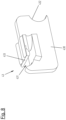
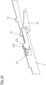
- An axis 421 of the second scissor element 42 is accommodated in a recess 432 with a semicircular cross-section of a bearing element 43 for the rotatable connection between the second scissor element and the push rod 5.
- the bearing element 43 is inserted into a gap between two guide elements 422 of the second scissor element. These two guide elements 422 not only serve to position the bearing element 43.
- the push rod 5 is also guided between these guide elements 422.
- the guide elements 422 with circular arc-shaped contours roll on an inner side of the housing of the seal when the movement mechanism 4 is actuated.
- the bearing element 43 has a protruding nose 433 through which a channel 431 is formed. A section of an O-ring 9 is suspended behind this nose 433.
- the suspended section of the O-ring 9 lies in the channel 431.
- the O-ring 9 is also suspended on a nose 52 of the push rod 5.
- the O-ring 9 is stretched between the noses 433, 52 and thus pulls the bearing element 43 against the rod.
- the axis 421 of the second scissor element arranged in the recess 432 of the bearing element 43 is thereby also pressed into a bulge in the push rod 5, which is formed by a further nose 51 of the rod is formed.
- the axis 421 is thereby mounted between the bearing element 43 and the push rod 5 as long as the force of the O-ring 9 is sufficiently large to pull the bearing element 43 against the push rod 5.
- the O-ring 9 is the overload spring which prevents damage to the seal, in particular to the movement mechanism, if the sealing strip 2, 3 cannot perform any or sufficient stroke when the seal is actuated by introducing a force into the trigger and into the push rod n5, 5a. If the bearing for the axis 421 were provided in a recess in the push rod 5, in a case in which the sealing strip 2, 3 cannot be moved further in the direction of the sealing position because it has encountered resistance, the push rod 5 could also not be moved despite the continued introduction of force into the trigger 6. The continued introduction of force can then lead to damage to the seal.
- the bearing element 43 can lift off the push rod 5.
- the axis 421 of the second scissor element then also detaches from the push rod 5 and is pressed further into the recess 432 by the force of the resistance that opposes the sealing strip.
- the push rod 5 can be moved further by the force introduced via the trigger 6 without any force being transmitted to the movement mechanism.
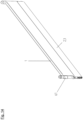
- the push rods 5 of the modules M are coupled to one another via the push rod 5a.
- the coupling of the push rods 5 of the modules M with the push rod 5a takes place in guide elements 10 which are fastened in the housing. These have a guide channel in which the ends of the push rods 5 or the push rod 5a are guided.
- the push rods 5, 5a butt against each other in the guide channel.
- the push rods 5, 5a are not attached to each other. Therefore, only a compressive force and not a tensile force can be transmitted between the push rods 5, 5a.
- the guide elements 10 are so long that the joint between the push rods 5, 5a remains in the guide channel even if the push rods 5, 5a are moved when the seal is actuated.
- the push rod of the module 5, which is arranged next to the trigger 6, is connected to the trigger on the trigger side.
- This connection is also provided in a guide element 10.
- the connection is a snap connection that can be subjected to pressure and, within certain limits, to tensile stress. Because the connection can also be subjected to tensile stress within certain limits, it is possible to transfer a compressive force exerted on the trigger 6 to actuate the seal to the push rods 5, 5a and the movement mechanisms 4. At the same time, the trigger 6 is held in the housing 1 by the snap connection and cannot fall off the rest of the seal. However, if a tensile force exerted on the trigger 6 exceeds a certain limit, the snap connection is released and the trigger 6 can be removed from the housing 1. This may be necessary if the length of the trigger 6 is to be adjusted.
- the first component 61 has a stop surface at a first end located outside the housing 1, with which the trigger 6 can strike against a door frame when the door is closed. This transfers a pressure force to the trigger 6, which causes the sealing strip 2, 3 to move from the release position to the sealing position.
- the first component 61 of the trigger 6 has a threaded hole.
- the second component 62 of the trigger 6 has a threaded pin at one end facing the first component 61.
- This threaded pin has a T-shaped cross-sectional profile. Only the outer sides of the pin lie on a circular line and have threads that interact with the thread of the threaded hole in the first component 61.
- the length of the trigger 6 can be determined by selecting the screwing depth of the threaded pin into the threaded hole.
- the push rod 5 of each module M has a recess in which the spring 7 is accommodated.
- This spring 7 has a first end which is connected to the push rod 5 of the module M.
- a second end of the spring 7 of the module M is connected to the module carrier 8 of the module M.
- the attachment point of the spring 7 on the module carrier 8 is in front of the attachment point of the spring 7 on the push rod 5 in the direction of movement of the push rod 5 when actuated by pressing the trigger 6.
- the spring 7 is a tension spring.
- the sealing strip is moved from the release position to the sealing position by actuating the seal by pressing the trigger 6, whereby the sealing strip 2, 3 is moved parallel to the housing 1 in the direction out of the housing 1.
- the springs 7 can relax and contract.
- the movement mechanisms 4 are then operated in the opposite direction and the Sealing strip 2, 3 is raised and held in the raised position by the springs 7.
Landscapes
- Engineering & Computer Science (AREA)
- Civil Engineering (AREA)
- Structural Engineering (AREA)
- Specific Sealing Or Ventilating Devices For Doors And Windows (AREA)
Claims (11)
- Joint d'étanchéité automatique pour une porte- avec un moyen de retenue (8),- avec une bande d'étanchéité (2, 3) qui présente un profil d'étanchéité (3),- avec un déclencheur (6) pour introduire une force dans le joint d'étanchéité pour déplacer la bande d'étanchéité (2, 3),- avec une tige de poussée (5) et avec au moins un mécanisme (4) pour transmettre un mouvement du déclencheur (6) à la bande d'étanchéité (2, 3) qui est mobile au moyen du mécanisme de mouvement (4) d'une position d'étanchéité à une position de libération et inversement,- avec au moins un ressort de surcharge (9),- dans lequel la tige de poussée (5) est couplée au déclencheur (6) pour transmettre le mouvement du déclencheur (6) à la tige de poussée (5),- dans lequel la tige de poussée (5) est couplée au mécanisme de mouvement (4) par l'intermédiaire du ressort de surcharge (9),caractérisé en ce que
le ressort de surcharge (9) est un ressort en élastomère. - Joint d'étanchéité selon la revendication 1, caractérisé en ce que le ressort de surcharge (9) est un anneau, en particulier un joint torique.
- Joint d'étanchéité selon la revendication 1 ou 2, caractérisé en ce que la tige de poussée (5) présente au moins une saillie, un ergot (52), un crochet ou un élément similaire sur lequel le ressort de surcharge (9) est accroché.
- Joint d'étanchéité selon l'une quelconque des revendications 1 à 3, caractérisé en ce que le ressort de surcharge (9) est accroché directement ou indirectement à un élément (43) du mécanisme de mouvement (4).
- Joint d'étanchéité selon l'une quelconque des revendications 1 à 4, caractérisé en ce que le mécanisme de mouvement (4) est un mécanisme de ciseaux (41, 42) qui présente un premier élément de ciseaux (41) monté en rotation sur le moyen de retenue (8) et un second élément de ciseaux (42) monté en rotation sur le premier élément de ciseaux (41) et au moins en rotation sur la bande d'étanchéité (2, 3).
- Joint d'étanchéité selon les revendications 4 et 5, caractérisé en ce que le mécanisme de mouvement (4) présente un élément de palier (43) par rapport auquel la tige de poussée (5) est déplaçable linéairement et sur lequel le second élément de ciseaux (42) est également monté de manière rotative et auquel le ressort de surcharge (9) est accroché.
- Joint d'étanchéité selon la revendication 6, caractérisé en ce que l'élément de palier (43) est inséré dans une première fente du second élément de ciseaux (42).
- Joint d'étanchéité selon la revendication 6 ou 7, caractérisé en ce que l'élément de palier (43) présente au moins une saillie, un ergot (433), un crochet ou un élément similaire sur lequel le ressort de surcharge (9) est accroché.
- Joint d'étanchéité selon l'une quelconque des revendications 5 à 8, caractérisé en ce que le second élément de ciseaux (42) présente une seconde fente ou une fenêtre à travers laquelle la tige de poussée (5) est guidée.
- Joint d'étanchéité selon l'une quelconque des revendications 6 à 9, caractérisé en ce que le premier élément de ciseaux (41) présente une fente dans laquelle la tige de poussée (5) est insérée dans la position de libération de la bande d'étanchéité (2, 3).
- Joint d'étanchéité selon l'une quelconque des revendications 5 à 10, caractérisé en ce que le joint d'étanchéité présente un ressort de rappel, dans lequel la tige de poussée (5) est connectée au moins indirectement au moyen de retenue par l'intermédiaire du ressort de rappel,
caractérisé en ce que
le ressort de rappel est un ressort en élastomère.
Priority Applications (1)
| Application Number | Priority Date | Filing Date | Title |
|---|---|---|---|
| EP20209592.3A EP4001577B1 (fr) | 2020-11-24 | 2020-11-24 | Joint d'étanchéité automatique doté d'un ressort de surcharge en élastomère |
Applications Claiming Priority (1)
| Application Number | Priority Date | Filing Date | Title |
|---|---|---|---|
| EP20209592.3A EP4001577B1 (fr) | 2020-11-24 | 2020-11-24 | Joint d'étanchéité automatique doté d'un ressort de surcharge en élastomère |
Publications (2)
| Publication Number | Publication Date |
|---|---|
| EP4001577A1 EP4001577A1 (fr) | 2022-05-25 |
| EP4001577B1 true EP4001577B1 (fr) | 2024-11-06 |
Family
ID=73597822
Family Applications (1)
| Application Number | Title | Priority Date | Filing Date |
|---|---|---|---|
| EP20209592.3A Active EP4001577B1 (fr) | 2020-11-24 | 2020-11-24 | Joint d'étanchéité automatique doté d'un ressort de surcharge en élastomère |
Country Status (1)
| Country | Link |
|---|---|
| EP (1) | EP4001577B1 (fr) |
Family Cites Families (4)
| Publication number | Priority date | Publication date | Assignee | Title |
|---|---|---|---|---|
| US16341A (en) * | 1857-01-06 | Weather-strip for doors | ||
| US384003A (en) * | 1888-06-05 | Joseph thompson and john o | ||
| FR802747A (fr) * | 1935-03-11 | 1936-09-14 | Dispositif empêchant les courants d'air de passer au-dessous des portes, fenêtres, etc. | |
| DK3699384T3 (da) * | 2019-02-20 | 2022-10-24 | Athmer Ohg | Tætning med en sænkbar tætningsliste, der kan sænkes ved hjælp af en sænkningsmekanisme, der kan betjenes af en udløser |
-
2020
- 2020-11-24 EP EP20209592.3A patent/EP4001577B1/fr active Active
Also Published As
| Publication number | Publication date |
|---|---|
| EP4001577A1 (fr) | 2022-05-25 |
Similar Documents
| Publication | Publication Date | Title |
|---|---|---|
| EP2085559B1 (fr) | Dispositif d'étanchéité abaissable | |
| EP2474698B1 (fr) | Dispositif d'étanchéité doté d'un profil d'étanchéité et d'un mécanisme destiné au déplacement du profil d'étanchéité lors de l'actionnement du mécanisme | |
| EP3284898B1 (fr) | Joint comprenant une bande d'étanchéité pouvant s'abaisser à l'aide de deux mécanismes à ciseaux | |
| DE10347528B3 (de) | Türöffner | |
| DE102005042510A1 (de) | Außenliegende mechanische Verriegelung für einen Linearaktuator | |
| EP2634350B1 (fr) | Joint amovible, notamment joint de porte coulissante | |
| DE102004011880A1 (de) | Schließblech für Fenster oder Fenstertüren | |
| DE102016202377A1 (de) | Beschlaganordnung zur Anbindung eines schieb- und kippbaren Flügels | |
| EP4012141B1 (fr) | Console de montage pour un actionneur de porte | |
| EP3868994B1 (fr) | Joint d'étanchéité pourvu de modules comportant un mécanisme d'abaissement | |
| EP2725173A2 (fr) | Serrure d'encliquetage, notamment pour le verrouillage supplémentaire d'une porte, d'un portail ou d'une fenêtre | |
| EP4001577B1 (fr) | Joint d'étanchéité automatique doté d'un ressort de surcharge en élastomère | |
| EP1420136B1 (fr) | Crémone pour le battant semi-fixe d'une fenêtre ou porte à deux battants sans montant central, et procédé de montage automatique ou semi-automatique d'une crémone | |
| DE3520861A1 (de) | Rueckdruecksperre an treibstangenbeschlaegen, insbesondere schluesselbetaetigbaren treibstangenschloessern | |
| DE19646982A1 (de) | Beschlag für ein Fenster | |
| DE2257744A1 (de) | Schloss zum verriegeln von tueren oder fenstern | |
| EP3725992B1 (fr) | Entraînement | |
| EP2672046A2 (fr) | Agencement de rail de guidage | |
| DE20109265U1 (de) | Verriegelungsvorrichtung | |
| DE202017101426U1 (de) | Werkzeug zum Entfernen und Anbringen von Rohrschellen | |
| DE102020109074A1 (de) | Vorrichtung zur unterstützung des schliessens und öffnens eines hebe-schiebeelements | |
| EP3599335B1 (fr) | Joint d'étanchéité abaissable, en particulier pour portes coulissantes | |
| EP4386170B1 (fr) | Joint automatique pour portes ou portails coulissants | |
| EP3287577B1 (fr) | Dispositif de fermeture de porte, fenêtre ou analogue | |
| EP4276267B1 (fr) | Joint d'étanchéité, notamment pour portes coulissantes ou portes coulissantes |
Legal Events
| Date | Code | Title | Description |
|---|---|---|---|
| PUAI | Public reference made under article 153(3) epc to a published international application that has entered the european phase |
Free format text: ORIGINAL CODE: 0009012 |
|
| STAA | Information on the status of an ep patent application or granted ep patent |
Free format text: STATUS: REQUEST FOR EXAMINATION WAS MADE |
|
| 17P | Request for examination filed |
Effective date: 20220414 |
|
| AK | Designated contracting states |
Kind code of ref document: A1 Designated state(s): AL AT BE BG CH CY CZ DE DK EE ES FI FR GB GR HR HU IE IS IT LI LT LU LV MC MK MT NL NO PL PT RO RS SE SI SK SM TR |
|
| STAA | Information on the status of an ep patent application or granted ep patent |
Free format text: STATUS: EXAMINATION IS IN PROGRESS |
|
| 17Q | First examination report despatched |
Effective date: 20230215 |
|
| GRAP | Despatch of communication of intention to grant a patent |
Free format text: ORIGINAL CODE: EPIDOSNIGR1 |
|
| STAA | Information on the status of an ep patent application or granted ep patent |
Free format text: STATUS: GRANT OF PATENT IS INTENDED |
|
| INTG | Intention to grant announced |
Effective date: 20240606 |
|
| P01 | Opt-out of the competence of the unified patent court (upc) registered |
Free format text: CASE NUMBER: APP_48191/2024 Effective date: 20240821 |
|
| GRAS | Grant fee paid |
Free format text: ORIGINAL CODE: EPIDOSNIGR3 |
|
| GRAA | (expected) grant |
Free format text: ORIGINAL CODE: 0009210 |
|
| STAA | Information on the status of an ep patent application or granted ep patent |
Free format text: STATUS: THE PATENT HAS BEEN GRANTED |
|
| AK | Designated contracting states |
Kind code of ref document: B1 Designated state(s): AL AT BE BG CH CY CZ DE DK EE ES FI FR GB GR HR HU IE IS IT LI LT LU LV MC MK MT NL NO PL PT RO RS SE SI SK SM TR |
|
| REG | Reference to a national code |
Ref country code: GB Ref legal event code: FG4D Free format text: NOT ENGLISH |
|
| REG | Reference to a national code |
Ref country code: CH Ref legal event code: EP |
|
| REG | Reference to a national code |
Ref country code: DE Ref legal event code: R096 Ref document number: 502020009678 Country of ref document: DE |
|
| REG | Reference to a national code |
Ref country code: IE Ref legal event code: FG4D Free format text: LANGUAGE OF EP DOCUMENT: GERMAN |
|
| REG | Reference to a national code |
Ref country code: LT Ref legal event code: MG9D |
|
| REG | Reference to a national code |
Ref country code: NL Ref legal event code: MP Effective date: 20241106 |
|
| PG25 | Lapsed in a contracting state [announced via postgrant information from national office to epo] |
Ref country code: PT Free format text: LAPSE BECAUSE OF FAILURE TO SUBMIT A TRANSLATION OF THE DESCRIPTION OR TO PAY THE FEE WITHIN THE PRESCRIBED TIME-LIMIT Effective date: 20250306 Ref country code: HR Free format text: LAPSE BECAUSE OF FAILURE TO SUBMIT A TRANSLATION OF THE DESCRIPTION OR TO PAY THE FEE WITHIN THE PRESCRIBED TIME-LIMIT Effective date: 20241106 Ref country code: IS Free format text: LAPSE BECAUSE OF FAILURE TO SUBMIT A TRANSLATION OF THE DESCRIPTION OR TO PAY THE FEE WITHIN THE PRESCRIBED TIME-LIMIT Effective date: 20250306 |
|
| PG25 | Lapsed in a contracting state [announced via postgrant information from national office to epo] |
Ref country code: FI Free format text: LAPSE BECAUSE OF FAILURE TO SUBMIT A TRANSLATION OF THE DESCRIPTION OR TO PAY THE FEE WITHIN THE PRESCRIBED TIME-LIMIT Effective date: 20241106 Ref country code: NL Free format text: LAPSE BECAUSE OF FAILURE TO SUBMIT A TRANSLATION OF THE DESCRIPTION OR TO PAY THE FEE WITHIN THE PRESCRIBED TIME-LIMIT Effective date: 20241106 |
|
| PG25 | Lapsed in a contracting state [announced via postgrant information from national office to epo] |
Ref country code: BG Free format text: LAPSE BECAUSE OF FAILURE TO SUBMIT A TRANSLATION OF THE DESCRIPTION OR TO PAY THE FEE WITHIN THE PRESCRIBED TIME-LIMIT Effective date: 20241106 |
|
| PG25 | Lapsed in a contracting state [announced via postgrant information from national office to epo] |
Ref country code: ES Free format text: LAPSE BECAUSE OF FAILURE TO SUBMIT A TRANSLATION OF THE DESCRIPTION OR TO PAY THE FEE WITHIN THE PRESCRIBED TIME-LIMIT Effective date: 20241106 |
|
| PG25 | Lapsed in a contracting state [announced via postgrant information from national office to epo] |
Ref country code: NO Free format text: LAPSE BECAUSE OF FAILURE TO SUBMIT A TRANSLATION OF THE DESCRIPTION OR TO PAY THE FEE WITHIN THE PRESCRIBED TIME-LIMIT Effective date: 20250206 |
|
| PG25 | Lapsed in a contracting state [announced via postgrant information from national office to epo] |
Ref country code: GR Free format text: LAPSE BECAUSE OF FAILURE TO SUBMIT A TRANSLATION OF THE DESCRIPTION OR TO PAY THE FEE WITHIN THE PRESCRIBED TIME-LIMIT Effective date: 20250207 Ref country code: LV Free format text: LAPSE BECAUSE OF FAILURE TO SUBMIT A TRANSLATION OF THE DESCRIPTION OR TO PAY THE FEE WITHIN THE PRESCRIBED TIME-LIMIT Effective date: 20241106 |
|
| PG25 | Lapsed in a contracting state [announced via postgrant information from national office to epo] |
Ref country code: PL Free format text: LAPSE BECAUSE OF FAILURE TO SUBMIT A TRANSLATION OF THE DESCRIPTION OR TO PAY THE FEE WITHIN THE PRESCRIBED TIME-LIMIT Effective date: 20241106 |
|
| PG25 | Lapsed in a contracting state [announced via postgrant information from national office to epo] |
Ref country code: RS Free format text: LAPSE BECAUSE OF FAILURE TO SUBMIT A TRANSLATION OF THE DESCRIPTION OR TO PAY THE FEE WITHIN THE PRESCRIBED TIME-LIMIT Effective date: 20250206 |
|
| PG25 | Lapsed in a contracting state [announced via postgrant information from national office to epo] |
Ref country code: SM Free format text: LAPSE BECAUSE OF FAILURE TO SUBMIT A TRANSLATION OF THE DESCRIPTION OR TO PAY THE FEE WITHIN THE PRESCRIBED TIME-LIMIT Effective date: 20241106 |
|
| PG25 | Lapsed in a contracting state [announced via postgrant information from national office to epo] |
Ref country code: DK Free format text: LAPSE BECAUSE OF FAILURE TO SUBMIT A TRANSLATION OF THE DESCRIPTION OR TO PAY THE FEE WITHIN THE PRESCRIBED TIME-LIMIT Effective date: 20241106 |
|
| PG25 | Lapsed in a contracting state [announced via postgrant information from national office to epo] |
Ref country code: LU Free format text: LAPSE BECAUSE OF NON-PAYMENT OF DUE FEES Effective date: 20241124 |
|
| PG25 | Lapsed in a contracting state [announced via postgrant information from national office to epo] |
Ref country code: EE Free format text: LAPSE BECAUSE OF FAILURE TO SUBMIT A TRANSLATION OF THE DESCRIPTION OR TO PAY THE FEE WITHIN THE PRESCRIBED TIME-LIMIT Effective date: 20241106 |
|
| PG25 | Lapsed in a contracting state [announced via postgrant information from national office to epo] |
Ref country code: RO Free format text: LAPSE BECAUSE OF FAILURE TO SUBMIT A TRANSLATION OF THE DESCRIPTION OR TO PAY THE FEE WITHIN THE PRESCRIBED TIME-LIMIT Effective date: 20241106 |
|
| PG25 | Lapsed in a contracting state [announced via postgrant information from national office to epo] |
Ref country code: SK Free format text: LAPSE BECAUSE OF FAILURE TO SUBMIT A TRANSLATION OF THE DESCRIPTION OR TO PAY THE FEE WITHIN THE PRESCRIBED TIME-LIMIT Effective date: 20241106 |
|
| PG25 | Lapsed in a contracting state [announced via postgrant information from national office to epo] |
Ref country code: CZ Free format text: LAPSE BECAUSE OF FAILURE TO SUBMIT A TRANSLATION OF THE DESCRIPTION OR TO PAY THE FEE WITHIN THE PRESCRIBED TIME-LIMIT Effective date: 20241106 |
|
| PG25 | Lapsed in a contracting state [announced via postgrant information from national office to epo] |
Ref country code: IT Free format text: LAPSE BECAUSE OF FAILURE TO SUBMIT A TRANSLATION OF THE DESCRIPTION OR TO PAY THE FEE WITHIN THE PRESCRIBED TIME-LIMIT Effective date: 20241106 |
|
| REG | Reference to a national code |
Ref country code: DE Ref legal event code: R097 Ref document number: 502020009678 Country of ref document: DE |
|
| REG | Reference to a national code |
Ref country code: BE Ref legal event code: MM Effective date: 20241130 |
|
| PG25 | Lapsed in a contracting state [announced via postgrant information from national office to epo] |
Ref country code: SE Free format text: LAPSE BECAUSE OF FAILURE TO SUBMIT A TRANSLATION OF THE DESCRIPTION OR TO PAY THE FEE WITHIN THE PRESCRIBED TIME-LIMIT Effective date: 20241106 |
|
| PLBE | No opposition filed within time limit |
Free format text: ORIGINAL CODE: 0009261 |
|
| STAA | Information on the status of an ep patent application or granted ep patent |
Free format text: STATUS: NO OPPOSITION FILED WITHIN TIME LIMIT |
|
| PG25 | Lapsed in a contracting state [announced via postgrant information from national office to epo] |
Ref country code: MC Free format text: LAPSE BECAUSE OF FAILURE TO SUBMIT A TRANSLATION OF THE DESCRIPTION OR TO PAY THE FEE WITHIN THE PRESCRIBED TIME-LIMIT Effective date: 20241106 |
|
| 26N | No opposition filed |
Effective date: 20250807 |
|
| PG25 | Lapsed in a contracting state [announced via postgrant information from national office to epo] |
Ref country code: BE Free format text: LAPSE BECAUSE OF NON-PAYMENT OF DUE FEES Effective date: 20241130 |
|
| PG25 | Lapsed in a contracting state [announced via postgrant information from national office to epo] |
Ref country code: FR Free format text: LAPSE BECAUSE OF NON-PAYMENT OF DUE FEES Effective date: 20250106 |
|
| PG25 | Lapsed in a contracting state [announced via postgrant information from national office to epo] |
Ref country code: IE Free format text: LAPSE BECAUSE OF NON-PAYMENT OF DUE FEES Effective date: 20241124 |
|
| REG | Reference to a national code |
Ref country code: CH Ref legal event code: U11 Free format text: ST27 STATUS EVENT CODE: U-0-0-U10-U11 (AS PROVIDED BY THE NATIONAL OFFICE) Effective date: 20251201 |
|
| PGFP | Annual fee paid to national office [announced via postgrant information from national office to epo] |
Ref country code: DE Payment date: 20251130 Year of fee payment: 6 |
|
| PGFP | Annual fee paid to national office [announced via postgrant information from national office to epo] |
Ref country code: GB Payment date: 20251121 Year of fee payment: 6 |
|
| PGFP | Annual fee paid to national office [announced via postgrant information from national office to epo] |
Ref country code: AT Payment date: 20251120 Year of fee payment: 6 |
|
| PGFP | Annual fee paid to national office [announced via postgrant information from national office to epo] |
Ref country code: CH Payment date: 20251201 Year of fee payment: 6 |
|
| PG25 | Lapsed in a contracting state [announced via postgrant information from national office to epo] |
Ref country code: HU Free format text: LAPSE BECAUSE OF FAILURE TO SUBMIT A TRANSLATION OF THE DESCRIPTION OR TO PAY THE FEE WITHIN THE PRESCRIBED TIME-LIMIT; INVALID AB INITIO Effective date: 20201124 |
|
| PG25 | Lapsed in a contracting state [announced via postgrant information from national office to epo] |
Ref country code: CY Free format text: LAPSE BECAUSE OF FAILURE TO SUBMIT A TRANSLATION OF THE DESCRIPTION OR TO PAY THE FEE WITHIN THE PRESCRIBED TIME-LIMIT; INVALID AB INITIO Effective date: 20201124 |