EP4001577B1 - Automatische dichtung mit einer überlastfeder aus elastomer - Google Patents
Automatische dichtung mit einer überlastfeder aus elastomer Download PDFInfo
- Publication number
- EP4001577B1 EP4001577B1 EP20209592.3A EP20209592A EP4001577B1 EP 4001577 B1 EP4001577 B1 EP 4001577B1 EP 20209592 A EP20209592 A EP 20209592A EP 4001577 B1 EP4001577 B1 EP 4001577B1
- Authority
- EP
- European Patent Office
- Prior art keywords
- push rod
- spring
- seal
- trigger
- sealing strip
- Prior art date
- Legal status (The legal status is an assumption and is not a legal conclusion. Google has not performed a legal analysis and makes no representation as to the accuracy of the status listed.)
- Active
Links
Images






Classifications
-
- E—FIXED CONSTRUCTIONS
- E06—DOORS, WINDOWS, SHUTTERS, OR ROLLER BLINDS IN GENERAL; LADDERS
- E06B—FIXED OR MOVABLE CLOSURES FOR OPENINGS IN BUILDINGS, VEHICLES, FENCES OR LIKE ENCLOSURES IN GENERAL, e.g. DOORS, WINDOWS, BLINDS, GATES
- E06B7/00—Special arrangements or measures in connection with doors or windows
- E06B7/16—Sealing arrangements on wings or parts co-operating with the wings
- E06B7/18—Sealing arrangements on wings or parts co-operating with the wings by means of movable edgings, e.g. draught sealings additionally used for bolting, e.g. by spring force or with operating lever
- E06B7/20—Sealing arrangements on wings or parts co-operating with the wings by means of movable edgings, e.g. draught sealings additionally used for bolting, e.g. by spring force or with operating lever automatically withdrawn when the wing is opened, e.g. by means of magnetic attraction, a pin or an inclined surface, especially for sills
- E06B7/215—Sealing arrangements on wings or parts co-operating with the wings by means of movable edgings, e.g. draught sealings additionally used for bolting, e.g. by spring force or with operating lever automatically withdrawn when the wing is opened, e.g. by means of magnetic attraction, a pin or an inclined surface, especially for sills with sealing strip being moved to a retracted position by elastic means, e.g. springs
Definitions
- Coil springs are provided for the seals disclosed.
- Coil springs have a substantially circular cross-section. In order for them to be arranged in the seal, space must be provided according to the diameter. This restricts the designer of the very narrow seals from the application EP 19 166 220.4 and from the document EP 3 699 384 A1 in the construction.
- a seal with the features mentioned above is also described in the application EP 20 154 981.3
- the seal disclosed in the application uses return springs and/or overload springs that have a wave, triangular, sawtooth or similar curved profile. These springs can be made very narrow.
- the object of the invention was to propose an alternative to springs with a wave, triangular, sawtooth or similar curved profile, without resorting to coil springs, for which standardized articles can be used.
- the overload spring is a spring made of an elastomer.
- the return spring can also be a spring made of an elastomer.
- the overload spring and also the return spring can be a ring, in particular an O-ring, which can be purchased inexpensively in large quantities.
- the rod may have at least one projection, a nose, a hook or a similar element on which the return spring and/or the overload spring can be hooked.
- the return spring can be attached directly or indirectly to the holding means.
- the overload spring can be attached directly or indirectly to an element of the movement mechanism.
- the overload spring fixes the element of the movement mechanism relative to the rod as long as the sealing strip can be moved without hitting an obstacle.
- the movement mechanism can be a scissor mechanism having a first scissor element rotatably mounted on the holding means and a second scissor element rotatably mounted on the first scissor element and at least rotatably mounted on the sealing strip.
- the movement mechanism can have a bearing element relative to which the rod can be linearly displaced and on which the second scissor element is also rotatably mounted and on which the overload spring is suspended.
- the second scissor element can have a first gap into which the bearing element can be inserted, in particular when no overload is present.
- the bearing element can have at least one projection, a nose, a hook or a similar element on which the overload spring is suspended.
- the second scissor element can have a second gap or a window through which the rod is guided.
- first scissor element prefferably has a gap into which the rod dips in the release position of the sealing strip. Then, in the release position, the rod and the first scissor element are positioned relative to one another.
- the movement mechanism could also comprise a leaf spring or an elastic rod having a first end is connected to the holding means and its second end is connected indirectly via the overload spring or to the rod.
- the leaf spring or the elastic rod can be bent by moving the rod relative to the holding means. This allows the area between the two ends of the leaf spring or the elastic rod to be deflected.
- the sealing strip can be attached to this deflected area and can be moved from the release position into the sealing position by deflecting it.
- the connection between the second end of the leaf spring or the elastic rod and the rod is made in such a way that the second end is pulled onto the rod as long as the sealing strip encounters resistance when the sealing strip is moved from the release position into the sealing position.
- the holding means can be a housing.
- the holding means can be a module carrier of a modular seal, in which each module has a movement mechanism and a rod.
- Each module can have a return spring and/or an overload spring.
- the seal according to the invention shown is a seal that can be used as an automatic floor seal in hinged doors.
- the seal can also be used on other doors, for example sliding doors, or at other points on a door, for example at the top of the door. This may require modifications, but these do not affect the properties that distinguish the seal from known seals.
- the seal has a housing 1 and a sealing strip 2, 3.
- the sealing strip 2, 3 has a retaining rail 2 and a sealing profile 3 made of an elastomer.
- the sealing strip 2, 3 is connected to the housing 1 via a movement mechanism 4.
- the movement mechanism is connected via push rods 5, 5a to a trigger 6, which projects beyond the housing 1 on one end face.
- a stop surface 61 of the trigger 6 By pressing on a stop surface 61 of the trigger 6, the sealing strip 2, 3 can be moved from a release position to a sealing position. If the trigger 6 is released, the sealing strip is moved into the release position by springs 7 and held in this release position.
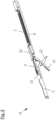
- the movement mechanisms are in modules M, see Figures 1 to 11 , the seal is provided.
- the seal shown has two Modules M. Especially for longer seals, more than two modules can be provided.
- each of the modules has a module carrier 8, one of the push rods 5 and one of the springs 7.
- the module carrier 8 is fastened in the housing 1. In the fastened state, it cannot be moved relative to the housing 1.
- the movement mechanism 4 of each module M is a scissor mechanism with a first scissor element 41 and a second scissor element 42.
- the two scissor elements are connected to each other via a pivot bearing L.
- a first end of the first scissor element 41 is rotatably connected to the module carrier 8 of each module M.
- the first scissor element has two outward-facing pivot pins that engage in recesses in the module carrier 8.
- a second end of the first scissor element 41 is rotatably and slidably mounted in or on the holding rail 2 of the sealing strip 2, 3. This second end has a slot into which the rod 5 of the module is inserted in the release position.
- a first end of the second scissor element 42 is rotatably connected to the push rod 5 of the module M.
- a second end of the second scissor element 42 is rotatably connected to the holding rail 2 of the sealing strip 2, 3.
- a pin is provided on the second end, which engages in a channel of the holding rail 2.
- the second scissor element 42 has a window through which the push rod 5 is guided.
- the scissor mechanism 41, 42 itself is in the European patent application 19 166 220.4 described.
- the module carrier 8 has a guide element 81 which forms a guide channel in which the push rod 5 is guided so that it can be moved linearly relative to the module carrier 8 and the housing 1.
- An axis 421 of the second scissor element 42 is accommodated in a recess 432 with a semicircular cross-section of a bearing element 43 for the rotatable connection between the second scissor element and the push rod 5.
- the bearing element 43 is inserted into a gap between two guide elements 422 of the second scissor element. These two guide elements 422 not only serve to position the bearing element 43.
- the push rod 5 is also guided between these guide elements 422.
- the guide elements 422 with circular arc-shaped contours roll on an inner side of the housing of the seal when the movement mechanism 4 is actuated.
- the bearing element 43 has a protruding nose 433 through which a channel 431 is formed. A section of an O-ring 9 is suspended behind this nose 433.
- the suspended section of the O-ring 9 lies in the channel 431.
- the O-ring 9 is also suspended on a nose 52 of the push rod 5.
- the O-ring 9 is stretched between the noses 433, 52 and thus pulls the bearing element 43 against the rod.
- the axis 421 of the second scissor element arranged in the recess 432 of the bearing element 43 is thereby also pressed into a bulge in the push rod 5, which is formed by a further nose 51 of the rod is formed.
- the axis 421 is thereby mounted between the bearing element 43 and the push rod 5 as long as the force of the O-ring 9 is sufficiently large to pull the bearing element 43 against the push rod 5.
- the O-ring 9 is the overload spring which prevents damage to the seal, in particular to the movement mechanism, if the sealing strip 2, 3 cannot perform any or sufficient stroke when the seal is actuated by introducing a force into the trigger and into the push rod n5, 5a. If the bearing for the axis 421 were provided in a recess in the push rod 5, in a case in which the sealing strip 2, 3 cannot be moved further in the direction of the sealing position because it has encountered resistance, the push rod 5 could also not be moved despite the continued introduction of force into the trigger 6. The continued introduction of force can then lead to damage to the seal.
- the bearing element 43 can lift off the push rod 5.
- the axis 421 of the second scissor element then also detaches from the push rod 5 and is pressed further into the recess 432 by the force of the resistance that opposes the sealing strip.
- the push rod 5 can be moved further by the force introduced via the trigger 6 without any force being transmitted to the movement mechanism.
- the push rods 5 of the modules M are coupled to one another via the push rod 5a.
- the coupling of the push rods 5 of the modules M with the push rod 5a takes place in guide elements 10 which are fastened in the housing. These have a guide channel in which the ends of the push rods 5 or the push rod 5a are guided.
- the push rods 5, 5a butt against each other in the guide channel.
- the push rods 5, 5a are not attached to each other. Therefore, only a compressive force and not a tensile force can be transmitted between the push rods 5, 5a.
- the guide elements 10 are so long that the joint between the push rods 5, 5a remains in the guide channel even if the push rods 5, 5a are moved when the seal is actuated.
- the push rod of the module 5, which is arranged next to the trigger 6, is connected to the trigger on the trigger side.
- This connection is also provided in a guide element 10.
- the connection is a snap connection that can be subjected to pressure and, within certain limits, to tensile stress. Because the connection can also be subjected to tensile stress within certain limits, it is possible to transfer a compressive force exerted on the trigger 6 to actuate the seal to the push rods 5, 5a and the movement mechanisms 4. At the same time, the trigger 6 is held in the housing 1 by the snap connection and cannot fall off the rest of the seal. However, if a tensile force exerted on the trigger 6 exceeds a certain limit, the snap connection is released and the trigger 6 can be removed from the housing 1. This may be necessary if the length of the trigger 6 is to be adjusted.
- the first component 61 has a stop surface at a first end located outside the housing 1, with which the trigger 6 can strike against a door frame when the door is closed. This transfers a pressure force to the trigger 6, which causes the sealing strip 2, 3 to move from the release position to the sealing position.
- the first component 61 of the trigger 6 has a threaded hole.
- the second component 62 of the trigger 6 has a threaded pin at one end facing the first component 61.
- This threaded pin has a T-shaped cross-sectional profile. Only the outer sides of the pin lie on a circular line and have threads that interact with the thread of the threaded hole in the first component 61.
- the length of the trigger 6 can be determined by selecting the screwing depth of the threaded pin into the threaded hole.
- the push rod 5 of each module M has a recess in which the spring 7 is accommodated.
- This spring 7 has a first end which is connected to the push rod 5 of the module M.
- a second end of the spring 7 of the module M is connected to the module carrier 8 of the module M.
- the attachment point of the spring 7 on the module carrier 8 is in front of the attachment point of the spring 7 on the push rod 5 in the direction of movement of the push rod 5 when actuated by pressing the trigger 6.
- the spring 7 is a tension spring.
- the sealing strip is moved from the release position to the sealing position by actuating the seal by pressing the trigger 6, whereby the sealing strip 2, 3 is moved parallel to the housing 1 in the direction out of the housing 1.
- the springs 7 can relax and contract.
- the movement mechanisms 4 are then operated in the opposite direction and the Sealing strip 2, 3 is raised and held in the raised position by the springs 7.
Landscapes
- Engineering & Computer Science (AREA)
- Civil Engineering (AREA)
- Structural Engineering (AREA)
- Specific Sealing Or Ventilating Devices For Doors And Windows (AREA)
Description
- Die vorliegende Erfindung betrifft eine automatische Dichtung für eine Tür
- mit einem Haltemittel,
- mit einer Dichtungsleiste, die ein Dichtungsprofil aufweist,
- mit einem Auslöser zum Einleiten einer Kraft in die Dichtung zum Bewegen der Dichtungsleiste,
- mit einer Schubstange und mit wenigstens einem Mechanismus zur Übertragung einer Bewegung des Auslösers auf die Dichtungsleiste, die mittels des Bewegungsmechanismus von einer Dichtstellung in eine Freigabestellung und umgekehrt bewegbar ist,
- mit wenigstens einer Überlastfeder,
- wobei die Schubstange mit dem Auslöser gekoppelt ist, um die Bewegung des Auslösers auf die Schubstange zu übertragen und
- wobei die Schubstange über die Überlastfeder mit dem Bewegungsmechanismus gekoppelt ist.
- Eine solche Dichtung ist in der Anmeldung
EP 19 166 220.4 EP 3 699 384 A1 beschrieben. - Als Rückstellfeder und auch als Überlastfedern sind in bei den in der Anmeldung
EP 19 166 220.4 EP 3 699 384 A1 offenbarten Dichtungen Schraubenfedern vorgesehen. Schraubenfedern haben einen im Wesentlichen kreisförmigen Querschnitt. Damit sie in der Dichtung angeordnet werden können, muss entsprechend dem Durchmesser Platz vorgesehen sein. Das schränkt den Konstrukteur der sehr schmalen Dichtungen aus der AnmeldungEP 19 166 220.4 EP 3 699 384 A1 bei der Konstruktion ein. - Eine Dichtung mit den eingangs genannten Merkmalen ist auch in der Anmeldung
EP 20 154 981.3 - Der Erfindung lag die Aufgabe zugrunde, ohne auf Schraubenfedern zurückzugreifen eine Alternative zu Federn mit einem Wellen-, Dreiecks-, Sägezahnprofil oder einem ähnlich gebogenen Profil vorzuschlagen, für die auf standardisierte Artikel zurückgegriffen werden kann.
- Diese Aufgabe wird erfindungsgemäß dadurch gelöst, dass die Überlastfeder eine Feder aus einem Elastomer ist. Zusätzlich kann auch die Rückstellfeder eine Feder aus einem Elastomer sein. Die Überlastfeder aber auch die Rückstellfeder kann ein Ring, insbesondere ein O-Ring sein, der in großer Stückzahl preiswert beschafft werden kann.
- Die Stange kann wenigstens einen Vorsprung, eine Nase, einen Haken oder ein ähnliches Element aufweisen, an dem die Rückstellfeder und/oder die Überlastfeder eingehängt sein kann.
- Die Rückstellfeder kann unmittelbar oder mittelbar an dem Haltemittel eingehängt sein.
- Die Überlastfeder kann unmittelbar oder mittelbar an einem Element des Bewegungsmechanismus eingehängt sein. Durch die Überlastfeder wird das Element des Bewegungsmechanismus gegenüber der Stange fixiert, so lange die Dichtungsleiste bewegt werden kann, ohne dass sie gegen ein Hindernis stößt.
- Der Bewegungsmechanismus kann ein Scherenmechanismus sein, der ein erstes, an dem Haltemittel drehbar gelagertes Scherenelement und ein zweites, drehbar an dem ersten Scherenelement gelagertes und zumindest drehbar an der Dichtungsleiste gelagertes Scherenelement aufweist.
- Der Bewegungsmechanismus kann ein Lagerelement aufweisen, gegenüber dem die Stange linear verschiebbar ist und an dem das zweite Scherenelement ebenfalls drehbar gelagert ist und an dem die Überlastfeder eingehängt ist.
- Das zweite Scherenelement kann einen ersten Spalt aufweisen, in den das Lagerelement eintauchen kann, insbesondere wenn kein Überlastfall vorliegt. Durch das Eintauchen des Lagerelementes in den ersten Spalt des Lagerelementes ist es möglich das Lagerelement und das zweite Scherenelement zumindest dann zu einander zu positionieren, wenn kein Überlastfall vorliegt.
- Das Lagerelement kann wenigstens einen Vorsprung, eine Nase, einen Haken oder ein ähnliches Element aufweisen, an dem die die Überlastfeder eingehängt ist. Das zweite Scherenelement kann einen zweiten Spalt oder ein Fenster aufweisen, durch den bzw. das die Stange geführt ist.
- Ferner ist es möglich, dass das erste Scherenelement einen Spalt aufweist, in das die Stange in der Freigabestellung der Dichtungsleiste eintaucht. Dann sind in der Freigabestellung die Stange und das erste Scherenelement zueinander positioniert.
- Der Bewegungsmechanismus könnte auch eine Blattfeder oder einen elastischen Stab umfassen, der die bzw. der mit einem ersten Ende mit dem Haltemittel verbunden ist und deren bzw. dessen zweites Ende über die Überlastfeder mittelbar oder mit dem Stab verbunden ist. Durch eine Bewegung des Stabes gegenüber dem Haltemittel kann die Blattfeder oder der elastische Stab gebogen werden. Dadurch kann der Bereich zwischen den beiden Enden der Blattfeder bzw. des elastischen Stabs ausgelenkt werden. An diesem ausgelenkten Bereich kann die Dichtungsleiste befestigt sein, die durch das Auslenken aus der Freigabestellung in die Dichtstellung verschoben werden kann. Die Verbindung zwischen dem zweiten Ende der Blattfeder oder des elastischen Stabs mit dem Stab erfolgt in der Weise, dass das zweite Ende an den Stab gezogen ist, so lange die Dichtungsleiste beim Bewegen der Dichtungsleiste aus der Freigabestellung in die Dichtstellung auf einen Widerstand stößt.
- Das Haltemittel kann ein Gehäuse sein. Es ist aber auch möglich, dass das Haltemittel ein Modulträger einer modular aufgebauten Dichtung ist, bei der jedes Modul einen Bewegungsmechanismus und eine Stange aufweist. Jedes Modul kann eine Rückstellfeder und/oder eine Überlastfeder aufweisen.
- Weitere Merkmale und Vorteile der vorliegenden Erfindung werden deutlich anhand der nachfolgenden Beschreibung eines Ausführungsbeispiels unter Bezugnahme auf die beiliegenden Abbildungen. Darin zeigen:
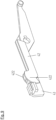
- Fig. 1
- ein Modul der erfindungsgemäßen Dichtung mit einem Bewegungsmechanismus in Freigabestellung,
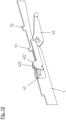
- Fig. 2
- einen vergrößerten Ausschnitt aus
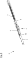
Fig. 1 , - Fig. 3
- das Modul mit dem Bewegungsmechanismus in Dichtstellung,
- Fig. 4
- einen vergrößerten Ausschnitt aus
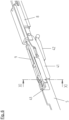
Fig. 3 , - Fig. 5
- das Modul im Überlastfall,
- Fig. 6
- einen vergrößerten Ausschnitt aus
Fig. 5 , - Fig. 7
- eine Ansicht entsprechend
Fig. 6 jedoch mit der Darstellung des Moduls im Überlastfall in einem Längsschnitt, - Fig. 8
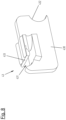
- eine Ansicht eines Lagerelements des Bewegungsmechanismus,
- Fig. 9
- eine Ansicht des Lagerelementes und eines zweiten Scherenelementes des Bewegungsmechanismus
- Fig. 10
- eine Ansicht des Lagerelementes und des zweiten Scherenelementes und der Stange,
- Fig. 11
- einen Querschnitt durch das Modul in der Position der Linie XI-XI in
Fig. 6 , - Fig. 12
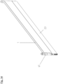
- eine Seitenansicht einer erfindungsgemäßen Dichtung mit einer Dichtungsleiste in einer Freigabestellung,
- Fig. 13
- eine Seitenansicht der Dichtung aus
Fig. 1 mit der Dichtungsleiste in der Dichtstellung und - Fig. 14
- eine perspektivische Darstellung der Dichtung in der Dichtstellung
- Die in den
Figuren 12 bis 14 dargestellte erfindungsgemäße Dichtung ist eine Dichtung, die als automatische Bodendichtung in Flügeltüren eingesetzt werden kann. Die Dichtung kann auch an anderen Türen, zum Beispiel an Schiebetüren, oder an anderen Stellen einer Tür, zum Beispiel an einem oberen Ende der Tür eingesetzt werden. Dazu sind ggf. Änderungen notwendig, die aber die Eigenschaften, die die Dichtung von bekannten Dichtungen unterscheidet, nicht betreffen. - Die Dichtung hat ein Gehäuse 1 und eine Dichtungsleiste 2, 3. Die Dichtungsleiste 2, 3 hat eine Halteschiene 2 und ein Dichtungsprofil 3 aus einem Elastomer. Die Dichtungsleiste 2, 3 ist über einen Bewegungsmechanismus 4 mit dem Gehäuse 1 verbunden. Der Bewegungsmechanismus ist über Schubstangen 5, 5a mit einem Auslöser 6 verbunden, der das Gehäuse 1 an einer Stirnseite überragt. Durch Druck auf eine Anschlagfläche 61 den Auslöser 6 kann die Dichtungsleiste 2, 3 aus einer Freigabestellung in eine Dichtstellung überführt werden. Wird der Auslöser 6 entlastet, wird die Dichtungsleiste von Federn 7 in die Freigabestellung bewegt und in dieser Freigabestellung gehalten.
- Die Bewegungsmechanismen sind in Modulen M, siehe
Figuren 1 bis 11 , der Dichtung vorgesehen. Die dargestellte Dichtung weist zwei Module M auf. Insbesondere bei längeren Dichtungen können auch mehr als zwei Module vorgesehen sein. - Neben dem Bewegungsmechanismus 4 weist jedes der Module einen Modulträger 8, eine der Schubstangen 5 und eine der Federn 7 auf.
- Der Modulträger 8 ist in dem Gehäuse 1 befestigt. Er kann in dem befestigten Zustand gegenüber dem Gehäuse 1 nicht bewegt werden.
- Der Bewegungsmechanismus 4 jedes Moduls M ist ein Scherenmechanismus mit einem ersten Scherenelement 41 und einem zweiten Scherenelement 42. Die beiden Scherelemente sind über ein Drehlager L miteinander verbunden.
- Ein erstes Ende des ersten Scherenelements 41 ist mit dem Modulträger 8 jedes Moduls M drehbar verbunden. Das erste Scherenelement weist dazu zwei nach außen gerichtete Drehzapfen auf, die in Ausnehmungen des Modulträgers 8 eingreifen. Ein zweites Ende des ersten Scherenelementes 41 ist drehbar und verschiebbar in oder an der Halteschiene 2 der Dichtungsleiste 2, 3 gelagert. Dieses zweite Ende weist einen Schlitz auf, in den in der Freigabestellung die Stange 5 des Moduls eintaucht.
- Ein erstes Ende des zweiten Scherenelementes 42 ist mit der Schubstange 5 des Moduls M drehbar verbunden. Ein zweites Ende des zweiten Scherenelementes 42 ist mit der Halteschiene 2 der Dichtungsleiste 2, 3 drehbar verbunden. Dazu ist an dem zweiten Ende ein Zapfen vorgesehen, der in einen Kanal der Halteschiene 2 eingreift. Das zweite Scherenelement 42 weist ein Fenster auf, durch das die Schubstange 5 geführt ist.
- Der Scherenmechanismus 41, 42 an sich ist in der
europäischen Patentanmeldung 19 166 220.4 - Der Modulträger 8 weist ein Führungselement 81 auf, das einen Führungskanal bildet, in dem die Schubstange 5 geführt ist, so dass diese linear gegenüber dem Modulträger 8 und dem Gehäuse 1 verschoben werden kann. Bei einer Verschiebung der Schubstange 5 in der Art, dass das erste Ende des zweiten Scherenelementes 42 auf das erste Ende des ersten Scherenelementes zubewegt wird, werden die zweiten Enden der Scherenelemente 41, 42 nach unten bewegt, wodurch die Dichtungsleiste 2, 3 nach unten abgesenkt wird.
- Eine Achse 421 des zweiten Scherenelementes 42 ist für die drehbare Verbindung zwischen dem zweiten Scherenelement und der Schubstange 5 in einer Ausnehmung 432 mit halbkreisförmigem Querschnitt eines Lagerelements 43 aufgenommen. Das Lagerelement 43 taucht dazu in einen Spalt zwischen zwei Führungselemente 422 des zweiten Scherenelements ein. Diese beiden Führungselemente 422 dienen nicht nur dazu, das Lagerelement 43 zu positionieren. Auch die Schubstange 5 wird zwischen diesen Führungselementen 422 geführt. Ferner rollen die Führungselemente 422 mit kreisbogenförmigen Konturen bei einer Betätigung des Bewegungsmechanismus 4 auf einer Innenseite des Gehäuses der Dichtung ab. Das Lagerelement 43 weist eine vorspringende Nase 433 auf durch die ein Kanal 431 gebildet ist. Hinter dieser Nase 433 ist ein Abschnitt eines O-Ring 9 eingehängt. Der einhängte Abschnitt des O-Rings 9 liegt in dem Kanal 431. Der O-Ring 9 ist ferner an einer Nase 52 der Schubstange 5 eingehängt. Der O-Ring 9 ist zwischen den Nasen 433, 52 gespannt und zieht so das Lagerelement 43 gegen die Stange. Die in der Ausnehmung 432 des Lagerelementes 43 angeordnete Achse 421 des zweiten Scherenelementes wird dadurch auch in eine Ausbuchtung die Schubstange 5 gedrückt, die u.a. durch eine weitere Nase 51 der Stange gebildet wird. Die Achse 421 ist dadurch zwischen dem Lagerelement 43 und der Schubstange 5 gelagert, so lange die Kraft des O-Rings 9 hinreichend groß ist, das Lagerelement 43 gegen die Schubstange 5 zu ziehen.
- Der O-Ring 9 ist die Überlastfeder, die eine Beschädigung der Dichtung, insbesondere des Bewegungsmechanismus verhindert, falls bei einer Betätigung der Dichtung durch Einleitung einer Kraft in den Auslöser und in die Schubstange n5, 5a die Dichtungsleiste 2, 3 keinen oder keinen ausreichenden Hub ausführen kann. Wäre das Lager für die Achse 421 in einer Ausnehmung der Schubstange 5 vorgesehen, könnte in einem Fall, in dem die Dichtungsleiste 2, 3 nicht weiter in Richtung der Dichtstellung bewegt werden kann, da sich auf einen Widerstand gestoßen ist, die Schubstange 5 trotz anhaltender Krafteinleitung in den Auslöser 6 ebenfalls nicht bewegt werden. Die anhaltenden Krafteinleitung kann dann zu einer Beschädigung der Dichtung führen. Bei einer erfindungsgemäßen Dichtung hingegen kann, sobald die über den Auslöser 6 in die Dichtung eingeleitete Kraft größer wird als die von der Überlastfeder 9 aufgebrachte Feder, das Lagerelement 43 von der Schubstange 5 abheben. Die Achse 421 des zweiten Scherenelementes löst sich dann ebenfalls von der Schubstange 5 und wird von der Kraft des Widerstands, der sich der Dichtungsleiste entgegenstellt weiter in die Ausnehmung 432 gedrückt. Die Schubstange 5 kann durch die über den Auslöser 6 eingeleitete Kraft weiter bewegt werden, ohne dass ein Kraft in den Bewegungsmechanismus übertragen wird.
- Die Schubstangen 5 der Module M sind über die Schubstange 5a miteinander gekoppelt. Die Kopplung der Schubstangen 5 der Module M mit der Schubstange 5a erfolgt dabei in Führungselementen 10, die in dem Gehäuse befestigt sind. Diese weisen einen Führungskanal auf, in dem die Enden der Schubstangen 5 bzw. der Schubstange 5a geführt sind. Die Schubstangen 5, 5a stoßen in dem Führungskanal stumpf aneinander. Die Schubstangen 5, 5a sind nicht aneinander befestigt. Daher kann zwischen den Schubstangen 5, 5a nur eine Druckkraft aber keine Zugkraft übertragen werden. Die Führungselemente 10 sind so lang, dass die Stoßstelle zwischen den Schubstangen 5, 5a auch bei einem Verschieben der Schubstangen 5, 5a bei einer Betätigung der Dichtung in dem Führungskanal bleibt.
- Die Schubstange des Moduls 5, das benachbart zum Auslöser 6 angeordnet ist, ist auslöserseitig mit dem Auslöser verbunden. Diese Verbindung ist ebenfalls in einem Führungselement 10 vorgesehen. Die Verbindung ist eine Schnappverbindung, die auf Druck und in gewissen Grenzen auch auf Zug belastet werden kann. Dadurch, dass die Verbindung in gewissen Grenzen auch auf Zug belastet werden kann, ist es möglich, eine auf den Auslöser 6 zur Betätigung der Dichtung ausgeübte Druckkraft auf die Schubstangen 5, 5a und die Bewegungsmechanismen 4 zu übertragen. Zugleich wird der Auslöser 6 durch die Schnappverbindung in dem Gehäuse 1 gehalten und kann von der übrigen Dichtung nicht abfallen. Übersteigt eine auf den Auslöser 6 ausgeübte Zugkraft allerdings die gewisse Grenze, wird die Schnappverbindung gelöst und der Auslöser 6 kann aus dem Gehäuse 1 entnommen werden. Das kann notwendig sein, wenn die Länge des Auslösers 6 eingestellt werden soll.
- Damit der Auslöser 6 eingestellt werden kann, ist er aus zwei Bauteilen 61, 62 zusammengesetzt. Das erste Bauteil 61 hat an einem ersten, außerhalb des Gehäuses 1 liegenden Ende eine Anschlagfläche, mit der der Auslöser 6 gegen einen Türrahmen schlagen kann, wenn die Tür geschlossen wird. Dadurch wird eine Druckkraft auf den Auslöser 6 übertragen, die zur Verschiebung der Dichtungsleiste 2, 3 aus der Freigabestellung in die Dichtstellung führt. An einem zweiten, innerhalb des Gehäuses 1 liegenden Ende hat das erste Bauteil 61 des Auslösers 6 eine Gewindebohrung.
- Das zweite Bauteil 62 des Auslösers 6 hat an einem dem ersten Bauteil 61 zugewandten Ende einen Gewindezapfen. Dieser Gewindezapfen hat ein T-förmiges Querschnittsprofil. Nur die Außenseiten des Zapfens liegen auf einer Kreislinie und weisen Gewindegänge auf, die mit dem Gewinde der Gewindebohrung im ersten Bauteil 61 zusammenwirken. Durch die Wahl der Eischraubtiefe des Gewindezapfens in die Gewindebohrung kann die Länge des Auslösers 6 bestimmt werden.
- Die Schubstange 5 jeden Moduls M hat eine Ausnehmung, in der die Feder 7 aufgenommen ist. Diese Feder 7 hat ein erstes Ende, das mit der Schubstange 5 des Moduls M verbunden ist. Ein zweites Ende der Feder 7 des Moduls M ist mit dem Modulträger 8 des Moduls M verbunden. Der Befestigungspunkt der Feder 7 an dem Modulträger 8 liegt dabei in der Bewegungsrichtung der Schubstange 5 bei einer Betätigung durch Druck auf den Auslöser 6 vor dem Befestigungspunkt der Feder 7 an der Schubstange 5. Dadurch wird die Feder 7 bei einer Betätigung der Dichtung durch Druck auf den Auslöser gelängt und dadurch gespannt. Bei der Feder 7 handelt es sich um eine Zugfeder. Gleichzeitig zum Spannen der Federn 7 wird die Dichtungsleiste durch die Betätigung der Dichtung durch Druck auf den Auslöser 6 aus der Freigabestellung in die Dichtstellung bewegt, wobei die Dichtungsleiste 2, 3 parallel zum Gehäuse 1 in Richtung aus dem Gehäuse 1 heraus verschoben wird.
- Wird dann der Druck von dem Auslöser 6 genommen, können sich die Federn 7 entspannen und zusammenziehen. Dabei werden die Bewegungsmechanismen 4 in umgekehrter Richtung betätigt und die Dichtungsleiste 2, 3 wird angehoben und von den Federn 7 in der angehobenen Stellung gehalten.
Claims (11)
- Automatische Dichtung für eine Tür- mit einem Haltemittel (8),- mit einer Dichtungsleiste (2, 3), die ein Dichtungsprofil (3) aufweist,- mit einem Auslöser (6) zum Einleiten einer Kraft in die Dichtung zum Bewegen der Dichtungsleiste (2, 3),- mit einer Schubstange (5) und mit wenigstens einem Mechanismus (4) zur Übertragung einer Bewegung des Auslösers (6) auf die Dichtungsleiste (2, 3), die mittels des Bewegungsmechanismus (4) von einer Dichtstellung in eine Freigabestellung und umgekehrt bewegbar ist,- mit wenigstens einer Überlastfeder (9),- wobei die Schubstange (5) mit dem Auslöser (6) gekoppelt ist, um die Bewegung des Auslösers (6) auf die Schubstange (5) zu übertragen,- wobei die Schubstange (5) über die Überlastfeder (9), mit dem Bewegungsmechanismus (4) gekoppelt ist,dadurch gekennzeichnet, dass
die Überlastfeder (9) eine Feder aus einem Elastomer ist. - Dichtung nach Anspruch 1, dadurch gekennzeichnet, dass die Überlastfeder (9) ein Ring, insbesondere ein O-Ring ist.
- Dichtung nach Anspruch 1 oder 2, dadurch gekennzeichnet, dass die Schubstange (5) wenigstens einen Vorsprung, eine Nase (52), einen Haken oder ein ähnliches Element aufweist, an dem die Überlastfeder (9) eingehängt ist.
- Dichtung nach einem der Ansprüche 1 bis 3, dadurch gekennzeichnet, dass die Überlastfeder (9) unmittelbar oder mittelbar an einem Element (43) des Bewegungsmechanismus (4) eingehängt ist.
- Dichtung nach einem der Ansprüche 1 bis 4, dadurch gekennzeichnet, dass der Bewegungsmechanismus (4) ein Scherenmechanismus (41, 42) ist, der ein erstes, an dem Haltemittel (8) drehbar gelagertes Scherenelement (41) und ein zweites, drehbar an dem ersten Scherenelement (41) gelagertes und zumindest drehbar an der Dichtungsleiste (2, 3) gelagertes Scherenelement (42) aufweist.
- Dichtung nach den Ansprüchen 4 und 5, dadurch gekennzeichnet, dass der Bewegungsmechanismus (4) ein Lagerelement (43) aufweist, gegenüber dem die Schubstange (5) linear verschiebbar ist und an dem das zweite Scherenelement (42) ebenfalls drehbar gelagert ist und an dem die Überlastfeder (9) eingehängt ist.
- Dichtung nach Anspruch 6, dadurch gekennzeichnet, dass das Lagerelement (43) in einen ersten Spalt des zweiten Scherenelements (42) eintaucht.
- Dichtung nach Anspruch 6 oder 7, dadurch gekennzeichnet, dass das Lagerelement (43) wenigstens einen Vorsprung, eine Nase (433), einen Haken oder ein ähnliches Element aufweist, an dem die die Überlastfeder (9) eingehängt ist.
- Dichtung nach einem der Ansprüche 5 bis 8, dadurch gekennzeichnet, dass das zweite Scherenelement (42) einen zweiten Spalt oder ein Fenster aufweist, durch den bzw. das die Schubstange (5) geführt ist.
- Dichtung nach einem der Ansprüche 6 bis 9, dadurch gekennzeichnet, dass das erste Scherenelement (41) einen Spalt aufweist, in das die Schubstange (5) in der Freigabestellung der Dichtungsleiste (2, 3) eintaucht.
- Dichtung nach einem der Ansprüche 5 bis 10, dadurch gekennzeichnet, dass die Dichtung eine Rückstellfeder aufweist, wobei die Schubstange (5) über die Rückstellfeder zumindest mittelbar mit dem Haltemittel verbunden ist,
dadurch gekennzeichnet, dass
die Rückstellfeder eine Feder aus einem Elastomer ist.
Priority Applications (1)
| Application Number | Priority Date | Filing Date | Title |
|---|---|---|---|
| EP20209592.3A EP4001577B1 (de) | 2020-11-24 | 2020-11-24 | Automatische dichtung mit einer überlastfeder aus elastomer |
Applications Claiming Priority (1)
| Application Number | Priority Date | Filing Date | Title |
|---|---|---|---|
| EP20209592.3A EP4001577B1 (de) | 2020-11-24 | 2020-11-24 | Automatische dichtung mit einer überlastfeder aus elastomer |
Publications (2)
| Publication Number | Publication Date |
|---|---|
| EP4001577A1 EP4001577A1 (de) | 2022-05-25 |
| EP4001577B1 true EP4001577B1 (de) | 2024-11-06 |
Family
ID=73597822
Family Applications (1)
| Application Number | Title | Priority Date | Filing Date |
|---|---|---|---|
| EP20209592.3A Active EP4001577B1 (de) | 2020-11-24 | 2020-11-24 | Automatische dichtung mit einer überlastfeder aus elastomer |
Country Status (1)
| Country | Link |
|---|---|
| EP (1) | EP4001577B1 (de) |
Family Cites Families (4)
| Publication number | Priority date | Publication date | Assignee | Title |
|---|---|---|---|---|
| US16341A (en) * | 1857-01-06 | Weather-strip for doors | ||
| US384003A (en) * | 1888-06-05 | Joseph thompson and john o | ||
| FR802747A (fr) * | 1935-03-11 | 1936-09-14 | Dispositif empêchant les courants d'air de passer au-dessous des portes, fenêtres, etc. | |
| DK3699384T3 (da) * | 2019-02-20 | 2022-10-24 | Athmer Ohg | Tætning med en sænkbar tætningsliste, der kan sænkes ved hjælp af en sænkningsmekanisme, der kan betjenes af en udløser |
-
2020
- 2020-11-24 EP EP20209592.3A patent/EP4001577B1/de active Active
Also Published As
| Publication number | Publication date |
|---|---|
| EP4001577A1 (de) | 2022-05-25 |
Similar Documents
| Publication | Publication Date | Title |
|---|---|---|
| EP2085559B1 (de) | Absenkbare Dichtungsvorrichtung | |
| EP2474698B1 (de) | Dichtungsvorrichtung mit einem Dichtungsprofil und einem Mechanismus zum Verschieben des Dichtungsprofils bei Betätigung des Mechanismus | |
| EP3284898B1 (de) | Dichtung mit einer über zwei scherenmechanismen absenkbaren dichtleiste | |
| DE10347528B3 (de) | Türöffner | |
| DE102005042510A1 (de) | Außenliegende mechanische Verriegelung für einen Linearaktuator | |
| EP2634350B1 (de) | Bewegliche Dichtung, insbesondere Schiebetürdichtung | |
| DE102004011880A1 (de) | Schließblech für Fenster oder Fenstertüren | |
| DE102016202377A1 (de) | Beschlaganordnung zur Anbindung eines schieb- und kippbaren Flügels | |
| EP4012141B1 (de) | Montagekonsole für einen türbetätiger | |
| EP3868994B1 (de) | Dichtung mit modulen, die einen absenkmechanismus aufweisen | |
| EP2725173A2 (de) | Schnäpperschloss, insbesondere als Zusatzverriegelung einer Tür, eines Tors oder eines Fensters | |
| EP4001577B1 (de) | Automatische dichtung mit einer überlastfeder aus elastomer | |
| EP1420136B1 (de) | Treibstangenbeschlag für einen unterschlagenden Flügel eines zweiflügeligen, setzholzlosen Fensters oder einer Tür, und Verfahren zur automatischen oder teilautomatischen Montage eines Treibstangenbeschlags | |
| DE3520861A1 (de) | Rueckdruecksperre an treibstangenbeschlaegen, insbesondere schluesselbetaetigbaren treibstangenschloessern | |
| DE19646982A1 (de) | Beschlag für ein Fenster | |
| DE2257744A1 (de) | Schloss zum verriegeln von tueren oder fenstern | |
| EP3725992B1 (de) | Antrieb | |
| EP2672046A2 (de) | Führungsschienenanordnung | |
| DE20109265U1 (de) | Verriegelungsvorrichtung | |
| DE202017101426U1 (de) | Werkzeug zum Entfernen und Anbringen von Rohrschellen | |
| DE102020109074A1 (de) | Vorrichtung zur unterstützung des schliessens und öffnens eines hebe-schiebeelements | |
| EP3599335B1 (de) | Absenkbare dichtung, insbesondere für schiebetore | |
| EP4386170B1 (de) | Automatische dichtung für schiebetüren oder -tore | |
| EP3287577B1 (de) | Schliessvorrichtung für eine tür, ein fenster oder dergleichen | |
| EP4276267B1 (de) | Dichtung, insbesondere für schiebetüren oder schiebtore |
Legal Events
| Date | Code | Title | Description |
|---|---|---|---|
| PUAI | Public reference made under article 153(3) epc to a published international application that has entered the european phase |
Free format text: ORIGINAL CODE: 0009012 |
|
| STAA | Information on the status of an ep patent application or granted ep patent |
Free format text: STATUS: REQUEST FOR EXAMINATION WAS MADE |
|
| 17P | Request for examination filed |
Effective date: 20220414 |
|
| AK | Designated contracting states |
Kind code of ref document: A1 Designated state(s): AL AT BE BG CH CY CZ DE DK EE ES FI FR GB GR HR HU IE IS IT LI LT LU LV MC MK MT NL NO PL PT RO RS SE SI SK SM TR |
|
| STAA | Information on the status of an ep patent application or granted ep patent |
Free format text: STATUS: EXAMINATION IS IN PROGRESS |
|
| 17Q | First examination report despatched |
Effective date: 20230215 |
|
| GRAP | Despatch of communication of intention to grant a patent |
Free format text: ORIGINAL CODE: EPIDOSNIGR1 |
|
| STAA | Information on the status of an ep patent application or granted ep patent |
Free format text: STATUS: GRANT OF PATENT IS INTENDED |
|
| INTG | Intention to grant announced |
Effective date: 20240606 |
|
| P01 | Opt-out of the competence of the unified patent court (upc) registered |
Free format text: CASE NUMBER: APP_48191/2024 Effective date: 20240821 |
|
| GRAS | Grant fee paid |
Free format text: ORIGINAL CODE: EPIDOSNIGR3 |
|
| GRAA | (expected) grant |
Free format text: ORIGINAL CODE: 0009210 |
|
| STAA | Information on the status of an ep patent application or granted ep patent |
Free format text: STATUS: THE PATENT HAS BEEN GRANTED |
|
| AK | Designated contracting states |
Kind code of ref document: B1 Designated state(s): AL AT BE BG CH CY CZ DE DK EE ES FI FR GB GR HR HU IE IS IT LI LT LU LV MC MK MT NL NO PL PT RO RS SE SI SK SM TR |
|
| REG | Reference to a national code |
Ref country code: GB Ref legal event code: FG4D Free format text: NOT ENGLISH |
|
| REG | Reference to a national code |
Ref country code: CH Ref legal event code: EP |
|
| REG | Reference to a national code |
Ref country code: DE Ref legal event code: R096 Ref document number: 502020009678 Country of ref document: DE |
|
| REG | Reference to a national code |
Ref country code: IE Ref legal event code: FG4D Free format text: LANGUAGE OF EP DOCUMENT: GERMAN |
|
| REG | Reference to a national code |
Ref country code: LT Ref legal event code: MG9D |
|
| REG | Reference to a national code |
Ref country code: NL Ref legal event code: MP Effective date: 20241106 |
|
| PG25 | Lapsed in a contracting state [announced via postgrant information from national office to epo] |
Ref country code: PT Free format text: LAPSE BECAUSE OF FAILURE TO SUBMIT A TRANSLATION OF THE DESCRIPTION OR TO PAY THE FEE WITHIN THE PRESCRIBED TIME-LIMIT Effective date: 20250306 Ref country code: HR Free format text: LAPSE BECAUSE OF FAILURE TO SUBMIT A TRANSLATION OF THE DESCRIPTION OR TO PAY THE FEE WITHIN THE PRESCRIBED TIME-LIMIT Effective date: 20241106 Ref country code: IS Free format text: LAPSE BECAUSE OF FAILURE TO SUBMIT A TRANSLATION OF THE DESCRIPTION OR TO PAY THE FEE WITHIN THE PRESCRIBED TIME-LIMIT Effective date: 20250306 |
|
| PG25 | Lapsed in a contracting state [announced via postgrant information from national office to epo] |
Ref country code: FI Free format text: LAPSE BECAUSE OF FAILURE TO SUBMIT A TRANSLATION OF THE DESCRIPTION OR TO PAY THE FEE WITHIN THE PRESCRIBED TIME-LIMIT Effective date: 20241106 Ref country code: NL Free format text: LAPSE BECAUSE OF FAILURE TO SUBMIT A TRANSLATION OF THE DESCRIPTION OR TO PAY THE FEE WITHIN THE PRESCRIBED TIME-LIMIT Effective date: 20241106 |
|
| PG25 | Lapsed in a contracting state [announced via postgrant information from national office to epo] |
Ref country code: BG Free format text: LAPSE BECAUSE OF FAILURE TO SUBMIT A TRANSLATION OF THE DESCRIPTION OR TO PAY THE FEE WITHIN THE PRESCRIBED TIME-LIMIT Effective date: 20241106 |
|
| PG25 | Lapsed in a contracting state [announced via postgrant information from national office to epo] |
Ref country code: ES Free format text: LAPSE BECAUSE OF FAILURE TO SUBMIT A TRANSLATION OF THE DESCRIPTION OR TO PAY THE FEE WITHIN THE PRESCRIBED TIME-LIMIT Effective date: 20241106 |
|
| PG25 | Lapsed in a contracting state [announced via postgrant information from national office to epo] |
Ref country code: NO Free format text: LAPSE BECAUSE OF FAILURE TO SUBMIT A TRANSLATION OF THE DESCRIPTION OR TO PAY THE FEE WITHIN THE PRESCRIBED TIME-LIMIT Effective date: 20250206 |
|
| PG25 | Lapsed in a contracting state [announced via postgrant information from national office to epo] |
Ref country code: GR Free format text: LAPSE BECAUSE OF FAILURE TO SUBMIT A TRANSLATION OF THE DESCRIPTION OR TO PAY THE FEE WITHIN THE PRESCRIBED TIME-LIMIT Effective date: 20250207 Ref country code: LV Free format text: LAPSE BECAUSE OF FAILURE TO SUBMIT A TRANSLATION OF THE DESCRIPTION OR TO PAY THE FEE WITHIN THE PRESCRIBED TIME-LIMIT Effective date: 20241106 |
|
| PG25 | Lapsed in a contracting state [announced via postgrant information from national office to epo] |
Ref country code: PL Free format text: LAPSE BECAUSE OF FAILURE TO SUBMIT A TRANSLATION OF THE DESCRIPTION OR TO PAY THE FEE WITHIN THE PRESCRIBED TIME-LIMIT Effective date: 20241106 |
|
| PG25 | Lapsed in a contracting state [announced via postgrant information from national office to epo] |
Ref country code: RS Free format text: LAPSE BECAUSE OF FAILURE TO SUBMIT A TRANSLATION OF THE DESCRIPTION OR TO PAY THE FEE WITHIN THE PRESCRIBED TIME-LIMIT Effective date: 20250206 |
|
| PG25 | Lapsed in a contracting state [announced via postgrant information from national office to epo] |
Ref country code: SM Free format text: LAPSE BECAUSE OF FAILURE TO SUBMIT A TRANSLATION OF THE DESCRIPTION OR TO PAY THE FEE WITHIN THE PRESCRIBED TIME-LIMIT Effective date: 20241106 |
|
| PG25 | Lapsed in a contracting state [announced via postgrant information from national office to epo] |
Ref country code: DK Free format text: LAPSE BECAUSE OF FAILURE TO SUBMIT A TRANSLATION OF THE DESCRIPTION OR TO PAY THE FEE WITHIN THE PRESCRIBED TIME-LIMIT Effective date: 20241106 |
|
| PG25 | Lapsed in a contracting state [announced via postgrant information from national office to epo] |
Ref country code: LU Free format text: LAPSE BECAUSE OF NON-PAYMENT OF DUE FEES Effective date: 20241124 |
|
| PG25 | Lapsed in a contracting state [announced via postgrant information from national office to epo] |
Ref country code: EE Free format text: LAPSE BECAUSE OF FAILURE TO SUBMIT A TRANSLATION OF THE DESCRIPTION OR TO PAY THE FEE WITHIN THE PRESCRIBED TIME-LIMIT Effective date: 20241106 |
|
| PG25 | Lapsed in a contracting state [announced via postgrant information from national office to epo] |
Ref country code: RO Free format text: LAPSE BECAUSE OF FAILURE TO SUBMIT A TRANSLATION OF THE DESCRIPTION OR TO PAY THE FEE WITHIN THE PRESCRIBED TIME-LIMIT Effective date: 20241106 |
|
| PG25 | Lapsed in a contracting state [announced via postgrant information from national office to epo] |
Ref country code: SK Free format text: LAPSE BECAUSE OF FAILURE TO SUBMIT A TRANSLATION OF THE DESCRIPTION OR TO PAY THE FEE WITHIN THE PRESCRIBED TIME-LIMIT Effective date: 20241106 |
|
| PG25 | Lapsed in a contracting state [announced via postgrant information from national office to epo] |
Ref country code: CZ Free format text: LAPSE BECAUSE OF FAILURE TO SUBMIT A TRANSLATION OF THE DESCRIPTION OR TO PAY THE FEE WITHIN THE PRESCRIBED TIME-LIMIT Effective date: 20241106 |
|
| PG25 | Lapsed in a contracting state [announced via postgrant information from national office to epo] |
Ref country code: IT Free format text: LAPSE BECAUSE OF FAILURE TO SUBMIT A TRANSLATION OF THE DESCRIPTION OR TO PAY THE FEE WITHIN THE PRESCRIBED TIME-LIMIT Effective date: 20241106 |
|
| REG | Reference to a national code |
Ref country code: DE Ref legal event code: R097 Ref document number: 502020009678 Country of ref document: DE |
|
| REG | Reference to a national code |
Ref country code: BE Ref legal event code: MM Effective date: 20241130 |
|
| PG25 | Lapsed in a contracting state [announced via postgrant information from national office to epo] |
Ref country code: SE Free format text: LAPSE BECAUSE OF FAILURE TO SUBMIT A TRANSLATION OF THE DESCRIPTION OR TO PAY THE FEE WITHIN THE PRESCRIBED TIME-LIMIT Effective date: 20241106 |
|
| PLBE | No opposition filed within time limit |
Free format text: ORIGINAL CODE: 0009261 |
|
| STAA | Information on the status of an ep patent application or granted ep patent |
Free format text: STATUS: NO OPPOSITION FILED WITHIN TIME LIMIT |
|
| PG25 | Lapsed in a contracting state [announced via postgrant information from national office to epo] |
Ref country code: MC Free format text: LAPSE BECAUSE OF FAILURE TO SUBMIT A TRANSLATION OF THE DESCRIPTION OR TO PAY THE FEE WITHIN THE PRESCRIBED TIME-LIMIT Effective date: 20241106 |
|
| 26N | No opposition filed |
Effective date: 20250807 |
|
| PG25 | Lapsed in a contracting state [announced via postgrant information from national office to epo] |
Ref country code: BE Free format text: LAPSE BECAUSE OF NON-PAYMENT OF DUE FEES Effective date: 20241130 |
|
| PG25 | Lapsed in a contracting state [announced via postgrant information from national office to epo] |
Ref country code: FR Free format text: LAPSE BECAUSE OF NON-PAYMENT OF DUE FEES Effective date: 20250106 |
|
| PG25 | Lapsed in a contracting state [announced via postgrant information from national office to epo] |
Ref country code: IE Free format text: LAPSE BECAUSE OF NON-PAYMENT OF DUE FEES Effective date: 20241124 |
|
| REG | Reference to a national code |
Ref country code: CH Ref legal event code: U11 Free format text: ST27 STATUS EVENT CODE: U-0-0-U10-U11 (AS PROVIDED BY THE NATIONAL OFFICE) Effective date: 20251201 |
|
| PGFP | Annual fee paid to national office [announced via postgrant information from national office to epo] |
Ref country code: DE Payment date: 20251130 Year of fee payment: 6 |
|
| PGFP | Annual fee paid to national office [announced via postgrant information from national office to epo] |
Ref country code: GB Payment date: 20251121 Year of fee payment: 6 |
|
| PGFP | Annual fee paid to national office [announced via postgrant information from national office to epo] |
Ref country code: AT Payment date: 20251120 Year of fee payment: 6 |
|
| PGFP | Annual fee paid to national office [announced via postgrant information from national office to epo] |
Ref country code: CH Payment date: 20251201 Year of fee payment: 6 |
|
| PG25 | Lapsed in a contracting state [announced via postgrant information from national office to epo] |
Ref country code: HU Free format text: LAPSE BECAUSE OF FAILURE TO SUBMIT A TRANSLATION OF THE DESCRIPTION OR TO PAY THE FEE WITHIN THE PRESCRIBED TIME-LIMIT; INVALID AB INITIO Effective date: 20201124 |
|
| PG25 | Lapsed in a contracting state [announced via postgrant information from national office to epo] |
Ref country code: CY Free format text: LAPSE BECAUSE OF FAILURE TO SUBMIT A TRANSLATION OF THE DESCRIPTION OR TO PAY THE FEE WITHIN THE PRESCRIBED TIME-LIMIT; INVALID AB INITIO Effective date: 20201124 |