EP4004448B1 - Dispositif de réglage et procédé pour déterminer une valeur-seuil hydraulique d'une vanne - Google Patents
Dispositif de réglage et procédé pour déterminer une valeur-seuil hydraulique d'une vanne Download PDFInfo
- Publication number
- EP4004448B1 EP4004448B1 EP20731796.7A EP20731796A EP4004448B1 EP 4004448 B1 EP4004448 B1 EP 4004448B1 EP 20731796 A EP20731796 A EP 20731796A EP 4004448 B1 EP4004448 B1 EP 4004448B1
- Authority
- EP
- European Patent Office
- Prior art keywords
- control valve
- flow control
- flow
- temperature
- opening position
- Prior art date
- Legal status (The legal status is an assumption and is not a legal conclusion. Google has not performed a legal analysis and makes no representation as to the accuracy of the status listed.)
- Active
Links
Images


Classifications
-
- G—PHYSICS
- G05—CONTROLLING; REGULATING
- G05D—SYSTEMS FOR CONTROLLING OR REGULATING NON-ELECTRIC VARIABLES
- G05D27/00—Simultaneous control of variables covered by two or more of main groups G05D1/00 - G05D25/00
- G05D27/02—Simultaneous control of variables covered by two or more of main groups G05D1/00 - G05D25/00 characterised by the use of electric means
-
- F—MECHANICAL ENGINEERING; LIGHTING; HEATING; WEAPONS; BLASTING
- F24—HEATING; RANGES; VENTILATING
- F24D—DOMESTIC- OR SPACE-HEATING SYSTEMS, e.g. CENTRAL HEATING SYSTEMS; DOMESTIC HOT-WATER SUPPLY SYSTEMS; ELEMENTS OR COMPONENTS THEREFOR
- F24D19/00—Details
- F24D19/10—Arrangement or mounting of control or safety devices
- F24D19/1006—Arrangement or mounting of control or safety devices for water heating systems
- F24D19/1009—Arrangement or mounting of control or safety devices for water heating systems for central heating
- F24D19/1015—Arrangement or mounting of control or safety devices for water heating systems for central heating using a valve or valves
- F24D19/1018—Radiator valves
-
- F—MECHANICAL ENGINEERING; LIGHTING; HEATING; WEAPONS; BLASTING
- F24—HEATING; RANGES; VENTILATING
- F24D—DOMESTIC- OR SPACE-HEATING SYSTEMS, e.g. CENTRAL HEATING SYSTEMS; DOMESTIC HOT-WATER SUPPLY SYSTEMS; ELEMENTS OR COMPONENTS THEREFOR
- F24D19/00—Details
- F24D19/10—Arrangement or mounting of control or safety devices
- F24D19/1006—Arrangement or mounting of control or safety devices for water heating systems
- F24D19/1009—Arrangement or mounting of control or safety devices for water heating systems for central heating
- F24D19/1015—Arrangement or mounting of control or safety devices for water heating systems for central heating using a valve or valves
-
- G—PHYSICS
- G05—CONTROLLING; REGULATING
- G05D—SYSTEMS FOR CONTROLLING OR REGULATING NON-ELECTRIC VARIABLES
- G05D23/00—Control of temperature
- G05D23/19—Control of temperature characterised by the use of electric means
- G05D23/1917—Control of temperature characterised by the use of electric means using digital means
-
- G—PHYSICS
- G05—CONTROLLING; REGULATING
- G05D—SYSTEMS FOR CONTROLLING OR REGULATING NON-ELECTRIC VARIABLES
- G05D23/00—Control of temperature
- G05D23/19—Control of temperature characterised by the use of electric means
- G05D23/1927—Control of temperature characterised by the use of electric means using a plurality of sensors
- G05D23/193—Control of temperature characterised by the use of electric means using a plurality of sensors sensing the temperaure in different places in thermal relationship with one or more spaces
- G05D23/1932—Control of temperature characterised by the use of electric means using a plurality of sensors sensing the temperaure in different places in thermal relationship with one or more spaces to control the temperature of a plurality of spaces
- G05D23/1934—Control of temperature characterised by the use of electric means using a plurality of sensors sensing the temperaure in different places in thermal relationship with one or more spaces to control the temperature of a plurality of spaces each space being provided with one sensor acting on one or more control means
-
- Y—GENERAL TAGGING OF NEW TECHNOLOGICAL DEVELOPMENTS; GENERAL TAGGING OF CROSS-SECTIONAL TECHNOLOGIES SPANNING OVER SEVERAL SECTIONS OF THE IPC; TECHNICAL SUBJECTS COVERED BY FORMER USPC CROSS-REFERENCE ART COLLECTIONS [XRACs] AND DIGESTS
- Y02—TECHNOLOGIES OR APPLICATIONS FOR MITIGATION OR ADAPTATION AGAINST CLIMATE CHANGE
- Y02B—CLIMATE CHANGE MITIGATION TECHNOLOGIES RELATED TO BUILDINGS, e.g. HOUSING, HOUSE APPLIANCES OR RELATED END-USER APPLICATIONS
- Y02B30/00—Energy efficient heating, ventilation or air conditioning [HVAC]
- Y02B30/70—Efficient control or regulation technologies, e.g. for control of refrigerant flow, motor or heating
Definitions
- the present application relates to an adjustment device for the temperature-dependent, self-regulating adjustment of a flow control valve in a temperature control system and a corresponding method with a focus on a functionality consisting in determining a hydraulic threshold value of a valve.
- a technical background of the invention lies in the application of heating and air conditioning systems for rooms, such as in particular underfloor heating, surface heating or cooling ceilings, which are installed in a building to provide a selectable room temperature independent of the weather.
- the technology of the aforementioned patent application EN 10 2017 123 560 A1 describes an adjustment device and a method for self-regulating adjustment of a flow in consumer loops with a heat exchanger, which is based on a calculation of an application-optimized temperature spread between the flow temperature and return temperature, i.e. a variable target temperature difference in each consumer loop.
- the adjustment device forms the key component of a temperature control system in which the corresponding method is implemented and which has an associated room thermostat.
- the calculation of a variable spread of the temperature difference serves to independently adjust an optimal operating point in an individual installation environment of the heat exchanger.
- the inclusion of the resulting heating time compensates for the circumstances of the building, such as floor, basement location or external wall ratio as well as the circumstances of the installation, and makes it possible to independently optimize faster room temperature control within an efficient range.
- a majority of corresponding adjustment devices carry out a demand-based distribution of the partial flows in the consumer loops without the need for a central control unit.
- the present invention is concerned with determining a hydraulic minimum opening position of a valve, from which a flow through a consumer loop assigned to the valve takes place.
- the teaching of such a hydraulic threshold value of the valve serves as an initialization or as a calibration of the adjustment device to a valve type used, or to a variable aging state of a seal of the valve, thereby improving an accuracy and a speed of a control for adjusting the valve.
- so-called flow control valves which are used in heating circuits of a heating installation such as underfloor heating or other temperature control systems such as cooling ceilings or the like, have a seal.
- the seal seals off the flow of a liquid heat transfer medium in a closed position of the valve, for example when there is no need for temperature control by the associated consumer loop and its heat exchangers.
- the seal can be arranged on a valve body or a valve plate that is moved via a valve pin.
- the seal is usually made of an elastic material such as rubber. When the valve plate is lifted from a valve seat, the compression of the seal decreases within the resulting valve gap, but the seal does not yet allow flow through the valve gap. Due to the elastic material properties, there is therefore a sealing-effective area along the valve travel. From a hydraulic threshold value, which is to be determined as follows, a minimal flow of the heat transfer medium occurs under a hydraulic pressure applied in front of the valve. In a subsequent hydraulic region along the valve travel, a restricted flow through the valve increases.
- the control operation of a self-regulating adjustment device can be optimized if it can access a value that is assigned to a minimum or as small as possible known opening position of the valve.
- the corresponding threshold value of a valve travel between a hydraulic range and a sealing effective range, in which a flow is almost prevented by a valve seal, is individual.
- a The corresponding transition is expected to be within the lower half of the valve travel, but an absolute value is in principle unknown because it depends both on any compatible valve type and on wear or aging of the seal.
- an arrangement of the valve and a temperature sensor for the flow temperature is preferably provided such that the valve is attached to an inlet distributor pipe, i.e. in the direction of flow upstream of the associated consumer loop, and the temperature sensor for the flow temperature is attached to a line section leading away from the inlet distributor pipe, i.e. in the direction of flow downstream of the valve in an initial area of the consumer loop. No detection of the flow is provided on the valve or an associated line.
- a control system draws conclusions as to whether there is a flow in the consumer loop by comparing the temperatures detected at the beginning and at the end of the consumer loop.
- a possible solution for this regulation could be to teach in the hydraulic threshold value of the valve used during an initialization of the adjustment device, which is carried out by a trained craftsman after installation and before initial commissioning.
- the adjustment device slowly opens the valve, starting from the closed position, while the temperature difference at the beginning and end of the consumer loop is monitored. As soon as the recorded temperatures indicate that the heat transfer medium is flowing, the hydraulic threshold value is set at the corresponding valve setting value. After the initialization process has been completed, the adjustment device is released by the trained craftsman for control operation in the temperature control system.
- the adjustment device for the self-regulating adjustment of a flow control valve is characterized in particular by the fact that it is designed to determine a hydraulic minimum opening position of the flow control valve, at which a minimum flow can be detected, along an adjustment path; and the adjustment device determines a flow through the flow control valve based on a Temperature change of the heat transfer medium in the consumer loop is detected; wherein the determination of the hydraulic minimum opening position comprises iterations of different opening positions along the travel of the flow control valve; each iteration of an opening position of the flow control valve comprises at least one detection of the flow through the flow control valve; and the determination of the hydraulic minimum opening position extends over several external tempering requests to the consumer loop, and missing iterations of the determination that are still outstanding after deactivations of the setting device between the tempering requests are continued when the setting device is activated again.
- the corresponding method according to the invention for self-regulating adjustment of a flow is characterized in particular by the steps: determining a hydraulic minimum opening position of the flow control valve, at which a minimum flow can be detected, along an adjustment path; by detecting a flow through the flow control valve based on a temperature change of the heat transfer medium in the consumer loop; wherein the determination of the hydraulic minimum opening position comprises iterations of different opening positions along the adjustment path of the flow control valve; each iteration of an opening position of the flow control valve comprises at least one detection of the flow through the flow control valve; and the determination of the hydraulic minimum opening position extends over several external temperature control requests to the consumer loop, and missing iterations of the determination that are still outstanding after deactivation of the adjustment device between the temperature control requests are continued when the adjustment device is activated again.
- the invention provides for the first time an independent determination of a hydraulic threshold value of the flow control valve by means of an adjustment device, which is carried out after commissioning of the temperature control system and distributed over time throughout the temperature control operation.
- the invention is based on the idea of automatically carrying out a successive approximation to the threshold value to be determined by the setting device during ongoing operation over several temperature control requirements that occur to open a flow through a consumer loop.
- An external temperature control request within the meaning of this disclosure is made, for example, by a thermostat that outputs a signal, e.g. a binary switch-on signal (ON/OFF) to activate the setting device.
- a thermostat that outputs a signal, e.g. a binary switch-on signal (ON/OFF) to activate the setting device.
- a room thermostat issues a heating request to an underfloor heating system and activates the setting device of a flow control valve on a heating circuit distributor that is assigned to the underfloor heating in the room in question.
- the flow control valve opens the corresponding consumer loop and sets a flow so that the room temperature is brought closer to a target temperature that was set by a user on the room thermostat.
- the setting device can also be activated by another input device such as a switch, through which the user can directly specify a temperature requirement for the setting device.
- the invention has the advantage that the adjustment device can independently learn the hydraulic threshold value of the flow control valve after the temperature control system has been put into operation. This eliminates the need for a craftsman to do the work.
- the hydraulic threshold value is determined over a period of time across several temperature control requirements. There is no need to initialize or calibrate the setting device before the first start-up, for which all other requirements of the temperature control system must be ensured to be ready for operation. Installation of the setting device and start-up of the temperature control system are decoupled in time. It is therefore irrelevant for the determination of the hydraulic threshold value according to the invention whether the setting device for example, it was installed when a building was completed in the summer and was only put into operation for the first time during the heating season in the autumn.
- the invention also has the advantage that the determination of the hydraulic threshold value is suitable for being repeated routinely. This basically enables the adjustment device to adapt itself independently to changes in the hydraulic threshold value, such as due to a replacement of a valve, wear or aging of a seal.
- the first iteration can begin at a hydraulic opening position at which a flow through the flow control valve is to be expected; and the adjustment device can adjust an opening position of the flow control valve for a subsequent iteration offset toward a closed position of the flow control valve when a flow through the flow control valve is detected.
- commissioning of the temperature control system is initially not impaired by the functionality for determining the hydraulic minimum opening position, i.e. in particular, a flow for a first heating request is not prevented by the first iteration of an opening position of the flow control valve.
- the setting device can set an opening position of the flow control valve for a subsequent iteration offset in the opposite direction to the closed position of the flow control valve when no flow is detected through the flow control valve.
- the adjustment device can adjust an opening position of the flow control valve in a subsequent iteration by a Offset the distance on the travel path by half the amount of the offset distance in the previous iteration.
- large distances of the travel path are initially covered, which are included in the determination. This means that the hydraulic minimum opening position can be determined relatively quickly in relation to the number of iterations of opening positions.
- the setting device can determine the hydraulic minimum opening position within a predetermined number of iterations of different opening positions of the flow control valve.
- the length of the determination can thus be effectively and easily limited depending on a predetermined resolution or accuracy of the hydraulic threshold value.
- an iteration of the corresponding opening position can also include a detection of the flow at a higher opening position of the flow control valve.
- a comparison can be used to verify whether no flow was actually detected as a result of a substantially closed flow cross-section.
- the detection of no flow is not the result of another possible cause, such as a misinterpretation due to an influence of the detected temperature change or a malfunction of the pump.
- each iteration may comprise a predetermined number of detections of the flow through the flow control valve at an opening position of the flow control valve.
- the result of whether there is a flow can be checked and ensured several times by several consecutive closings and readjustments of the relevant opening position and detections of the flow before the determination proceeds to a subsequent iteration at a further opening position.
- the iteration may, for example, comprise twice the number of detections of the flow, ie each detection in which there is no flow is alternately followed by a detection for Verification that a flow rate is provided by the system at a higher opening position or can be detected by means of the temperature measurement.
- a predetermined blocking period can first be run through, for which the flow control valve is closed and/or in which no temperature is detected. This takes into account a thermal inertia of components, nodes and circuits in the temperature control system, which influence the response behavior of a temperature measurement and can initially impair or falsify the detection of the temperature change in the consumer loop.
- the continuation of an interrupted iteration of the determination of the hydraulic minimum opening position can be temporarily suspended for a tempering request if no flow through the flow control valve was previously detected at the opening position of the interrupted iteration.
- the functionality for determining the hydraulic minimum opening position is temporarily subordinated to a requested tempering requirement in order to keep any impairment of user comfort during the determination as low as possible.
- the adjustment device can carry out the determination of the hydraulic minimum opening position when it has been disconnected from a power supply and/or when a disassembly with respect to the flow control valve has been detected by means of the actuator.
- the adjustment device can thus carry out an initialization independently after possible changes have been made to the temperature control system.
- the adjusting device can carry out the determination of the hydraulic minimum opening position when a predetermined repetition interval expires. This allows the adjustment device to independently carry out a recurring calibration to a changing valve state.
- the hydraulic minimum opening position in the sense of this disclosure is an opening position at which there is a minimum flow rate to be determined for the control operation.
- the approximation to the smallest absolute flow rate is limited by the indirect measurement methodology, which does not provide a flow measurement on the device side, but rather a temperature measurement.
- the approximation to the smallest absolute flow rate up to a remaining tolerance is sufficient and can then preferably be ended to limit effort.
- the travel of the flow control valve 2 is, in the sense of this disclosure, an absolute distance of the valve stroke, ie a travel between a completely closed position Sv min , in which a valve body or valve plate 24 rests on a valve seat 25 under a prestress, and a completely open position in which a flow cross-section through the valve plate 24 against a prestress fully or as far as possible adjustable.
- the fully closed position Sv min of the flow control valve 2 represents an arrangement in which an actuator 6 of the adjustment device 1 just comes into contact with a valve pin 23, ie a point before a valve travel begins.
- An external temperature control request which leads to an activation and later a deactivation of the setting device 1 on a flow control valve 2 in a consumer loop 3, is, in the sense of this disclosure, a need for a temporary temperature control output to maintain a desired temperature, in particular room temperature.
- a need is determined by a user or a thermostat 12 and output by means of a signal in order to activate the setting device 1.
- a corresponding signal is, for example, a control voltage which has a high level during the temperature control requirement and has a low level or a zero level after the requirement.
- a temperature control request is made by the thermostat 12 after a user specifies or changes a target temperature that deviates from an actual temperature.
- temperature control requests are made by a thermostat 12 while maintaining an actual temperature that has already been brought close to the target temperature.
- the state is generally maintained within a temperature fluctuation around the target temperature, which is modeled via an intermittent supply of the temperature control power.
- a thermostat 12 clocks flow times of the heat transfer medium through the corresponding consumer loop 3 or the heat exchangers 30 by activating and deactivating the setting device 1 in phases. The duration of such a clocking depends on the design (e.g. bimetal or analogue or digital) or the type of thermostat 12.
- thermostats 12 can specify activation times for temperature control requests and deactivation times between temperature control requests in a range of 15 or 10 minutes or even less to maintain a temperature.
- Long-cycle types Types of thermostats 12 can specify corresponding durations in the range of a few hours, e.g. 4 hours.
- each flow control valve 2 is located before or at the beginning of each consumer loop 3, which Fig.6 is shown, and regulates the flow of a liquid heat transfer medium through the consumer loop 3.
- the opening position of each flow control valve 2 is set by an autonomously regulating setting device 1 in a decentralized manner, ie in particular not by a central control unit of the temperature control system 10, based on a comparison of the temperatures of the heat transfer medium flowing through at the beginning and at the end of the consumer loop 3.
- the setting device 1 is designed for mounting on a standardized valve type, which is preferably used on distribution pipes of heating circuit distributors.
- the detection of a temperature change means a temporal detection of a gradient of the temperature change of the heat transfer medium at a position of a temperature detection means 7 on the consumer loop 3, preferably the temperature detection means 7 at the beginning of the consumer loop 3 behind the flow control valve 2.
- a temperature change is detected in a volatile memory or RAM of a microcomputer or calculation means 8 of the setting device 1, for example over a period of one minute.
- a gradient of the detected temperature change is formed over several tens of seconds or one minute and compared with a predetermined gradient, e.g. ⁇ 1 or ⁇ 2 K/min.
- a transition region of the gradient can be defined in which the detection of a slight temperature change does not allow a reliable determination of a flow. If the detected gradient has values in a range of several tenths of Kelvin per minute, for example, the temperature change could also have been caused by other external circumstances, such as cooling or an equalization between heat capacities of liquid-carrying components in the temperature control system 10. In this case, the result of the detection is discarded.
- the inventors have investigated a large number of flow control valve products 2 available on the market, which are compatible with the adjustment device 1 in terms of standardized dimensions, with regard to a transition between a sealing-effective region and a hydraulic region in relation to the adjustment travel of the valve and analyzed relevant parameters with regard to the inventive functionality of the adjustment device 1.
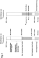
- Fig.1 a diagram in which a flow rate of a flow control valve 2 is plotted against a valve travel on a vertical axis.
- Fig.1 From the exemplary characteristic curve of a flow control valve 2 examined, it can be seen that within a range of the travel from 0 to 0.25 mm there is no flow of the heat transfer medium. In a range from 0.25 mm to about 2 mm the flow initially increases almost linearly up to about 0.7 mm and then levels off. Beyond an opening of the travel of about 2.0 mm the flow stagnates at a maximum.
- the illustration on the left explains a division of the adjustment path that the adjustment device 1 uses when the hydraulic minimum opening position has not yet been finally determined.
- the actuator 6 of the adjustment device 1 comes into contact with the flow control valve 2.
- the adjustment device 1 detects that it is coupled to a flow control valve 2 or that the adjustment device 1 is in an operational assembly state.
- the hydraulic threshold value of a valve which is assigned to the hydraulic minimum opening position, was found when examining various products of standardized, compatible flow control valves.
- the scatter of the threshold values of the valves examined results in an area in which the adjustment device 1 finds the hydraulic minimum opening position to be determined as expected along the adjustment path.
- an open range is defined in which, based on the investigation, a significant range of hydraulically limited opening positions S V can be hydraulically adjusted. Above this is an upper range of the travel in which the flow control valve 2 is essentially unthrottled, i.e. there is a barely restricted or unrestricted flow.
- the illustration on the right shows a division of the adjustment path to which the adjustment device 1 refers when the threshold value of the hydraulic minimum opening position was determined.
- the determined threshold value determines how far the sealing-effective area extends from the fully closed position Sv-min over the travel range. This knowledge enables the control system to finely regulate a small flow rate up to a critical area of a valve gap.
- the area in which the essential bandwidth of hydraulically limited opening positions S V-hydraulic can be set extends from the threshold value of the hydraulic minimum opening position S V- hydraulic-min . It is also specified that an essentially open opening position can be set in the remaining upper area of the travel range.
- An absolute value of the hydraulic minimum opening position S V-hydraulic-min varies not only depending on the valve, but also due to aging and wear of the seal.
- the value ranges of the adjustment path in the left illustration which are based on correlations of the values in the tests carried out on various available flow control valves 2, can be stored in advance in a memory of the adjustment device 1.
- the values are selected in such a way that, with any selection of a compatible, standardized flow control valve 2, the previously defined property of an effective seal or a hydraulic limitation applies with certainty or at least with a high degree of probability.
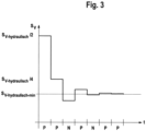
- Fig.3 shows on a vertical axis a travel in relation to a total movable distance Sv of a flow control valve 2, at which the adjustment device 1 determines the hydraulic minimum opening position S V-hydraulic-min .
- Positive results p and negative results n in relation to a detection of a flow are plotted on a horizontal time axis.
- the setting device 1 carries out the determination on the lower half of the adjustment path, in which the hydraulic minimum opening position S V-hydraulic-min is expected to be located.
- the setting device 1 of the present embodiment sets an opening position of the flow control valve 2 in a first iteration, which is assigned to half S V-hydraulic /2 of the entire distance of the adjustment path Sv.
- a blocking period of a few minutes (not shown), e.g. 5 minutes, is run through, so that a thermal inertia, which influences the response of the temperature measurement, is waited for. Then a measurement is made as to whether a Temperature of the heat transfer medium at the beginning or at the end of the consumer loop 3 changes significantly or not. If a temperature change is measured that exceeds a predetermined gradient, e.g. ⁇ 1 or ⁇ 2 K/min, it is assumed that the liquid heat transfer medium in the consumer loop 3 in the area of the temperature detection means 7 is not at rest. Rather, it is assumed that part of the heat transfer medium coming from the temperature control source 4 has now passed the flow control valve 2 and is flowing into the consumer loop 3, i.e. there is a flow, and a positive result p of the detection of a flow is determined for the first iteration.
- a predetermined gradient e.g. ⁇ 1 or ⁇ 2 K/min
- the setting device 1 sets an opening position of the flow control valve 2 in a second iteration, which is assigned to a quarter S V-hydraulic /4 of the total distance of the adjustment travel Sv.
- the processes from the first iteration are then repeated with regard to the passage of the blocking period and the temperature measurement to detect a flow, which in turn leads to a positive result p.
- the setting device 1 sets an opening position of the flow control valve 2 in the third iteration, which is assigned to an eighth S V-hydraulic /8 of the entire distance of the adjustment path Sv.
- the processes are then repeated with regard to running through the blocking period and the temperature measurement to detect a flow. No significant temperature change is measured in the third iteration.
- the setting device 1 carries out a comparison measurement within the same iteration.
- the setting device 1 temporarily opens the flow control valve 2 to a hydraulic opening position at which a flow is ensured, for example to an opening position of the previous iterations with a positive result p.
- the setting device 1 then waits for the blocking period to elapse and then carries out a second detection for verification. If a flow is detected in the comparison measurement, this means that there is no error on the part of the system. On the other hand, this also means that a lack of flow in the first recording was the result of a sealed flow cross-section at the set opening position of the third iteration. Accordingly, a negative result n is set for the third iteration.
- the adjusting device 1 sets an opening position of the flow control valve 2 in a fourth iteration that is greater than the opening position in the third iteration, by half the distance of the change before the third iteration. This value is halfway between a quarter Sv_ hydraulic /4 and an eighth S V-hydraulic /8, i.e. three sixteenths S V-hydraulic /3/16 of the total distance of the adjustment travel Sv.
- the processes are then repeated with regard to running through the blocking period and the temperature measurement to detect a flow, which in turn leads to a positive result p.
- the setting device 1 sets an opening position of the flow control valve 2 in the fifth iteration that is smaller than the opening position in the fourth iteration, by half the distance of the change before the fourth iteration. This value is five thirty-seconds S V-hydraulic /5/32 of the total distance of the adjustment travel Sv.
- the processes are then repeated with regard to running through the blocking period and the temperature measurement to detect a flow. In the first detection, no significant temperature change is measured. As in the third iteration, due to the negative detection of a flow by means of temperature measurement, the setting device 1 again carries out a second detection for verification.
- the setting device 1 temporarily sets the flow control valve 2 to a hydraulic opening position at which a flow is ensured, waits for the blocking period again and then carries out a detection of a flow. After a temperature change has occurred in the consumer loop 3 and this is verified during the second detection of a flow, it is clear that there is no external interference. A negative result n is set for the fifth iteration.
- the setting device 1 carries out a flow detection three times within each iteration that leads to a positive result p. Between the temperature measurements, the flow control valve 2 is temporarily closed for a blocking period, then reset to the corresponding opening position of the iteration, and another blocking period is waited for. In each iteration that leads to a negative result n, a flow detection takes place six times, since each detection in which no significant temperature change is measured is followed by a detection to verify a flow at a higher hydraulic opening position.
- the blocking period which is a predetermined number of a few minutes, enables better detection of a gradient of the temperature change and reduces influences on the temperature measurement due to an inertia of heat capacities of the liquid-carrying components in the temperature control system 10.
- the determination can be interrupted at any time by deactivating or switching off the setting device 1 between two temperature control requests.
- the setting device 1 continues with the next outstanding detection of the iteration in which the determination was interrupted after a subsequent activation or switching on and after a blocking period has passed.
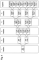
- Fig.4 shows a branching of percentage values in relation to a resolution of measurement errors.
- the values are based on a symmetrical division of value ranges, which are successively approximated to narrow down a desired value.
- Positive and negative measurements are designated with 1 and 0, with outstanding iterations designated with X.
- the illustration shows that in the present application of determining the threshold value of the hydraulic minimum opening position after five iterations, a resolution of 3.125% in relation to over the entire distance Sv. This accuracy is sufficient for the control operation of the adjustment device 1.
- the effort or duration of the determination can be limited. It only has to be ensured that at the end of the determination there is a positive result p in relation to a flow at the opening position. Otherwise, the adjustment device 1 falls back on a previous iteration, for example, or carries out another final iteration.
- the setting device 1 can decide, based on parameters such as the detected temperature difference ⁇ T Ist , a course of the same or the duration of previous activations, whether a current temperature control request contributes a small or large proportion to bringing an actual temperature closer to a target temperature. This decision is particularly relevant if there is a large need for temperature control and no flow through the flow control valve 2 was previously detected at the opening position of the interrupted iteration. Accordingly, the setting device 1 can make a decision that a continuation of the determination, which again starts at a substantially closed opening position, is temporarily postponed by one temperature control request, or is suspended every second temperature control request. As a result, the determination of a hydraulic threshold value is predominantly postponed to time periods of the control operation in which only a temperature state is maintained.
- a flow detection can be aborted again in a continued determination without the blocking period between setting an opening position and a temperature measurement to be carried out on the consumer loop 3 having expired.
- the result of the detection may not be usable and is discarded.
- a deactivation of the setting device 1, i.e. a duration between detections may not be long enough for a temperature of the heat transfer medium in the consumer loop 3 to be distinguishable from a temperature of a potentially newly flowing part of the heat transfer medium through a heat exchange.
- the setting device 1 can, in one embodiment, make a decision based on the blocking periods and activation periods that have been passed that the flow control valve 2 remains temporarily closed for the subsequent temperature control request. This ensures that even during a relatively short cycle, the temperature of the heat transfer medium in the closed consumer loop 3 has already changed significantly by heat exchange before the determination is continued, and a newly flowing part of the heat transfer medium would be detectable by a significant temperature change.
- the setting device 1 it is provided that after each temperature control request, only one interrupted or next pending iteration is carried out, including a predetermined number of flow detections, and then the control operation of the setting device 1 begins for the self-regulating adjustment of the flow control valve 2 in favor of temperature control by the temperature control system 10.
- the control operation of the setting device 1 begins for the self-regulating adjustment of the flow control valve 2 in favor of temperature control by the temperature control system 10.
- after each temperature control request only one further flow detection from an interrupted or next pending iteration is carried out before the usual control operation begins again.
- the total duration of the determination over which the iterations and their detections are carried out in a time-distributed manner therefore depends significantly on the durations of the temperature control requests and those in between, i.e. the activation durations and the deactivation durations or, in the case of a thermostat 12, on a clocking of the same.
- the adjustment device 1 starts or repeats the determination of the hydraulic threshold value when it has been dismantled from a flow control valve 2 and disconnected from a power supply. This initial situation is given when the adjustment device 1 is installed for the first time or has been removed from the flow control valve 2 in the meantime and deliberately disconnected from the power supply or reset.
- the adjustment device 1 of this embodiment can detect dismantling by a free travel of the actuator 6, which in the assembled state until contact with the pre-tensioned valve pin 23 occurs, or in the disassembled state does not occur.
- the determination of the hydraulic threshold value can be manually initiated again by the user or a craftsman.
- a predetermined signal can be entered manually, for example in the form of a timed Morse code of the signal for switching the setting device 1 on and off or activating and deactivating it.
- the adjustment device 1 repeats the determination of the hydraulic threshold value cyclically with respect to a repetition interval.
- the repetition interval is set, for example, to a predetermined number of several hundred or several thousand temperature control requests or adjustment processes on the flow control valve 2, after which a change in the valve seal is to be expected.
- the repetition interval can also be set to a predetermined number of several hundred or several thousand operating hours of the adjustment device 1.
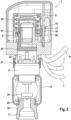
- the adjustment device 1 is mounted on a flow control valve 2.
- the adjustment device 1 is attached to the flow control valve 2 by means of a flange 27.
- the flow control valve 2 is in turn installed in a return distributor 14 in the embodiment shown here.
- the return distributor 14 has a connector 18 screwed into it, which connects the return distributor 14 to a consumer loop 3 (not shown in detail).
- the flow control valve 2 can also be installed in the return distributor 14 in another way.
- the connector 18 can also be pressed, glued, soldered, welded or otherwise attached to the return distributor 14.
- the adjustment device 1 comprises an electrically controllable actuator 6.
- the electrically controllable actuator 6 contains an actuating means 20 that can be moved in the axial direction.
- the longitudinal axis of the actuating means 20 also coincides with the longitudinal axis of the electrically controllable actuator 6.
- the actuating means 20 is arranged within the electrically controllable actuator 6, has a component that can be adjusted in length in the axial direction, for example an expansion element 21, in particular a wax cartridge, and is prestressed by a spiral spring 22 arranged coaxially and concentrically thereto.
- the length-adjustable component can also be designed as an electrical mini-actuator, although these are often not considered for cost reasons and because of the suspected noise development.
- the spiral spring 22 another suitable means, for example an annular spring package or the like, can also generate a prestress.
- the electrically controllable actuator 6 receives signals via electrical lines from a temperature detection device 7 or temperature sensor on the return flow distributor 14 (not shown in detail) regarding the outlet-side return flow temperature T return of the heat transfer medium flowing through.
- the electrically controllable actuator 6 also receives temperature signals via the lines from a temperature detection device 7 or temperature sensor on the flow distributor 13 (not shown here) regarding an inlet-side flow temperature T flow of the heat transfer medium flowing through.
- a further electrical line forms an interface 9 to a Fig.5 not, but in Fig.6 shown thermostat 12.
- Calculation means 8 contained in the adjustment device 1 process the signals received via the lines and issue corresponding commands or control signals to the electrically controllable actuator 6, based on which the expansion element 21 in the actuating means 20 is activated or deactivated. In this way, a defined adjustment path or stroke of the actuating means 20 in the axial direction is ultimately achieved.
- the actuating means 20 presses in the axial direction on an actuating pin or valve pin 23 of the flow control valve 2 and thus actuates the same.
- the longitudinal axis of the actuating means 20 and the actuating pin or valve pin 23 of the flow control valve 2 coincide.
- valve head which in the exemplary embodiment is designed as a valve plate 24, is lifted off a valve seat 25, thus defining a valve position which corresponds to a specific opening position of the flow control valve 2 or a specific valve opening cross-section.
- the position detection means 15 consists of a magnet 16 which is assigned to the electrically controllable actuator 6 via a radially outwardly projecting arm 26 and is connected to the actuating means 20. In this way, the magnet 16 moves in the axial direction parallel to the expansion element 21 or parallel to the valve plate 24, follows the same stroke or adjustment path with them, and serves as a reference for the respective stroke.
- a Hall sensor 17 arranged opposite the magnet 16 is a further component of the position detection means 15. The Hall sensor 17 detects the position as well as the movement or stroke of the magnet 16 and thereby detects the stroke of the valve plate 24 relative to the valve seat 25 and ultimately determines the cross-section of the flow control valve 2.
- the adjustment device 1 shown is available in multiple copies in the Fig.6 explained tempering system 10 is installed.
- the exemplary embodiment of the tempering system 10 according to Fig.6 contains a distributor device 11 with three adjustment devices 1, which are mounted on the respective associated flow control valve 2 by means of a respective flange 27.
- the respective flow control valves 2 are installed in the one return distributor 14.
- On the opposite side of the adjustment device 1 or on the underside of the return distributor 14 viewed in the installation direction, the latter has a connection piece 18, via which the connection to the respective consumer loop 3 is established.
- the respective consumer loop 3 forms a respective heat exchanger 30.
- a temperature detection means 7, for example a return temperature sensor 7b, is attached to the connection piece 18, in particular clipped or glued on.
- the return temperature sensor 7b detects the respective output-side return temperature T return of the heat transfer medium flowing through the respective consumer loop 3.
- the return temperature sensor 7b could also be attached at another suitable location for detecting the respective return temperature, for example immediately after the connection piece 18 on the pipe wall of the consumer loop 3 shown in line.
- the temperature control system 10 also has a flow distributor 13.
- the flow distributor 13 contains three connectors 28 for the three consumer loops 3 shown.
- a temperature detection means 7 is again attached to each connector 28, for example a flow temperature sensor 7a, in order to detect the respective inlet-side flow temperature T flow of the heat transfer medium flowing through the respective consumer loop 3.
- the flow temperature sensor 7a could also be attached to another suitable location for detecting the respective flow temperature, for example immediately after the connector 28 on the pipe wall of the consumer loop 3 shown in line.
- the flow distributor 13 is connected to the return distributor 14 via a line 29, which contains a temperature control source 4 and a pump 5.
- the pump 5 can be used to circulate the liquid heat transfer medium, which has been charged with thermal energy or possibly cooled by the temperature control source 4.
- the flowing heat transfer medium is transported by the pump 5 to the flow distributor 13, where the heat transfer medium flows into the three consumer loops 3 shown here and through these back to the return distributor 14, whereby the respective flow rate is determined by the flow cross-section of the respective flow control valve 2, which are installed in the return distributor 14. From the return distributor 14, the flowing heat transfer medium collected there flows back to the pump 5 or to the temperature control source 4.
- a thermostat 12 assigned to the respective consumer loop 3 outputs a control signal when there is a need for temperature control.
- the control signal is transmitted from the thermostat 12 to the setting device 1, for example via an interface 9, here a cable.
- the interface 9 could also be designed as a wireless connection.
- the respective setting device 1 determines the respective opening cross section of the respective flow control valve 2 by means of the respective calculation means 8 depending on the activation signal or deactivation signal of the respective thermostat 12 and the respectively assigned signals or data of the flow and return temperatures.
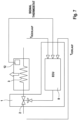
- the temperature control system 10 according to Fig.6 installed adjustment devices 1 according to Fig.5 are in Fig.7 once again illustrated in a block diagram that represents the system components for self-regulation.
- Heat or cold is emitted from the consumer loop 3 to the environment.
- a thermostat 12 in particular a room thermostat in a living room of a building, emits a signal.
- the signal from the thermostat 12 is passed on to an ECU of the adjustment device 1.
- the ECU also receives temperature signals or data, such as the return temperature T return and the flow temperature T flow.
- a calculation means 8, which contains the ECU, is set up to electrically control the actuator 6 of the adjustment device 1 (not shown in detail here) in order to realize a stroke of the valve or to set the predetermined opening position of the flow control valve 2 assigned to a specific flow cross-section.
- the opening cross section of the flow control valve 2 or its stroke is calculated based on a control difference ⁇ T control difference , whereby the control difference ⁇ T control difference to be calculated is between the temperature difference ⁇ T actual from the recorded inlet-side flow temperature T flow and the outlet-side return temperature T return and a predetermined temperature spread ⁇ T target of the outlet-side return temperature T return to the inlet-side flow temperature T flow .
- the setting device 1 further comprises a time recording means (not shown here) and a storage means which are designed to record and store a previous or current activation duration of the activation signal from the thermostat 12 and/or a deactivation duration between two activations or deactivations, wherein the calculation means 8 with the ECU contained therein is designed to variably determine the temperature spread ⁇ T target based on an activation duration and/or a deactivation duration.
- the thermostat 12 of the temperature control system 10 which is arranged in a room, can have an input means for entering a value which is indicative of a predeterminable room temperature and an interface 9 for outputting an activation signal for at least one consumer loop 3 in the room.
- the thermostat 12 of the temperature control system 10 can be configured to respond to an actual room temperature by the thermostat 12 outputting the activation signal as long as a deviation tolerance between the predefinable room temperature and the actual room temperature is exceeded.
- An activation as defined in the present disclosure is a switch-on state or a start-up from a standby mode of the setting device 1 or at least of the calculation means 8 in the setting device 1, which is supported by a continuous signal level, triggered by a signal pulse, or a control voltage applied in the form of a signal for Switching of a transistor on a power supply, a power supply directly supplied in the form of a signal or the like is triggered.
- An activation period refers by definition to the period from the beginning to the end of the correspondingly triggered switch-on state or the start-up from a standby mode or the reception period of a continuous signal level, control voltage, drive voltage or power supply, or the period between two signal pulses that cause a switch-on process and a switch-off process.
- a deactivation and a deactivation period are accordingly the complementary state and period in which there is no operation of the setting device 1 or at least no calculation of the calculation means 8 or control of the actuator 6 takes place.
- the adjustment device 1 can be designed to output the electrical control calculated by the calculation means 8 to the actuator 6 during an activation period, and to output no electrical control or a predetermined electrical control corresponding to the closed position of the flow control valve 2 to the actuator 6 during a deactivation period. Depending on the type of actuator 6, this results in the consumer loop 3 being shut off after a heating process, so that an excessive energy supply or an overshoot of the temperature control is prevented.
- the setting device 1 can be designed to switch off an electrical power supply to the calculation means 8 and/or to the setting device 1 during a deactivation period. This saves electricity during the deactivation periods, which can also extend over a summer, for example.
- the calculation means 8 can be set up to store at least one value of a previous opening position of the flow control valve 2 in the storage means. As a result, when the setting device 1 is activated, a valve position can initially be approached as a starting point, which was already determined during the previous heating periods and only needs to be adjusted differently during the current heating period.
- the storage means can contain a pre-stored reference value for the activation duration and/or a pre-stored reference value for the deactivation duration. As a result, a time period defined as comfortable for reaching a predetermined temperature is stored as a target reference value on which the self-regulation is based.
- the storage means can contain a pre-stored value range for the temperature spread. This makes it easy to ensure that the operating point of the heat exchanger 30 is selected within an energy-efficient range.
- the storage means can contain a pre-stored characteristic map with associated values of activation durations and/or deactivation durations and predetermined temperature spreads for determining the temperature spread. This allows a predetermined universal control to be implemented with lower processing power.
- the storage means can contain a pre-stored control logic for calculating the temperature spread. This allows a more individual control to be implemented.
- the setting device 1 can be set up to change the temperature spread depending on the flow temperature, and/or the setting device 1 can be set up to change a range of the temperature spread depending on the flow temperature, and/or the setting device 1 can be set up to receive further external signals with operating parameters from the temperature control system 10 via the interface 9; and the calculation means 8 can be set up to adjust the temperature spread depending on the operating parameters.
- This makes it possible to implement a control system that uses a change in the flow temperature to detect weather fluctuations or seasons and adjusts an efficient operating point accordingly or other comfort-oriented Incorporate functions that can be specified on a multifunctional room thermostat into the control system.
- a thermostat 12 and two or more consumer loops 3 or heating or cooling circuits can be arranged in a room of the building. This makes it possible to supply large rooms by means of several installed heating or cooling coils with standardized diameters and a lower overall flow resistance, which are controlled by separate setting devices 1, but the same room thermostat.
- the thermostat 12 can have a bimetal element that responds to the actual room temperature and outputs the activation signal or the deactivation signal. This results in a particularly simple, reliable and cost-effective design of the room thermostat without electronics and sensors.
- the activation signal or deactivation signal can be a binary signal that includes an on state with a signal level above a predetermined level and an off state with no signal level or a signal level below the predetermined level. This also enables a particularly simple and cost-effective implementation of signal generation and signal detection.
- a thermostat 12 can comprise a microcomputer and a temperature sensor 7a, 7b for detecting the actual room temperature; the thermostat 12 detects and stores a course of the actual room temperature while and/or after the activation signal or the deactivation signal is output; and the thermostat 12 and a setting device 1 are designed to communicate data on a course of detected actual room temperatures.
- the activation signal and/or the deactivation signal can be communicated by means of wireless interfaces 9 from a specific thermostat 12 to an associated setting device 1. This eliminates the need for wiring from the room thermostat to the setting device 1 and reduces installation costs. Furthermore, a connection between a smartphone, tablet PC or the like and a setting device 1 or a thermostat 12 can also be established via such a wireless interface 9, which provides the user with another input option for the system.
- a smaller temperature spread can be determined if at least one previous activation period is longer than a reference value, or a larger temperature spread can be determined if at least one previous activation period is shorter than the reference value. This means that the self-regulation is based on a time period that has been previously determined as comfortable to achieve a specified value.
- the temperature spread can be determined based on a history of consecutive, previous activation periods. This enables better adaptation of the self-regulation to user behavior, seasons, and the like.
- the adjustment device 1 can have a position detection means 15 which is designed to detect a current position of the actuator 6. This enables compliance with a predetermined travel distance, which is required depending on the type of actuator 6.
- the position detection means 15 can be formed from a magnet 16 and a Hall sensor 17 associated with the magnet 16. This enables precise detection and execution of a predetermined travel path.
- the actuator 6 can be provided by various types of actuators whose actuating force is based on an electromotive power, a thermal expansion, a Spring preload or the like, as long as the travel can be controlled by a control from the calculation means 8.
Landscapes
- Engineering & Computer Science (AREA)
- Physics & Mathematics (AREA)
- Mechanical Engineering (AREA)
- General Engineering & Computer Science (AREA)
- Thermal Sciences (AREA)
- Chemical & Material Sciences (AREA)
- Combustion & Propulsion (AREA)
- Automation & Control Theory (AREA)
- General Physics & Mathematics (AREA)
- Steam Or Hot-Water Central Heating Systems (AREA)
- Fluid-Pressure Circuits (AREA)
- Remote Sensing (AREA)
- Control Of Temperature (AREA)
- Temperature-Responsive Valves (AREA)
Claims (24)
- Dispositif de réglage (1) pour le réglage autorégulant d'une vanne de régulation de débit (2) d'une boucle de consommation (3) avec échangeur de chaleur (30), en particulier dans un système de régulation de température (10) pour bâtiments avec une source de régulation de température (4), un fluide caloporteur liquide et une pompe (5), le dispositif de réglage (1) présentant :un organe de réglage (6) qui est agencé de manière à pouvoir être couplé à la vanne de régulation de débit (2) de telle sorte qu'une position d'ouverture de la vanne de régulation de débit (2) peut être réglée et détectée par le dispositif de réglage (1) entre une position fermée (SV min) et une position ouverte, en particulier graduellement ou par étapes ;des moyens de détection de température (7) qui détectent une température d'arrivée côté entrée (TVorlauf) et une température de retour côté sortie (TRücklauf) du fluide caloporteur qui s'écoule par rapport à la boucle de consommation (3) ; dans lequelun moyen de calcul (8), qui est conçu pour calculer une commande de l'organe de réglage (6), qui correspond à une position d'ouverture prédéterminée - associée à une section d'écoulement déterminée - de la vanne de régulation de débit (2), de telle sorte, qu'une différence de température (ΔTIst) entre la température d'arrivée côté entrée (TVorlauf) détectée et la température de retour côté sortie (TRücklauf) est amenée à un écart de température prédéterminé (ΔTSoll) entre la température de retour côté sortie (TRücklauf) et la température d'arrivée côté entrée (TVorlauf) ; etle dispositif de réglage (1) détecte un débit à travers la vanne de régulation de débit (2) sur la base d'un changement de température du fluide caloporteur dans la boucle de consommation (3) ;caractérisé en ce quele dispositif de réglage (1) est conçu pour déterminer une position d'ouverture hydraulique minimale (SV-hydraulisch-min) de la vanne de régulation de débit (2), à laquelle un débit minimal peut être détecté, le long d'une course de réglage ; etla détermination de la position d'ouverture hydraulique minimale (SV-hydraulisch-min) comprend des itérations de différentes positions d'ouverture le long de la course de réglage de la vanne de régulation de débit (2) ;chaque itération d'une position d'ouverture de la vanne de régulation de débit (2) comprend au moins une détection du débit à travers la vanne de régulation de débit (2) ; etla détermination de la position d'ouverture hydraulique minimale (SV-hydraulisch-min) s'étend sur plusieurs demandes de régulation de température externes à la boucle de consommation (3), et les itérations manquantes de la détermination, qui sont encore en suspens après des désactivations du dispositif de réglage (1) entre les demandes de régulation de température, sont poursuivies lors de nouvelles activations du dispositif de réglage (1).
- Le dispositif de réglage (1) pour le réglage autorégulant d'une vanne de régulation de débit (2) d'une boucle de consommation (3) avec échangeur de chaleur (30), en particulier dans un système de régulation de température (10) pour des bâtiments avec une source de régulation de température (4), un fluide caloporteur liquide et une pompe (5), le dispositif de réglage (1) présentant :un organe de réglage (6) à commande électrique, qui est agencé de manière à pouvoir être couplé à la vanne de régulation de débit (2) de telle sorte qu'une position d'ouverture de la vanne de régulation de débit (2) peut être réglée et détectée par le dispositif de réglage (1) entre une position fermée (SV min) et une position ouverte, en particulier graduellement ou par étapes ;des moyens de détection de température (7) qui détectent une température d'arrivée côté entrée (TVorlauf) et une température de retour côté sortie (TRücklauf) du fluide caloporteur qui s'écoule par rapport à la boucle de consommation (3) ;un moyen de calcul (8) qui est conçu pour calculer une commande électrique de l'organe de réglage (6), qui correspond à une position d'ouverture prédéterminée - associée à une certaine section transversale d'écoulement - de la vanne de régulation de débit (2), sur la base d'une différence de régulation (ΔTRegeldifferenz), la différence de régulation à calculer (ΔTRegeldifferenz) étant comprise entreune différence de température (ΔTIst) à partir de la température d'arrivée côté entrée (TVorlauf) détectée et de la température de retour côté sortie (TRücklauf), et un écart de température prédéterminé (ΔTSoll) entre la température de retour côté sortie (TRücklauf) et la température d'arrivée côté entrée (TVorlauf) ;une interface (9) pour recevoir un signal d'activation externe pour activer le moyen de calcul (8) et/ou le dispositif de réglage (1) ; dans lequelle dispositif de réglage (1) comprend un moyen de détection de temps et un moyen de stockage agencés pour détecter et stocker une durée d'activation précédente ouactuelle du signal d'activation et/ou une durée de désactivation entre deux activations ; etle moyen de calcul (8) est adapté pour déterminer de manière variable l'écart de température (ΔTSoll) sur la base d'une durée d'activation et/ou d'une durée de désactivation ;caractérisé en ce quele dispositif de réglage (1) est adapté pour déterminer une position d'ouverture hydraulique minimale (SV-hydraulisch-min) de la vanne de régulation de débit (2), à laquelle un débit minimal peut être détecté, le long d'une course de réglage ; etle dispositif de réglage (1) détecte un débit à travers la vanne de régulation de débit (2) sur la base d'un changement de température du fluide caloporteur dans la boucle de consommation (3) ; dans lequella détermination de la position d'ouverture hydraulique minimale (SV-hydraulisch-min) comprend des itérations de différentes positions d'ouverture le long de la course de réglage de la vanne de régulation de débit (2) ;chaque itération d'une position d'ouverture de la vanne de régulation de débit (2) comprend au moins une détection du débit à travers la vanne de régulation de débit (2) ; etla détermination de la position d'ouverture hydraulique minimale (SV-hydraulisch-min) s'étend sur plusieurs demandes de régulation de température externes à la boucle de consommation (3), et les itérations manquantes de la détermination, qui sont encore en suspens après des désactivations du dispositif de réglage (1) entre les demandes de régulation de température, sont poursuivies lors de nouvelles activations du dispositif de réglage (1).
- Le dispositif de réglage (1) selon la revendication 1 ou 2, dans lequella première itération commence à une position d'ouverture hydraulique (SV-hydraulisch) à laquelle on peut s'attendre à un écoulement à travers la vanne de régulation de débit (2) ; etle dispositif de réglage (1) règle une position d'ouverture de la vanne de régulation de débit (2) pour une itération suivante avec un décalage vers une position fermée (SV-min) de la vanne de régulation de débit (2) lorsqu'un débit à travers la vanne de régulation de débit (2) est détecté.
- Le dispositif de réglage (1) selon la revendication 3, dans lequel
le dispositif de réglage (1) décale une position d'ouverture de la vanne de régulation de débit (2) pour une itération suivante dans la direction opposée à la position fermée (SV-min) de la vanne de régulation de débit (2) lorsqu'aucun débit n'est détecté à travers la vanne de régulation de débit (2). - Le dispositif de réglage (1) selon l'une des revendications 1 à 4, dans lequel
le dispositif de réglage (1) décale une position d'ouverture de la vanne de régulation de débit (2) lors d'une itération suivante d'une distance sur la course de réglage qui correspond à la moitié de la valeur de la distance décalée lors de l'itération précédente. - Le dispositif de réglage (1) selon l'une des revendications 1 à 5, dans lequel
le dispositif de réglage (1) détermine la position d'ouverture hydraulique minimale (SV-hydraulisch-min) au sein d'un nombre prédéterminé d'itérations de différentes positions d'ouverture de la vanne de régulation de débit (2). - Le dispositif de réglage (1) selon l'une des revendications 1 à 6, dans lequel
si aucun débit n'est détecté par la vanne de régulation de débit (2), une itération de la position d'ouverture correspondante comprend encore une détection du débit à une position d'ouverture supérieure de la vanne de régulation de débit (2). - Le dispositif de réglage (1) selon l'une des revendications 1 à 7, dans lequel
chaque itération comprend un nombre prédéterminé de détections du débit à travers la vanne de régulation de débit (2) à une position d'ouverture de la vanne de régulation de débit (2). - Le dispositif de réglage (1) selon l'une des revendications 1 à 8, dans lequel
entre chaque itération d'une position d'ouverture, entre chaque détection du débit à l'intérieur d'une itération d'une position d'ouverture et/ou entre une activation et une poursuite d'itérations en attente de la détermination, on passe d'abord par une période de blocage prédéterminée, pendant laquelle la vanne de régulation de débit (2) est fermée et/ou pendant laquelle aucune température n'est détectée. - Le dispositif de réglage (1) selon l'une des revendications 1 à 9, dans lequella poursuite d'une itération interrompue de la détermination de la position d'ouverture hydraulique minimale (SV-hydraulisch-min) est temporairement suspendue pour une demande de régulation de température ;si, à la position d'ouverture de l'itération interrompue, aucun débit n'a été détecté auparavant par la vanne de régulation de débit (2).
- Le dispositif de réglage (1) selon l'une des revendications 1 à 10, dans lequel
le dispositif de réglage (1) effectue la détermination de la position d'ouverture hydraulique minimale (SV-hydraulisch-min) lorsqu'il a été déconnecté d'une alimentation électrique, lorsqu'un démontage par rapport à la vanne de régulation de débit (2) a été détecté au moyen de l'organe de réglage (6) et/ou lorsqu'un schéma de commutation prédéterminé par rapport à l'activation a été détecté. - Le dispositif de réglage (1) selon l'une des revendications 1 à 11, dans lequel
le dispositif de réglage (1) effectue la détermination de la position d'ouverture hydraulique minimale (SV-hydraulisch-min) lorsqu'un intervalle de répétition prédéterminé s'écoule. - Procédé de réglage autorégulé d'un débit d'un fluide caloporteur liquide à travers une boucle de consommation (3) avec échangeur de chaleur (30) dans un système de régulation de température (10) pour bâtiments avec une source de régulation de température (4) et une pompe (5) au moyen d'un dispositif de réglage (1) pour une vanne de régulation de débit (2) ;
le procédé comprenant au moins les étapes suivantes :détecter une température de départ côté entrée (Tvoriauf) et d'une température de retour côté sortie (TRücklauf) du fluide caloporteur en circulation au niveau de la boucle de consommation (3) ;régler une position d'ouverture - associée à une section d'écoulement déterminée - de la vanne de régulation de débit (2) de telle sorte qu'une différence de température (ΔTIst) entre la température d'arrivée côté entrée (TVorlauf) détectée et la température de retour côté sortie (TRücklauf) soit amenée à un écart de température prédéterminé (ΔTSoll) entre la température de retour côté sortie (TRücklauf) et la température d'arrivée côté entrée (TVorlauf) ;caractérisé par les étapes suivantes :déterminer une position d'ouverture hydraulique minimale (SV-hydraulisch-min) de la vanne de régulation de débit (2), pour laquelle un débit minimal peut être détecté, le long d'une course de réglage ; au moyen dedétecter un débit à travers la vanne de régulation de débit (2) sur la base d'un changement de température du fluide caloporteur dans la boucle de consommation (3) ; dans lequella détermination de la position d'ouverture hydraulique minimale (SV-hydraulisch-min) comprend des itérations de différentes positions d'ouverture le long de la course de réglage de la vanne de régulation de débit (2) ;chaque itération d'une position d'ouverture de la vanne de régulation de débit (2) comprend au moins une détection du débit à travers la vanne de régulation de débit (2) ; etla détermination de la position d'ouverture hydraulique minimale (SV-hydraulisch-min) s'étend sur plusieurs demandes de régulation de température externes à la boucle de consommation (3), et les itérations manquantes de la détermination, qui sont encore en suspens après des désactivations du dispositif de réglage (1) entre les demandes de régulation de température, sont poursuivies lors de nouvelles activations du dispositif de réglage (1). - Procédé de réglage autorégulé d'un débit d'un fluide caloporteur liquide à travers une boucle de consommation (3) activable de l'extérieur avec un échangeur de chaleur (30) dans un système de régulation de température (10) pour des bâtiments avec une source de régulation de température (4) et une pompe (5) au moyen d'un dispositif de réglage (1) pour une vanne de régulation de débit (2) ;
le procédé comprenant au moins les étapes suivantes :détecter une durée d'activation précédente ou actuelle et/ou d'une durée de désactivation de la boucle de consommation (3) ;détecter une température d'arrivée côté entrée (TVorlauf) et d'une température de retour côté sortie (TRücklauf) du fluide caloporteur en circulation au niveau de la boucle de consommation (3) ;déterminer un écart de température variable (ΔTSoll) entre la température de retour côté sortie (TRücklauf) et la température d'arrivée côté entrée (TVorlauf), sur la base de la durée d'activation et/ou de la durée de désactivation ;calculer une différence de régulation (ΔTRegeldifferenz) entre une différence de température (ΔTIst) à partir de la température d'arrivée côté entrée (TVorlauf) et de la température de retour côté sortie (TRücklauf) détectées, ainsi que l'écart de température prédéterminé (ΔTSoll) ; etcalculer et régler une section de passage réglable dans la boucle de consommation (3) sur la base de la différence de régulation (ΔTRegeldifferenz) ; une position d'ouverture - associée à la section de passage calculée - de la vanne de régulation de débit (2) étant réglée dans la boucle de consommation (3) ;caractérisé par les étapes suivantes :déterminer une position d'ouverture hydraulique minimale (SV-hydraulisch-min) de la vanne de régulation de débit (2), pour laquelle un débit minimal peut être détecté, le long d'une course de réglage ; au moyen dedétecter un débit à travers la vanne de régulation de débit (2) sur la base d'un changement de température du fluide caloporteur dans la boucle de consommation (3) ; dans lequella détermination de la position d'ouverture hydraulique minimale (SV-hydraulisch-min) comprend des itérations de différentes positions d'ouverture le long de la course de réglage de la vanne de régulation de débit (2) ;chaque itération d'une position d'ouverture de la vanne de régulation de débit (2) comprend au moins une détection du débit à travers la vanne de régulation de débit (2) ; etla détermination de la position d'ouverture hydraulique minimale (SV-hydraulisch-min) s'étend sur plusieurs demandes de régulation de température externes à la boucle de consommation (3), et les itérations manquantes de la détermination, qui sont encore en suspens après des désactivations du dispositif de réglage (1) entre les demandes de régulation de température, sont poursuivies lors de nouvelles activations du dispositif de réglage (1). - Le procédé selon la revendication 13 ou 14, dans lequella première itération commence à une position d'ouverture hydraulique (SV-hydraulisch) à laquelle on peut s'attendre à un écoulement à travers la vanne de régulation de débit (2) ; etune position d'ouverture de la vanne de régulation de débit (2) est décalée vers une position fermée (SV-min) de la vanne de régulation de débit (2) pour une itération suivante lorsqu'un débit à travers la vanne de régulation de débit (2) est détecté.
- Le procédé selon la revendication 15, dans lequel
une position d'ouverture de la vanne de régulation de débit (2) est déplacée dans le sens opposé à la position de fermeture (SV-min) de la vanne de régulation de débit (2) pour une itération suivante lorsqu'aucun débit n'est détecté à travers la vanne de régulation de débit (2). - Le procédé selon l'une quelconque des revendications 13 à 16, dans lequel
une position d'ouverture de la vanne de régulation de débit (2) est décalée, lors d'une itération suivante, d'une distance sur la course de réglage qui correspond à la moitié de la valeur de la distance décalée lors de l'itération précédente. - Le procédé selon l'une quelconque des revendications 13 à 17, dans lequel
la position d'ouverture hydraulique minimale (SV-hydraulisch-min) est déterminée à l'intérieur d'un nombre prédéterminé d'itérations de différentes positions d'ouverture de la vanne de régulation de débit (2). - Le procédé selon l'une quelconque des revendications 13 à 18, dans lequel
si aucun débit n'est détecté par la vanne de régulation de débit (2), une itération de la position d'ouverture correspondante comprend encore une détection du débit à une position d'ouverture supérieure de la vanne de régulation de débit (2). - Le procédé selon l'une des revendications 13 à 19, dans lequel
chaque itération comprend un nombre prédéterminé de détections du débit à travers la vanne de régulation de débit (2) à une position d'ouverture de la vanne de régulation de débit (2). - Le procédé selon l'une des revendications 13 à 20, dans lequel
entre chaque itération d'une position d'ouverture, entre chaque détection du débit à l'intérieur d'une itération d'une position d'ouverture et/ou entre une activation et une poursuite d'itérations en attente de la détermination, on passe d'abord par une durée de blocage prédéterminée, pendant laquelle la vanne de régulation de débit (2) est fermée et/ou pendant laquelle aucune température n'est détectée. - Le procédé selon l'une des revendications 13 à 21, dans lequella poursuite d'une itération interrompue de la détermination de la position d'ouverture hydraulique minimale (SV-hydraulisch-min) est temporairement suspendue pour une demande de régulation de température ;si, à la position d'ouverture de l'itération interrompue, aucun débit n'a été détecté auparavant par la vanne de régulation de débit (2).
- Le procédé selon l'une des revendications 13 à 22, dans lequel
la détermination de la position d'ouverture hydraulique minimale (SV-hydraulisch-min) est effectuée lorsque le dispositif de réglage (1) a été déconnecté d'une alimentation électrique, lorsqu'un démontage par rapport à la vanne de régulation de débit (2) a été détecté et/ou lorsqu'un schéma de commutation prédéterminé par rapport à l'activation a été détecté. - Le procédé selon l'une des revendications 13 à 23, dans lequel
la détermination de la position d'ouverture hydraulique minimale (SV-hydraulisch-min) est effectuée lorsqu'un intervalle de répétition prédéterminé s'écoule.
Applications Claiming Priority (2)
| Application Number | Priority Date | Filing Date | Title |
|---|---|---|---|
| DE102019120126.8A DE102019120126B4 (de) | 2019-07-25 | 2019-07-25 | Einstellvorrichtung und Verfahren zur Ermittlung eines hydraulischen Schwellwerts eines Ventils |
| PCT/EP2020/063334 WO2021013398A1 (fr) | 2019-07-25 | 2020-05-13 | Dispositif de réglage et procédé pour déterminer une valeur-seuil hydraulique d'une vanne |
Publications (3)
| Publication Number | Publication Date |
|---|---|
| EP4004448A1 EP4004448A1 (fr) | 2022-06-01 |
| EP4004448C0 EP4004448C0 (fr) | 2024-09-25 |
| EP4004448B1 true EP4004448B1 (fr) | 2024-09-25 |
Family
ID=71078482
Family Applications (1)
| Application Number | Title | Priority Date | Filing Date |
|---|---|---|---|
| EP20731796.7A Active EP4004448B1 (fr) | 2019-07-25 | 2020-05-13 | Dispositif de réglage et procédé pour déterminer une valeur-seuil hydraulique d'une vanne |
Country Status (6)
| Country | Link |
|---|---|
| EP (1) | EP4004448B1 (fr) |
| KR (1) | KR102566473B1 (fr) |
| CN (1) | CN114207548B (fr) |
| CA (1) | CA3142432C (fr) |
| DE (1) | DE102019120126B4 (fr) |
| WO (1) | WO2021013398A1 (fr) |
Families Citing this family (1)
| Publication number | Priority date | Publication date | Assignee | Title |
|---|---|---|---|---|
| IT202100011261A1 (it) | 2021-05-03 | 2022-11-03 | Fimcim Spa | Impianto di condizionamento e/o riscaldamento e processo di controllo di detto impianto |
Family Cites Families (15)
| Publication number | Priority date | Publication date | Assignee | Title |
|---|---|---|---|---|
| CN1319750A (zh) * | 2000-01-31 | 2001-10-31 | 袁昌平 | 一种直热式燃气热水器恒温系统 |
| CN100418817C (zh) * | 2003-07-31 | 2008-09-17 | 大陆-特韦斯贸易合伙股份公司及两合公司 | 确定调节设备的致动电流的方法 |
| US7966838B2 (en) * | 2006-12-21 | 2011-06-28 | Carrier Corporation | Suction modulation valve for refrigerant system with adjustable opening for pulse width modulation control |
| US20090314484A1 (en) * | 2008-06-18 | 2009-12-24 | Akz Technologies Llc | Standalone flow rate controller for controlling flow rate of cooling or heating fluid through a heat exchanger |
| US8915262B2 (en) * | 2011-08-09 | 2014-12-23 | Hitachi Metals, Ltd. | Mass flow controller algorithm with adaptive valve start position |
| JP5868671B2 (ja) * | 2011-11-28 | 2016-02-24 | 三菱日立パワーシステムズ株式会社 | 弁制御装置、ガスタービン、及び弁制御方法 |
| CH706146A2 (de) * | 2012-02-29 | 2013-08-30 | Oblamatik Ag | Verfahren und System zum Temperieren von Bauteilen. |
| CN102679498B (zh) * | 2012-05-14 | 2014-06-04 | 广州市设计院 | 一种自校正变参量风机盘管温控方法及专用装置 |
| DE102012020750B4 (de) * | 2012-10-23 | 2017-02-16 | Michael Sparn | Verfahren zur Optimierung eines thermischen und eines hydraulischen Abgleichs in einer Temperieranlage |
| DK2871424T3 (en) * | 2013-11-07 | 2018-10-29 | Grundfos Holding As | Control method for a heating and / or cooling system and distributor arrangement for a heating and / or cooling system |
| CN106079333B (zh) * | 2016-06-12 | 2018-05-18 | 广州市香港科大霍英东研究院 | 基于无模型优化的注塑机开模参数自动调节方法 |
| EP3412978B1 (fr) * | 2017-06-09 | 2020-03-04 | REHAU AG + Co | Procédé de commande d'un système de refroidissement et/ou de chauffage |
| DE102017115376A1 (de) * | 2017-07-10 | 2019-01-10 | Rehau Ag + Co | Verfahren zur Durchführung eines hydraulischen Abgleichs eines Heizungs- und/oder Kühlungssystems wie z. B. ein Gebäude |
| DE102017123560B4 (de) * | 2017-10-10 | 2024-09-12 | Eut Edelstahl Umformtechnik Gmbh | Selbstregulierende Einstellvorrichtung für ein Durchflussregelventil |
| CN107917089B (zh) * | 2017-11-17 | 2019-04-26 | 上海交通大学 | 循环水泵泵叶开度优化调节方法 |
-
2019
- 2019-07-25 DE DE102019120126.8A patent/DE102019120126B4/de active Active
-
2020
- 2020-05-13 KR KR1020227006355A patent/KR102566473B1/ko active Active
- 2020-05-13 CA CA3142432A patent/CA3142432C/fr active Active
- 2020-05-13 EP EP20731796.7A patent/EP4004448B1/fr active Active
- 2020-05-13 WO PCT/EP2020/063334 patent/WO2021013398A1/fr not_active Ceased
- 2020-05-13 CN CN202080053249.2A patent/CN114207548B/zh active Active
Also Published As
| Publication number | Publication date |
|---|---|
| KR102566473B1 (ko) | 2023-08-11 |
| CN114207548B (zh) | 2023-05-16 |
| CN114207548A (zh) | 2022-03-18 |
| DE102019120126B4 (de) | 2021-08-05 |
| EP4004448A1 (fr) | 2022-06-01 |
| EP4004448C0 (fr) | 2024-09-25 |
| CA3142432A1 (fr) | 2021-01-28 |
| WO2021013398A1 (fr) | 2021-01-28 |
| KR20220035972A (ko) | 2022-03-22 |
| DE102019120126A1 (de) | 2021-01-28 |
| CA3142432C (fr) | 2023-10-24 |
Similar Documents
| Publication | Publication Date | Title |
|---|---|---|
| DE102017123560B4 (de) | Selbstregulierende Einstellvorrichtung für ein Durchflussregelventil | |
| EP1936288B1 (fr) | Procédé et système destinés à la détection d'un équilibrage hydraulique d'une installation de chauffage | |
| EP3936770B1 (fr) | Système de chauffage à équilibrage hydraulique adaptatif automatique | |
| EP1645928B1 (fr) | Procédé de détermination de l'état d'alimentation d'une surface chauffante et régulateur d'état d'alimentation | |
| DE102008045775A1 (de) | Verfahren zur Überwachung der Funktionsfähigkeit eines Stellgeräts mit pneumatischem Antrieb und Magnetventil | |
| EP0729086A2 (fr) | Procédé et dispositif pour réguler un système de chauffage par température basse | |
| DE10057361A1 (de) | Verfahren zum Steuern einer Heizungsanlage und Heizungsanlage | |
| DE102007045513B4 (de) | Verfahren und Vorrichtung zum Zumessen eines Fluids | |
| EP3874338B1 (fr) | Procédé de fonctionnement d'une soupape, unité de commande électronique associée et entraînement de soupape | |
| EP4004448B1 (fr) | Dispositif de réglage et procédé pour déterminer une valeur-seuil hydraulique d'une vanne | |
| DE102014102275A1 (de) | Verfahren zur Regelung einer Heizungs- und/oder Klimaanlage und Heizungs- und/oder Klimaanlage hierzu | |
| DE102022202279A1 (de) | Elektrohydraulische Regelungsvorrichtung und verstellbares hydraulisches Pumpensystem | |
| EP4004447B1 (fr) | Dispositif de réglage et procédé permettant le réglage fin amélioré d'un jeu de soupape | |
| DE10108852C1 (de) | Raumtemperaturregelung | |
| EP3874207B1 (fr) | Dispositif de réglage par régulation automatique pour une soupape de régulation de débit, et procédé de réglage par régulation automatique | |
| DE102012112710A1 (de) | System und Verfahren zur Regelung eines Ventils | |
| DE102015113340A1 (de) | Heizungsanlage und Verfahren zum Betreiben einer Heizungsanlage | |
| EP0175857B1 (fr) | Dispositif pour la mesure de débit volumétrique d'un milieu fluide par le regulateur d'un circuit de contrôle et l'usage pour contrôler et/ou mesurer la chaleur | |
| EP3425474B1 (fr) | Procédé de commande d'un entraînement thermoélectrique à 2 points d'une vanne d'un système de chauffage et/ou de refroidissement | |
| EP3431888B1 (fr) | Procédé de mise en uvre d'un équilibre hydraulique d'un système de chauffage et/ou de refroidissement | |
| WO2023217752A1 (fr) | Procédé de surveillance et/ou de commande d'un système de chauffage | |
| EP4692650A1 (fr) | Tête thermostatique et procédé de détermination d'un point d'ouverture d'une soupape de radiateur | |
| EP4509769A1 (fr) | Procédé de réglage d'une soupape de décharge pour un système de chauffage | |
| DE102018127385A1 (de) | Einstellvorrichtung mit einer optischen Datenschnittstelle, optisches Datenübertragungssystem und Verfahren | |
| DE102005032834A1 (de) | Verfahren und Heizkostenverteiler zur Erfassung des Heizwärmeverbrauchs bei Heizkörpern |
Legal Events
| Date | Code | Title | Description |
|---|---|---|---|
| STAA | Information on the status of an ep patent application or granted ep patent |
Free format text: STATUS: UNKNOWN |
|
| STAA | Information on the status of an ep patent application or granted ep patent |
Free format text: STATUS: THE INTERNATIONAL PUBLICATION HAS BEEN MADE |
|
| PUAI | Public reference made under article 153(3) epc to a published international application that has entered the european phase |
Free format text: ORIGINAL CODE: 0009012 |
|
| STAA | Information on the status of an ep patent application or granted ep patent |
Free format text: STATUS: REQUEST FOR EXAMINATION WAS MADE |
|
| 17P | Request for examination filed |
Effective date: 20220110 |
|
| AK | Designated contracting states |
Kind code of ref document: A1 Designated state(s): AL AT BE BG CH CY CZ DE DK EE ES FI FR GB GR HR HU IE IS IT LI LT LU LV MC MK MT NL NO PL PT RO RS SE SI SK SM TR |
|
| DAV | Request for validation of the european patent (deleted) | ||
| DAX | Request for extension of the european patent (deleted) | ||
| GRAP | Despatch of communication of intention to grant a patent |
Free format text: ORIGINAL CODE: EPIDOSNIGR1 |
|
| STAA | Information on the status of an ep patent application or granted ep patent |
Free format text: STATUS: GRANT OF PATENT IS INTENDED |
|
| INTG | Intention to grant announced |
Effective date: 20240426 |
|
| GRAS | Grant fee paid |
Free format text: ORIGINAL CODE: EPIDOSNIGR3 |
|
| GRAA | (expected) grant |
Free format text: ORIGINAL CODE: 0009210 |
|
| STAA | Information on the status of an ep patent application or granted ep patent |
Free format text: STATUS: THE PATENT HAS BEEN GRANTED |
|
| AK | Designated contracting states |
Kind code of ref document: B1 Designated state(s): AL AT BE BG CH CY CZ DE DK EE ES FI FR GB GR HR HU IE IS IT LI LT LU LV MC MK MT NL NO PL PT RO RS SE SI SK SM TR |
|
| REG | Reference to a national code |
Ref country code: GB Ref legal event code: FG4D Free format text: NOT ENGLISH |
|
| RIN1 | Information on inventor provided before grant (corrected) |
Inventor name: GOTTSTEIN, DOMINIK Inventor name: PACKE, CHRISTOPH Inventor name: LANDMESSER, BENJAMIN Inventor name: STRAUB, PHILIPP Inventor name: STRAUB, THOMAS |
|
| REG | Reference to a national code |
Ref country code: CH Ref legal event code: EP |
|
| REG | Reference to a national code |
Ref country code: DE Ref legal event code: R096 Ref document number: 502020009331 Country of ref document: DE |
|
| REG | Reference to a national code |
Ref country code: IE Ref legal event code: FG4D Free format text: LANGUAGE OF EP DOCUMENT: GERMAN |
|
| U01 | Request for unitary effect filed |
Effective date: 20241009 |
|
| U07 | Unitary effect registered |
Designated state(s): AT BE BG DE DK EE FI FR IT LT LU LV MT NL PT RO SE SI Effective date: 20241029 |
|
| PG25 | Lapsed in a contracting state [announced via postgrant information from national office to epo] |
Ref country code: NO Free format text: LAPSE BECAUSE OF FAILURE TO SUBMIT A TRANSLATION OF THE DESCRIPTION OR TO PAY THE FEE WITHIN THE PRESCRIBED TIME-LIMIT Effective date: 20241225 |
|
| PG25 | Lapsed in a contracting state [announced via postgrant information from national office to epo] |
Ref country code: GR Free format text: LAPSE BECAUSE OF FAILURE TO SUBMIT A TRANSLATION OF THE DESCRIPTION OR TO PAY THE FEE WITHIN THE PRESCRIBED TIME-LIMIT Effective date: 20241226 |
|
| PG25 | Lapsed in a contracting state [announced via postgrant information from national office to epo] |
Ref country code: RS Free format text: LAPSE BECAUSE OF FAILURE TO SUBMIT A TRANSLATION OF THE DESCRIPTION OR TO PAY THE FEE WITHIN THE PRESCRIBED TIME-LIMIT Effective date: 20241225 |
|
| PG25 | Lapsed in a contracting state [announced via postgrant information from national office to epo] |
Ref country code: RS Free format text: LAPSE BECAUSE OF FAILURE TO SUBMIT A TRANSLATION OF THE DESCRIPTION OR TO PAY THE FEE WITHIN THE PRESCRIBED TIME-LIMIT Effective date: 20241225 Ref country code: NO Free format text: LAPSE BECAUSE OF FAILURE TO SUBMIT A TRANSLATION OF THE DESCRIPTION OR TO PAY THE FEE WITHIN THE PRESCRIBED TIME-LIMIT Effective date: 20241225 Ref country code: GR Free format text: LAPSE BECAUSE OF FAILURE TO SUBMIT A TRANSLATION OF THE DESCRIPTION OR TO PAY THE FEE WITHIN THE PRESCRIBED TIME-LIMIT Effective date: 20241226 |
|
| PG25 | Lapsed in a contracting state [announced via postgrant information from national office to epo] |
Ref country code: IS Free format text: LAPSE BECAUSE OF FAILURE TO SUBMIT A TRANSLATION OF THE DESCRIPTION OR TO PAY THE FEE WITHIN THE PRESCRIBED TIME-LIMIT Effective date: 20250125 |
|
| PG25 | Lapsed in a contracting state [announced via postgrant information from national office to epo] |
Ref country code: SM Free format text: LAPSE BECAUSE OF FAILURE TO SUBMIT A TRANSLATION OF THE DESCRIPTION OR TO PAY THE FEE WITHIN THE PRESCRIBED TIME-LIMIT Effective date: 20240925 |
|
| PG25 | Lapsed in a contracting state [announced via postgrant information from national office to epo] |
Ref country code: ES Free format text: LAPSE BECAUSE OF FAILURE TO SUBMIT A TRANSLATION OF THE DESCRIPTION OR TO PAY THE FEE WITHIN THE PRESCRIBED TIME-LIMIT Effective date: 20240925 |
|
| PG25 | Lapsed in a contracting state [announced via postgrant information from national office to epo] |
Ref country code: PL Free format text: LAPSE BECAUSE OF FAILURE TO SUBMIT A TRANSLATION OF THE DESCRIPTION OR TO PAY THE FEE WITHIN THE PRESCRIBED TIME-LIMIT Effective date: 20240925 Ref country code: CZ Free format text: LAPSE BECAUSE OF FAILURE TO SUBMIT A TRANSLATION OF THE DESCRIPTION OR TO PAY THE FEE WITHIN THE PRESCRIBED TIME-LIMIT Effective date: 20240925 |
|
| PG25 | Lapsed in a contracting state [announced via postgrant information from national office to epo] |
Ref country code: SK Free format text: LAPSE BECAUSE OF FAILURE TO SUBMIT A TRANSLATION OF THE DESCRIPTION OR TO PAY THE FEE WITHIN THE PRESCRIBED TIME-LIMIT Effective date: 20240925 |
|
| U20 | Renewal fee for the european patent with unitary effect paid |
Year of fee payment: 6 Effective date: 20250326 |
|
| PLBE | No opposition filed within time limit |
Free format text: ORIGINAL CODE: 0009261 |
|
| STAA | Information on the status of an ep patent application or granted ep patent |
Free format text: STATUS: NO OPPOSITION FILED WITHIN TIME LIMIT |
|
| 26N | No opposition filed |
Effective date: 20250626 |
|
| REG | Reference to a national code |
Ref country code: CH Ref legal event code: H13 Free format text: ST27 STATUS EVENT CODE: U-0-0-H10-H13 (AS PROVIDED BY THE NATIONAL OFFICE) Effective date: 20251223 |
|
| PG25 | Lapsed in a contracting state [announced via postgrant information from national office to epo] |
Ref country code: HR Free format text: LAPSE BECAUSE OF FAILURE TO SUBMIT A TRANSLATION OF THE DESCRIPTION OR TO PAY THE FEE WITHIN THE PRESCRIBED TIME-LIMIT Effective date: 20240925 |
|
| PG25 | Lapsed in a contracting state [announced via postgrant information from national office to epo] |
Ref country code: CH Free format text: LAPSE BECAUSE OF NON-PAYMENT OF DUE FEES Effective date: 20250531 |
|
| GBPC | Gb: european patent ceased through non-payment of renewal fee |
Effective date: 20250513 |
|
| PG25 | Lapsed in a contracting state [announced via postgrant information from national office to epo] |
Ref country code: MC Free format text: LAPSE BECAUSE OF FAILURE TO SUBMIT A TRANSLATION OF THE DESCRIPTION OR TO PAY THE FEE WITHIN THE PRESCRIBED TIME-LIMIT Effective date: 20240925 |
|
| PG25 | Lapsed in a contracting state [announced via postgrant information from national office to epo] |
Ref country code: GB Free format text: LAPSE BECAUSE OF NON-PAYMENT OF DUE FEES Effective date: 20250513 |
|
| PG25 | Lapsed in a contracting state [announced via postgrant information from national office to epo] |
Ref country code: IE Free format text: LAPSE BECAUSE OF NON-PAYMENT OF DUE FEES Effective date: 20250513 |