EP4004569B1 - Procédé ainsi que dispositif pour vérifier l'isolation d'un composant électrique, en particulier d'un faisceau de câbles haute tension - Google Patents
Procédé ainsi que dispositif pour vérifier l'isolation d'un composant électrique, en particulier d'un faisceau de câbles haute tension Download PDFInfo
- Publication number
- EP4004569B1 EP4004569B1 EP20734345.0A EP20734345A EP4004569B1 EP 4004569 B1 EP4004569 B1 EP 4004569B1 EP 20734345 A EP20734345 A EP 20734345A EP 4004569 B1 EP4004569 B1 EP 4004569B1
- Authority
- EP
- European Patent Office
- Prior art keywords
- test
- sheath
- insulation
- component
- wall
- Prior art date
- Legal status (The legal status is an assumption and is not a legal conclusion. Google has not performed a legal analysis and makes no representation as to the accuracy of the status listed.)
- Active
Links
Images
Classifications
-
- G—PHYSICS
- G01—MEASURING; TESTING
- G01R—MEASURING ELECTRIC VARIABLES; MEASURING MAGNETIC VARIABLES
- G01R31/00—Arrangements for testing electric properties; Arrangements for locating electric faults; Arrangements for electrical testing characterised by what is being tested not provided for elsewhere
- G01R31/12—Testing dielectric strength or breakdown voltage ; Testing or monitoring effectiveness or level of insulation, e.g. of a cable or of an apparatus, for example using partial discharge measurements; Electrostatic testing
- G01R31/16—Construction of testing vessels; Electrodes therefor
-
- G—PHYSICS
- G01—MEASURING; TESTING
- G01R—MEASURING ELECTRIC VARIABLES; MEASURING MAGNETIC VARIABLES
- G01R31/00—Arrangements for testing electric properties; Arrangements for locating electric faults; Arrangements for electrical testing characterised by what is being tested not provided for elsewhere
- G01R31/12—Testing dielectric strength or breakdown voltage ; Testing or monitoring effectiveness or level of insulation, e.g. of a cable or of an apparatus, for example using partial discharge measurements; Electrostatic testing
- G01R31/1227—Testing dielectric strength or breakdown voltage ; Testing or monitoring effectiveness or level of insulation, e.g. of a cable or of an apparatus, for example using partial discharge measurements; Electrostatic testing of components, parts or materials
- G01R31/1263—Testing dielectric strength or breakdown voltage ; Testing or monitoring effectiveness or level of insulation, e.g. of a cable or of an apparatus, for example using partial discharge measurements; Electrostatic testing of components, parts or materials of solid or fluid materials, e.g. insulation films, bulk material; of semiconductors or LV electronic components or parts; of cable, line or wire insulation
- G01R31/1272—Testing dielectric strength or breakdown voltage ; Testing or monitoring effectiveness or level of insulation, e.g. of a cable or of an apparatus, for example using partial discharge measurements; Electrostatic testing of components, parts or materials of solid or fluid materials, e.g. insulation films, bulk material; of semiconductors or LV electronic components or parts; of cable, line or wire insulation of cable, line or wire insulation, e.g. using partial discharge measurements
Definitions
- the invention relates to a method and a device for testing the insulation of an electrical component, in particular a cable, especially a cable set and in particular a high-voltage cable (HV cable) or a high-voltage cable set (HV cable set).
- a cable especially a cable set and in particular a high-voltage cable (HV cable) or a high-voltage cable set (HV cable set).
- HV cable high-voltage cable
- HV cable set high-voltage cable set
- Cable assemblies generally consist of several interconnected components.
- cable harnesses for example, several individual lines or individual cables are typically combined and typically form a branched structure.
- the individual lines or cables are pre-assembled, ie they already have contact elements or plugs at the ends.
- Individual cables can also be connected to one another within the cable set, for example via distributors or connectors, etc.
- a functional test is generally carried out at the end of a cable harness production. Among other things, the integrity of the insulation of the cable set is checked during this test. This test, also known as the "insulation test", ensures, for example, that no live parts of the conductor have penetrated an insulating jacket and/or that the integrity of the insulation is ensured. In the case of shielded HV cables, an insulation resistance of the insulation can be measured against the shield attached to the inner conductor.
- From the DE 33 09 658 A1 shows a device for optically testing the dielectric strength of an electrical insulation, in which a plate with a lateral sealing element is placed on the insulation to be tested and a test space is also enclosed between the plate and the insulation to be tested, which is evacuated, for example, or filled with a test gas is filled.
- From the DE 28 016 49 A1 shows a test device in which a cable to be tested is placed in a tube surrounding the cable and also filled with a test gas.
- From the DE 10 2016 116 695 A1 discloses a method of inspecting a wire harness by putting a cuff on a wire in an inspecting section to inspect whether a specific test line of the wire harness is in the inspecting section.
- test clamp for checking a cable set can be found.
- the test tongs have two arms that are attached to one another and grips the cable set to be tested. There is a test room above the front seals formed, in which a test medium is introduced. To test the cable, the test clamp is successively guided along the cable.
- the invention is based on the object of specifying a method and a device for testing the insulation of an electrical component, in particular a HV cable set.
- the object directed to the method is solved by a method for testing the insulation of an electrical component with the features of claim 1.
- the electrical component is in particular a cable, specifically a cable set, in particular a high-voltage cable (HV cable), specifically a high-voltage cable set (HV cable set).
- HV cable high-voltage cable
- HV cable set high-voltage cable set
- the method described below and the device are also suitable for testing other electrical components, for example an electrical device in which electrical components are surrounded by an insulating housing.
- the electrical component generally has an electrical core which is surrounded by the insulation to be tested.
- the insulation is, for example, a cable jacket and/or an insulating housing.
- a voltage is applied to the electrical core.
- the electrical core is in particular a conductor which is surrounded by a cable sheath as insulation.
- the electrical core is formed by the multiple conductors, each of which is surrounded by a conductor insulation (core sheath) and each forms a core.
- the multi-core cable is surrounded by a common cable sheath, which is at least part of the insulation to be tested.
- test case in which the component to be tested is placed during the test.
- the test envelope has a wall made of a flexible and electrically conductive material, the flexibility of the test envelope being such that it lies flat against the insulation so that it accommodates an outer contour of the insulation and simulates it.
- a test voltage is applied to the electrical core and a suitable measurement is used to determine whether the insulation meets the quality requirements or whether the insulation is defective.
- the test sleeve is therefore used in the manner of an electrode.
- a check is made as to whether a leakage current is flowing away via the measuring sleeve and, in particular, how high this leakage current is, in order to decide whether it exceeds a critical value.
- the potential applied to the measuring sleeve is measured, for example with respect to a reference potential. In general, therefore, an electrical property of the test envelope is measured and, based on the measurement result, it is determined whether the insulation meets the quality requirements or is defective.
- Another advantage of the measuring method with this flexible test sleeve is that no additional media such as salt water or special test gases are introduced, which are then arranged in a space between the test sleeve, which serves as an electrode, and the insulation. Therefore, additional test media such as test gas or test liquid are not used.
- the test envelope lies directly and flat against the insulation.
- the test envelope is a test bag that holds the component to be tested.
- a “test pocket” is generally understood to mean that it has two opposite envelope surfaces which—at least when the test method is being carried out or alternatively permanently—are connected to one another on at least three edge sides.
- the edge sides can preferably be closed, in particular reversibly, by means of a closure element.
- the test bag therefore defines a closed test space, which only has an opening towards one edge side. This can preferably also be closed during the testing process.
- the component lies in the test pocket, preferably completely.
- the test pocket therefore forms a closed test space, which has the opening, which in particular can be closed, on only one side.
- At least one end of the component preferably several ends of the component, is brought out of this opening for connection to a voltage supply, specifically for connection to the test voltage.
- the led-out ends are specially formed by contact terminals.
- the component lies completely in the test case and the voltage connection is made via the opening using a connection element.
- the test envelope accommodates the component at least largely completely.
- “largely complete” is understood to mean that the component to be tested lies completely in the test envelope, with the exception of any connection areas of the component to be tested.
- the connection areas of the component, which are led out of the test envelope, are used to apply the test voltage.
- the ends that are pre-assembled with a plug, for example, are brought out, the rest of the cable set, i.e. for example at least 90% (of the entire cable length) is accommodated in the test case.
- the complete component to be tested, in particular the HV cable set is preferably in the test case, especially in the test bag.
- test method described below with the special test envelope can also be used for test situations in which the component is alternatively only partially, for example in sections, in the test envelope, which in turn can be designed as a test pocket.
- a cable set is understood to mean that a number of individual cables or lines are connected to one another to form a unit and typically form a branched structure.
- the individual cables are often connected to one another, for example via distributors or connectors, or are at least pre-assembled at the end with contact elements and/or plug elements.
- a high-voltage cable or cable set is understood to mean that the respective cable or cable set is designed for high voltages of in particular more than 250 volts, preferably more than 500 volts or even more than 1,000 volts and preferably up to a maximum of 1,500 to 2,000 volts is designed.
- the HV cables are typically designed to conduct high currents and accordingly have a large conductor cross section of, for example, several square millimeters (mm 2 ), for example more than 2.5 mm 2 .
- Such HV cable harnesses are used, for example, in the automotive industry, specifically for motor vehicles with an electric drive motor (electric vehicle or hybrid vehicle).
- the individual HV cable is typically a single-wire line, which is either provided with a shield as the outer conductor in the manner of a coaxial line, or in which there is no shield.
- the HV cable consists, for example, only of the conductor and the insulation surrounding it, which thus forms a core or cable sheath.
- the individual HV cable can also be a multi-core cable in which the individual cable cores are surrounded by a common insulating jacket as insulation.
- a negative pressure is generated in the test envelope with the component lying therein, compared to the pressure prevailing outside the test envelope.
- the test envelope ie its wall, nestles against the insulation and touches the insulation over a large area, in particular over the entire area.
- “Large area” means that more than 60%, preferably more than 80% and in particular more than 90% of the insulation is in contact with the test envelope. This means that only a small part of the surface of the insulation to be tested is not touched by the test envelope.
- low pressure is understood to mean a negative pressure of at least 150 hPa (150 mbar), preferably of at least 250 hPa.
- the negative pressure is preferably a maximum of 1000 hPa (1 bar) and specifically a maximum of 500 hPa.
- a negative pressure in the range of 200 hPa and 500 hPa is preferably set.
- the test envelope preferably has a suction connection, to which a suction line is connected in order to generate the negative pressure.
- the suction connection is, for example, a sleeve-like or bushing-like element, which is introduced into the wall in particular in a sealing manner and enables a flow path into the interior of the test casing.
- the socket typically consists of a material that is significantly stiffer than the wall, specifically plastic.
- the suction connection preferably has a closure valve that acts in particular automatically, such as a membrane closure, which prevents air from flowing in after the negative pressure has been generated.
- test envelope can also be closed airtight when the component is inserted.
- a closure element can be dispensed with, since when a negative pressure is applied, opposite wall areas of the test envelope are pulled together and are then possibly even self-sealing.
- one or more separate closure elements are preferably provided for the particularly airtight closure.
- the edge areas of the test case can be closed with a zip fastener or with adhesive or adhesive strips.
- This at least one closure element is in particular an integral part of the wall, ie firmly connected to it.
- necessary bushings for example for the bushing of the end areas of the cable harness to be tested, are expediently designed as airtight bushings.
- preferably half-shell-like reinforcements or sealing elements are integrated into the test envelope, for example, which are then placed around the cable section that has been passed through and enclose it in a sealing manner.
- fixing clamps etc. attached to the outside edge can be provided, which press the test sleeve against the partial area of the cable that has been passed through.
- the test envelope preferably has a measuring connection for connecting a measuring device, by means of which the electrical property is measured, in particular the test envelope is checked for an applied voltage.
- the measuring connection is, for example, a contact bolt, a contact socket or some other plug-in element.
- the component generally has at least one contact connection to which a voltage is applied when used as intended.
- a cable or a cable set is a contact element attached at the end, in particular a cable (set) plug.
- the cable set usually has a number of such cable set plugs.
- At least one or more such contact connections lie in the test case during the test. At least one connection end of the component to be tested is therefore in the test case. As a result, the insulation resistance of the connected contact element is checked at the same time during the test.
- connection element is preferably formed for this purpose, which is integrated into the test envelope and to which the component located inside the test envelope, specifically the cable harness, can be connected via the contact connection.
- the connection element is in particular a plug element, which therefore forms a mating plug for the cable harness plug. This eliminates the need to remove a section of the component to be tested from the test envelope.
- the component, especially the cable set is therefore connected to the integrated connection element inside the test case via a special plug connection.
- connection element itself is in turn preferably sealed and guided through the wall of the test envelope and has a connection contact on the outside, for example a plug-in contact for applying the test voltage.
- test voltage is generally applied via the contact connections of the component either directly or indirectly via the integrated connection element.
- the wall is generally a highly flexible, specifically film-like or also material-like covering. This has a low level of rigidity, so that it can easily adapt to the outer contour of the component to be tested, especially when the vacuum is applied.
- the wall has a wall thickness or thickness in the range of up to a maximum of 300 ⁇ m, preferably up to a maximum of 200 ⁇ m or up to a maximum of 100 ⁇ m.
- the wall has a film-like character, as is generally known, for example, in the packaging of food, specifically in the vacuum-tight packaging of food, for example by means of so-called freezer bags.
- the wall of the test envelope is preferably formed by a conductive plastic film or by a plastic film provided with a conductive coating.
- the wall has, in particular, a non-conductive film and a further, conductive layer.
- the conductive layer is formed, in particular, as a fabric or a mesh made of conductive fibers/threads, for example extremely fine wires.
- the conductive layer is oriented inwards towards the interior of the test envelope and is formed outwards by a film forming a gas-tight outer layer.
- the measuring connection is, for example, through a lead through the film Contact element realized, which is attached to the wall.
- this is a mechanically fastened element, for example a contact screw.
- the contact element is preferably passed airtight through the outer layer formed by the film. In principle, this principle of contacting with a contact element passed through the wall can also be used when using a conductive film or a film provided with a conductive coating.
- the test envelope is designed in the initial state as a single-layer film, for example, with the component to be tested first being placed on a first part, namely a lower part of the test envelope, and then a further part, hereinafter referred to as the upper part. placed over the component to be tested.
- a first part namely a lower part of the test envelope
- a further part hereinafter referred to as the upper part.
- the closure element or closure elements run in particular along the open edge sides, for example in a U-shape.
- the component to be tested remains in the test case after the test, and this is used as a protective cover or also as transport packaging, for example like a disposable item.
- the test sleeve fulfills a dual function, namely on the one hand for testing the cable set and as a transport packaging to an intended place of use.
- the test sleeve is alternatively used in the manner of a circulatory system for testing other components.
- the device has the test envelope and preferably also a measuring device and preferably also a vacuum pump.
- Figure 1A shows a test envelope 2, which in the illustrated embodiment has an unfolded film layer 6 with a first part, hereinafter referred to as the lower part 6A, and a further part, hereinafter referred to as the upper part 6B.
- the component in the form of a cable harness 4 rests on the lower part 6A.
- the two parts 6A, 6B are connected as indicated by the arrow in Figure 1A indicated, folded onto one another so that the upper part 6B rests on the lower part 6A with the cable harness 4 interposed.
- the two parts 6A, 6B together form a test pocket in which the cable set 4 lies.
- the test envelope 2 is already in the initial state as a test bag formed, which is only open on one side over which the component to be tested is inserted.
- the test envelope 2 has one or more closure elements 8 for the purpose of sealing in particular in an airtight manner. These preferably run along the edges and are designed, for example, in the manner of a closure strip, such as a zip closure or a pressure closure. In the case of pressure closures, two profile strips are pressed into one another to close the bag - as is known, for example, from the area of freezer bags.
- the closure element is designed as an adhesive or adhesive strip. This runs, for example, along the edge both along the upper part 6B and along the lower part 6A, as shown in FIG Figure 1A is shown.
- the film layer 6 is formed here, for example, by a plastic film 10 which either has an intrinsic conductivity or is provided with a conductive coating. Finally, there is also the possibility that a conductive layer is additionally arranged, as is shown in 4 is shown.
- the test envelope 2 also generally has a wall 12 which, in the exemplary embodiment of FIG Figure 1B is formed by the plastic film 10.
- the wall 12 seals off the test envelope 2 from the environment, in particular in an airtight manner. In this respect, the wall closes--in the case of a single cable set 4, when the test envelope 2 forms a test pocket--from an interior space of the test envelope to the environment.
- the wall 12 is gas-tight.
- test envelope 2 has a suction connection 14 and a measurement connection 16 .
- the suction connection 14 and the measuring connection 16 are each integrated components of the test envelope 2 and in particular are firmly connected to the wall 12 .
- the test envelope 2 also has lead-through elements 18, which are used in particular for the sealed, airtight passage of at least one element through a remaining (filling) opening in the test envelope 2, which is designed as a test bag serve.
- the element is in the embodiment of Figures 1A, 1B around a cable 20 of the cable harness 4.
- These lead-through elements 18 therefore also serve as closure elements 8. They are each formed, for example, in the manner of half-shells from a sealing material, for example plastic or rubber, and are each preferably firmly connected to the plastic film 10.
- Each pair of half-shells forms a lead-through element 18.
- the half-shells can be connected to one another, for example, by means of detachable connections, for example a clip connection or else a Velcro connection, etc.
- the end pieces of the cable set 4 led out of the test envelope 2 are therefore simply placed on the respective half-shells and then when the test envelope 2 is closed, the respective upper parts of the half-shells are connected to the lower parts, so that the respective cables 20 are led out airtight.
- the cable set 4 generally has a plurality of cables 20 which are each designed as HV cables.
- a respective cable 20 is designed as a single-core cable, which has only one central conductor 22 as an electrical core, which is directly surrounded by insulation 24, which therefore forms a core sheath (cf 4 ).
- the cable set 4 has two prefabricated electrical, first contact connections 26A on one connection side, which are preferably designed in the manner of plugs and in this respect form cable set plugs.
- the first contact terminals 26A are in the in Figures 1A, 1B situation shown outside of the test envelope 2 arranged.
- the cable set 4 has further electrical, second contact connections 26B, which are arranged inside the test case 2 .
- the cable set 4 has a branched structure with a plurality of cables 20 which are connected to one another via distributors 28 in the exemplary embodiment.
- the splitters 28 are 1-2 splitters, ie an incoming cable 20 is divided into two outgoing cables 20 .
- Two cables 4 are connected to the inner, second contact terminals 26B.
- In these second Contact connections 26B are in each case (plug) contact elements, so these are in particular two-pole contact connections 26B.
- the outer, first contact connections 26A are preferably single-pole contact connections 26A which, during operation, are connected to a positive or negative pole of a supply voltage, for example a battery.
- the two contact elements of the second contact connections 26 B arranged on the inside are preferably electrically connected to one another.
- the first contact terminals 26A of the cable set 4 are led out through the bushings 18 to the outside.
- the rest of the cable set 4, in particular also the second contact connections 26B, are sealed airtight in the test envelope 2 for the subsequent test. All in all, the cable set 4 lies almost completely in the test envelope 2 . This means that at least 90% of the total length of the individual cable strands of the cable set 4 is accommodated in the test envelope 2 .
- at least part of the contact connections 26B attached to the ends of the individual cables 20 is also accommodated by the test envelope 2 .
- the cable harness 4 is completely accommodated by the test case 2, ie all contact connections 26A, 26B are inside the test case 2.
- the cable set 4 therefore defines a total of an electrical component to be checked, which has an electrical core which is formed by the individual conductors 22 of the individual cables 20 and also by the contact elements located in the contact terminals 26B, 26A.
- the insulation 24 of this cable set 4 is formed on the one hand by the wire sheaths of the individual cables 20 and also by the individual insulating housings of the other components, such as the insulating housings of the distributors and the contact connections 26B.
- the procedure for checking the insulation 24 proceeds as follows: First, the cable set 4 is placed in the test case 2 designed as a test bag, ie the cable set 4 is accommodated at least almost completely or completely inside the test case 2 . This is preferably hermetically sealed. The air remaining inside the test envelope 2 is then sucked out via the suction connection 14, for example with the aid of a vacuum pump 30, and a negative pressure is generated. Due to the flexibility of the wall 12 and in general of the plastic film 10, the wall 12 nestles flat and following the outer contour of the cable set 4 to this outer contour. Here, a negative pressure is generated compared to the pressure prevailing in the environment of, for example, 300 to 800 hPa.
- a test voltage U1 is preferably applied to one of the two outer second contact connections 26B using a test or measuring device 32, which test voltage U1 corresponds, for example, at least to the voltage value of an operating voltage with which the cable set 4 is applied during operation.
- a significantly higher voltage than the operating voltage is preferably applied.
- a test voltage of 1,000 volts or more is applied.
- a test voltage greater than 1,500V and generally, for example, in the range between 1kV and 5kV is applied.
- the voltage U1 is applied in particular between one of the two contact connections 26B and the measuring connection 16 in each case. Any leakage current that may be flowing is preferably measured with the aid of the measuring device 32 as a measure of the resistance of the arrangement.
- Threshold values for impermissibly high leakage currents are preferably parameterized within the measuring device 32 .
- the first contact terminals 26A are also located inside the test envelope 2 during the test method. In this embodiment variant, these are therefore also checked during the test.
- connection elements 34 are, in particular, fixed components of the test envelope 2 and, for example, firmly connected to the wall 12 .
- connection elements 34 are designed in particular as plug-in elements and form mating plugs for the cable harness plugs, ie specifically for the first contact connections 26A.
- the connection elements 34 themselves are preferably sealed in an airtight manner towards the wall 12 and form, as it were, passages.
- the connecting elements 34 are preferably in turn by means of lead-through elements 18, as already the Figure 1A were described sealed.
- the connecting elements 34 are, for example, in the unfolded initial state of the foil layer 6 (cf Figure 1A ) For example, connected to the lower half-shells of the lead-through elements 18 or form an integral, one-piece element with them.
- the measuring device 32 for applying the test voltage U1 is connected to these connection elements 34 on the outside.
- the connecting element 34 preferably an external connection contact 36, for example a socket or a plug pin.
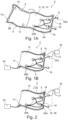
- connection elements 34 shows an end view from the outside of an end face of the test envelope 2 in the area of the connection elements 34.
- the lead-through elements 18 with the two half-shells can also be seen, which are guided around the connecting element 34 following the outer contour thereof.
- the plastic film 10 and the closure elements 8 can be seen, which are designed, for example, in the manner of strip-like clip closures.
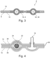
- the wall 2 is formed by an outer, in particular insulating layer, which is formed by a plastic film 10 and an inner conductive layer, which is in particular by a Tissue or braid 38 is formed.
- This consists, for example, of fine and finest metal wires or of metalized plastic or textile threads.
- the structure of the cable 20 with the inner conductor 22 and the insulation 24 (core sheath) can also be seen in this cross-sectional illustration.
- the measuring connection 16 is formed by a bolt-shaped element which contacts the braiding 38 on the inside and is routed to the outside.
- this is specifically a screw bolt, specifically with a flat head arranged on the inside, for example with a lens-shaped head.
- the screw is mechanically firmly connected to the wall 12 by means of a nut.
- the exemplary embodiment shows that the screw clamps two layers of the mesh 38 against one layer of the plastic film 10 . Alternatively, only one layer of the mesh 38 is braced.
- the measuring device 32 is electrically connected to this measuring connection 16 by means of a clamp, for example.
- the high flexibility of the wall 12 is essential for the method presented here, so that its conductive layer nestles against the cable harness 4 and its outer contour.
- the wall 12 has a comparatively small thickness D. This is preferably a maximum of 300 ⁇ m or less, depending on the configuration and structure of the wall 12.
- the thickness of the wall is defined by the entire structure of the wall 12, with a single-layer structure by the thickness D of one layer, eg the plastic film 10, and in a multi-layer construction by the total thickness of the multiple layers.
Landscapes
- Physics & Mathematics (AREA)
- General Physics & Mathematics (AREA)
- Testing Relating To Insulation (AREA)
Claims (14)
- Procédé pour vérifier l'isolation (24) d'un composant électrique, en particulier d'un faisceau de câbles haute tension (4), le composant électrique comportant une âme électrique qui est entourée de l'isolation (24) à vérifier, dans lequel- on fournit une enveloppe de vérification (2), dans laquelle le composant à vérifier est au moins en grande partie complètement inséré lors de la vérification,- l'enveloppe de vérification est configurée sous forme d'une poche de vérification qui comporte deux faces d'enveloppe se faisant face qui, au moins lors de l'excéution du processus de vérification, sont jointes l'une à l'autre sur les bords d'au moins trois côtés, la poche de vérification renfermant un espace de vérification et le composant électrique étant inséré dans la poche de vérification,- l'enveloppe de vérification (2) comporte une paroi (12) conductrice de l'électricité, en un matériau flexible, et pour ce qui est de la paroi (12) il s'agit d'une enveloppe de type film ou de type tissu,- l'enveloppe de vérification (2) s'applique, grâce à sa flexibilité, sur le contour externe de l'isolation (24),- on applique une tension de vérification sur l'âme électrique et on examine si l'isolation (24) est défectueuse.
- Procédé selon la revendication précédente, dans lequel on s'abstient d'introduire un milieu d'essai dans un espace intermédiaire entre l'enveloppe de vérification (2) servant d'électrode et l'isolation (24).
- Procédé selon l'une quelconque des revendications précédentes, dans lequel l'enveloppe de vérification (2) configurée en tant qu'une poche de vérification ne comporte qu'en un côté une ouverture en particulier pouvant être fermée, de préférence au moins une extrémité ou une borne (26A, 26B) du composant électrique étant passée en sortant à travers l'ouverture, et un élément de connexion (34) étant disposé sur l'ouverture.
- Procédé selon l'une quelconque des revendications précédentes, dans lequel une dépression est engendrée dans l'enveloppe de vérification (2), de sorte que l'enveloppe de vérification (2) s'accole à l'isolation (24) et vient en contact avec l'isolation (24) sur une grande partie, en particulier la totalité, de sa surface.
- Procédé selon l'une quelconque des revendications précédentes, dans lequel l'enveloppe de vérification (2) comporte un raccord d'aspiration (14) destiné à la production de la dépression.
- Procédé selon l'une quelconque des revendications précédentes, dans lequel l'enveloppe de vérification (2) peut être fermée de façon étanche à l'air lorsque le composant est inséré et à cette fin comporte de préférence au moins un élément de fermeture (8).
- Procédé selon l'une quelconque des revendications précédentes, dans lequel l'enveloppe de vérification (2) comporte un raccord de mesure (16) destiné au raccordement d'un appareil de mesure (32).
- Procédé selon l'une quelconque des revendications précédentes, dans lequel au moins une borne (26A, 26B) d'extrémité du composant est insérée dans l'enveloppe de vérification (2).
- Procédé selon l'une quelconque des revendications précédentes, dans lequel l'enveloppe de vérification (2) comporte un élément de raccordement (34) intégré, auquel le composant peut être raccordé à l'intérieur de l'enveloppe de vérification (2), l'élément de raccordement (34) étant passé, en particulier de manière étanche, à travers la paroi (12) de l'enveloppe de vérification (2).
- Procédé selon l'une quelconque des revendications précédentes, dans lequel la paroi (12) présente une épaisseur (D) dans la plage allant jusqu'à un maximum de 300 µm, de préférence un maximum de 200 µm ou un maximum de 100 µm.
- Procédé selon l'une quelconque des revendications précédentes, dans lequel la paroi (12) de l'enveloppe de vérification (2) est constituée d'un film de matière plastique (10) conducteur ou d'un film de matière plastique (10) muni d'un revêtement conducteur, et/ou
dans lequel la paroi (12 de l'enveloppe de vérification (2) comporte un film ainsi qu'une autre couche, conductrice, qui est constituée en particulier d'un tissu. - Procédé selon l'une quelconque des revendications précédentes, dans lequel la paroi (12) de l'enveloppe de vérification (2) est configurée à l'état initial sous forme d'une couche de film (6) et le composant à vérifier est déposé sur une partie (6A) de l'enveloppe de vérification (2) et ensuite une autre partie (6B) de l'enveloppe de vérification (6A) est placée sur le composant à vérifier.
- Procédé selon l'une quelconque des revendications précédentes, dans lequel après la vérification le composant reste dans l'enveloppe de vérification (2) et cette dernière est utilisée en tant qu'un emballage de transport.
- Dispositif destiné la vérification de l'isolation (24) d'un composant électrique, en particulier d'un faisceau de câbles haute tension (4), qui comporte une enveloppe de vérification (2), qui comporte deux faces d'enveloppe se faisant face qui, au moins lors de l'exécution du processus de vérification, sont jointes l'une à l'autre sur les bords d'au moins trois côtés pour la formation d'une poche de vérification, la poche de vérification renfermant un espace de vérification et le composant électrique à vérifier étant insérable dans la poche de vérification, et comporte une paroi (12) en un matériau conducteur de l'électricité, la paroi (12) consistant en une enveloppe de type film ou de type tissu, et l'enveloppe de vérification (2) étant fermée vis-à-vis de l'environnement, de façon étanche à l'air, par la paroi (12) et l'enveloppe de vérification (2) présentant une flexibilité, de sorte qu'elle peut s'appliquer, grâce à sa flexibilité, sur le contour externe de l'isolation (24), dans lequel l'enveloppe de vérification (2) présente de préférence une ou plusieurs des caractéristiques suivantes :- un raccord d'aspiration (14) destiné à la production d'une dépression à l'intérieur de l'enveloppe de vérification (2),- un élément de raccordement (34) intégré, destiné au raccordement d'une borne (26A) du composant à vérifier à l'intérieur de l'enveloppe de vérification (2),- au moins un élément de fermeture (8) destiné à la fermeture de manière étanche à l'air de l'enveloppe de vérification (2) ainsi que- un raccord de mesure (16) destiné au raccordement d'un appareil de mesure (32).
Applications Claiming Priority (2)
| Application Number | Priority Date | Filing Date | Title |
|---|---|---|---|
| DE102019210866.0A DE102019210866B4 (de) | 2019-07-23 | 2019-07-23 | Verfahren sowie Vorrichtung zur Prüfung der Isolation eines elektrischen Bauteils, insbesondere eines HV-Kabelsatzes |
| PCT/EP2020/067066 WO2021013446A1 (fr) | 2019-07-23 | 2020-06-19 | Procédé ainsi que dispositif pour vérifier l'isolation d'un composant électrique, en particulier d'un faisceau de câbles haute tension |
Publications (2)
| Publication Number | Publication Date |
|---|---|
| EP4004569A1 EP4004569A1 (fr) | 2022-06-01 |
| EP4004569B1 true EP4004569B1 (fr) | 2023-08-02 |
Family
ID=71130957
Family Applications (1)
| Application Number | Title | Priority Date | Filing Date |
|---|---|---|---|
| EP20734345.0A Active EP4004569B1 (fr) | 2019-07-23 | 2020-06-19 | Procédé ainsi que dispositif pour vérifier l'isolation d'un composant électrique, en particulier d'un faisceau de câbles haute tension |
Country Status (3)
| Country | Link |
|---|---|
| EP (1) | EP4004569B1 (fr) |
| DE (1) | DE102019210866B4 (fr) |
| WO (1) | WO2021013446A1 (fr) |
Cited By (1)
| Publication number | Priority date | Publication date | Assignee | Title |
|---|---|---|---|---|
| US20250164579A1 (en) * | 2023-11-17 | 2025-05-22 | Kries Energietechnik Gmbh & Co. Kg | Device For Detecting Faults In High-Voltage Transmission Lines |
Families Citing this family (4)
| Publication number | Priority date | Publication date | Assignee | Title |
|---|---|---|---|---|
| US11573258B1 (en) * | 2021-08-16 | 2023-02-07 | Aptiv Technologies Limited | Apparatus and method for testing insulated high voltage devices |
| CN114705955B (zh) * | 2022-03-02 | 2023-04-25 | 中国电子科技集团公司第二十九研究所 | 一种聚四氟乙烯高压导线绝缘耐压测试装置及方法 |
| DE102023203537B4 (de) | 2023-04-18 | 2025-03-20 | Leoni Bordnetz-Systeme Gmbh | Verfahren sowie Anlage zur Überprüfung der Spannungsfestigkeit einer Isolierung eines elektrischen Kabelsatzes |
| CN120686148A (zh) * | 2025-06-24 | 2025-09-23 | 浙江云一自动化科技有限公司 | 一种电缆线测试装置及其使用方法 |
Citations (1)
| Publication number | Priority date | Publication date | Assignee | Title |
|---|---|---|---|---|
| US20010052778A1 (en) * | 2000-06-07 | 2001-12-20 | Smith Paul Samuel | Device for detecting and locating insulation defects |
Family Cites Families (10)
| Publication number | Priority date | Publication date | Assignee | Title |
|---|---|---|---|---|
| FR2378286A1 (fr) | 1977-01-21 | 1978-08-18 | Cefilac | Testeur de rigidite dielectrique a sec pour cable electrique isole |
| DE3309658A1 (de) | 1983-03-17 | 1984-09-27 | Siemens AG, 1000 Berlin und 8000 München | Vorrichtung zur optischen pruefung der durchschlagsfestigkeit einer elektrischen isolation |
| JPS63273073A (ja) * | 1987-04-30 | 1988-11-10 | Oki Electric Ind Co Ltd | ケ−ブル絶縁試験方法 |
| KR100328186B1 (ko) * | 1999-12-15 | 2002-03-16 | 권문구 | 프리몰드 고무 슬리브 pd 시험치구 |
| DE10024809B4 (de) | 2000-05-16 | 2006-03-16 | Wee Electrotest Engineering Gmbh | Verfahren und Einrichtung zur Detektion von Schäden in der Isolation von elektrischen Leitungen und Kabelbäumen |
| US6518772B1 (en) * | 2000-05-16 | 2003-02-11 | Wee-Electrotest Engineering Gmbh | Method and device for the detection of damage in the insulation of electrical components, particularly of lines and cable harnesses |
| DE102012214231A1 (de) * | 2012-08-10 | 2014-02-13 | Robert Bosch Gmbh | Verfahren und Vorrichtung zum Kontrollieren von Isolationseigenschaften eines Gehäuses für Batteriezellen |
| DE102012214738A1 (de) * | 2012-08-20 | 2014-02-20 | Robert Bosch Gmbh | Prüfvorrichtung und Verfahren zur Prüfung der elektrischen Isolation der Oberfläche von elektrischen Bauteilen |
| DE102016116695B4 (de) | 2016-09-07 | 2024-06-20 | Leoni Bordnetz-Systeme Gmbh | Verfahren und Messvorrichtung zum Überprüfen eines Kabelbaumes |
| DE102017213922A1 (de) * | 2017-08-10 | 2019-02-14 | Robert Bosch Gmbh | Vorrichtung zur Prüfung der elektrischen Isolation einer Statorspule für eine elektrische Maschine |
-
2019
- 2019-07-23 DE DE102019210866.0A patent/DE102019210866B4/de active Active
-
2020
- 2020-06-19 WO PCT/EP2020/067066 patent/WO2021013446A1/fr not_active Ceased
- 2020-06-19 EP EP20734345.0A patent/EP4004569B1/fr active Active
Patent Citations (1)
| Publication number | Priority date | Publication date | Assignee | Title |
|---|---|---|---|---|
| US20010052778A1 (en) * | 2000-06-07 | 2001-12-20 | Smith Paul Samuel | Device for detecting and locating insulation defects |
Cited By (1)
| Publication number | Priority date | Publication date | Assignee | Title |
|---|---|---|---|---|
| US20250164579A1 (en) * | 2023-11-17 | 2025-05-22 | Kries Energietechnik Gmbh & Co. Kg | Device For Detecting Faults In High-Voltage Transmission Lines |
Also Published As
| Publication number | Publication date |
|---|---|
| WO2021013446A1 (fr) | 2021-01-28 |
| DE102019210866A1 (de) | 2021-01-28 |
| EP4004569A1 (fr) | 2022-06-01 |
| DE102019210866B4 (de) | 2024-03-21 |
Similar Documents
| Publication | Publication Date | Title |
|---|---|---|
| EP4004569B1 (fr) | Procédé ainsi que dispositif pour vérifier l'isolation d'un composant électrique, en particulier d'un faisceau de câbles haute tension | |
| DE69012719T2 (de) | Öffnung für den Zugang zu einem trennbaren elektrischen Verbinder und Zubehör für denselben. | |
| DE102016117261B3 (de) | System aus einem Steckverbinder, einem fluidgekühlten Kabel und einer Anschlusseinheit | |
| EP4005033B1 (fr) | Connecteur mâle avec surveillance d'isolation | |
| EP3495796B1 (fr) | Dispositif et procédé de vérification d'un adaptateur de charge pour fournir de l'énergie électrique à un stockage d'énergie d'un véhicule | |
| EP3891851A1 (fr) | Élément de raccordement pour la connexion électrique d'une ligne unique refroidie par fluide, unité de ligne unique refroidie par fluide, et câble de charge | |
| EP2091121B1 (fr) | Dispositif pour relier entre eux deux câbles électriques de haute tension ayant des diamètres différents | |
| EP2182602A1 (fr) | Dispositif destiné à une position de connexion entre deux câbles électriques haute tension | |
| DE102004046134A1 (de) | Freiluftendverschluss | |
| DE102023203537B4 (de) | Verfahren sowie Anlage zur Überprüfung der Spannungsfestigkeit einer Isolierung eines elektrischen Kabelsatzes | |
| EP1295136A1 (fr) | Detection de deteriorations dans l'isolation de composants electriques | |
| DE19726419A1 (de) | Heizleiter-Verbindungssystem in einem Flugzeug | |
| WO2019145139A1 (fr) | Traversée à haute tension enfichable et appareil électrique comprenant la traversée à haute tension enfichable | |
| DE2726403A1 (de) | Kabelgarnitur zum anschluss eines geschirmten starkstromkabels an ein elektrisches geraet | |
| EP0017953B1 (fr) | Garniture pour l'extrémité d'un câble moyenne tension ou haute tension | |
| AT517416B1 (de) | Kabel und verfahren zur herstellung eines kabels | |
| DE4403571C1 (de) | Verbindungsmuffe für kunststoffisolierte Hochspannungsenergieversorgungskabel | |
| DE102023108525A1 (de) | Prüfadapter für einen hochvoltkabelstrang, prüfsystem für einen hochvoltkabelstrang, sowie verfahren zur herstellung eines prüfadapters für einen hochvoltkabelstrang | |
| DE3542054C2 (de) | Endverschluß für insbesondere kunststoffisolierte Hochspannungskabel | |
| DE10024809B4 (de) | Verfahren und Einrichtung zur Detektion von Schäden in der Isolation von elektrischen Leitungen und Kabelbäumen | |
| DE3437481C2 (fr) | ||
| DE9404392U1 (de) | Überspannungsableiter-Kabelsteckteil-Verbindung | |
| DE102019105383A1 (de) | Messadapter für ein Elektrofahrzeug | |
| DE10026088C1 (de) | Muffenisolierkörper mit Schraubverbinder zur Herstellung einer Kabelverbindung für Mittelspannungs-Kunststoffkabel | |
| DE102011050330A1 (de) | Kraftfahrzeugbatterie |
Legal Events
| Date | Code | Title | Description |
|---|---|---|---|
| STAA | Information on the status of an ep patent application or granted ep patent |
Free format text: STATUS: UNKNOWN |
|
| STAA | Information on the status of an ep patent application or granted ep patent |
Free format text: STATUS: THE INTERNATIONAL PUBLICATION HAS BEEN MADE |
|
| PUAI | Public reference made under article 153(3) epc to a published international application that has entered the european phase |
Free format text: ORIGINAL CODE: 0009012 |
|
| STAA | Information on the status of an ep patent application or granted ep patent |
Free format text: STATUS: REQUEST FOR EXAMINATION WAS MADE |
|
| 17P | Request for examination filed |
Effective date: 20220222 |
|
| AK | Designated contracting states |
Kind code of ref document: A1 Designated state(s): AL AT BE BG CH CY CZ DE DK EE ES FI FR GB GR HR HU IE IS IT LI LT LU LV MC MK MT NL NO PL PT RO RS SE SI SK SM TR |
|
| STAA | Information on the status of an ep patent application or granted ep patent |
Free format text: STATUS: EXAMINATION IS IN PROGRESS |
|
| 17Q | First examination report despatched |
Effective date: 20220812 |
|
| DAV | Request for validation of the european patent (deleted) | ||
| DAX | Request for extension of the european patent (deleted) | ||
| GRAP | Despatch of communication of intention to grant a patent |
Free format text: ORIGINAL CODE: EPIDOSNIGR1 |
|
| STAA | Information on the status of an ep patent application or granted ep patent |
Free format text: STATUS: GRANT OF PATENT IS INTENDED |
|
| INTG | Intention to grant announced |
Effective date: 20230215 |
|
| GRAS | Grant fee paid |
Free format text: ORIGINAL CODE: EPIDOSNIGR3 |
|
| GRAA | (expected) grant |
Free format text: ORIGINAL CODE: 0009210 |
|
| STAA | Information on the status of an ep patent application or granted ep patent |
Free format text: STATUS: THE PATENT HAS BEEN GRANTED |
|
| P01 | Opt-out of the competence of the unified patent court (upc) registered |
Effective date: 20230527 |
|
| AK | Designated contracting states |
Kind code of ref document: B1 Designated state(s): AL AT BE BG CH CY CZ DE DK EE ES FI FR GB GR HR HU IE IS IT LI LT LU LV MC MK MT NL NO PL PT RO RS SE SI SK SM TR |
|
| REG | Reference to a national code |
Ref country code: GB Ref legal event code: FG4D Free format text: NOT ENGLISH |
|
| REG | Reference to a national code |
Ref country code: CH Ref legal event code: EP |
|
| REG | Reference to a national code |
Ref country code: DE Ref legal event code: R096 Ref document number: 502020004516 Country of ref document: DE |
|
| REG | Reference to a national code |
Ref country code: IE Ref legal event code: FG4D Free format text: LANGUAGE OF EP DOCUMENT: GERMAN |
|
| REG | Reference to a national code |
Ref country code: LT Ref legal event code: MG9D |
|
| REG | Reference to a national code |
Ref country code: NL Ref legal event code: MP Effective date: 20230802 |
|
| PG25 | Lapsed in a contracting state [announced via postgrant information from national office to epo] |
Ref country code: GR Free format text: LAPSE BECAUSE OF FAILURE TO SUBMIT A TRANSLATION OF THE DESCRIPTION OR TO PAY THE FEE WITHIN THE PRESCRIBED TIME-LIMIT Effective date: 20231103 |
|
| PG25 | Lapsed in a contracting state [announced via postgrant information from national office to epo] |
Ref country code: IS Free format text: LAPSE BECAUSE OF FAILURE TO SUBMIT A TRANSLATION OF THE DESCRIPTION OR TO PAY THE FEE WITHIN THE PRESCRIBED TIME-LIMIT Effective date: 20231202 |
|
| PG25 | Lapsed in a contracting state [announced via postgrant information from national office to epo] |
Ref country code: SE Free format text: LAPSE BECAUSE OF FAILURE TO SUBMIT A TRANSLATION OF THE DESCRIPTION OR TO PAY THE FEE WITHIN THE PRESCRIBED TIME-LIMIT Effective date: 20230802 Ref country code: RS Free format text: LAPSE BECAUSE OF FAILURE TO SUBMIT A TRANSLATION OF THE DESCRIPTION OR TO PAY THE FEE WITHIN THE PRESCRIBED TIME-LIMIT Effective date: 20230802 Ref country code: PT Free format text: LAPSE BECAUSE OF FAILURE TO SUBMIT A TRANSLATION OF THE DESCRIPTION OR TO PAY THE FEE WITHIN THE PRESCRIBED TIME-LIMIT Effective date: 20231204 Ref country code: NO Free format text: LAPSE BECAUSE OF FAILURE TO SUBMIT A TRANSLATION OF THE DESCRIPTION OR TO PAY THE FEE WITHIN THE PRESCRIBED TIME-LIMIT Effective date: 20231102 Ref country code: NL Free format text: LAPSE BECAUSE OF FAILURE TO SUBMIT A TRANSLATION OF THE DESCRIPTION OR TO PAY THE FEE WITHIN THE PRESCRIBED TIME-LIMIT Effective date: 20230802 Ref country code: LV Free format text: LAPSE BECAUSE OF FAILURE TO SUBMIT A TRANSLATION OF THE DESCRIPTION OR TO PAY THE FEE WITHIN THE PRESCRIBED TIME-LIMIT Effective date: 20230802 Ref country code: LT Free format text: LAPSE BECAUSE OF FAILURE TO SUBMIT A TRANSLATION OF THE DESCRIPTION OR TO PAY THE FEE WITHIN THE PRESCRIBED TIME-LIMIT Effective date: 20230802 Ref country code: IS Free format text: LAPSE BECAUSE OF FAILURE TO SUBMIT A TRANSLATION OF THE DESCRIPTION OR TO PAY THE FEE WITHIN THE PRESCRIBED TIME-LIMIT Effective date: 20231202 Ref country code: HR Free format text: LAPSE BECAUSE OF FAILURE TO SUBMIT A TRANSLATION OF THE DESCRIPTION OR TO PAY THE FEE WITHIN THE PRESCRIBED TIME-LIMIT Effective date: 20230802 Ref country code: GR Free format text: LAPSE BECAUSE OF FAILURE TO SUBMIT A TRANSLATION OF THE DESCRIPTION OR TO PAY THE FEE WITHIN THE PRESCRIBED TIME-LIMIT Effective date: 20231103 Ref country code: FI Free format text: LAPSE BECAUSE OF FAILURE TO SUBMIT A TRANSLATION OF THE DESCRIPTION OR TO PAY THE FEE WITHIN THE PRESCRIBED TIME-LIMIT Effective date: 20230802 |
|
| PG25 | Lapsed in a contracting state [announced via postgrant information from national office to epo] |
Ref country code: PL Free format text: LAPSE BECAUSE OF FAILURE TO SUBMIT A TRANSLATION OF THE DESCRIPTION OR TO PAY THE FEE WITHIN THE PRESCRIBED TIME-LIMIT Effective date: 20230802 |
|
| PG25 | Lapsed in a contracting state [announced via postgrant information from national office to epo] |
Ref country code: ES Free format text: LAPSE BECAUSE OF FAILURE TO SUBMIT A TRANSLATION OF THE DESCRIPTION OR TO PAY THE FEE WITHIN THE PRESCRIBED TIME-LIMIT Effective date: 20230802 |
|
| PG25 | Lapsed in a contracting state [announced via postgrant information from national office to epo] |
Ref country code: SM Free format text: LAPSE BECAUSE OF FAILURE TO SUBMIT A TRANSLATION OF THE DESCRIPTION OR TO PAY THE FEE WITHIN THE PRESCRIBED TIME-LIMIT Effective date: 20230802 Ref country code: RO Free format text: LAPSE BECAUSE OF FAILURE TO SUBMIT A TRANSLATION OF THE DESCRIPTION OR TO PAY THE FEE WITHIN THE PRESCRIBED TIME-LIMIT Effective date: 20230802 Ref country code: ES Free format text: LAPSE BECAUSE OF FAILURE TO SUBMIT A TRANSLATION OF THE DESCRIPTION OR TO PAY THE FEE WITHIN THE PRESCRIBED TIME-LIMIT Effective date: 20230802 Ref country code: EE Free format text: LAPSE BECAUSE OF FAILURE TO SUBMIT A TRANSLATION OF THE DESCRIPTION OR TO PAY THE FEE WITHIN THE PRESCRIBED TIME-LIMIT Effective date: 20230802 Ref country code: DK Free format text: LAPSE BECAUSE OF FAILURE TO SUBMIT A TRANSLATION OF THE DESCRIPTION OR TO PAY THE FEE WITHIN THE PRESCRIBED TIME-LIMIT Effective date: 20230802 Ref country code: CZ Free format text: LAPSE BECAUSE OF FAILURE TO SUBMIT A TRANSLATION OF THE DESCRIPTION OR TO PAY THE FEE WITHIN THE PRESCRIBED TIME-LIMIT Effective date: 20230802 Ref country code: SK Free format text: LAPSE BECAUSE OF FAILURE TO SUBMIT A TRANSLATION OF THE DESCRIPTION OR TO PAY THE FEE WITHIN THE PRESCRIBED TIME-LIMIT Effective date: 20230802 |
|
| REG | Reference to a national code |
Ref country code: DE Ref legal event code: R097 Ref document number: 502020004516 Country of ref document: DE |
|
| PG25 | Lapsed in a contracting state [announced via postgrant information from national office to epo] |
Ref country code: IT Free format text: LAPSE BECAUSE OF FAILURE TO SUBMIT A TRANSLATION OF THE DESCRIPTION OR TO PAY THE FEE WITHIN THE PRESCRIBED TIME-LIMIT Effective date: 20230802 |
|
| PLBE | No opposition filed within time limit |
Free format text: ORIGINAL CODE: 0009261 |
|
| STAA | Information on the status of an ep patent application or granted ep patent |
Free format text: STATUS: NO OPPOSITION FILED WITHIN TIME LIMIT |
|
| 26N | No opposition filed |
Effective date: 20240503 |
|
| PG25 | Lapsed in a contracting state [announced via postgrant information from national office to epo] |
Ref country code: SI Free format text: LAPSE BECAUSE OF FAILURE TO SUBMIT A TRANSLATION OF THE DESCRIPTION OR TO PAY THE FEE WITHIN THE PRESCRIBED TIME-LIMIT Effective date: 20230802 |
|
| PG25 | Lapsed in a contracting state [announced via postgrant information from national office to epo] |
Ref country code: BG Free format text: LAPSE BECAUSE OF FAILURE TO SUBMIT A TRANSLATION OF THE DESCRIPTION OR TO PAY THE FEE WITHIN THE PRESCRIBED TIME-LIMIT Effective date: 20230802 |
|
| PG25 | Lapsed in a contracting state [announced via postgrant information from national office to epo] |
Ref country code: BG Free format text: LAPSE BECAUSE OF FAILURE TO SUBMIT A TRANSLATION OF THE DESCRIPTION OR TO PAY THE FEE WITHIN THE PRESCRIBED TIME-LIMIT Effective date: 20230802 |
|
| PG25 | Lapsed in a contracting state [announced via postgrant information from national office to epo] |
Ref country code: MC Free format text: LAPSE BECAUSE OF FAILURE TO SUBMIT A TRANSLATION OF THE DESCRIPTION OR TO PAY THE FEE WITHIN THE PRESCRIBED TIME-LIMIT Effective date: 20230802 |
|
| REG | Reference to a national code |
Ref country code: CH Ref legal event code: PL |
|
| PG25 | Lapsed in a contracting state [announced via postgrant information from national office to epo] |
Ref country code: LU Free format text: LAPSE BECAUSE OF NON-PAYMENT OF DUE FEES Effective date: 20240619 |
|
| PG25 | Lapsed in a contracting state [announced via postgrant information from national office to epo] |
Ref country code: IE Free format text: LAPSE BECAUSE OF NON-PAYMENT OF DUE FEES Effective date: 20240619 |
|
| PG25 | Lapsed in a contracting state [announced via postgrant information from national office to epo] |
Ref country code: CH Free format text: LAPSE BECAUSE OF NON-PAYMENT OF DUE FEES Effective date: 20240630 Ref country code: BE Free format text: LAPSE BECAUSE OF NON-PAYMENT OF DUE FEES Effective date: 20240630 |
|
| REG | Reference to a national code |
Ref country code: BE Ref legal event code: MM Effective date: 20240630 |
|
| PGFP | Annual fee paid to national office [announced via postgrant information from national office to epo] |
Ref country code: DE Payment date: 20250618 Year of fee payment: 6 |
|
| PGFP | Annual fee paid to national office [announced via postgrant information from national office to epo] |
Ref country code: GB Payment date: 20250620 Year of fee payment: 6 |
|
| PGFP | Annual fee paid to national office [announced via postgrant information from national office to epo] |
Ref country code: FR Payment date: 20250626 Year of fee payment: 6 |
|
| PGFP | Annual fee paid to national office [announced via postgrant information from national office to epo] |
Ref country code: AT Payment date: 20250721 Year of fee payment: 5 |
|
| PG25 | Lapsed in a contracting state [announced via postgrant information from national office to epo] |
Ref country code: CY Free format text: LAPSE BECAUSE OF FAILURE TO SUBMIT A TRANSLATION OF THE DESCRIPTION OR TO PAY THE FEE WITHIN THE PRESCRIBED TIME-LIMIT; INVALID AB INITIO Effective date: 20200619 |
|
| PG25 | Lapsed in a contracting state [announced via postgrant information from national office to epo] |
Ref country code: HU Free format text: LAPSE BECAUSE OF FAILURE TO SUBMIT A TRANSLATION OF THE DESCRIPTION OR TO PAY THE FEE WITHIN THE PRESCRIBED TIME-LIMIT; INVALID AB INITIO Effective date: 20200619 |