EP4005939B1 - Deckelkörper - Google Patents
Deckelkörper Download PDFInfo
- Publication number
- EP4005939B1 EP4005939B1 EP20846187.1A EP20846187A EP4005939B1 EP 4005939 B1 EP4005939 B1 EP 4005939B1 EP 20846187 A EP20846187 A EP 20846187A EP 4005939 B1 EP4005939 B1 EP 4005939B1
- Authority
- EP
- European Patent Office
- Prior art keywords
- inlet
- lid
- formation part
- outlet formation
- container
- Prior art date
- Legal status (The legal status is an assumption and is not a legal conclusion. Google has not performed a legal analysis and makes no representation as to the accuracy of the status listed.)
- Active
Links
Images







Classifications
-
- B—PERFORMING OPERATIONS; TRANSPORTING
- B65—CONVEYING; PACKING; STORING; HANDLING THIN OR FILAMENTARY MATERIAL
- B65D—CONTAINERS FOR STORAGE OR TRANSPORT OF ARTICLES OR MATERIALS, e.g. BAGS, BARRELS, BOTTLES, BOXES, CANS, CARTONS, CRATES, DRUMS, JARS, TANKS, HOPPERS, FORWARDING CONTAINERS; ACCESSORIES, CLOSURES, OR FITTINGS THEREFOR; PACKAGING ELEMENTS; PACKAGES
- B65D47/00—Closures with filling and discharging, or with discharging, devices
- B65D47/36—Closures with frangible parts adapted to be pierced, torn or removed, to provide discharge openings
-
- B—PERFORMING OPERATIONS; TRANSPORTING
- B65—CONVEYING; PACKING; STORING; HANDLING THIN OR FILAMENTARY MATERIAL
- B65D—CONTAINERS FOR STORAGE OR TRANSPORT OF ARTICLES OR MATERIALS, e.g. BAGS, BARRELS, BOTTLES, BOXES, CANS, CARTONS, CRATES, DRUMS, JARS, TANKS, HOPPERS, FORWARDING CONTAINERS; ACCESSORIES, CLOSURES, OR FITTINGS THEREFOR; PACKAGING ELEMENTS; PACKAGES
- B65D43/00—Lids or covers for rigid or semi-rigid containers
- B65D43/02—Removable lids or covers
-
- B—PERFORMING OPERATIONS; TRANSPORTING
- B65—CONVEYING; PACKING; STORING; HANDLING THIN OR FILAMENTARY MATERIAL
- B65D—CONTAINERS FOR STORAGE OR TRANSPORT OF ARTICLES OR MATERIALS, e.g. BAGS, BARRELS, BOTTLES, BOXES, CANS, CARTONS, CRATES, DRUMS, JARS, TANKS, HOPPERS, FORWARDING CONTAINERS; ACCESSORIES, CLOSURES, OR FITTINGS THEREFOR; PACKAGING ELEMENTS; PACKAGES
- B65D3/00—Rigid or semi-rigid containers having bodies or peripheral walls of curved or partially-curved cross-section made by winding or bending paper without folding along defined lines
- B65D3/26—Opening arrangements or devices incorporated in, or attached to, containers
- B65D3/268—Opening arrangements or devices incorporated in, or attached to, containers the opening arrangement being located in a container closure
-
- B—PERFORMING OPERATIONS; TRANSPORTING
- B65—CONVEYING; PACKING; STORING; HANDLING THIN OR FILAMENTARY MATERIAL
- B65D—CONTAINERS FOR STORAGE OR TRANSPORT OF ARTICLES OR MATERIALS, e.g. BAGS, BARRELS, BOTTLES, BOXES, CANS, CARTONS, CRATES, DRUMS, JARS, TANKS, HOPPERS, FORWARDING CONTAINERS; ACCESSORIES, CLOSURES, OR FITTINGS THEREFOR; PACKAGING ELEMENTS; PACKAGES
- B65D43/00—Lids or covers for rigid or semi-rigid containers
- B65D43/02—Removable lids or covers
- B65D43/0202—Removable lids or covers without integral tamper element
- B65D43/0204—Removable lids or covers without integral tamper element secured by snapping over beads or projections
-
- B—PERFORMING OPERATIONS; TRANSPORTING
- B65—CONVEYING; PACKING; STORING; HANDLING THIN OR FILAMENTARY MATERIAL
- B65D—CONTAINERS FOR STORAGE OR TRANSPORT OF ARTICLES OR MATERIALS, e.g. BAGS, BARRELS, BOTTLES, BOXES, CANS, CARTONS, CRATES, DRUMS, JARS, TANKS, HOPPERS, FORWARDING CONTAINERS; ACCESSORIES, CLOSURES, OR FITTINGS THEREFOR; PACKAGING ELEMENTS; PACKAGES
- B65D43/00—Lids or covers for rigid or semi-rigid containers
- B65D43/14—Non-removable lids or covers
-
- B—PERFORMING OPERATIONS; TRANSPORTING
- B65—CONVEYING; PACKING; STORING; HANDLING THIN OR FILAMENTARY MATERIAL
- B65D—CONTAINERS FOR STORAGE OR TRANSPORT OF ARTICLES OR MATERIALS, e.g. BAGS, BARRELS, BOTTLES, BOXES, CANS, CARTONS, CRATES, DRUMS, JARS, TANKS, HOPPERS, FORWARDING CONTAINERS; ACCESSORIES, CLOSURES, OR FITTINGS THEREFOR; PACKAGING ELEMENTS; PACKAGES
- B65D47/00—Closures with filling and discharging, or with discharging, devices
- B65D47/04—Closures with discharging devices other than pumps
- B65D47/06—Closures with discharging devices other than pumps with pouring spouts or tubes; with discharge nozzles or passages
- B65D47/12—Closures with discharging devices other than pumps with pouring spouts or tubes; with discharge nozzles or passages having removable closures
-
- B—PERFORMING OPERATIONS; TRANSPORTING
- B65—CONVEYING; PACKING; STORING; HANDLING THIN OR FILAMENTARY MATERIAL
- B65D—CONTAINERS FOR STORAGE OR TRANSPORT OF ARTICLES OR MATERIALS, e.g. BAGS, BARRELS, BOTTLES, BOXES, CANS, CARTONS, CRATES, DRUMS, JARS, TANKS, HOPPERS, FORWARDING CONTAINERS; ACCESSORIES, CLOSURES, OR FITTINGS THEREFOR; PACKAGING ELEMENTS; PACKAGES
- B65D51/00—Closures not otherwise provided for
- B65D51/24—Closures not otherwise provided for combined or co-operating with auxiliary devices for non-closing purposes
-
- B—PERFORMING OPERATIONS; TRANSPORTING
- B65—CONVEYING; PACKING; STORING; HANDLING THIN OR FILAMENTARY MATERIAL
- B65D—CONTAINERS FOR STORAGE OR TRANSPORT OF ARTICLES OR MATERIALS, e.g. BAGS, BARRELS, BOTTLES, BOXES, CANS, CARTONS, CRATES, DRUMS, JARS, TANKS, HOPPERS, FORWARDING CONTAINERS; ACCESSORIES, CLOSURES, OR FITTINGS THEREFOR; PACKAGING ELEMENTS; PACKAGES
- B65D53/00—Sealing or packing elements; Sealings formed by liquid or plastics material
-
- B—PERFORMING OPERATIONS; TRANSPORTING
- B65—CONVEYING; PACKING; STORING; HANDLING THIN OR FILAMENTARY MATERIAL
- B65D—CONTAINERS FOR STORAGE OR TRANSPORT OF ARTICLES OR MATERIALS, e.g. BAGS, BARRELS, BOTTLES, BOXES, CANS, CARTONS, CRATES, DRUMS, JARS, TANKS, HOPPERS, FORWARDING CONTAINERS; ACCESSORIES, CLOSURES, OR FITTINGS THEREFOR; PACKAGING ELEMENTS; PACKAGES
- B65D2231/00—Means for facilitating the complete expelling of the contents
- B65D2231/02—Precut holes or weakened zones
- B65D2231/025—Precut holes or weakened zones for draining or discharging the liquid contents, e.g. soup, milk
-
- B—PERFORMING OPERATIONS; TRANSPORTING
- B65—CONVEYING; PACKING; STORING; HANDLING THIN OR FILAMENTARY MATERIAL
- B65D—CONTAINERS FOR STORAGE OR TRANSPORT OF ARTICLES OR MATERIALS, e.g. BAGS, BARRELS, BOTTLES, BOXES, CANS, CARTONS, CRATES, DRUMS, JARS, TANKS, HOPPERS, FORWARDING CONTAINERS; ACCESSORIES, CLOSURES, OR FITTINGS THEREFOR; PACKAGING ELEMENTS; PACKAGES
- B65D2517/00—Containers specially constructed to be opened by cutting, piercing or tearing of wall portions, e.g. preserving cans or tins
- B65D2517/0001—Details
- B65D2517/001—Action for opening container
- B65D2517/0013—Action for opening container pull-out tear panel, e.g. by means of a tear-tab
-
- B—PERFORMING OPERATIONS; TRANSPORTING
- B65—CONVEYING; PACKING; STORING; HANDLING THIN OR FILAMENTARY MATERIAL
- B65D—CONTAINERS FOR STORAGE OR TRANSPORT OF ARTICLES OR MATERIALS, e.g. BAGS, BARRELS, BOTTLES, BOXES, CANS, CARTONS, CRATES, DRUMS, JARS, TANKS, HOPPERS, FORWARDING CONTAINERS; ACCESSORIES, CLOSURES, OR FITTINGS THEREFOR; PACKAGING ELEMENTS; PACKAGES
- B65D2517/00—Containers specially constructed to be opened by cutting, piercing or tearing of wall portions, e.g. preserving cans or tins
- B65D2517/0001—Details
- B65D2517/0058—Other details of container end panel
- B65D2517/008—Materials of container end panel
- B65D2517/0085—Foil-like, e.g. paper or cardboard
-
- B—PERFORMING OPERATIONS; TRANSPORTING
- B65—CONVEYING; PACKING; STORING; HANDLING THIN OR FILAMENTARY MATERIAL
- B65D—CONTAINERS FOR STORAGE OR TRANSPORT OF ARTICLES OR MATERIALS, e.g. BAGS, BARRELS, BOTTLES, BOXES, CANS, CARTONS, CRATES, DRUMS, JARS, TANKS, HOPPERS, FORWARDING CONTAINERS; ACCESSORIES, CLOSURES, OR FITTINGS THEREFOR; PACKAGING ELEMENTS; PACKAGES
- B65D2517/00—Containers specially constructed to be opened by cutting, piercing or tearing of wall portions, e.g. preserving cans or tins
- B65D2517/0001—Details
- B65D2517/0058—Other details of container end panel
- B65D2517/008—Materials of container end panel
- B65D2517/0085—Foil-like, e.g. paper or cardboard
- B65D2517/0086—Foil-like, e.g. paper or cardboard laminated
-
- B—PERFORMING OPERATIONS; TRANSPORTING
- B65—CONVEYING; PACKING; STORING; HANDLING THIN OR FILAMENTARY MATERIAL
- B65D—CONTAINERS FOR STORAGE OR TRANSPORT OF ARTICLES OR MATERIALS, e.g. BAGS, BARRELS, BOTTLES, BOXES, CANS, CARTONS, CRATES, DRUMS, JARS, TANKS, HOPPERS, FORWARDING CONTAINERS; ACCESSORIES, CLOSURES, OR FITTINGS THEREFOR; PACKAGING ELEMENTS; PACKAGES
- B65D2517/00—Containers specially constructed to be opened by cutting, piercing or tearing of wall portions, e.g. preserving cans or tins
- B65D2517/50—Non-integral frangible members applied to, or inserted in, a preformed opening
- B65D2517/5072—Details of hand grip, tear- or lift-tab
- B65D2517/5083—Details of hand grip, tear- or lift-tab with means facilitating initial lifting of tape, e.g. lift or pull-tabs
- B65D2517/5089—Lift- or tear-tab formed as a separate piece from flexible tape of foil-like material
-
- B—PERFORMING OPERATIONS; TRANSPORTING
- B65—CONVEYING; PACKING; STORING; HANDLING THIN OR FILAMENTARY MATERIAL
- B65D—CONTAINERS FOR STORAGE OR TRANSPORT OF ARTICLES OR MATERIALS, e.g. BAGS, BARRELS, BOTTLES, BOXES, CANS, CARTONS, CRATES, DRUMS, JARS, TANKS, HOPPERS, FORWARDING CONTAINERS; ACCESSORIES, CLOSURES, OR FITTINGS THEREFOR; PACKAGING ELEMENTS; PACKAGES
- B65D2543/00—Lids or covers essentially for box-like containers
- B65D2543/00009—Details of lids or covers for rigid or semi-rigid containers
- B65D2543/00018—Overall construction of the lid
- B65D2543/00046—Drinking-through lids
-
- B—PERFORMING OPERATIONS; TRANSPORTING
- B65—CONVEYING; PACKING; STORING; HANDLING THIN OR FILAMENTARY MATERIAL
- B65D—CONTAINERS FOR STORAGE OR TRANSPORT OF ARTICLES OR MATERIALS, e.g. BAGS, BARRELS, BOTTLES, BOXES, CANS, CARTONS, CRATES, DRUMS, JARS, TANKS, HOPPERS, FORWARDING CONTAINERS; ACCESSORIES, CLOSURES, OR FITTINGS THEREFOR; PACKAGING ELEMENTS; PACKAGES
- B65D2543/00—Lids or covers essentially for box-like containers
- B65D2543/00009—Details of lids or covers for rigid or semi-rigid containers
- B65D2543/00018—Overall construction of the lid
- B65D2543/00064—Shape of the outer periphery
- B65D2543/00074—Shape of the outer periphery curved
- B65D2543/00092—Shape of the outer periphery curved circular
-
- B—PERFORMING OPERATIONS; TRANSPORTING
- B65—CONVEYING; PACKING; STORING; HANDLING THIN OR FILAMENTARY MATERIAL
- B65D—CONTAINERS FOR STORAGE OR TRANSPORT OF ARTICLES OR MATERIALS, e.g. BAGS, BARRELS, BOTTLES, BOXES, CANS, CARTONS, CRATES, DRUMS, JARS, TANKS, HOPPERS, FORWARDING CONTAINERS; ACCESSORIES, CLOSURES, OR FITTINGS THEREFOR; PACKAGING ELEMENTS; PACKAGES
- B65D2543/00—Lids or covers essentially for box-like containers
- B65D2543/00009—Details of lids or covers for rigid or semi-rigid containers
- B65D2543/00018—Overall construction of the lid
- B65D2543/00231—Overall construction of the lid made of several pieces
- B65D2543/0024—Overall construction of the lid made of several pieces two pieces, one forming at least the whole skirt, the other forming at least the whole upper part
-
- B—PERFORMING OPERATIONS; TRANSPORTING
- B65—CONVEYING; PACKING; STORING; HANDLING THIN OR FILAMENTARY MATERIAL
- B65D—CONTAINERS FOR STORAGE OR TRANSPORT OF ARTICLES OR MATERIALS, e.g. BAGS, BARRELS, BOTTLES, BOXES, CANS, CARTONS, CRATES, DRUMS, JARS, TANKS, HOPPERS, FORWARDING CONTAINERS; ACCESSORIES, CLOSURES, OR FITTINGS THEREFOR; PACKAGING ELEMENTS; PACKAGES
- B65D2543/00—Lids or covers essentially for box-like containers
- B65D2543/00009—Details of lids or covers for rigid or semi-rigid containers
- B65D2543/00018—Overall construction of the lid
- B65D2543/00259—Materials used
- B65D2543/00268—Paper
-
- B—PERFORMING OPERATIONS; TRANSPORTING
- B65—CONVEYING; PACKING; STORING; HANDLING THIN OR FILAMENTARY MATERIAL
- B65D—CONTAINERS FOR STORAGE OR TRANSPORT OF ARTICLES OR MATERIALS, e.g. BAGS, BARRELS, BOTTLES, BOXES, CANS, CARTONS, CRATES, DRUMS, JARS, TANKS, HOPPERS, FORWARDING CONTAINERS; ACCESSORIES, CLOSURES, OR FITTINGS THEREFOR; PACKAGING ELEMENTS; PACKAGES
- B65D2543/00—Lids or covers essentially for box-like containers
- B65D2543/00009—Details of lids or covers for rigid or semi-rigid containers
- B65D2543/00018—Overall construction of the lid
- B65D2543/00259—Materials used
- B65D2543/00314—Combination, e.g. laminates, several different materials
-
- B—PERFORMING OPERATIONS; TRANSPORTING
- B65—CONVEYING; PACKING; STORING; HANDLING THIN OR FILAMENTARY MATERIAL
- B65D—CONTAINERS FOR STORAGE OR TRANSPORT OF ARTICLES OR MATERIALS, e.g. BAGS, BARRELS, BOTTLES, BOXES, CANS, CARTONS, CRATES, DRUMS, JARS, TANKS, HOPPERS, FORWARDING CONTAINERS; ACCESSORIES, CLOSURES, OR FITTINGS THEREFOR; PACKAGING ELEMENTS; PACKAGES
- B65D2543/00—Lids or covers essentially for box-like containers
- B65D2543/00009—Details of lids or covers for rigid or semi-rigid containers
- B65D2543/00425—Lids or covers welded or adhered to the container
-
- B—PERFORMING OPERATIONS; TRANSPORTING
- B65—CONVEYING; PACKING; STORING; HANDLING THIN OR FILAMENTARY MATERIAL
- B65D—CONTAINERS FOR STORAGE OR TRANSPORT OF ARTICLES OR MATERIALS, e.g. BAGS, BARRELS, BOTTLES, BOXES, CANS, CARTONS, CRATES, DRUMS, JARS, TANKS, HOPPERS, FORWARDING CONTAINERS; ACCESSORIES, CLOSURES, OR FITTINGS THEREFOR; PACKAGING ELEMENTS; PACKAGES
- B65D2543/00—Lids or covers essentially for box-like containers
- B65D2543/00009—Details of lids or covers for rigid or semi-rigid containers
- B65D2543/00444—Contact between the container and the lid
- B65D2543/00481—Contact between the container and the lid on the inside or the outside of the container
- B65D2543/0049—Contact between the container and the lid on the inside or the outside of the container on the inside, or a part turned to the inside of the mouth of the container
- B65D2543/00527—NO contact
-
- B—PERFORMING OPERATIONS; TRANSPORTING
- B65—CONVEYING; PACKING; STORING; HANDLING THIN OR FILAMENTARY MATERIAL
- B65D—CONTAINERS FOR STORAGE OR TRANSPORT OF ARTICLES OR MATERIALS, e.g. BAGS, BARRELS, BOTTLES, BOXES, CANS, CARTONS, CRATES, DRUMS, JARS, TANKS, HOPPERS, FORWARDING CONTAINERS; ACCESSORIES, CLOSURES, OR FITTINGS THEREFOR; PACKAGING ELEMENTS; PACKAGES
- B65D2543/00—Lids or covers essentially for box-like containers
- B65D2543/00009—Details of lids or covers for rigid or semi-rigid containers
- B65D2543/00444—Contact between the container and the lid
- B65D2543/00481—Contact between the container and the lid on the inside or the outside of the container
- B65D2543/00537—Contact between the container and the lid on the inside or the outside of the container on the outside, or a part turned to the outside of the mouth of the container
-
- B—PERFORMING OPERATIONS; TRANSPORTING
- B65—CONVEYING; PACKING; STORING; HANDLING THIN OR FILAMENTARY MATERIAL
- B65D—CONTAINERS FOR STORAGE OR TRANSPORT OF ARTICLES OR MATERIALS, e.g. BAGS, BARRELS, BOTTLES, BOXES, CANS, CARTONS, CRATES, DRUMS, JARS, TANKS, HOPPERS, FORWARDING CONTAINERS; ACCESSORIES, CLOSURES, OR FITTINGS THEREFOR; PACKAGING ELEMENTS; PACKAGES
- B65D2543/00—Lids or covers essentially for box-like containers
- B65D2543/00009—Details of lids or covers for rigid or semi-rigid containers
- B65D2543/00444—Contact between the container and the lid
- B65D2543/00592—Snapping means
- B65D2543/00601—Snapping means on the container
- B65D2543/00611—Profiles
- B65D2543/00638—Rolled edge
-
- B—PERFORMING OPERATIONS; TRANSPORTING
- B65—CONVEYING; PACKING; STORING; HANDLING THIN OR FILAMENTARY MATERIAL
- B65D—CONTAINERS FOR STORAGE OR TRANSPORT OF ARTICLES OR MATERIALS, e.g. BAGS, BARRELS, BOTTLES, BOXES, CANS, CARTONS, CRATES, DRUMS, JARS, TANKS, HOPPERS, FORWARDING CONTAINERS; ACCESSORIES, CLOSURES, OR FITTINGS THEREFOR; PACKAGING ELEMENTS; PACKAGES
- B65D2543/00—Lids or covers essentially for box-like containers
- B65D2543/00009—Details of lids or covers for rigid or semi-rigid containers
- B65D2543/00444—Contact between the container and the lid
- B65D2543/00592—Snapping means
- B65D2543/00601—Snapping means on the container
- B65D2543/00675—Periphery concerned
- B65D2543/00685—Totality
-
- B—PERFORMING OPERATIONS; TRANSPORTING
- B65—CONVEYING; PACKING; STORING; HANDLING THIN OR FILAMENTARY MATERIAL
- B65D—CONTAINERS FOR STORAGE OR TRANSPORT OF ARTICLES OR MATERIALS, e.g. BAGS, BARRELS, BOTTLES, BOXES, CANS, CARTONS, CRATES, DRUMS, JARS, TANKS, HOPPERS, FORWARDING CONTAINERS; ACCESSORIES, CLOSURES, OR FITTINGS THEREFOR; PACKAGING ELEMENTS; PACKAGES
- B65D2543/00—Lids or covers essentially for box-like containers
- B65D2543/00009—Details of lids or covers for rigid or semi-rigid containers
- B65D2543/00444—Contact between the container and the lid
- B65D2543/00592—Snapping means
- B65D2543/00712—Snapping means on the lid
- B65D2543/00722—Profiles
- B65D2543/00759—Flange or lip
-
- B—PERFORMING OPERATIONS; TRANSPORTING
- B65—CONVEYING; PACKING; STORING; HANDLING THIN OR FILAMENTARY MATERIAL
- B65D—CONTAINERS FOR STORAGE OR TRANSPORT OF ARTICLES OR MATERIALS, e.g. BAGS, BARRELS, BOTTLES, BOXES, CANS, CARTONS, CRATES, DRUMS, JARS, TANKS, HOPPERS, FORWARDING CONTAINERS; ACCESSORIES, CLOSURES, OR FITTINGS THEREFOR; PACKAGING ELEMENTS; PACKAGES
- B65D2543/00—Lids or covers essentially for box-like containers
- B65D2543/00009—Details of lids or covers for rigid or semi-rigid containers
- B65D2543/00444—Contact between the container and the lid
- B65D2543/00592—Snapping means
- B65D2543/00712—Snapping means on the lid
- B65D2543/00787—Periphery concerned
- B65D2543/00796—Totality
-
- B—PERFORMING OPERATIONS; TRANSPORTING
- B65—CONVEYING; PACKING; STORING; HANDLING THIN OR FILAMENTARY MATERIAL
- B65D—CONTAINERS FOR STORAGE OR TRANSPORT OF ARTICLES OR MATERIALS, e.g. BAGS, BARRELS, BOTTLES, BOXES, CANS, CARTONS, CRATES, DRUMS, JARS, TANKS, HOPPERS, FORWARDING CONTAINERS; ACCESSORIES, CLOSURES, OR FITTINGS THEREFOR; PACKAGING ELEMENTS; PACKAGES
- B65D3/00—Rigid or semi-rigid containers having bodies or peripheral walls of curved or partially-curved cross-section made by winding or bending paper without folding along defined lines
- B65D3/02—Rigid or semi-rigid containers having bodies or peripheral walls of curved or partially-curved cross-section made by winding or bending paper without folding along defined lines characterised by shape
- B65D3/06—Rigid or semi-rigid containers having bodies or peripheral walls of curved or partially-curved cross-section made by winding or bending paper without folding along defined lines characterised by shape essentially conical or frusto-conical
Definitions
- the present invention relates to a lid that has been formed to be mountable on a container.
- a lid has been mounted on a container in order to close a mouth formed in the container and avoid leakage to the outside of various articles stored in the container that serve as the contents of the container.
- the lid is mounted on the container in an internally or externally fitted manner, and tightly seals an internal space inside the container.
- various aspects can be considered as the various articles stored in the container.
- Examples include powdery articles, granular articles, solid articles, and the like.
- Another example is liquid articles such as various beverages of food and beverage.
- liquid articles such as beverages easily leak out.
- a container be tightly sealed with a lid with more precision.
- a lid having higher sealability be used in order to prevent a beverage in a container from leaking out.
- a lid having the configuration described in Patent Literature 1 listed below has been disclosed.
- a plastic lid that has been formed to be mountable on a container mouth has been disclosed.
- WO89/00955 discloses a packing container having a tubular body and a cover closing the upper opening of the body.
- the cover has a flat wall and a U-shaped folded rim which defines the flat wall.
- the cover is produced from a multiple-layer composite material which has an outer layer of plastic or cardboard.
- the cover has a U-shaped start portion that can be bent for allowing a gas exchange and a strip fastened to the U-shaped portion.
- the strip has one end not adhered to the cover, which can be pulled up to bend the U-shaped portion out of the cover surface.
- WO2016/069766 discloses a paperboard cup lid including a sidewall and a top wall, the top wall including a tab which breaks perforations to create an opening on the top wall.
- Patent Literature 1 JP 2016-169023 A
- a plastic material is used, as described as a lid for beverages in Patent Literature 1 listed above, the lid is molded by using various molding machines in vacuum molding or the like, and therefore a thickness is likely to decrease. If a thickness of a lid decreases, as described above, in a case where the contents of a container is a beverage or the like that has a high temperature, the heat of the beverage that has flown out from an opening is easily transferred to the lid, and this causes a problem in which a user easily feels heat and is likely to feel uncomfortable. In particular, in the case of use as a lid for beverages, human lips are sensitive to temperature, and this causes a problem in which a user is more likely to feel uncomfortable.
- the gist of the present invention is as defined in claims 1-13.
- a lid that closes a mouth of a container is made of a material principally including a paper material.
- the lid includes: a side wall that is fitted to the mouth of the container; and a top lid that is surrounded by the side wall.
- the top lid includes: an inlet/outlet formation part that forms an inlet/outlet for an article stored in the container; and a temporary fixing part that temporarily fixes the inlet/outlet formation part to the top lid. This can make it difficult for an article stored in the container to leak out to the outside.
- the lid can be user-friendly for the purpose, and a manufacturing cost can be significantly reduced. Further, according to the present invention, a lid that is conscious of environmental issues can be provided.
- a lid according to the present invention is formed by using a material principally including a paper material.
- the paper material include what is called paper that has been manufactured by sticking, for example, vegetable fiber or other fiber, chemical fiber paper, synthetic paper, waterproof paper, coated paper, substitute paper, parchment, wool paper, glass fiber paper, stone paper, ceramic paper, and the like.
- the paper material is preferably a material including a cellulose component such as pulp, more preferably a material including 50% or more by weigh of the cellulose component, further more preferably a material including 60% or more by weigh of the cellulose component, further more preferably a material including 70% or more by weigh of the cellulose component, especially preferably a material including 80% or more by weigh of the cellulose component, and most preferably a material including 90% or more by weigh of the cellulose component.
- examples of pulp include wood pulp, non-wood pulp, synthetic pulp, and waste paper pulp. More specifically, one or several types can be appropriately selected and used from ground wood pulp (GP), stone ground pulp (SGP), refiner ground pulp (RGP), pressurized ground wood pulp (PGW), mechanical pulp (MP) such as thermomechanical pulp (TMP), chemithermomechanical pulp (CTMP), bleached chemithermomechanical pulp (BCTMP), or the like, chemimechanical pulp (CGP), semichemical pulp (SCP), kraft pulp (KP) such as leaf bleached kraft pulp (LBKP), needle bleached kraft pulp (NBKP), or the like, chemical pulp (CP) such as soda pulp (AP), sulfite pulp (SP), dissolving pulp (DP), or the like, synthetic pulp using, as a raw material, nylon, rayon, polyester, polyvinyl alcohol (PVA), or the like, tailings pulp (TP), rag pulp using, as a raw material, cotton, flax, hemp, jute, Manila
- a paper material including a resin coated layer at least on one side may be used as the paper material.
- a paper material including a coated layer it is preferable that the coated layer be located at least on an inner face side of a container.
- the coated layer can be formed by using the resin film or a coating agent.
- the film may be a monolayer film or a multilayer film, and the coated layer may be formed by superimposing and sticking monolayer or multilayer films.
- the coated layer may be formed not only by coating one type of coating agent but also by superimposing and coating two or more types of coating agents.
- a resin forming the coated layer for example, the following can be used: polystyrene, polyethylene, polypropylene, polyethylene terephthalate, polyurethane, polyvinyl chloride, polyvinylidene chloride, polyvinyl acetate, cyanoacrylate, epoxy resin, polyacrylic acid resin, polymethacrylic acid resin, nylon, polycarbonate; a naturally degradable resin such as polycaprolactone, polyhydroxyalkanoate, polyhydroxybutyrate, polylactic acid, a starch-based resin such as an esterified starch or the like, cellulose acetate, polyethylene succinate, polyvinyl alcohol, polyglycolic acid, chitosan/cellulose/starch, poly(hydroxybutyrate/hydroxyhexanoate), poly(caprolactone/butylene succinate), polybutylene succinate, poly(butylene succinate/adipate), poly(butylene succinate/carbonate), poly(ethylene terephthalate/succinate
- Naturally degradable resin examples include a natural resin, naturally degradable plastic, biomass plastic, and the like.
- naturally degradable plastic and biomass plastic include a naturally degradable resin such as polycaprolactone, polyhydroxyalkanoate, polyhydroxybutyrate, polylactic acid, a starch-based resin such as an esterified starch or the like, cellulose acetate, polyethylene succinate, polyvinyl alcohol, polyglycolic acid, chitosan/cellulose/starch, poly(hydroxybutyrate/hydroxyhexanoate), poly(caprolactone/butylene succinate), polybutylene succinate, poly(butylene succinate/adipate), poly(butylene succinate/carbonate), poly(ethylene terephthalate/succinate), poly(butylene adipate/terephthalate), poly(tetramethylene adipate/terephthalate), or the like, and a naturally degradable resin mixture.
- a naturally degradable resin such as polycaprolactone
- the naturally degradable resin may contain an additive listed in a positive list of Japan BioPlastics Association, for example, lubricant such as a stearic acid amide, a fatty acid ester, fatty acid metal salt, fatty acid, oil, a glyceryl fatty acid ester, or the like; stabilizer such as triphenyl phosphate, phthalic anhydride, tris dibutyl phosphate, acetic anhydride, or the like; an inorganic material such as titanium dioxide, kaolin, mica, bentonite, diatomaceous earth, magnesium oxide, silica sand aluminum, calcium carbonate, calcium hydroxide, seashell powder, or the like; surfactant such as a higher fatty acid amide, nonionic surfactant, a glycerol fatty acid ester, or the like; a foaming agent such as citric acid, sodium hydrogen carbonate, butane, or the like; another material such as an antistatic agent, a hotmelt
- a lid according to the present invention is not restricted by the contents of a container on which the lid is mounted, but can be applied to a lid that closes a container that can hold any type of contents.
- a first embodiment of a lid 1 according to the present invention is described in detail with reference to the drawings.
- the lid 1 according to the present invention is described by using, as an example, a lid 1 that is applied to a container (a cup) that holds various beverages, such as a coffee cup.
- the lid 1 according to the present invention is not limited to a lid 1 of a container that holds beverages, and can also be applied to a lid 1 of a container that stores food rather than beverages.
- the lid 1 according to the present invention can be applied as a lid 1 that is applied to a container that stores various articles other than food, for example, parts such as bolts or nuts, or articles other than the above.
- the lid 1 according to the present embodiment is described by using, as an example, a lid having a circular shape in a plan view.
- a shape of the lid 1 is not limited to a circular shape, and may be a polygonal shape or various shapes that can be arbitrarily set rather than the polygonal shape.
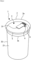
- the lid 1 includes a side wall 2 that is fitted to a mouth 22 (see Fig. 4 ) of a container 21, and a top lid 3 that is surrounded by the side wall 2.
- the top lid 3 includes an inlet/outlet formation part 4 of the contents that serve as an article stored in a container and are stored in an inside 23 (see Fig. 4 ) of the container 21 (in the present embodiment, description is provided by using beverages, but the contents may be an article other than beverages, for example, food or an article other than food and beverage).
- the inlet/outlet formation part 4 has been mounted with a sticker member 31.
- the side wall 2 has been formed to surround a peripheral edge 3c of the top lid 3. As illustrated in Fig. 1(a) , the side wall 2 has been formed in a taper shape in which a dimension decreases toward a lower end 2b from an upper end 2a. In addition, in the side wall 2, a projection part 5 has been formed at the upper end 2a. The projection part 5 has been formed to protrude outward from the side wall 2. Further, in the present embodiment, the projection part 5 has been formed by winding a paper material constituting the side wall 2 to be formed in a curled shape. However, the projection part 5 does not always need to be formed in a curled shape. For example, the projection part 5 may be formed by generating a curled shape and vertically crushing the curled shape.
- the projection part 5 may be formed by bending a paper material forming the side wall 2 to cause the paper material to extend outward from the upper end 2a.
- the upper end 2a may have a shape obtained by folding back the paper material forming the side wall 2.
- a shape other than the shapes described above may be used.
- the projection part 5 by forming the projection part 5, the entire strength of the side wall 2 cannot only be increased, but a user can also easily drink a beverage in the container 21. Note that in the present embodiment, description has been provided by using an example where the projection part 5 has been formed to protrude outward from the side wall 2, but the projection part 5 may be formed to protrude inward from the side wall 2.
- the lower end side 2b of the side wall 2 is joined to the peripheral wall 3b described below of the top lid 3.
- the lower end side 2b and the peripheral wall 3b can be joined by arbitrarily selecting a conventionally known joining method such as heat sealing, ultrasonic joining, thermal fusion, or joining using an adhesive. Note that this joining method is not limited to the methods described above, and a method other than these methods may be used.
- the peripheral wall 3b that has been formed in a periphery of the top lid 3 is sandwiched between the side wall 2 and a bent piece 2c formed by bending the lower end side 2b of the side wall 2 in an inward direction, and joining is performed.
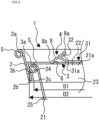
- the lid 1 according to the present embodiment has been formed in such a way that an inner dimension D1 at the lower end 2b of the side wall 2 is smaller than an outer dimension D2 at an upper end 21a of the container 21. Therefore, when the lid 1 is mounted on the container 21, the lid 1 is elastically transformed, and is fitted to the upper end 21a of the container 21.
- an outer face of a projection part 24 of the container 21 is in contact with an inner face of the peripheral wall 3b and a lower face of a top lid body 3a in the lid 1, as illustrated in Fig. 4 , and the lid 1 can be reliably mounted on the container 21.
- the lid 1 has a configuration in which two or three paper materials have been stacked. This can also make it difficult for the lid 1 to come off from the container 21.
- the bent piece 2c has been formed to be joined to the inside face of the peripheral wall 3b from a portion near a center in a height direction of the inner face of the peripheral wall 3b to the lower end 2b.
- the bent piece 2c may be formed in such a way that an upper end of the bent piece 2c is located in a position in close contact with an upper edge of the peripheral wall 3b and a lower end of the bent piece 2c is located in a position of the lower end 2b, or the bent piece 2c may be formed in another position. Note that if the upper end of the bent piece 2c is located near the center in the height direction of the inner face of the peripheral wall 3b, as illustrated in Fig. 4 , the upper end of the bent piece 2c is fitted to the projection part 24 of the container 21, and the container 21 can be reliably closed by using the lid 1.
- the side wall 2 has been formed in a circular shape, but an arbitrary shape other than the circular shape, such as an elliptical shape, may be used.
- a polygonal shape such as a rectangular shape or a hexagonal shape, may be used, or another shape may be used.
- a rising part 25 that forms a side wall of the container 21 has been formed to have the same taper angle as a taper angle of the side wall 2 of the lid 1, and stated another way, the rising part 25 has been formed to be parallel to the side wall 2, but this is not restrictive.
- the rising part 25 may be formed to have a taper angle that is different from the taper angle of the side wall 2.
- the top lid body 3a includes the inlet/outlet formation part 4 that penetrates through an inside and an outside of the top lid body 3a and forms an inlet/outlet for an article in the container.
- the sticker member 31 has been mounted on a surface of the inlet/outlet formation part 4.
- the peripheral wall 3b has been formed in a bent manner to surround a circumference of the top lid body 3a. An outer face of the peripheral wall 3b is joined to an inner face on the lower end side 2b of the side wall 2, and an inner face of the peripheral wall 3b is joined to an outer face of the bent piece 2c.
- the lid 1 has been formed by joining the side wall 2 and the top lid 3, as described above.
- the inlet/outlet formation part 4 is formed to penetrate through the inside and the outside of the top lid body 3a.
- the inlet/outlet formation part 4 forms an inlet/outlet S for an article in the container (for example, a beverage, food and beverage, or the like) in the container 21.
- the inlet/outlet formation part 4 is provided in a position that deviates from a center of the top lid body 3a of the top lid 3.
- the top lid 3 is provided with a closing piece 8 that closes the inlet/outlet formation part 4.
- a closing piece 8 that closes the inlet/outlet formation part 4.
- one end 8a that is located away from a center is a free end
- another end 8b that is located close to the center is a fixed end.
- a hinge 6 has been formed at the other end 8b, and the closing piece 8 has been formed to be opened/closed by using the hinge 6.
- the inlet/outlet formation part 4 is configured in such a way that the one end 8a performs an operation to open or close relative to the top lid body 3a by using the hinge 6 at the other end 8b as a fulcrum.
- a bending line 7 (see Figs. 5(a) and 5(b) ) be formed in the hinge 6.
- the inlet/outlet formation part 4 and more specifically the closing piece 8 can easily perform an operation to open or close with the bending line 7 as a reference, and a position where the inlet/outlet formation part 4 and more specifically, the closing piece 8 will be bent can be determined in advance on the basis of a portion where the bending line 7 has been formed.
- the inlet/outlet formation part 4 (the closing piece 8) is bent by using, as a fulcrum, a place where the bending line 7 has not been formed, and the inlet/outlet formation part 4 can be reliably bent in a portion where the bending line 7 has been formed.
- the bending line 7 can be formed by performing linearly pressing using, for example, press molding. Stated another way, the bending line 7 can be formed by performing linearly pressing in a predetermined portion where the bending line 7 will be formed, by using a press molding machine or the like.
- the closing piece 8 is only bent in a specified place where the bending line 7 has been formed, as described above. Therefore, a variation in a bent position of the closing piece 8 can be significantly reduced. Note that in forming the bending line 7 described above, an arbitrary conventionally known method can be appropriately selected and used.
- the inlet/outlet formation part 4 is located in a position where the projection part 24 of the container and the mouth 22 and the inside 23 inside the projection part 24 can be visually recognized on a front end side of the inlet/outlet S and in other words, on an end side close to a periphery of the top lid body 3a, as illustrated in Fig. 3 .
- the inlet/outlet formation part 4 has a roughly rectangular shape, and includes a protrusion part 4a that protrudes above another part in a center of an upper end in Figs. 5(a) and 5(b) .
- the protrusion part 4a has been formed in a direction toward a peripheral edge where the peripheral wall 3b has been formed in the top lid body 3a.
- the bending line 7 or the like is formed in a portion where the hinge 6 has been formed, and a cutout line C is formed in a predetermined shape (in Fig.
- the top lid body 3a and the closing piece 8 are partially joined to each other by a dot-shaped joint 11. It is configured in such a way that by forming the inlet/outlet formation part 4, as described above, when the inlet/outlet formation part 4 is pulled by the sticker member 31 or is pulled up by the sticker member 31, the dot-shaped joint 11 is cut, and joining in the dot-shaped joint 11 is released.
- the bending line 7 has been formed in a portion where the hinge 6 has been formed, as described above, and a half-cut part H has been formed in a portion where the hinge 6 has not been formed.
- the half-cut part H includes a cuttable line K all over the half-cut part H.
- the inlet/outlet formation part 4 is formed in such a way that the cuttable line K is formed and the inlet/outlet formation part 4 is not cut in the dot-shaped joint 11.
- the inlet/outlet formation part 4 has been formed in such a way that a part like the dot-shaped joint 11 described above is not included and a thickness is only decreased in the entirety of a portion where the half-cut part H has been formed.
- the half-cut part H it is conceivable that on the cuttable line K, there is no dot-shaped joint and only a portion where the half-cut part H has been formed has been formed, or it is conceivable that the inlet/outlet formation part 4 is formed by using both the half-cut part H and the cutout line C.
- the inlet/outlet S is formed by pulling up or pulling the closing piece 8 by using the sticker member 31 to cut the dot-shaped joint 11 or cut the half-cut part H.
- a stress reduction part 9 has been formed on a base end side 8c where the hinge 6 has been formed.
- the stress reduction part 9 reduces a stress generated against a force applied when the closing piece 8 is pulled up.
- the stress reduction part 9 is formed in a curve shape extending toward the hinge 6 in the aspect illustrated in Fig. 5(a) .
- the stress reduction part 9 has been formed to serve as a cutout that disperses the stress described above, and the cutout has been formed to extend in a direction that is different from a direction of a force applied to the closing piece 8 on the base end side 8c. Further, as illustrated in Figs.
- the closing piece 8 has a roughly rectangular shape in which a width on the base end side 8c where the hinge 6 has been formed is the same as a width of a front end side 8d in a position away from the hinge 6.
- Figs. 7(a), 7(b), and 7(c) illustrate variations of the inlet/outlet formation part 4.
- the inlet/outlet formation part 4 has the same shape as a shape of the closing piece 8.
- the inlet/outlet S also has the same shape.
- a shape of the inlet/outlet formation part 4 is described, but description is provided under the assumption that the closing piece 8 and the inlet/outlet S are included.
- the inlet/outlet formation part 4 is not limited to the shape described above, and may have, for example, an arbitrarily selected shape, as described in the variations described below.
- the dot-shaped joint 11 has been formed in three places in total, one place on one end side serving as a front end side of the inlet/outlet formation part 4 and one place on each of the right-hand and left-hand sides between the one end side and another end side serving as a base end side.
- a cutout line C forming the inlet/outlet formation part 4 has been formed to draw an arc toward the one end side from the other end side.
- the stress reduction part 9 has been formed on a base end side of the cutout line C.
- the stress reduction part 9 has been formed in an arc shape, and an end on the base end side of the cutout line C is located above an end on the base end side in the inlet/outlet formation part 4. In addition, the stress reduction part 9 has been formed to be located outside the inlet/outlet formation part 4.
- the inlet/outlet formation part 4 illustrated in Fig. 7(b) has the same shape as the shape described above of Fig. 7(a) .
- the bending line 7 in addition to the cutout line C has been formed on a base end side, and a bending line 10 has also been formed on a front end side.
- the bending line 7 has been formed to specify a position where an end on a base end side of the closing piece 8 serving as the inlet/outlet formation part 4 will be bent, when the closing piece 8 serving as the inlet/outlet formation part 4 enters into a rising state (that is, a state where the inlet/outlet S is open) from a lying state (that is, a state where the inlet/outlet S is closed).
- a rising state that is, a state where the inlet/outlet S is open
- a lying state that is, a state where the inlet/outlet S is closed.
- the inlet/outlet formation part 4 illustrated in Fig. 7(c) has a shape that is different from the shape of Fig. 7(a) in that a width dimension on a front end side is larger than a width dimension on a base end side.
- the inlet/outlet formation part 4 as described above, the effect described above can be achieved.
- the inlet/outlet formation part 4 in the present variation can reliably avoid a risk that such a solid such as ice or the like, for example, will suddenly enter the user's mouth.
- a dot-shaped joint 11 is not illustrated, but the dot-shaped joint 11 may be appropriately provided.
- the dot-shaped joint 11 be formed at least at a forefront end of an end on one end side serving as an end on a front end side.
- a user's force is applied to the inlet/outlet formation part 4 via the sticker member 31. If the dot-shaped joint 11 has not been formed in the portion described above, there is a risk that a lift will be generated in a portion where a user's force is applied, and the contents of the container 21 will leak out from the inlet/outlet S. Such a risk can be significantly reduced. Note that in the aspects illustrated in Figs.
- the closing piece 8 serving as the inlet/outlet formation part 4 may be formed by forming the cutout line C or by forming the half-cut part H.
- the closing piece 8 serving as the inlet/outlet formation part 4 may be formed in an aspect other than these aspects.
- the inlet/outlet formation part 4 is provided in a position where the mouth 22 serving as an opening end of the container 21 can be visibly recognized.
- the inlet/outlet formation part 4 is open, and the inlet/outlet S is also open.
- the protrusion part 4a of the inlet/outlet S has been provided in a position where the projection part 24 on a side of the container 21 mounted with the lid 1 can be visibly recognized.
- a front end of the inlet/outlet S of the lid 1 be formed to be located at a top of the projection part 24 on a side of the container 21, as also illustrated in Fig. 4 .
- Such formation can eliminate a trouble in which part of a beverage remains in the container, when a user drinks the beverage in the container. Accordingly, the inlet/outlet formation part 4 has been provided in a position away from a center of the top lid body 3a.
- the inlet/outlet formation part 4 can be formed by arbitrarily selecting what is called VIC punching or a conventionally known method that corresponds to VIC punching. Further, in order to perform the VIC punching described above to form the inlet/outlet formation part 4, it is preferable that a thickness of a punching blade to be used in a punching process be 1.0 mm or less. More specifically, it is more preferable that the thickness be 0.7 mm or less, and it is further preferable that the thickness be 0.4 mm or less. In a case where the thickness of the punching blade is 0.4 mm or less, the cutout line C is formed, but a gap with the cutout line C is not likely to be generated due to characteristics of a paper material after cutting. Therefore, leakage from the cutout line C can be significantly reduced.
- the inlet/outlet S is an opening that has been formed to function as a mouth for drinking that enables a beverage in the container 21 to flow out from the container 21 when a user drinks the beverage in the container 21.
- the inlet/outlet S is an opening that has been formed to function as an insertion opening from which an object such as a straw can be inserted into the inside 23 of the container 21.
- the inlet/outlet formation part 4 enables such an inlet/outlet S to be formed. As illustrated in Fig.
- the inlet/outlet formation part 4 has been formed to have a predetermined size and a predetermined shape on a surface of the top lid body 3a, and the inlet/outlet formation part 4 has been formed by forming the cutout line C or the half-cut part H.
- the cutout line C or the half-cut part H is formed. Therefore, a conventionally known aspect may be appropriately selected and used.
- only the cutout line C or only the half-cut part H may be formed as needed. Partially joining may be only performed in the dot-shaped joint 11, and the cutout line C and the half-cut part H may be separately provided in a portion other than the dot-shaped joint 11. Alternatively, an arbitrary combination of the cutout line C, the half-cut part H, and the dot-shaped joint 11 may be formed.
- the sticker member 31 has been mounted on the inlet/outlet formation part 4.
- a first joint 32 has been formed at one end 31a of the sticker member 31.
- the first joint 32 is joined to the closing piece 8 included in the inlet/outlet formation part 4, by using various methods including ultrasonic joining, heat sealing, joining using an adhesive, and the like. From among the methods described above, it is preferable that a joining method in the first joint 32 be ultrasonic joining from the viewpoint of easiness of joining, a strength of joining, or the like.
- a portion on a side of the one end 31a where the sticker member 31 has been mounted on the inlet/outlet formation part 4 is located in a position that deviates from a center of the closing piece 8 serving as the inlet/outlet formation part 4, specifically, a position that is away from a center of the top lid 3 in the closing piece 8 serving as the inlet/outlet formation part 4, and more specifically, a position that is farthest from the center of the top lid 3.
- the sticker member 31 has been mounted in a position close to a side of the one end 8a in the closing piece 8.
- the sticker member 31 has been formed to be joined to a one end side of the top lid body 3a.
- the inlet/outlet formation part 4 and the sticker member 31 be joined on a side of the one end 8a that is apart from the hinge 6 in the closing piece 8.
- the closing piece 8 serving as the inlet/outlet formation part 4 if the sticker member 31 is joined in a position that is apart from the hinge 6, a distance to a force point relative to the hinge 6 (a fulcrum) can be increased. By doing this, for example, when the sticker member 31 is being pulled up, a force is applied to the closing piece 8 via the sticker member 31, joining is released in the dot-shaped joint 11 or the half-cut part, and the closing piece 8 can be more easily opened or closed.
- the sticker member 31 has been mounted in a position that deviates from a center of the inlet/outlet formation part 4 and specifically, in a position closer to the front end side than the center of the inlet/outlet formation part 4.
- the sticker member 31 has been mounted in a position that is also apart from a center of the top lid body 3a toward a peripheral edge in the inlet/outlet formation part 4. Note that it is preferable that the sticker member 31 be mounted in a position that is farthest from the center of the top lid body 3a in the inlet/outlet formation part 4.
- the sticker member 31 includes one end 31a that has been mounted on the inlet/outlet formation part 4, and another end 31b that opposes the one end 31a.
- a second joint 33 has been formed at the other end 31b of the sticker member 31.
- the second joint 33 is joined to a surface of the top lid body 3a in a state where an adhesive strength is smaller than an adhesive strength of the first joint 32.
- the second joint 33 has been formed in a portion that is located close to the other end 31b in the sticker member 31 and has a predetermined range.
- a joining force of the second joint 33 is smaller than a joining force of the first joint 32, and the second joint 33 is joined at a force that enables the sticker member 31 to be easily peeled off from the surface of the top lid body 3a at a user's force.
- the other end 31b has been peelably mounted on the surface of the top lid body 3a in a predetermined position that is closer to the one end 31a by a predetermined distance from the other end of the sticker member 31.
- a tab 34 has been formed at the other end 31b of the sticker member 31. The tab 34 has been formed as a non-joint that is not joined to the surface of the top lid body 3a.
- the other end 31b has been formed to be mountable again after being peeled off from the surface of the top lid body 3a. It is preferable that the sticker member 31 be formed in such a way that a mounting strength of the one end 31a is greater than a mounting strength of the other end 31b.
- a mounting strength of the one end 31a is greater than a mounting strength of the other end 31b.
- an adhesive having a small strength may be used.
- adjustment may be performed, for example, by changing an amount of application of the adhesive or a manner of application.
- Another aspect may be employed, and an arbitrary conventionally known method may be selected and used.
- a portion having a small adhesive strength can also be joined again after being peeled off from the top lid body 3a.
- a portion having a great adhesive strength for example, a portion that is joined to the closing piece 8 serving as the inlet/outlet formation part 4 on a side of the one end 31a of the sticker member 31, is joined according to an arbitrary conventionally known method. It is preferable that joining be performed by performing ultrasonic joining from among conventionally known methods.
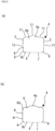
- Fig. 8 illustrates variations of the sticker member 31.
- Fig. 8(a) illustrates the example described above of the sticker member 31.
- Fig. 8(b) illustrates an example where in the sticker member 31, the first joint 32 is joined to the closing piece 8 serving as the inlet/outlet formation part 4 and the sticker member 31 further extends to a front end side beyond the first joint 32.
- Fig. 8(c) illustrates an example where the entirety of the inlet/outlet formation part 4 is covered with the sticker member 31 and is joined. For example, if the entirety of the closing piece 8 serving as the inlet/outlet formation part 4 is covered with the sticker member 31, as illustrated in Fig.
- a beverage or the like serving as the contents can be prevented from leaking out to the surface of the top lid body 3a from a gap such as the cutout line C or the like that forms a circumference of the closing piece 8.
- the sticker member 31 can cover the gap described above. By doing this, even in a situation where the container 21 mounted with the lid 1 is relatively likely to swing, for example, at the time of delivery or takeout or in a situation where the container 21 mounted with the lid 1 is likely to be inclined, the sticker member 31 can avoid leakage to the outside of a beverage serving as the contents that are about to lead out to the outside of the top lid body 3a. By doing this, a lid 1 that reduces leakage can be provided.
- Fig. 8(d) illustrates an example where the sticker member 31 has been formed to cover the inlet/outlet formation part 4 and a width of the tab described above that has been formed at the other end is reduced. This can more reliably avoid, for example, leakage of the beverage described above serving as the contents, and a user can easily hold the other end 31b and can easily perform an operation.
- Fig. 8(e) illustrates an example where a front end portion of the sticker member 31 is flush with a front end of the inlet/outlet formation part 4. By doing this, similarly, a function of the sticker member 31 can be effectively exhibited.
- the sticker member 31 illustrated in Fig. 9 has been formed in such a way that the entirety of the inlet/outlet formation part 4 is covered, an adhesive part at one end of the sticker member 31 (in Fig. 9 , a portion hatched in a small horizontally long rectangular shape) has a great adhesive strength, and an adhesive part at another end of the sticker member 31 (in Fig. 9 , a portion that is located below the hatched portion described above and is illustrated in a horizontally long rectangular shape that is larger than the hatched portion described above) has a small adhesive strength and can be peeled off again. If such formation is employed, the entirety of the inlet/outlet formation part 4 is covered with the sticker member 31. This can reliably avoid a trouble of leakage to the outside of a beverage serving as the contents, for example, even at the time of delivery.
- Fig. 10 is a diagram illustrating a second embodiment.
- Fig. 10 illustrates an example of a lid in which a side wall 2 does not include an upper end side of the side wall 2 described above and the side wall 2 has not been formed to protrude from a top lid body 3a in a top lid 3.
- the present invention can also be applied to a lid 1 having such a shape.
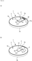
- the lid 1 according to the present embodiment is normally in the state illustrated in Fig. 6(a) .
- the sticker member 31 is joined to a surface of the top lid body 3a of the top lid 3, and the closing piece 8 serving as the inlet/outlet formation part 4 is closed.
- a user holds the tab 34, and peels off a sticker in the second joint 33 that adheres to a side of the other end 31b of the sticker member 31.
- Fig. 6(b) illustrates a state where the sticker in the second joint 33 has been peeled off, as described above. As illustrated in Fig.
- the closing piece 8 serving as the inlet/outlet formation part 4 operates in a direction in which the inlet/outlet S is opened, by using the hinge 6 as a fulcrum. Then, as illustrated in Fig. 6(d) , the closing piece 8 serving as the inlet/outlet formation part 4 operates until the inlet/outlet S is open. Finally, when the closing piece 8 serving as the inlet/outlet formation part 4 has finished operation as described above, a user sticks the sticker member 31 on a surface of the top lid body 3a again. At this time, the sticker in the second joint 33 can adhere again after having been peeled off, and the sticker can be peeled off again, and can adhere again. Therefore, even if the sticker has been peeled off, the sticker can adhere again.
- a lid 1 according to the present invention includes a closing piece 8 serving as an inlet/outlet formation part 4. Therefore, leakage of a beverage or the contents to an outside of the container 21 can be significantly reduced, and a configuration that is conscious of environmental issues can be achieved.
- the inlet/outlet formation part 4 normally covers an inlet/outlet S, and therefore an effect of insulating a beverage serving as the contents from heat can be achieved.
- the lid 1 closes a mouth of a container (not illustrated).
- the lid 1 is made of a material principally including a paper material, and includes a side wall 2 that is fitted to the mouth of the container, and a top lid 3 surrounded by the side wall 2.
- the top lid 3 includes an inlet/outlet formation part 4 that forms an inlet/outlet S of the article stored in the container described above, and a temporary fixing part 51 that temporarily fixes the inlet/outlet formation part 4 to the top lid 3.
- the top lid 3 includes a cutout 52 between an inner edge S1 of the inlet/outlet S and an outer edge 4b of the inlet/outlet formation part 4.
- the top lid 3 includes a top lid edge 53 in a position closer to a side wall 2 than the inlet/outlet formation part 4, and the cutout 52 has been formed between the outer edge 4b of the inlet/outlet formation part 4 and an inner edge of the top lid edge 53.
- the temporary fixing part 51 described above has been formed over the inlet/outlet formation part 4, the cutout 52, and the top lid edge 53 in Fig. 11 .
- the temporary fixing part 51 is temporarily fixed to surfaces of the inlet/outlet formation part 4 and the top lid 3.
- the cutout 52 has a predetermined width H1 between the inner edge S1 of the inlet/outlet S and the outer edge 4b of the inlet/outlet formation part 4.
- a width H2 of the cutout 52 in a portion where the temporary fixing part 51 has been formed has been formed to be different from a width of the cutout 52 in a portion where the temporary fixing part 51 has not been formed.
- the cutout 52 has the width H1 in the portion where the temporary fixing part 51 has been formed, and has the width H2 in the portion where the temporary fixing part 51 has not been formed.
- the widths H1 and H2 have the relationship H2 > H1, and the width H1 of the cutout 52 in a portion where the temporary fixing part 51 has been formed has been formed to be smaller than the width H2 of the cutout 52 in a portion where the temporary fixing part 51 has not been formed.
- the width H2 of the cutout 52 in a portion where the temporary fixing part 51 has not been formed is the same as a width of the cutout 52 before the temporary fixing part 51 is formed. Therefore, Figs. 12 and 13 illustrate a width of the cutout 52 in a state before the temporary fixing part 51 is formed.
- the width H2 of the cutout 52 in a portion where the temporary fixing part 51 has been formed be small, from the viewpoint of avoiding leakage of the contents.
- the width H2 of the cutout 52 in a portion where the temporary fixing part 51 has been formed be 0 (zero) and in other words, the inner edge S1 of the inlet/outlet S be in contact with the outer edge 4b of the inlet/outlet formation part 4. It is more preferable that the inner edge S1 of the inlet/outlet S be in close contact with the outer edge 4b of the inlet/outlet formation part 4 in such a way that a force acts to cause the inner edge S1 and the outer edge 4b to push each other.
- the width of the cutout 52 as described above, the generation of a slight gap between the top lid 3 and the inlet/outlet formation part 4 can be avoided in advance, and this can significantly reduce a risk of leakage of a beverage from the gap in the cutout 52.
- temporary fixing part 51 can be formed by selecting and using an arbitrary conventionally known method, such as ultrasonic joining, various types of thermal fusion including heat sealing, joining using an adhesive, or the like. However, it is preferable that the temporary fixing part 51 be formed by using ultrasonic joining from among conventionally known joining methods. In a case where ultrasonic joining is used, in general, as illustrated in Fig. 12(a) or Fig. 13(a) , a horn 61 and an anvil 62 sandwich a target for joining, ultrasonic waves are applied, and joining is performed.
- a paper material 3P forming the top lid 3 can be made to extend in an X direction in Figs. 12(b) and 13(b) .
- various film members such as a polyethylene film, or the like are laminated on at least one surface of a front surface and a reverse surface of the paper material 3P (in Fig. 13 , both the front surface and the reverse surface)
- these film members F1 and F2 can also be made to extend in the X direction.
- a width of the cutout 52 is reduced and more preferably, the width is reduced to zero. This easily causes contact or close contact. Accordingly, by using ultrasonic joining to form the temporary fixing part 51, a problem of leakage of a beverage serving as the contents can be avoided more reliably.
- the temporary fixing part 51 joins the inlet/outlet formation part 4 (more specifically, the closing piece 8) and the top lid 3 (more specifically, the top lid edge 53) in the top lid 3, as described above. Therefore, the inlet/outlet formation part 4 is temporarily fixed to the top lid 3.
- the temporary fixing part 51 is not limited to such an aspect. In a case where the inlet/outlet formation part 4 is provided with the sticker member 31, as illustrated, for example, in Fig. 11 , the one end 31a of the sticker member 31 may also be joined. Stated another way, in the embodiment described above, description has been provided by using an example where the inlet/outlet formation part 4 is joined to the sticker member 31 in the first joint 32 by using various methods including ultrasonic joining and the like.
- the temporary fixing part 51 may be formed, for example, by shifting a joining portion of the first joint 32. By employing such formation, the temporary fixing part 51 can also be formed together with the first joint 32, and therefore an efficiency of manufacturing the lid 1 can be significantly improved.
- a position of the sticker member 31 in the inlet/outlet formation part 4 can be arbitrarily set.
- a position on a side of the one end 31a of the sticker member 31 be the same as a position on a front end side of the inlet/outlet formation part 4, or be located closer to the hinge 6 than the position on the front end side.
- Fig. 12(a) schematically illustrates a state where ultrasonic joining is performed, by using an example where the top lid 3 is formed by only using the paper material 3P.
- the sticker member 31, the inlet/outlet formation part 4 (the closing piece 8), and the top lid 3 (the top lid edge 53) are sandwiched and pressed by the horn 61 and the anvil 62, and ultrasonic waves are applied. Therefore, joining and temporary fixing can be performed.
- a width H2 of a cutout between the inlet/outlet formation part 4 and the top lid 3 changes to a width H1, as illustrated in Fig. 12(b) , and a width of the cutout 52 decreases. In addition, it is preferable that this width be reduced to zero, as described above. Note that in Fig. 12(b) , unevenness in a portion where the first joint 32 and the temporary fixing part 51 have been formed is a pattern formed in the horn 61.
- Fig. 13(a) illustrates an example where the top lid 3 is obtained by laminating and stacking the paper material 3P and the film members F1 and F2.
- the horn 61 and the anvil 62 sandwich the top lid 3, and ultrasonic waves are applied. Therefore, the first joint 32 and the temporary fixing part 51 can be formed.
- a width of the cutout 52 is similar to the width described with reference to Figs. 12(a) and 12(b) . Note that in a case where the top lid 3 has a configuration in which the paper material 3P and the film members F1 and F2 have been stacked, as illustrated in Figs.
- the paper material 3P can come into contact so that the width of the cutout 52 is reduced to zero, and the film members F1 and F2 can also come into contact so that the width of the cutout 52 is reduced to zero. This can more effectively avoid leakage of the contents (for example, a beverage or the like) of the container 21.
- the pattern illustrated in Fig. 14(b) Effects in a case where ultrasonic joining is performed by using the pattern illustrated in Fig. 14(b) are described.
- the pattern that radially extends can be formed at the top lid edge 53, as illustrated in Fig. 15(a) .
- a paper material forming the top lid 3 is pressed, as described above. Therefore, the pattern is formed in a groove shape on a surface of the top lid 3.
- the pattern formed in the groove shape serves as a guiding part 56.
- the guiding part 56 can guide the beverage through the inlet/outlet S to an inside of the container 21 in such a way that the beverage does not remain at the top lid edge 53. Accordingly, a beverage does not remain at the top lid edge 53, and the lid 1 can be used in a clean state. In addition, clothes or hands are not made dirty due to a beverage remaining at the top lid edge 53, and therefore a risk of feeling uncomfortable can be further reduced, and use without feeling uncomfortable can be achieved.
- the inlet/outlet formation part 4 can be opened more easily in a case where the other end of the sticker member 31 is pulled to open the inlet/outlet formation part 4.
- the inlet/outlet formation part 4 can also be opened at a smaller force.
- a lid according to the present invention has been described in detail above. However, the description above is merely examples of a lid according to the present invention, and a lid according to the present invention is not limited to the examples described above. Accordingly, a lid according to the present invention can be appropriately modified without departing from the scope of the present invention as set forth in the appended claims.
Landscapes
- Engineering & Computer Science (AREA)
- Mechanical Engineering (AREA)
- Closures For Containers (AREA)
- Packages (AREA)
- Cartons (AREA)
Claims (13)
- Deckel (1) zum Schließen einer Öffnung eines Behälters, der aus einem Material besteht, das hauptsächlich ein Papiermaterial umfasst, wobei der Deckel (1) Folgendes umfasst:eine Seitenwand (2) zur Montage an der Öffnung des Behälters und einen oberen Deckel (3), der von der Seitenwand (2) umgeben ist, wobeider obere Deckel (3) Folgendes umfasst:einen Einlass-/Auslassbildungsteil (4), der einen Einlass/Auslass für einen in dem Behälter aufbewahrten Artikel bildet; undder Einlass-/Auslassbildungsteil (4) mit einem Stickerelement (31) montiert ist, wobeider Einlass-/Auslassbildungsteil (4) einen Einlass/Auslass und ein Verschlussteil (8) zum Verschließen des Einlasses/Auslasses umfasst, wobei das Stickerelement (31) mit dem Verschlussteil (8) verbunden ist,das Stickerelement (31) ein Ende (31a) umfasst, das am Verschlussteil (8) montiert ist, und ein weiteres Ende (31b), das dem einen Ende (31a) entgegengesetzt ist, und wobei das weitere Ende (31b) des Stickerelements (31) abziehbar auf einer Fläche des oberen Deckels (3) montiert ist,ein erstes Verbindungsstück (32) mit dem Verschlussteil verbunden ist und an dem einen Ende (31a) des Stickerelements (31) ausgebildet ist,das Verschlussteil (8) ein Ende (8a) aufweist, das von der Mitte des oberen Deckels entfernt angeordnet und ein freies Ende ist, und ein weiteres Ende (8b), das in der Nähe der Mitte des oberen Deckels angeordnet und ein fixiertes Ende ist,und das Verschlussteil (8) dazu ausgelegt ist, durch ein am weiteren Ende (8b) des Verschlussteils (8) ausgebildetes Scharnier (6) geöffnet/geschlossen zu werden.
- Deckel nach Anspruch 1, wobei das Stickerelement (31) am Einlass-/Auslassbildungsteil (4) an einer Position montiert ist, die von der Mitte des Einlass-/Auslassbildungsteils (4) abweicht.
- Deckel nach einem der Ansprüche 1 bis 2, wobei das Stickerelement (31) an einer von der Mitte des oberen Deckels (3) entfernten Position am Einlass-/Auslassbildungsteil (4) montiert ist.
- Deckel nach Anspruch 1, wobei das andere Ende (31b) des Stickerelements (31) in einer festgelegten Position in einer festgelegten Entfernung von dem weiteren Ende (31b) des Stickerelements (31) abziehbar auf der Fläche des oberen Deckels (3) montiert ist.
- Deckel nach Anspruch 1, wobei
das weitere Ende (31b) des Stickerelements (31) eine Lasche (34) umfasst. - Deckel nach Anspruch 5, wobei die Lasche (34) frei ausgebildet und nicht mit der Fläche des oberen Deckels (3) verbunden ist.
- Deckel nach einem der Ansprüche 1 bis 6, wobei das weitere Ende (31b) des Stickerelements (31) ausgebildet ist, um nach dem Abziehen von der Fläche des oberen Deckels (3) erneut montierbar zu sein.
- Deckel nach einem der Ansprüche 1 bis 7, wobei am Stickerelement (31) die Montagefestigkeit an dem einen Ende (31a) größer ist als die Montagefestigkeit am weiteren Ende (31b).
- Deckel nach einem der Ansprüche 1 bis 8, wobei das Stickerelement (31) dazu vorgesehen ist, zumindest einen Teil des Einlass-/Auslassbildungsteils (4) zu bedecken.
- Deckel nach einem der Ansprüche 1 bis 9, wobei das Stickerelement (31) eine Breite aufweist, die größer oder gleich der Breite des Einlass-/Auslassbildungsteils (4) ist.
- Deckel nach Anspruch 1, wobei
das Stickerelement (31) dazu angeordnet ist, zu bewirken, dass sich das eine Ende (31a) über ein Ende des Einlass-/Auslassbildungsteils (4) erstreckt. - Deckel nach Anspruch 1, wobei
das eine Ende (31a) des Stickerelements (31) einen Abschnitt umfasst, der mit einer Fläche des oberen Deckels (3) verbunden ist, oder wobei das eine Ende (31a) des Stickerelements (31) einen Abschnitt umfasst, der nicht mit einer Fläche des oberen Deckels (3) verbunden ist. - Teilesatz, umfassend einen Behälter mit einer Öffnung und dem Deckel nach einem der Ansprüche 1-12 zum Verschließen der Öffnung des Behälters.
Applications Claiming Priority (3)
| Application Number | Priority Date | Filing Date | Title |
|---|---|---|---|
| US201962880356P | 2019-07-30 | 2019-07-30 | |
| US201962886670P | 2019-08-14 | 2019-08-14 | |
| PCT/JP2020/029245 WO2021020511A1 (ja) | 2019-07-30 | 2020-07-30 | 蓋体 |
Publications (3)
| Publication Number | Publication Date |
|---|---|
| EP4005939A1 EP4005939A1 (de) | 2022-06-01 |
| EP4005939A4 EP4005939A4 (de) | 2023-08-23 |
| EP4005939B1 true EP4005939B1 (de) | 2025-05-14 |
Family
ID=74230402
Family Applications (1)
| Application Number | Title | Priority Date | Filing Date |
|---|---|---|---|
| EP20846187.1A Active EP4005939B1 (de) | 2019-07-30 | 2020-07-30 | Deckelkörper |
Country Status (10)
| Country | Link |
|---|---|
| US (1) | US20220258932A1 (de) |
| EP (1) | EP4005939B1 (de) |
| JP (1) | JP6952217B2 (de) |
| KR (2) | KR20250038833A (de) |
| CN (1) | CN114144366B (de) |
| CA (1) | CA3144904A1 (de) |
| ES (1) | ES3033552T3 (de) |
| MX (1) | MX2022001173A (de) |
| TW (2) | TWI846620B (de) |
| WO (1) | WO2021020511A1 (de) |
Families Citing this family (22)
| Publication number | Priority date | Publication date | Assignee | Title |
|---|---|---|---|---|
| CA3144102A1 (en) * | 2019-07-03 | 2021-01-07 | Lgab Llc | Pulp container with fused junction and method of making same |
| US12091220B2 (en) * | 2020-06-04 | 2024-09-17 | Ky7 Inc. | Lid |
| JP1679511S (ja) * | 2020-07-16 | 2021-02-22 | 包装用容器の蓋 | |
| JP1679510S (ja) * | 2020-07-16 | 2021-02-22 | 包装用容器の蓋 | |
| JP1680013S (ja) * | 2020-07-16 | 2021-02-22 | 包装用容器の蓋 | |
| JP1679584S (ja) * | 2020-07-16 | 2021-02-22 | 包装用容器の蓋 | |
| JP1679580S (ja) * | 2020-07-16 | 2021-02-22 | 包装用容器の蓋 | |
| JP1679936S (ja) * | 2020-07-16 | 2021-02-22 | 包装用容器の蓋 | |
| JP1679578S (ja) * | 2020-07-16 | 2021-02-22 | 包装用容器の蓋 | |
| JP1679509S (ja) * | 2020-07-16 | 2021-02-22 | 包装用容器の蓋 | |
| JP1679579S (ja) * | 2020-07-16 | 2021-02-22 | 包装用容器の蓋 | |
| JP1679583S (ja) * | 2020-07-16 | 2021-02-22 | 包装用容器の蓋 | |
| JP1679581S (ja) * | 2020-07-16 | 2021-02-22 | 包装用容器の蓋 | |
| JP1679582S (ja) * | 2020-07-16 | 2021-02-22 | 包装用容器の蓋 | |
| JP7162391B1 (ja) * | 2021-06-15 | 2022-10-28 | 株式会社Ky7 | 蓋体、容器と蓋体の組み合わせ、及び蓋体付き容器 |
| JP7672896B2 (ja) * | 2021-06-30 | 2025-05-08 | 東罐興業株式会社 | 飲料容器用蓋、飲料容器用蓋の飲口形成方法、及び飲料容器 |
| WO2023281837A1 (ja) * | 2021-07-07 | 2023-01-12 | 東罐興業株式会社 | 飲料容器用蓋、飲料容器用蓋の飲口形成方法、及び飲料容器 |
| JP7504556B2 (ja) * | 2021-07-16 | 2024-06-24 | 東罐興業株式会社 | 飲料容器用蓋、飲料容器用蓋の飲口形成方法、及び飲料容器 |
| CN117615976A (zh) * | 2022-06-22 | 2024-02-27 | 株式会社Ky7 | 盖体、带盖体的容器、盖体与容器的组合 |
| JP7450290B1 (ja) * | 2022-06-22 | 2024-03-15 | 株式会社Ky7 | 蓋体、蓋体付き容器、蓋体と容器の組み合わせ |
| CN117813245A (zh) * | 2022-07-20 | 2024-04-02 | 株式会社Ky7 | 盖体、带盖体的容器、盖体与容器的组合 |
| KR20250104503A (ko) * | 2023-12-29 | 2025-07-08 | 김일광 | 토출구 개폐수단이 구비되는 종이플레이트 및 종이플레이트로 제조된 종이캡 |
Citations (1)
| Publication number | Priority date | Publication date | Assignee | Title |
|---|---|---|---|---|
| WO2016069755A1 (en) * | 2014-10-29 | 2016-05-06 | Westrock Mwv, Llc | Paperboard cup lids and methods for making the same |
Family Cites Families (41)
| Publication number | Priority date | Publication date | Assignee | Title |
|---|---|---|---|---|
| US3441163A (en) * | 1967-11-14 | 1969-04-29 | Aluminum Co Of America | Container closure having attached pull tab |
| US3977562A (en) * | 1975-07-22 | 1976-08-31 | Theresa Marie Wedzik | Plastic lid with pull |
| US3990603A (en) * | 1975-12-09 | 1976-11-09 | Minnesota Mining And Manufacturing Company | Easy open closure system |
| US4108330A (en) * | 1977-06-08 | 1978-08-22 | Minnesota Mining And Manufacturing Company | Easy open container end assembly |
| ES244322Y (es) * | 1977-06-08 | 1981-09-16 | Un conjunto de extremo de recipiente. | |
| US4138033A (en) * | 1978-01-16 | 1979-02-06 | Payne Larry E | Liquid container lid |
| US4189060A (en) * | 1978-10-05 | 1980-02-19 | Minnesota Mining And Manufacturing Company | Retention means for container closure assembly |
| US4325490A (en) * | 1980-10-16 | 1982-04-20 | The Continental Group, Inc. | Non-detachable ring pull opening device for beverage cans |
| CH653305A5 (de) * | 1982-03-05 | 1985-12-31 | Alusuisse | Verfahren zum herstellen eines dosendeckels. |
| US4433808A (en) * | 1982-05-03 | 1984-02-28 | International Paper Company | Pourable, recloseable lid |
| SE462034B (sv) * | 1983-05-19 | 1990-04-30 | Akerlund & Rausing Licens Ab | Oeppningsanordning foer foerpackningar |
| CH666458A5 (de) * | 1985-04-24 | 1988-07-29 | Sandherr Packungen Ag | Verpackungsbehaelter. |
| US4760934A (en) * | 1986-05-09 | 1988-08-02 | Fiberplastics, Inc. | Lift tab lid with accordian hinge |
| DE3726162A1 (de) * | 1987-08-06 | 1989-02-16 | Bosch Gmbh Robert | Verpackungsbehaelter mit aufreisseinrichtung |
| JP3596684B2 (ja) * | 1994-05-31 | 2004-12-02 | 日本テトラパック株式会社 | 液体収納容器用プルタブ |
| JP3741389B2 (ja) * | 1995-10-02 | 2006-02-01 | 東罐興業株式会社 | 容器の蓋 |
| JPH1016956A (ja) * | 1996-07-02 | 1998-01-20 | Seiji Kagawa | プルトップ式密封容器 |
| JPH11105819A (ja) * | 1997-09-30 | 1999-04-20 | Lion Corp | 整列装置および整列方法 |
| JP3964967B2 (ja) * | 1997-10-03 | 2007-08-22 | 株式会社ブルボン | 紙製容器 |
| JP2000053126A (ja) * | 1998-08-05 | 2000-02-22 | Nihon Tetra Pak Kk | 包装容器 |
| JP2002211617A (ja) * | 2001-01-18 | 2002-07-31 | Dainippon Printing Co Ltd | 嵌合蓋付きカップ状容器 |
| JP4273773B2 (ja) * | 2003-01-24 | 2009-06-03 | 東洋製罐株式会社 | リシール性を備えた易開封性容器蓋の製法 |
| US6955289B2 (en) * | 2004-02-06 | 2005-10-18 | Lid Lock Cup Co. Ltd. | Container having an integral lid |
| MX2007004370A (es) * | 2006-04-12 | 2008-12-01 | Dixie Consumer Products Llc | Tapa para vaso que se puede volver a cerrar. |
| JP2008308225A (ja) * | 2007-06-18 | 2008-12-25 | Dainippon Printing Co Ltd | 飲み口を有する蓋体 |
| US8672163B2 (en) * | 2009-01-14 | 2014-03-18 | Yeong Leul Kim | Reinforced paper lid |
| JP5445993B2 (ja) * | 2009-02-12 | 2014-03-19 | グリコ乳業株式会社 | ストロー差込部位保護の容器入り飲食物及び該ストロー差込部位保護の容器 |
| JP5427451B2 (ja) * | 2009-03-27 | 2014-02-26 | ユニ・チャーム株式会社 | 包装体 |
| JP5815289B2 (ja) * | 2011-06-01 | 2015-11-17 | 凸版印刷株式会社 | 密閉ラベルおよび包装容器 |
| JP2013018539A (ja) * | 2011-07-14 | 2013-01-31 | Shikoku Kakoki Co Ltd | 容器蓋および容器蓋スタック |
| JP6320384B2 (ja) * | 2012-08-22 | 2018-05-09 | ピーティーエム・パッケージング・ツールズ・マシネリー・ピーティーイー.・リミテッド | 紙ベースの容器蓋 |
| JP2014061948A (ja) * | 2013-10-23 | 2014-04-10 | Uni Charm Corp | 包装体 |
| JP2015140215A (ja) * | 2014-01-30 | 2015-08-03 | 山田 菊夫 | ワイプ収納容器及びワイプディスペンサ |
| JP6454186B2 (ja) | 2015-03-12 | 2019-01-16 | 東罐興業株式会社 | 蓋付き容器 |
| CN107922091B (zh) * | 2015-08-18 | 2020-02-18 | 凸版印刷株式会社 | 纸容器及其制造方法 |
| JPWO2018030482A1 (ja) * | 2016-08-10 | 2019-06-13 | 山田 菊夫 | 吸収性物品及び吸収性物品の製造方法 |
| EP3841029B1 (de) * | 2018-08-22 | 2024-06-12 | Graphic Packaging International, LLC | Deckel mit ausgabefunktion |
| JP7206783B2 (ja) * | 2018-10-17 | 2023-01-18 | 大日本印刷株式会社 | 容器 |
| KR102556137B1 (ko) * | 2018-11-16 | 2023-07-14 | 기쿠오 야마다 | 종이제 뚜껑 및 종이제 뚜껑의 제조방법 |
| EP4005940B1 (de) * | 2020-01-10 | 2026-03-11 | KY7 Inc. | Deckel mit einem halteabschnitt zum halten eines deckelstücks |
| US12091220B2 (en) * | 2020-06-04 | 2024-09-17 | Ky7 Inc. | Lid |
-
2020
- 2020-07-30 ES ES20846187T patent/ES3033552T3/es active Active
- 2020-07-30 WO PCT/JP2020/029245 patent/WO2021020511A1/ja not_active Ceased
- 2020-07-30 JP JP2021515053A patent/JP6952217B2/ja active Active
- 2020-07-30 KR KR1020257007838A patent/KR20250038833A/ko active Pending
- 2020-07-30 EP EP20846187.1A patent/EP4005939B1/de active Active
- 2020-07-30 CN CN202080052997.9A patent/CN114144366B/zh active Active
- 2020-07-30 US US17/631,283 patent/US20220258932A1/en active Pending
- 2020-07-30 KR KR1020227002748A patent/KR102781626B1/ko active Active
- 2020-07-30 MX MX2022001173A patent/MX2022001173A/es unknown
- 2020-07-30 CA CA3144904A patent/CA3144904A1/en active Pending
-
2021
- 2021-02-03 TW TW112138807A patent/TWI846620B/zh active
- 2021-02-03 TW TW110104008A patent/TWI834021B/zh active
Patent Citations (1)
| Publication number | Priority date | Publication date | Assignee | Title |
|---|---|---|---|---|
| WO2016069755A1 (en) * | 2014-10-29 | 2016-05-06 | Westrock Mwv, Llc | Paperboard cup lids and methods for making the same |
Also Published As
| Publication number | Publication date |
|---|---|
| JPWO2021020511A1 (ja) | 2021-09-13 |
| JP6952217B2 (ja) | 2021-10-20 |
| TW202204229A (zh) | 2022-02-01 |
| CA3144904A1 (en) | 2021-02-04 |
| WO2021020511A1 (ja) | 2021-02-04 |
| KR20250038833A (ko) | 2025-03-19 |
| CN114144366A (zh) | 2022-03-04 |
| US20220258932A1 (en) | 2022-08-18 |
| CN118637195A (zh) | 2024-09-13 |
| EP4005939A1 (de) | 2022-06-01 |
| ES3033552T3 (en) | 2025-08-05 |
| KR102781626B1 (ko) | 2025-03-17 |
| BR112022000966A2 (pt) | 2022-03-22 |
| MX2022001173A (es) | 2022-02-22 |
| CN114144366B (zh) | 2024-08-23 |
| TWI834021B (zh) | 2024-03-01 |
| EP4005939A4 (de) | 2023-08-23 |
| TW202404872A (zh) | 2024-02-01 |
| TWI846620B (zh) | 2024-06-21 |
| KR20220038071A (ko) | 2022-03-25 |
Similar Documents
| Publication | Publication Date | Title |
|---|---|---|
| EP4005939B1 (de) | Deckelkörper | |
| US11685576B2 (en) | Lid | |
| US20240270455A1 (en) | Lid, combination of container and lid, and container with lid | |
| CN118637195B (zh) | 盖体 | |
| WO2023228998A1 (ja) | 蓋体、蓋体付き容器、蓋体と容器の組み合わせ、及び蓋体の製造方法 | |
| BR112022000966B1 (pt) | Tampa e kit de partes | |
| JP2025170207A (ja) | 蓋体、容器と蓋体の組み合わせ、及び蓋体付き容器 | |
| HK40130262A (zh) | 盖体、带盖体的容器、盖体与容器的组合 |
Legal Events
| Date | Code | Title | Description |
|---|---|---|---|
| STAA | Information on the status of an ep patent application or granted ep patent |
Free format text: STATUS: THE INTERNATIONAL PUBLICATION HAS BEEN MADE |
|
| PUAI | Public reference made under article 153(3) epc to a published international application that has entered the european phase |
Free format text: ORIGINAL CODE: 0009012 |
|
| STAA | Information on the status of an ep patent application or granted ep patent |
Free format text: STATUS: REQUEST FOR EXAMINATION WAS MADE |
|
| 17P | Request for examination filed |
Effective date: 20220224 |
|
| AK | Designated contracting states |
Kind code of ref document: A1 Designated state(s): AL AT BE BG CH CY CZ DE DK EE ES FI FR GB GR HR HU IE IS IT LI LT LU LV MC MK MT NL NO PL PT RO RS SE SI SK SM TR |
|
| DAV | Request for validation of the european patent (deleted) | ||
| DAX | Request for extension of the european patent (deleted) | ||
| P01 | Opt-out of the competence of the unified patent court (upc) registered |
Effective date: 20230527 |
|
| REG | Reference to a national code |
Ref country code: DE Ref legal event code: R079 Free format text: PREVIOUS MAIN CLASS: B65D0003000000 Ipc: B65D0003060000 Ref country code: DE Ref legal event code: R079 Ref document number: 602020051381 Country of ref document: DE Free format text: PREVIOUS MAIN CLASS: B65D0003000000 Ipc: B65D0003060000 |
|
| A4 | Supplementary search report drawn up and despatched |
Effective date: 20230721 |
|
| RIC1 | Information provided on ipc code assigned before grant |
Ipc: B65D 43/14 20060101ALI20230717BHEP Ipc: B65D 3/26 20060101ALI20230717BHEP Ipc: B65D 47/36 20060101ALI20230717BHEP Ipc: B65D 3/06 20060101AFI20230717BHEP |
|
| STAA | Information on the status of an ep patent application or granted ep patent |
Free format text: STATUS: EXAMINATION IS IN PROGRESS |
|
| 17Q | First examination report despatched |
Effective date: 20240321 |
|
| GRAP | Despatch of communication of intention to grant a patent |
Free format text: ORIGINAL CODE: EPIDOSNIGR1 |
|
| STAA | Information on the status of an ep patent application or granted ep patent |
Free format text: STATUS: GRANT OF PATENT IS INTENDED |
|
| INTG | Intention to grant announced |
Effective date: 20241204 |
|
| GRAS | Grant fee paid |
Free format text: ORIGINAL CODE: EPIDOSNIGR3 |
|
| GRAA | (expected) grant |
Free format text: ORIGINAL CODE: 0009210 |
|
| STAA | Information on the status of an ep patent application or granted ep patent |
Free format text: STATUS: THE PATENT HAS BEEN GRANTED |
|
| AK | Designated contracting states |
Kind code of ref document: B1 Designated state(s): AL AT BE BG CH CY CZ DE DK EE ES FI FR GB GR HR HU IE IS IT LI LT LU LV MC MK MT NL NO PL PT RO RS SE SI SK SM TR |
|
| REG | Reference to a national code |
Ref country code: GB Ref legal event code: FG4D |
|
| REG | Reference to a national code |
Ref country code: CH Ref legal event code: EP |
|
| REG | Reference to a national code |
Ref country code: DE Ref legal event code: R096 Ref document number: 602020051381 Country of ref document: DE |
|
| REG | Reference to a national code |
Ref country code: IE Ref legal event code: FG4D |
|
| REG | Reference to a national code |
Ref country code: ES Ref legal event code: FG2A Ref document number: 3033552 Country of ref document: ES Kind code of ref document: T3 Effective date: 20250805 |
|
| REG | Reference to a national code |
Ref country code: NL Ref legal event code: MP Effective date: 20250514 |
|
| PG25 | Lapsed in a contracting state [announced via postgrant information from national office to epo] |
Ref country code: FI Free format text: LAPSE BECAUSE OF FAILURE TO SUBMIT A TRANSLATION OF THE DESCRIPTION OR TO PAY THE FEE WITHIN THE PRESCRIBED TIME-LIMIT Effective date: 20250514 Ref country code: PT Free format text: LAPSE BECAUSE OF FAILURE TO SUBMIT A TRANSLATION OF THE DESCRIPTION OR TO PAY THE FEE WITHIN THE PRESCRIBED TIME-LIMIT Effective date: 20250915 |
|
| PGFP | Annual fee paid to national office [announced via postgrant information from national office to epo] |
Ref country code: ES Payment date: 20250827 Year of fee payment: 6 |
|
| PGFP | Annual fee paid to national office [announced via postgrant information from national office to epo] |
Ref country code: DE Payment date: 20250722 Year of fee payment: 6 |
|
| REG | Reference to a national code |
Ref country code: LT Ref legal event code: MG9D |
|
| PG25 | Lapsed in a contracting state [announced via postgrant information from national office to epo] |
Ref country code: NO Free format text: LAPSE BECAUSE OF FAILURE TO SUBMIT A TRANSLATION OF THE DESCRIPTION OR TO PAY THE FEE WITHIN THE PRESCRIBED TIME-LIMIT Effective date: 20250814 Ref country code: GR Free format text: LAPSE BECAUSE OF FAILURE TO SUBMIT A TRANSLATION OF THE DESCRIPTION OR TO PAY THE FEE WITHIN THE PRESCRIBED TIME-LIMIT Effective date: 20250815 |
|
| PG25 | Lapsed in a contracting state [announced via postgrant information from national office to epo] |
Ref country code: NL Free format text: LAPSE BECAUSE OF FAILURE TO SUBMIT A TRANSLATION OF THE DESCRIPTION OR TO PAY THE FEE WITHIN THE PRESCRIBED TIME-LIMIT Effective date: 20250514 Ref country code: PL Free format text: LAPSE BECAUSE OF FAILURE TO SUBMIT A TRANSLATION OF THE DESCRIPTION OR TO PAY THE FEE WITHIN THE PRESCRIBED TIME-LIMIT Effective date: 20250514 |
|
| PGFP | Annual fee paid to national office [announced via postgrant information from national office to epo] |
Ref country code: TR Payment date: 20250804 Year of fee payment: 6 Ref country code: IT Payment date: 20250829 Year of fee payment: 6 |
|
| REG | Reference to a national code |
Ref country code: AT Ref legal event code: MK05 Ref document number: 1794634 Country of ref document: AT Kind code of ref document: T Effective date: 20250514 |
|
| PG25 | Lapsed in a contracting state [announced via postgrant information from national office to epo] |
Ref country code: BG Free format text: LAPSE BECAUSE OF FAILURE TO SUBMIT A TRANSLATION OF THE DESCRIPTION OR TO PAY THE FEE WITHIN THE PRESCRIBED TIME-LIMIT Effective date: 20250514 |
|
| PGFP | Annual fee paid to national office [announced via postgrant information from national office to epo] |
Ref country code: BE Payment date: 20250721 Year of fee payment: 6 Ref country code: GB Payment date: 20250722 Year of fee payment: 6 |
|
| PG25 | Lapsed in a contracting state [announced via postgrant information from national office to epo] |
Ref country code: HR Free format text: LAPSE BECAUSE OF FAILURE TO SUBMIT A TRANSLATION OF THE DESCRIPTION OR TO PAY THE FEE WITHIN THE PRESCRIBED TIME-LIMIT Effective date: 20250514 |
|
| PG25 | Lapsed in a contracting state [announced via postgrant information from national office to epo] |
Ref country code: AT Free format text: LAPSE BECAUSE OF FAILURE TO SUBMIT A TRANSLATION OF THE DESCRIPTION OR TO PAY THE FEE WITHIN THE PRESCRIBED TIME-LIMIT Effective date: 20250514 |
|
| PGFP | Annual fee paid to national office [announced via postgrant information from national office to epo] |
Ref country code: FR Payment date: 20250725 Year of fee payment: 6 |
|
| PG25 | Lapsed in a contracting state [announced via postgrant information from national office to epo] |
Ref country code: RS Free format text: LAPSE BECAUSE OF FAILURE TO SUBMIT A TRANSLATION OF THE DESCRIPTION OR TO PAY THE FEE WITHIN THE PRESCRIBED TIME-LIMIT Effective date: 20250814 |
|
| PG25 | Lapsed in a contracting state [announced via postgrant information from national office to epo] |
Ref country code: IS Free format text: LAPSE BECAUSE OF FAILURE TO SUBMIT A TRANSLATION OF THE DESCRIPTION OR TO PAY THE FEE WITHIN THE PRESCRIBED TIME-LIMIT Effective date: 20250914 |
|
| PG25 | Lapsed in a contracting state [announced via postgrant information from national office to epo] |
Ref country code: LV Free format text: LAPSE BECAUSE OF FAILURE TO SUBMIT A TRANSLATION OF THE DESCRIPTION OR TO PAY THE FEE WITHIN THE PRESCRIBED TIME-LIMIT Effective date: 20250514 |
|
| PG25 | Lapsed in a contracting state [announced via postgrant information from national office to epo] |
Ref country code: DK Free format text: LAPSE BECAUSE OF FAILURE TO SUBMIT A TRANSLATION OF THE DESCRIPTION OR TO PAY THE FEE WITHIN THE PRESCRIBED TIME-LIMIT Effective date: 20250514 Ref country code: SM Free format text: LAPSE BECAUSE OF FAILURE TO SUBMIT A TRANSLATION OF THE DESCRIPTION OR TO PAY THE FEE WITHIN THE PRESCRIBED TIME-LIMIT Effective date: 20250514 |
|
| PG25 | Lapsed in a contracting state [announced via postgrant information from national office to epo] |
Ref country code: CZ Free format text: LAPSE BECAUSE OF FAILURE TO SUBMIT A TRANSLATION OF THE DESCRIPTION OR TO PAY THE FEE WITHIN THE PRESCRIBED TIME-LIMIT Effective date: 20250514 |
|
| PG25 | Lapsed in a contracting state [announced via postgrant information from national office to epo] |
Ref country code: EE Free format text: LAPSE BECAUSE OF FAILURE TO SUBMIT A TRANSLATION OF THE DESCRIPTION OR TO PAY THE FEE WITHIN THE PRESCRIBED TIME-LIMIT Effective date: 20250514 |
|
| PG25 | Lapsed in a contracting state [announced via postgrant information from national office to epo] |
Ref country code: RO Free format text: LAPSE BECAUSE OF FAILURE TO SUBMIT A TRANSLATION OF THE DESCRIPTION OR TO PAY THE FEE WITHIN THE PRESCRIBED TIME-LIMIT Effective date: 20250514 Ref country code: SK Free format text: LAPSE BECAUSE OF FAILURE TO SUBMIT A TRANSLATION OF THE DESCRIPTION OR TO PAY THE FEE WITHIN THE PRESCRIBED TIME-LIMIT Effective date: 20250514 |
|
| REG | Reference to a national code |
Ref country code: DE Ref legal event code: R097 Ref document number: 602020051381 Country of ref document: DE |
|
| REG | Reference to a national code |
Ref country code: CH Ref legal event code: H13 Free format text: ST27 STATUS EVENT CODE: U-0-0-H10-H13 (AS PROVIDED BY THE NATIONAL OFFICE) Effective date: 20260224 |
|
| PG25 | Lapsed in a contracting state [announced via postgrant information from national office to epo] |
Ref country code: LU Free format text: LAPSE BECAUSE OF NON-PAYMENT OF DUE FEES Effective date: 20250730 |
|
| PLBE | No opposition filed within time limit |
Free format text: ORIGINAL CODE: 0009261 |
|
| STAA | Information on the status of an ep patent application or granted ep patent |
Free format text: STATUS: NO OPPOSITION FILED WITHIN TIME LIMIT |
|
| REG | Reference to a national code |
Ref country code: CH Ref legal event code: L10 Free format text: ST27 STATUS EVENT CODE: U-0-0-L10-L00 (AS PROVIDED BY THE NATIONAL OFFICE) Effective date: 20260325 |
|
| 26N | No opposition filed |
Effective date: 20260217 |
|
| PG25 | Lapsed in a contracting state [announced via postgrant information from national office to epo] |
Ref country code: CH Free format text: LAPSE BECAUSE OF NON-PAYMENT OF DUE FEES Effective date: 20250731 |