EP4005945B1 - Anordnung mit einem behälter und einer am behälter befestigten verschlussvorrichtung - Google Patents
Anordnung mit einem behälter und einer am behälter befestigten verschlussvorrichtung Download PDFInfo
- Publication number
- EP4005945B1 EP4005945B1 EP20383031.0A EP20383031A EP4005945B1 EP 4005945 B1 EP4005945 B1 EP 4005945B1 EP 20383031 A EP20383031 A EP 20383031A EP 4005945 B1 EP4005945 B1 EP 4005945B1
- Authority
- EP
- European Patent Office
- Prior art keywords
- cap
- lower ring
- neck
- section
- sector
- Prior art date
- Legal status (The legal status is an assumption and is not a legal conclusion. Google has not performed a legal analysis and makes no representation as to the accuracy of the status listed.)
- Active
Links
Images



Classifications
-
- B—PERFORMING OPERATIONS; TRANSPORTING
- B65—CONVEYING; PACKING; STORING; HANDLING THIN OR FILAMENTARY MATERIAL
- B65D—CONTAINERS FOR STORAGE OR TRANSPORT OF ARTICLES OR MATERIALS, e.g. BAGS, BARRELS, BOTTLES, BOXES, CANS, CARTONS, CRATES, DRUMS, JARS, TANKS, HOPPERS, FORWARDING CONTAINERS; ACCESSORIES, CLOSURES, OR FITTINGS THEREFOR; PACKAGING ELEMENTS; PACKAGES
- B65D55/00—Accessories for container closures not otherwise provided for
- B65D55/16—Devices preventing loss of removable closure members
-
- B—PERFORMING OPERATIONS; TRANSPORTING
- B65—CONVEYING; PACKING; STORING; HANDLING THIN OR FILAMENTARY MATERIAL
- B65D—CONTAINERS FOR STORAGE OR TRANSPORT OF ARTICLES OR MATERIALS, e.g. BAGS, BARRELS, BOTTLES, BOXES, CANS, CARTONS, CRATES, DRUMS, JARS, TANKS, HOPPERS, FORWARDING CONTAINERS; ACCESSORIES, CLOSURES, OR FITTINGS THEREFOR; PACKAGING ELEMENTS; PACKAGES
- B65D2251/00—Details relating to container closures
- B65D2251/10—Details of hinged closures
- B65D2251/1008—Means for locking the closure in open position
-
- B—PERFORMING OPERATIONS; TRANSPORTING
- B65—CONVEYING; PACKING; STORING; HANDLING THIN OR FILAMENTARY MATERIAL
- B65D—CONTAINERS FOR STORAGE OR TRANSPORT OF ARTICLES OR MATERIALS, e.g. BAGS, BARRELS, BOTTLES, BOXES, CANS, CARTONS, CRATES, DRUMS, JARS, TANKS, HOPPERS, FORWARDING CONTAINERS; ACCESSORIES, CLOSURES, OR FITTINGS THEREFOR; PACKAGING ELEMENTS; PACKAGES
- B65D2401/00—Tamper-indicating means
-
- B—PERFORMING OPERATIONS; TRANSPORTING
- B65—CONVEYING; PACKING; STORING; HANDLING THIN OR FILAMENTARY MATERIAL
- B65D—CONTAINERS FOR STORAGE OR TRANSPORT OF ARTICLES OR MATERIALS, e.g. BAGS, BARRELS, BOTTLES, BOXES, CANS, CARTONS, CRATES, DRUMS, JARS, TANKS, HOPPERS, FORWARDING CONTAINERS; ACCESSORIES, CLOSURES, OR FITTINGS THEREFOR; PACKAGING ELEMENTS; PACKAGES
- B65D2401/00—Tamper-indicating means
- B65D2401/15—Tearable part of the closure
-
- B—PERFORMING OPERATIONS; TRANSPORTING
- B65—CONVEYING; PACKING; STORING; HANDLING THIN OR FILAMENTARY MATERIAL
- B65D—CONTAINERS FOR STORAGE OR TRANSPORT OF ARTICLES OR MATERIALS, e.g. BAGS, BARRELS, BOTTLES, BOXES, CANS, CARTONS, CRATES, DRUMS, JARS, TANKS, HOPPERS, FORWARDING CONTAINERS; ACCESSORIES, CLOSURES, OR FITTINGS THEREFOR; PACKAGING ELEMENTS; PACKAGES
- B65D2401/00—Tamper-indicating means
- B65D2401/15—Tearable part of the closure
- B65D2401/20—Frangible elements completely enclosed in closure skirt
-
- B—PERFORMING OPERATIONS; TRANSPORTING
- B65—CONVEYING; PACKING; STORING; HANDLING THIN OR FILAMENTARY MATERIAL
- B65D—CONTAINERS FOR STORAGE OR TRANSPORT OF ARTICLES OR MATERIALS, e.g. BAGS, BARRELS, BOTTLES, BOXES, CANS, CARTONS, CRATES, DRUMS, JARS, TANKS, HOPPERS, FORWARDING CONTAINERS; ACCESSORIES, CLOSURES, OR FITTINGS THEREFOR; PACKAGING ELEMENTS; PACKAGES
- B65D2401/00—Tamper-indicating means
- B65D2401/15—Tearable part of the closure
- B65D2401/30—Tamper-ring remaining connected to closure after initial removal
Definitions
- the invention relates to an assembly comprising a container and a capping device which is equipped with a cap and makes it possible to keep said cap attached to the neck of the container, which avoids losing the cap in nature.
- capping devices are known for keeping a cap attached to a neck of the container.
- Such a capping device is, for example, described in the document EP1406820 Or US2018086510 .
- the capping device comprises a ring which is intended to be retained on the neck of the container, a cap which is intended to cover the orifice of the container so as to close it, two elastic strips connecting the cap to the lower ring and a blocking device arranged to block the cap in an open tilted position.
- Such a closure device is not fully satisfactory.
- this cap is intended to clip onto the neck of the container and cannot be adapted to other types of neck.
- the movement of the cap between the closed position and the tilted open position is a simple pivoting movement, which limits the height of the cap and/or neck that can be used. This limits the applications of said capping device.
- it is not suitable for containers intended to receive carbonated drinks because the pressure prevailing inside such containers would lead to unwanted openings of the cap.
- the blocking device is not suitable for all types of caps and does not provide sufficient reliability to maintain the tilted open position on screwed caps, for example.
- the document FR 3 094 353 A1 describes (the signs in parentheses referring to this document) an assembly comprising: - a container equipped with a neck (2), the neck (2) comprising a distribution orifice (5), a helical thread (11), rotating around an axis (X), which is provided on the neck (2) and a hooking collar (18), - a capping device comprising: • a lower ring (3) fixed axially to the neck (2) and movable in rotation on the neck (2) around said axis (X), said lower ring (3) comprising a first sector (16) which comprises hooking elements (18) which project radially towards the inside of the ring lower (3) and are arranged below the hooking collar (18) so as to axially retain the lower ring (3) on the neck (2) of the container and a second sector (16), the first sector ( 15) and the second sector (16) of the lower ring (3) being articulated to one another so that the second sector (16) pivots relative to the first sector (15) between a lowered position in in which the second
- the blocking device guarantees robust blocking, with a significant angle, of the cap in its tilted open position. Furthermore, compared to a blocking device which would include a tab which would be configured to come against the neck of the container, the proposed arrangement makes it possible to limit the radial dimension of the tab. This is particularly advantageous insofar as a stopper having too large a radial dimension is likely to harm the reliability and yield of bottling operations during which the capping devices are notably transported on conveyors before being put into place. place on the containers.
- such an assembly may have one or more of the following characteristics.
- the tab and the projecting portion are configured such that, when the cap is in the open tilted position and the second section of the lower ring is in the lowered position, the tab and the projecting portion are in contact with each other in an area located in the plane of the attachment collar.
- e1 L - e2 + e3 + e4+ ⁇ with ⁇ between 0.05 and 2 mm.
- the projecting portion projects beyond a lower limit of the external peripheral skirt.
- the first sector of the lower ring comprises a front zone which is diametrically opposite to the second sector and two attachment zones which are each arranged between the front zone of the first sector and the second sector, the elements of hooking being only arranged in the two hooking zones so as to allow radial movement of the ring lower capable of facilitating the passage of a part of the second sector on either side of the attachment collar during the movement of the second sector between the lowered position and the released position.
- the tensile forces to be exerted on the lower ring to allow the second sector to move between the lowered position and the raised position are less, which makes it easier to use the capping device.
- the second sector is devoid of hooking elements.
- the front zone of the first sector is devoid of hooking elements.
- the hooking elements are protuberances which project radially inwards.
- the second sector extends over an angular range of between 90 and 180°.
- the front zone of the first sector extends over an angular range of between 40 and 150°.
- each of the two attachment zones extends over an angular range of between 10 and 90°.
- the first sector and the second sector are separated from each other by two thinned zones in which the lower ring locally has a reduction in radial thickness so as to allow the articulation of the second sector by in relation to the first sector.
- the lower ring has a sufficiently small thickness to allow the second sector to pivot relative to the first sector without the first sector and the second sector being separated from each other by two zones. thinned.
- the external peripheral skirt comprises a notched portion and the elastic strips join said external peripheral skirt in said notched portion.
- the lower ring is connected to the external peripheral skirt by frangible bridges.
- the capping device is molded in one piece.
- the slats and the blocking device are configured such that, during the pivoting movement of the cap between the closed position and the tilted open position, the slats are subjected to a traction force which increases until to an intermediate unstable position then which decreases from said intermediate unstable position towards the open tilted position.
- the opening angle of the cap is greater than 120° and advantageously, greater than or equal to 145°, and for example of the order of 180°.
- the axis By convention, the "radial” orientation is directed orthogonal to the X axis and the axial orientation is directed parallel to the X axis.
- the terms “external” and “internal” are used to define the relative position of a element in relation to a other, with reference to the X axis, an element close to the X axis is thus qualified as internal as opposed to an external element located radially on the periphery.
- upper and lower are used to define the relative position of one element with respect to another with reference to a position in which the orifice 3 of the neck 2 is directed upwards and the plug 1 is in closed position on the neck 2 of the container, an element intended to be placed lower being designated by lower and an element intended to be placed higher being designated by upper.
- front and back are used to define the relative position of one element to another along a diameter perpendicular to the X axis.
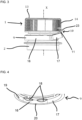
- an assembly is described below comprising a capping device, in particular shown on the figure 1 , and a container equipped with a neck 2, in particular shown on the figure 2 .
- the neck 2 of the container has an upper end in which an orifice 3 is provided allowing the contents of the container to be poured out.
- the neck 2 of the container comprises a support collar 4 which projects radially outwards and a hooking collar 5 which also projects radially outwards and which is arranged axially between the support collar 4 and the orifice 3.
- a cylindrical portion is provided axially between the support collar 4 and the orifice 3.
- the neck 2 comprises, positioned axially between the attachment flange 5 and the orifice 3, a helical thread 6 formed of a series of helical ribs, projecting radially outwards from an external surface of the neck 2.
- the helical thread 6 is intended to cooperate with a complementary helical thread 7, shown in particular on the Figure 5 , formed of a series of helical ribs which are provided in the cap 1 of the capping device.
- the helical thread 6 provided in the neck 2 as well as the helical thread 7 provided in the cap 1 are interrupted.
- the adjacent helical ribs are separated by a space forming a vent and allowing in particular to evacuate the gas present inside the container while the cap 1 is still engaged on the neck 2.
- the capping device comprises a lower ring 9 which is retained on the neck 2 of the container, a cap 1 which is intended to cover the orifice 3 of the container so as to close it and a hinge device 10 connecting the cap 1 to the lower ring 9.
- the cap 1 is movable between a closed position, shown on the figure 1 and a released position, shown on the Figure 3 , in which the cap 1 is no longer engaged with the neck 2.
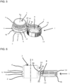
- the cap 1 is also capable of being tilted from the released position to the open tilted position, shown on the figures 5 and 6 , in which the cap 1 is released from the orifice 3 of the neck 2 so that it does not hinder the pouring of the contents of the container.
- the capping device also includes a blocking device arranged to block the cap 1 in the tilted open position.
- the cap 1 has an upper wall 13 intended to be arranged substantially orthogonal to the axis X, facing the orifice 3 of the neck 2 when said cap 1 is in the closed position.
- the cap 1 further comprises an external peripheral skirt 14 intended to surround the neck 2 of the container when the cap 1 is in the closed position.
- the external peripheral skirt 14 extends downwards, perpendicular to the upper wall 13, from the external periphery of said upper wall 13.
- the helical thread 7 is provided on the internal face of the external peripheral skirt 14.
- the cap 1 comprises an internal skirt 8, which extends perpendicularly downwards from the upper wall 13 of the cap 1 and is dimensioned so as to be inserted inside the orifice 3 of the neck 2.
- the cap 1 further comprises an annular lip 15 which extends, from the upper wall 13, radially between the internal skirt 8 and the external peripheral skirt 14.
- the internal skirt 8 and the annular lip 15 are dimensioned such that, when the cap 1 is in the closed position, on the neck 2 of the container, the internal skirt 8 is in contact against the internal face of the neck 2 while the annular lip 15 is in contact against the external face of the neck 2.
- the skirt internal 8 and the annular lip 15 ensure the tightness of the closure.
- the lower ring 9 is, before the first opening of the container, connected to the cap 1 by frangible bridges, not visible in the figures, intended to break when opening the cap 1. These frangible bridges thus constitute witnesses of inviolability.
- the lower ring 9 is held axially on the neck 2 of the container while being able to rotate relative to the latter around the axis figures 1 , 3 and 4 , the lower ring 9 comprises two parts which are articulated to one another, namely a first sector 16 and a second sector 17 by which the lower ring 9 is linked to the plug 1 by means of the articulation device 10.
- the lower ring 9 comprises two thinned zones, that is to say whose radial thickness is less than the radial thickness of the lower ring 9 outside said thinned zones.
- the two thinned zones delimit the first sector 16 and the second sector 17.
- the thinned zones thus form pivots allowing the articulation of the second sector 17 relative to the first sector 16.
- the lower ring 9 does not include no thinned zones delimiting the first and second sectors 16, 17.
- the second sector 17 is capable of pivoting upwards relative to the first sector 16, between a lowered position in which the second sector 17 is intended to be arranged below the attachment flange 5 and a raised position, in which the second sector 17 is arranged at least partly above the attachment flange 5.
- This allows the plug 1 to move upwards relative to the neck 2 of the container, until the helical thread 7 of the cap 1 disengages from the helical thread 6 provided on the neck 2 of the container.
- the lower ring 9 is rotated around the axis raised so as to allow axial movement, upwards of the cap 1, from the closed position, to the released position shown on the Figure 3 .
- the second sector 17 of the lower ring 9 pivots in the opposite direction relative to the first sector 16 and then returns to the lowered position. Furthermore, as described in more detail below, the second sector 17 also pivots relative to the first sector 16 from the lowered position towards the raised position when the cap 1 is pivoted from the open tilted position to the released position.
- the lower ring 9 is held axially on the neck 2 of the container by means of the hooking collar 5.
- the attachment collar 5 has a frustoconical external surface tapering upwards, that is to say in the direction of the orifice 3 of the container.
- the attachment collar 5 delimits, downwards, that is to say in a direction opposite to the orifice 3, a shoulder.
- the first sector 16 of the lower ring 9 comprises hooking elements 18 which cooperate with the hooking collar 5 provided on the container in order to axially retain the lower ring 9 to the neck 2 of the container.
- the hooking elements 18 are protuberances which project radially inwards from the first sector 16 of the lower ring 9.
- the hooking elements 18 have a radial dimension which increases, from bottom to top, this is that is to say towards the upper edge of the lower ring 9.
- the first sector 16 of the lower ring 9 comprises a front zone 19 which is diametrically opposite to the second sector 17 of the lower ring 9 and two attachment zones 20, one of which is shown on the Figure 4 , which are arranged on either side of the front zone 19 and are each arranged between the front zone 19 and the second sector 17 of the lower ring 9.
- the hooking elements 18 are only arranged in the two hooking zones 20, 21.
- the radial clearance e4 between the lower ring 9 and the neck 2 in the front/rear direction is for example between 0.5 and 1 mm. This makes it possible to facilitate the passage of part of the second sector 17 on both sides. other of the attachment collar 5 during the movement of the second sector 17 between the lowered position and the raised position. In other words, the tensile forces to be exerted on the lower ring 9 to allow the second sector 17 to pass on either side of the attachment collar 5 are less.
- the articulation device 10 comprises two lamellae 11, 12, in particular visible on the figure 4 , which connect the plug 1 and more particularly the external peripheral skirt 14 of the plug 1 to the lower ring 9, and more particularly to the second sector 17 of the lower ring 9.
- the strips 11, 12 are symmetrical to each other with respect to a plane of symmetry P, represented on the figures 8 And 9 , which is vertical and passes through the X axis.
- the slats 11, 12 join the external peripheral skirt 14 in a notched portion.
- the strips 11, 12 advantageously join the second sector 17 of the lower ring 2 in a notched portion.
- the strips 11, 12 extend substantially above the lower limit of the external peripheral skirt 9 and extend substantially below the upper limit of the lower ring 3.
- the blocking device includes a heel 22, particularly visible on the figures 1 , 5 and 6 , which is provided in the external peripheral skirt 14 of the cap 1.
- the heel 22 projects axially downwards, that is to say in the direction of the lower ring 9, from the external peripheral skirt 14 of the cap 1.
- the heel 22 projects between the two slats 11, 12.
- the heel 22 includes a tab 23 which extends circumferentially between the two slats 11, 12 and which projects radially outwards from the heel 22.
- the blocking device also comprises a projecting portion 24 which projects axially upwards, that is to say towards the external peripheral skirt 14 of the plug 1, from the second sector 17 of the lower ring 9.
- the portion in projection 24 also projects between the two strips 11, 12.
- the tab 23 and the projecting portion 24 are arranged such that, when the cap 1 is in the tilted open position, the projecting portion 24 is sandwiched between the tab 23 and the collar hooking 5. In other words, when the cap is in the open tilted position, the tab 23 and the projecting portion 24 are in contact with one another in a zone located in the plane of the flange d hooking 5 and the projecting portion 24 is also in contact against the hooking collar 5.
- the contact zone of the tab 23 with the projecting portion 24 is placed at a radial distance e1 from the intersection between the straight line passing through the upper ends of the strips 11, 12 and the plane of symmetry P and the contact zone of the projecting portion 24 with the tab 23 is placed at a radial distance e2 from the intersection between the line passing through the lower ends of the slats 11, 12 and the plane of symmetry P.
- the dimension e1 is such that e1 > L - e2, with L: the length of the strips 11, 12, in the initial state, when the cap is in the closed position. This ensures that the tab 23 comes into contact against the projecting portion 24 and that the strips 11, 12 are stressed in traction when the plug 1 is in the open tilted position.
- the upper edge of the contact surface of the tab 23 extends axially below the upper end of the strips 11, 12 by a distance d1
- the upper edge of the projecting portion 24 extends axially above the lower end of the slats 11, 12 by a distance d2
- the upper edge of the attachment flange 5 extends axially above the lower end of the slats 11, 12 from a distance d3.
- the distance d1 is less than d2 and d3.
- cap 1 The kinematics of cap 1 are as follows. During the first unscrewing, the cap 1 leaves the closed position and moves away from the lower ring 9 to the released position, illustrated on the Figure 3 . Frangible bridges break during this movement. Furthermore, during this movement of unscrewing the cap 1, the lower ring 9 is rotated around the axis X and the second sector 17 of the lower ring 9 pivots towards the raised position as the cap 1 moves away from the attachment collar 5.
- the cap 1 can then be pivoted rearward towards the open tilted position in which the outer peripheral skirt 14 extends upwards from the upper wall 13.
- the tab 23 comes to bear against the projecting portion 24 and thus causes the pivoting of the second sector 17 of the lower ring 9 pivots from the raised position to the lowered position.
- the slats 11, 12 as well as the blocking device are configured such that, during a first part of the movement of the plug 4 from the released position to the open tilted position, the two elastic slats 28, 29 are, due to the support of the cleat 23 on the projecting portion 24, subjected to a traction force which increases to an intermediate unstable position then which decreases from said intermediate unstable position towards the open tilted position. This makes it possible to block the cap 1 in the tilted open position.
- the cap 1 remains in its tilted open position since, due to the aforementioned arrangement, the cap 1 cannot be pivoted towards the released position in which the plug 1 faces the distribution orifice 3 as long as the second sector 17 of the lower ring 9 remains in the lowered position.
- the opening angle of the cap 1 is greater than 120° and advantageously, greater than or equal to 145° and for example of the order of 180°.
- the opening angle corresponds to the protruding angular sector which is formed at the intersection between a plane parallel to the upper wall 13 of the plug 1 and a horizontal plane.
- cap 1 To close cap 1, the user tilts cap 1 forward to the released position. During this tilting, the contact between the tab 23 and the projecting portion 24 disappears, which allows the movement of the second sector 17 of the lower ring 9 towards the raised position.
- the entire closure device is molded in a single piece of synthetic material, such as polyethylene and advantageously high density polyethylene.
- the capping device is molded in the configuration of the figure 1 , that is to say in a closed position, position in which it can be directly mounted on the neck 2 of the container.
Landscapes
- Engineering & Computer Science (AREA)
- Mechanical Engineering (AREA)
- Closures For Containers (AREA)
- Sealing Of Jars (AREA)
- Auxiliary Devices For And Details Of Packaging Control (AREA)
- Dry Development In Electrophotography (AREA)
Claims (10)
- Anordnung umfassend:- einen Behälter, der mit einem Hals (2) ausgestattet ist, wobei der Hals (2) eine Ausgabeöffnung (3), ein Spiralgewinde (6) das sich um eine X-Achse dreht und auf den Hals (2) aufgezogen ist, und einen Einhakkragen (5) aufweist,- eine Verschlussvorrichtung umfassend:∘ einen unteren Ring (9), der axial am Hals (2) befestigt und auf dem Hals (2) um die X-Achse drehbar ist, wobei der untere Ring (9) einen ersten Sektor (16) mit Hakenelementen (18) aufweist, die radial in das Innere des unteren Ringes (9) hervorstehen und unterhalb des Einhakkragens (5) angeordnet sind, um den unteren Ring (9) axial auf dem Hals (2) des Behälters zurück zu halten, und einen zweiten Sektor (17) aufweist, wobei der erste Sektor (16) und der zweite Sektor (17) des unteren Rings (9) so aneinander gegliedert sind, dass der zweite Sektor (17) in Bezug auf den ersten Sektor (16) zwischen einer abgesenkten Position, in der der zweite Sektor (17) unterhalb des Einhakkragens (5) angeordnet ist, und einer angehobenen Position, in der der zweite Sektor (17) zumindest teilweise oberhalb des Einhakkragens (5) angeordnet ist, schwenkt,∘ einen Verschluss (1) mit einer oberen Wand (13) und einer äußeren Umfangsschürze (14), wobei die äußere Umfangsschürze (14) ein Spiralgewinde (7) aufweist, das dazu bestimmt ist, mit dem Spiralgewinde (6) des Halses (2) zusammenzuwirken, so dass der Verschluss (1) zwischen einer geschlossenen und einer befreiten Position, in der das Spiralgewinde (7) des Verschlusses (1) nicht mehr mit dem Spiralgewinde (6) des Halses (2) in Kontakt steht, bewegt werden kann;∘ eine Gelenkvorrichtung (10) mit zwei Lamellen (11, 12), die die äußere Umfangsschürze (14) und den zweiten Sektor (17) verbinden und so konfiguriert sind, dass der Verschluss (1) zwischen der befreiten Position und einer offenen Kippstellung, in welcher der Verschluss (1) von der Ausgabeöffnung (3) des Halses (2) freigelegt ist, schwenken kann; wobei der zweite Sektor (17) des unteren Rings (9) geeignet ist, in der abgesenkten Position gestellt zu werden, wenn sich der Verschluss (1) in der offenen Kippstellung befindet;
wobei die Verschlussvorrichtung ferner eine Blockiervorrichtung umfasst, die zum Blockieren des Verschlusses (1) konfiguriert ist, wenn sich dieser in der offenen Kippstellung befindet, die Blockiervorrichtung umfassend:∘ einen Absatz (22), der axial von der äußeren Umfangsschürze (14) zwischen den beiden Lamellen (11, 12) der Gelenkvorrichtung (10) hervorsteht und einen radial nach außen hervorstehenden Stift (23) aufweist; und∘ einen hervorstehenden Bereich (24), der axial vom zweiten Sektor (17) des unteren Rings (9) zwischen den beiden Lamellen (11, 12) der Gelenkvorrichtung (10) hervorsteht;o der Stift (23) und der hervorstehende Bereich (24) sind in der Weise geformt, dass wenn der Verschluss (1) sich in der offenen Kippstellung befindet und der zweite Sektor des unteren Ringes (9) in der abgesenkten Position ist, der hervorstehende Bereich (24) zwischen dem Stift (23) und dem Einhakkragen (5) eingeklemmt ist. - Anordnung nach Anspruch 1, wobei e1 > L - e2 mit:L: die Länge der Lamellen (11, 12) in einem Anfangszustand, in welchem der Verschluss (1) in der geschlossenen Position;e1: ein radialer Abstand zwischen einem Kontaktbereich des Stifts (23), der dazu bestimmt ist, mit dem hervorstehenden Bereich (24) in Kontakt zu kommen, wenn sich der Verschluss (1) in der offenen Kippstellung befindet, und einem Schnittpunkt zwischen einer Geraden, die durch obere Enden der Lamellen (11, 12) verläuft, und einer Symmetrieebene (P) der Lamellen (11, 12) zueinander; unde2: ein radialer Abstand zwischen einem Kontaktbereich des hervorstehenden Bereichs (24), der dazu bestimmt ist, mit dem Stift (23) in Kontakt zu kommen, wenn sich der Verschluss (1) in der offenen Kippstellung befindet, und einem Schnittpunkt zwischen einer Geraden, die durch untere Enden der Lamellen (11, 12) verläuft, und einer Symmetrieebene (P).
- Anordnung nach Anspruch 2, wobei e1 > L - e2 + e3 + e4 mit:e3 : Radialluft zwischen dem unteren Ring (9) und dem Hals (2) in einer Richtung, die radial zur X-Achse verläuft und in der Symmetrieebene P enthalten ist; unde4: Radialluft zwischen dem hervorstehenden Bereich (24) und dem Einhakkragen (5).
- Anordnung nach Anspruch 3, wobei e1 = L - e2 + e3 + e4 + Δ wobei Δ zwischen 0,05 und 2 mm liegt.
- Anordnung nach einem der Ansprüche 1 bis 4, wobei der hervorstehende Bereich (24) über eine untere Grenze der äußeren Umfangsschürze (14) hervorsteht.
- Anordnung nach einem der Ansprüche 1 bis 5, wobei der erste Sektor (16) des unteren Rings (9) einen vorderen Bereich, der dem zweiten Sektor (17) diametral gegenüberliegt, und zwei Einhakzonen aufweist, die jeweils zwischen dem vorderen Bereich des ersten Sektors (16) und dem zweiten Sektor (17) angeordnet sind, die Einhakelemente nur in den beiden Einhakzonen angeordnet sind, um eine radiale Bewegung des unteren Rings (9) zu ermöglichen, die geeignet ist den Durchgang eines Teils des zweiten Sektors (17) auf beiden Seiten des Einhakkragens (5) während der Bewegung des zweiten Sektors (17) zwischen der abgesenkten Position und der befreiten Position zu erleichtern.
- Anordnung nach einem der Ansprüche 1 bis 6, wobei die Lamellen (11, 12) und die Blockiervorrichtung so konfiguriert sind, dass bei der Schwenkbewegung des Verschlusses (1) zwischen der geschlossenen Stellung und der offenen Kippstellung die Lamellen (11, 12) einer Zugkraft ausgesetzt sind, die bis zu einer instabilen Zwischenstellung zunimmt und dann von der instabilen Zwischenstellung zur offenen Kippstellung abnimmt.
- Anordnung nach einem der Ansprüche 1 bis 7, wobei die Verschlussvorrichtung einstückig geformt wurde.
- Anordnung nach einem der Ansprüche 1 bis 8, bei der untere Ring (9) mit der äußeren Umfangsschürze (14) durch zerbrechliche Brücken verbunden ist.
- Anordnung nach einem der Ansprüche 1 bis 8, wobei, wenn der Verschluss (1) in der offenen Kippstellung ist und der zweite Sektor (17) des unteren Rings (9) in der abgesenkten Position ist, der Öffnungswinkel des Verschlusses (1) größer als 120° ist.
Priority Applications (13)
| Application Number | Priority Date | Filing Date | Title |
|---|---|---|---|
| EP20383031.0A EP4005945B1 (de) | 2020-11-26 | 2020-11-26 | Anordnung mit einem behälter und einer am behälter befestigten verschlussvorrichtung |
| ES20383031T ES2969159T3 (es) | 2020-11-26 | 2020-11-26 | Conjunto que comprende un recipiente y un dispositivo de cierre unido al recipiente |
| PT203830310T PT4005945T (pt) | 2020-11-26 | 2020-11-26 | Conjunto que compreende um recipiente e um dispositivo de colocação de tampa fixado no recipiente |
| UY0001039534A UY39534A (es) | 2020-11-26 | 2021-11-25 | Conjunto que comprende un recipiente y un dispositivo de taponado fijado al recipiente |
| ARP210103263A AR124151A1 (es) | 2020-11-26 | 2021-11-25 | Conjunto que comprende un recipiente y un dispositivo de taponado fijado al recipiente |
| US18/039,145 US20240002116A1 (en) | 2020-11-26 | 2021-11-26 | Assembly Comprising A Container And Plugging Device Attached To The Container |
| CA3200299A CA3200299A1 (en) | 2020-11-26 | 2021-11-26 | Assembly comprising a container and plugging device attached to the container |
| AU2021388924A AU2021388924A1 (en) | 2020-11-26 | 2021-11-26 | Assembly comprising a container and plugging device attached to the container |
| MX2023006239A MX2023006239A (es) | 2020-11-26 | 2021-11-26 | Conjunto que comprende un recipiente y un dispositivo de taponado fijado al recipiente. |
| PCT/EP2021/083150 WO2022112495A1 (fr) | 2020-11-26 | 2021-11-26 | Ensemble comprenant un récipient et un dispositif de bouchage attaché au récipient |
| JP2023532132A JP7618300B2 (ja) | 2020-11-26 | 2021-11-26 | 容器と、容器に取り付けられる閉栓装置とを含むアセンブリ |
| CN202180091640.6A CN116829469A (zh) | 2020-11-26 | 2021-11-26 | 包括容器和附接至容器的封盖装置的组件 |
| CONC2023/0006825A CO2023006825A2 (es) | 2020-11-26 | 2023-05-25 | Conjunto que comprende un recipiente y un dispositivo de taponado fijado al recipiente |
Applications Claiming Priority (1)
| Application Number | Priority Date | Filing Date | Title |
|---|---|---|---|
| EP20383031.0A EP4005945B1 (de) | 2020-11-26 | 2020-11-26 | Anordnung mit einem behälter und einer am behälter befestigten verschlussvorrichtung |
Publications (2)
| Publication Number | Publication Date |
|---|---|
| EP4005945A1 EP4005945A1 (de) | 2022-06-01 |
| EP4005945B1 true EP4005945B1 (de) | 2023-10-11 |
Family
ID=73654761
Family Applications (1)
| Application Number | Title | Priority Date | Filing Date |
|---|---|---|---|
| EP20383031.0A Active EP4005945B1 (de) | 2020-11-26 | 2020-11-26 | Anordnung mit einem behälter und einer am behälter befestigten verschlussvorrichtung |
Country Status (13)
| Country | Link |
|---|---|
| US (1) | US20240002116A1 (de) |
| EP (1) | EP4005945B1 (de) |
| JP (1) | JP7618300B2 (de) |
| CN (1) | CN116829469A (de) |
| AR (1) | AR124151A1 (de) |
| AU (1) | AU2021388924A1 (de) |
| CA (1) | CA3200299A1 (de) |
| CO (1) | CO2023006825A2 (de) |
| ES (1) | ES2969159T3 (de) |
| MX (1) | MX2023006239A (de) |
| PT (1) | PT4005945T (de) |
| UY (1) | UY39534A (de) |
| WO (1) | WO2022112495A1 (de) |
Families Citing this family (1)
| Publication number | Priority date | Publication date | Assignee | Title |
|---|---|---|---|---|
| USD1067776S1 (en) * | 2022-09-08 | 2025-03-25 | Betapack, S.A.U. | Cap |
Family Cites Families (10)
| Publication number | Priority date | Publication date | Assignee | Title |
|---|---|---|---|---|
| FR2349509A2 (fr) * | 1976-04-29 | 1977-11-25 | Alca Sa | Bouchon a vis inviolable en une seule piece de matiere thermoplastique |
| FR2785264B1 (fr) * | 1998-10-29 | 2001-01-05 | Crown Cork & Seal Tech Corp | Dispositif de bouchage |
| FR2827261B1 (fr) | 2001-07-13 | 2003-09-26 | Tetra Laval Holdings & Finance | Dispositif de bouchage et recipient equipe d'un tel dispositif |
| US20110297682A1 (en) * | 2007-06-22 | 2011-12-08 | Si Joong Kwon | Container with anti-loss and anti-idle-rotation cap |
| CA2702174A1 (en) * | 2007-10-10 | 2009-04-16 | Best Easy Cap Co., Ltd. | Container with anti-loss and anti-idle-rotation cap |
| KR100981240B1 (ko) * | 2010-03-23 | 2010-09-10 | 권시중 | 공회전 방지 버팀대가 구비된 포장용기 마개 |
| JP6081738B2 (ja) * | 2012-08-24 | 2017-02-15 | 日本クロージャー株式会社 | 合成樹脂製容器蓋 |
| WO2015061834A1 (en) * | 2013-10-31 | 2015-05-07 | Doran Brian | Capping device for a container |
| MX380988B (es) | 2016-03-04 | 2025-03-12 | Betapack S A U | Tapón para envases. |
| PL73181Y1 (pl) * | 2019-03-28 | 2023-11-20 | Betapack S A U | Urządzenie zakrętkowe przeznaczone do mocowania na szyjce pojemnika |
-
2020
- 2020-11-26 ES ES20383031T patent/ES2969159T3/es active Active
- 2020-11-26 EP EP20383031.0A patent/EP4005945B1/de active Active
- 2020-11-26 PT PT203830310T patent/PT4005945T/pt unknown
-
2021
- 2021-11-25 AR ARP210103263A patent/AR124151A1/es active IP Right Grant
- 2021-11-25 UY UY0001039534A patent/UY39534A/es not_active Application Discontinuation
- 2021-11-26 US US18/039,145 patent/US20240002116A1/en not_active Abandoned
- 2021-11-26 AU AU2021388924A patent/AU2021388924A1/en not_active Abandoned
- 2021-11-26 WO PCT/EP2021/083150 patent/WO2022112495A1/fr not_active Ceased
- 2021-11-26 CA CA3200299A patent/CA3200299A1/en active Pending
- 2021-11-26 JP JP2023532132A patent/JP7618300B2/ja active Active
- 2021-11-26 CN CN202180091640.6A patent/CN116829469A/zh active Pending
- 2021-11-26 MX MX2023006239A patent/MX2023006239A/es unknown
-
2023
- 2023-05-25 CO CONC2023/0006825A patent/CO2023006825A2/es unknown
Also Published As
| Publication number | Publication date |
|---|---|
| ES2969159T3 (es) | 2024-05-16 |
| JP7618300B2 (ja) | 2025-01-21 |
| WO2022112495A1 (fr) | 2022-06-02 |
| MX2023006239A (es) | 2023-06-12 |
| PT4005945T (pt) | 2024-01-04 |
| AU2021388924A9 (en) | 2024-09-12 |
| EP4005945A1 (de) | 2022-06-01 |
| CA3200299A1 (en) | 2022-06-02 |
| CN116829469A (zh) | 2023-09-29 |
| JP2023550803A (ja) | 2023-12-05 |
| AR124151A1 (es) | 2023-02-22 |
| CO2023006825A2 (es) | 2023-08-09 |
| US20240002116A1 (en) | 2024-01-04 |
| UY39534A (es) | 2022-06-30 |
| AU2021388924A1 (en) | 2023-06-29 |
Similar Documents
| Publication | Publication Date | Title |
|---|---|---|
| FR3094353A1 (fr) | Dispositif de bouchage destine a etre fixe sur un col d’un recipient | |
| EP4095061B1 (de) | Verschlussvorrichtung für einen hals eines behälters | |
| EP2889232B1 (de) | Gelenkverschlussvorrichtung mit Anzeige der erstmaligen Öffnung | |
| FR3108317A3 (fr) | Bouchon pour recipient a col filete muni d’un organe de blocage par engagement | |
| EP4026783B1 (de) | Verschlussvorrichtung zur befestigung am hals eines behälters | |
| FR2804661A1 (fr) | Dispositif de bouchage d'un recipient et recipient pourvu d'un tel dispositif | |
| EP3882173B1 (de) | Scharnierdeckel für einen behälter mit einem hals | |
| EP3882172B1 (de) | Kappe für einen behälter mit einem gewindehals, der mit einem blockierorgan durch drücken versehen ist | |
| CA2649461A1 (fr) | Dispositif de bouchage d'un recipient, recipient equipe d'un tel dispositif et procede de fabrication d'un tel dispositif | |
| FR3106582A1 (fr) | Dispositif de capsulage destine a être fixe sur le goulot d’un contenant et ensemble comprenant un contenant et un dispositif de capsulage | |
| EP4026785B1 (de) | Verschlussvorichtung, die einen mit einem beweglichen gelenk an der basis angebrachten verschluss umfasst | |
| FR3106583A1 (fr) | Dispositif de bouchage destiné à être fixé sur le col d’un récipient | |
| EP3889063B1 (de) | Zusammenstellung mit behälter mit gewindehals und kappe mit achsenpositionierungsbeinen und zentrierbeinen | |
| FR2729924A1 (fr) | Flacon de distribution de produit | |
| FR3106584A1 (fr) | Dispositif de bouchage destiné à être fixé sur le col d’un récipient | |
| EP4026782B1 (de) | Verschlussvorrichtung zur befestigung am hals eines behälters | |
| WO2022112495A1 (fr) | Ensemble comprenant un récipient et un dispositif de bouchage attaché au récipient | |
| EP1600394A1 (de) | Kappe mit inneren und äusseren Dichtlippen | |
| FR2913677A1 (fr) | Decapsuleur pour capsule de bouchage du col d'une bouteille. | |
| EP4301669B1 (de) | Kappe mit einem verriegelungsstift | |
| FR2779702A1 (fr) | Dispositif de bouchage a vis de type inviolable | |
| WO2009056769A1 (fr) | Dispositif de bouchage d'un col de récipient | |
| FR2802182A1 (fr) | Bouchon en matiere synthetique comportant un capuchon articule | |
| EP4147985A1 (de) | Vorrichtung zur lagerung einer flüssigkeit mit einem behälter und einem stopfen, der fest mit dem behälter verbunden bleibt | |
| EP4605314A1 (de) | Kappe mit einer führungsrampe für eine nabe |
Legal Events
| Date | Code | Title | Description |
|---|---|---|---|
| PUAI | Public reference made under article 153(3) epc to a published international application that has entered the european phase |
Free format text: ORIGINAL CODE: 0009012 |
|
| STAA | Information on the status of an ep patent application or granted ep patent |
Free format text: STATUS: THE APPLICATION HAS BEEN PUBLISHED |
|
| AK | Designated contracting states |
Kind code of ref document: A1 Designated state(s): AL AT BE BG CH CY CZ DE DK EE ES FI FR GB GR HR HU IE IS IT LI LT LU LV MC MK MT NL NO PL PT RO RS SE SI SK SM TR |
|
| REG | Reference to a national code |
Ref country code: HK Ref legal event code: DE Ref document number: 40071462 Country of ref document: HK |
|
| STAA | Information on the status of an ep patent application or granted ep patent |
Free format text: STATUS: REQUEST FOR EXAMINATION WAS MADE |
|
| 17P | Request for examination filed |
Effective date: 20221128 |
|
| RAV | Requested validation state of the european patent: fee paid |
Extension state: TN Effective date: 20221128 Extension state: MA Effective date: 20221128 |
|
| RBV | Designated contracting states (corrected) |
Designated state(s): AL AT BE BG CH CY CZ DE DK EE ES FI FR GB GR HR HU IE IS IT LI LT LU LV MC MK MT NL NO PL PT RO RS SE SI SK SM TR |
|
| GRAP | Despatch of communication of intention to grant a patent |
Free format text: ORIGINAL CODE: EPIDOSNIGR1 |
|
| STAA | Information on the status of an ep patent application or granted ep patent |
Free format text: STATUS: GRANT OF PATENT IS INTENDED |
|
| INTG | Intention to grant announced |
Effective date: 20230403 |
|
| P01 | Opt-out of the competence of the unified patent court (upc) registered |
Effective date: 20230602 |
|
| GRAJ | Information related to disapproval of communication of intention to grant by the applicant or resumption of examination proceedings by the epo deleted |
Free format text: ORIGINAL CODE: EPIDOSDIGR1 |
|
| STAA | Information on the status of an ep patent application or granted ep patent |
Free format text: STATUS: REQUEST FOR EXAMINATION WAS MADE |
|
| GRAS | Grant fee paid |
Free format text: ORIGINAL CODE: EPIDOSNIGR3 |
|
| STAA | Information on the status of an ep patent application or granted ep patent |
Free format text: STATUS: GRANT OF PATENT IS INTENDED |
|
| GRAP | Despatch of communication of intention to grant a patent |
Free format text: ORIGINAL CODE: EPIDOSNIGR1 |
|
| INTC | Intention to grant announced (deleted) | ||
| GRAA | (expected) grant |
Free format text: ORIGINAL CODE: 0009210 |
|
| STAA | Information on the status of an ep patent application or granted ep patent |
Free format text: STATUS: THE PATENT HAS BEEN GRANTED |
|
| INTG | Intention to grant announced |
Effective date: 20230817 |
|
| AK | Designated contracting states |
Kind code of ref document: B1 Designated state(s): AL AT BE BG CH CY CZ DE DK EE ES FI FR GB GR HR HU IE IS IT LI LT LU LV MC MK MT NL NO PL PT RO RS SE SI SK SM TR |
|
| REG | Reference to a national code |
Ref country code: GB Ref legal event code: FG4D Free format text: NOT ENGLISH |
|
| REG | Reference to a national code |
Ref country code: CH Ref legal event code: EP |
|
| REG | Reference to a national code |
Ref country code: DE Ref legal event code: R096 Ref document number: 602020019013 Country of ref document: DE |
|
| REG | Reference to a national code |
Ref country code: IE Ref legal event code: FG4D Free format text: LANGUAGE OF EP DOCUMENT: FRENCH |
|
| REG | Reference to a national code |
Ref country code: PT Ref legal event code: SC4A Ref document number: 4005945 Country of ref document: PT Date of ref document: 20240104 Kind code of ref document: T Free format text: AVAILABILITY OF NATIONAL TRANSLATION Effective date: 20231227 |
|
| REG | Reference to a national code |
Ref country code: NL Ref legal event code: FP |
|
| REG | Reference to a national code |
Ref country code: LT Ref legal event code: MG9D |
|
| REG | Reference to a national code |
Ref country code: AT Ref legal event code: MK05 Ref document number: 1620032 Country of ref document: AT Kind code of ref document: T Effective date: 20231011 |
|
| PG25 | Lapsed in a contracting state [announced via postgrant information from national office to epo] |
Ref country code: GR Free format text: LAPSE BECAUSE OF FAILURE TO SUBMIT A TRANSLATION OF THE DESCRIPTION OR TO PAY THE FEE WITHIN THE PRESCRIBED TIME-LIMIT Effective date: 20240112 |
|
| PG25 | Lapsed in a contracting state [announced via postgrant information from national office to epo] |
Ref country code: IS Free format text: LAPSE BECAUSE OF FAILURE TO SUBMIT A TRANSLATION OF THE DESCRIPTION OR TO PAY THE FEE WITHIN THE PRESCRIBED TIME-LIMIT Effective date: 20240211 |
|
| PG25 | Lapsed in a contracting state [announced via postgrant information from national office to epo] |
Ref country code: LT Free format text: LAPSE BECAUSE OF FAILURE TO SUBMIT A TRANSLATION OF THE DESCRIPTION OR TO PAY THE FEE WITHIN THE PRESCRIBED TIME-LIMIT Effective date: 20231011 |
|
| PG25 | Lapsed in a contracting state [announced via postgrant information from national office to epo] |
Ref country code: AT Free format text: LAPSE BECAUSE OF FAILURE TO SUBMIT A TRANSLATION OF THE DESCRIPTION OR TO PAY THE FEE WITHIN THE PRESCRIBED TIME-LIMIT Effective date: 20231011 |
|
| PG25 | Lapsed in a contracting state [announced via postgrant information from national office to epo] |
Ref country code: LT Free format text: LAPSE BECAUSE OF FAILURE TO SUBMIT A TRANSLATION OF THE DESCRIPTION OR TO PAY THE FEE WITHIN THE PRESCRIBED TIME-LIMIT Effective date: 20231011 Ref country code: IT Free format text: LAPSE BECAUSE OF NON-PAYMENT OF DUE FEES Effective date: 20231126 Ref country code: IS Free format text: LAPSE BECAUSE OF FAILURE TO SUBMIT A TRANSLATION OF THE DESCRIPTION OR TO PAY THE FEE WITHIN THE PRESCRIBED TIME-LIMIT Effective date: 20240211 Ref country code: GR Free format text: LAPSE BECAUSE OF FAILURE TO SUBMIT A TRANSLATION OF THE DESCRIPTION OR TO PAY THE FEE WITHIN THE PRESCRIBED TIME-LIMIT Effective date: 20240112 Ref country code: BG Free format text: LAPSE BECAUSE OF FAILURE TO SUBMIT A TRANSLATION OF THE DESCRIPTION OR TO PAY THE FEE WITHIN THE PRESCRIBED TIME-LIMIT Effective date: 20240111 Ref country code: AT Free format text: LAPSE BECAUSE OF FAILURE TO SUBMIT A TRANSLATION OF THE DESCRIPTION OR TO PAY THE FEE WITHIN THE PRESCRIBED TIME-LIMIT Effective date: 20231011 |
|
| REG | Reference to a national code |
Ref country code: ES Ref legal event code: FG2A Ref document number: 2969159 Country of ref document: ES Kind code of ref document: T3 Effective date: 20240516 |
|
| PG25 | Lapsed in a contracting state [announced via postgrant information from national office to epo] |
Ref country code: SE Free format text: LAPSE BECAUSE OF FAILURE TO SUBMIT A TRANSLATION OF THE DESCRIPTION OR TO PAY THE FEE WITHIN THE PRESCRIBED TIME-LIMIT Effective date: 20231011 Ref country code: RS Free format text: LAPSE BECAUSE OF FAILURE TO SUBMIT A TRANSLATION OF THE DESCRIPTION OR TO PAY THE FEE WITHIN THE PRESCRIBED TIME-LIMIT Effective date: 20231011 Ref country code: PL Free format text: LAPSE BECAUSE OF FAILURE TO SUBMIT A TRANSLATION OF THE DESCRIPTION OR TO PAY THE FEE WITHIN THE PRESCRIBED TIME-LIMIT Effective date: 20231011 Ref country code: NO Free format text: LAPSE BECAUSE OF FAILURE TO SUBMIT A TRANSLATION OF THE DESCRIPTION OR TO PAY THE FEE WITHIN THE PRESCRIBED TIME-LIMIT Effective date: 20240111 Ref country code: LV Free format text: LAPSE BECAUSE OF FAILURE TO SUBMIT A TRANSLATION OF THE DESCRIPTION OR TO PAY THE FEE WITHIN THE PRESCRIBED TIME-LIMIT Effective date: 20231011 Ref country code: HR Free format text: LAPSE BECAUSE OF FAILURE TO SUBMIT A TRANSLATION OF THE DESCRIPTION OR TO PAY THE FEE WITHIN THE PRESCRIBED TIME-LIMIT Effective date: 20231011 |
|
| REG | Reference to a national code |
Ref country code: CH Ref legal event code: PL |
|
| PG25 | Lapsed in a contracting state [announced via postgrant information from national office to epo] |
Ref country code: DK Free format text: LAPSE BECAUSE OF FAILURE TO SUBMIT A TRANSLATION OF THE DESCRIPTION OR TO PAY THE FEE WITHIN THE PRESCRIBED TIME-LIMIT Effective date: 20231011 |
|
| REG | Reference to a national code |
Ref country code: DE Ref legal event code: R097 Ref document number: 602020019013 Country of ref document: DE |
|
| PG25 | Lapsed in a contracting state [announced via postgrant information from national office to epo] |
Ref country code: LU Free format text: LAPSE BECAUSE OF NON-PAYMENT OF DUE FEES Effective date: 20231126 |
|
| PG25 | Lapsed in a contracting state [announced via postgrant information from national office to epo] |
Ref country code: CH Free format text: LAPSE BECAUSE OF NON-PAYMENT OF DUE FEES Effective date: 20231130 |
|
| PG25 | Lapsed in a contracting state [announced via postgrant information from national office to epo] |
Ref country code: CZ Free format text: LAPSE BECAUSE OF FAILURE TO SUBMIT A TRANSLATION OF THE DESCRIPTION OR TO PAY THE FEE WITHIN THE PRESCRIBED TIME-LIMIT Effective date: 20231011 |
|
| PG25 | Lapsed in a contracting state [announced via postgrant information from national office to epo] |
Ref country code: SK Free format text: LAPSE BECAUSE OF FAILURE TO SUBMIT A TRANSLATION OF THE DESCRIPTION OR TO PAY THE FEE WITHIN THE PRESCRIBED TIME-LIMIT Effective date: 20231011 |
|
| PG25 | Lapsed in a contracting state [announced via postgrant information from national office to epo] |
Ref country code: SM Free format text: LAPSE BECAUSE OF FAILURE TO SUBMIT A TRANSLATION OF THE DESCRIPTION OR TO PAY THE FEE WITHIN THE PRESCRIBED TIME-LIMIT Effective date: 20231011 Ref country code: SK Free format text: LAPSE BECAUSE OF FAILURE TO SUBMIT A TRANSLATION OF THE DESCRIPTION OR TO PAY THE FEE WITHIN THE PRESCRIBED TIME-LIMIT Effective date: 20231011 Ref country code: RO Free format text: LAPSE BECAUSE OF FAILURE TO SUBMIT A TRANSLATION OF THE DESCRIPTION OR TO PAY THE FEE WITHIN THE PRESCRIBED TIME-LIMIT Effective date: 20231011 Ref country code: LU Free format text: LAPSE BECAUSE OF NON-PAYMENT OF DUE FEES Effective date: 20231126 Ref country code: EE Free format text: LAPSE BECAUSE OF FAILURE TO SUBMIT A TRANSLATION OF THE DESCRIPTION OR TO PAY THE FEE WITHIN THE PRESCRIBED TIME-LIMIT Effective date: 20231011 Ref country code: DK Free format text: LAPSE BECAUSE OF FAILURE TO SUBMIT A TRANSLATION OF THE DESCRIPTION OR TO PAY THE FEE WITHIN THE PRESCRIBED TIME-LIMIT Effective date: 20231011 Ref country code: CZ Free format text: LAPSE BECAUSE OF FAILURE TO SUBMIT A TRANSLATION OF THE DESCRIPTION OR TO PAY THE FEE WITHIN THE PRESCRIBED TIME-LIMIT Effective date: 20231011 Ref country code: CH Free format text: LAPSE BECAUSE OF NON-PAYMENT OF DUE FEES Effective date: 20231130 |
|
| PLBE | No opposition filed within time limit |
Free format text: ORIGINAL CODE: 0009261 |
|
| STAA | Information on the status of an ep patent application or granted ep patent |
Free format text: STATUS: NO OPPOSITION FILED WITHIN TIME LIMIT |
|
| PG25 | Lapsed in a contracting state [announced via postgrant information from national office to epo] |
Ref country code: MC Free format text: LAPSE BECAUSE OF FAILURE TO SUBMIT A TRANSLATION OF THE DESCRIPTION OR TO PAY THE FEE WITHIN THE PRESCRIBED TIME-LIMIT Effective date: 20231011 |
|
| PG25 | Lapsed in a contracting state [announced via postgrant information from national office to epo] |
Ref country code: MC Free format text: LAPSE BECAUSE OF FAILURE TO SUBMIT A TRANSLATION OF THE DESCRIPTION OR TO PAY THE FEE WITHIN THE PRESCRIBED TIME-LIMIT Effective date: 20231011 |
|
| REG | Reference to a national code |
Ref country code: IE Ref legal event code: MM4A |
|
| 26N | No opposition filed |
Effective date: 20240712 |
|
| PG25 | Lapsed in a contracting state [announced via postgrant information from national office to epo] |
Ref country code: IE Free format text: LAPSE BECAUSE OF NON-PAYMENT OF DUE FEES Effective date: 20231126 |
|
| PG25 | Lapsed in a contracting state [announced via postgrant information from national office to epo] |
Ref country code: SI Free format text: LAPSE BECAUSE OF FAILURE TO SUBMIT A TRANSLATION OF THE DESCRIPTION OR TO PAY THE FEE WITHIN THE PRESCRIBED TIME-LIMIT Effective date: 20231011 |
|
| PG25 | Lapsed in a contracting state [announced via postgrant information from national office to epo] |
Ref country code: SI Free format text: LAPSE BECAUSE OF FAILURE TO SUBMIT A TRANSLATION OF THE DESCRIPTION OR TO PAY THE FEE WITHIN THE PRESCRIBED TIME-LIMIT Effective date: 20231011 Ref country code: IE Free format text: LAPSE BECAUSE OF NON-PAYMENT OF DUE FEES Effective date: 20231126 |
|
| PG25 | Lapsed in a contracting state [announced via postgrant information from national office to epo] |
Ref country code: IT Free format text: LAPSE BECAUSE OF NON-PAYMENT OF DUE FEES Effective date: 20231126 |
|
| PGRI | Patent reinstated in contracting state [announced from national office to epo] |
Ref country code: IT Effective date: 20231130 |
|
| PG25 | Lapsed in a contracting state [announced via postgrant information from national office to epo] |
Ref country code: IT Free format text: LAPSE BECAUSE OF NON-PAYMENT OF DUE FEES Effective date: 20231126 |
|
| PGRI | Patent reinstated in contracting state [announced from national office to epo] |
Ref country code: IT Effective date: 20231130 |
|
| PG25 | Lapsed in a contracting state [announced via postgrant information from national office to epo] |
Ref country code: FI Free format text: LAPSE BECAUSE OF FAILURE TO SUBMIT A TRANSLATION OF THE DESCRIPTION OR TO PAY THE FEE WITHIN THE PRESCRIBED TIME-LIMIT Effective date: 20231011 |
|
| PG25 | Lapsed in a contracting state [announced via postgrant information from national office to epo] |
Ref country code: CY Free format text: LAPSE BECAUSE OF FAILURE TO SUBMIT A TRANSLATION OF THE DESCRIPTION OR TO PAY THE FEE WITHIN THE PRESCRIBED TIME-LIMIT; INVALID AB INITIO Effective date: 20201126 |
|
| PG25 | Lapsed in a contracting state [announced via postgrant information from national office to epo] |
Ref country code: HU Free format text: LAPSE BECAUSE OF FAILURE TO SUBMIT A TRANSLATION OF THE DESCRIPTION OR TO PAY THE FEE WITHIN THE PRESCRIBED TIME-LIMIT; INVALID AB INITIO Effective date: 20201126 |
|
| VS25 | Lapsed in a validation state [announced via postgrant information from nat. office to epo] |
Ref country code: MA Free format text: FAILURE TO ELECT DOMICILE IN THE NATIONAL COUNTRY Effective date: 20240112 |
|
| PGFP | Annual fee paid to national office [announced via postgrant information from national office to epo] |
Ref country code: NL Payment date: 20251016 Year of fee payment: 6 |
|
| PGFP | Annual fee paid to national office [announced via postgrant information from national office to epo] |
Ref country code: PT Payment date: 20251016 Year of fee payment: 6 |
|
| PG25 | Lapsed in a contracting state [announced via postgrant information from national office to epo] |
Ref country code: TR Free format text: LAPSE BECAUSE OF FAILURE TO SUBMIT A TRANSLATION OF THE DESCRIPTION OR TO PAY THE FEE WITHIN THE PRESCRIBED TIME-LIMIT Effective date: 20231011 |
|
| PGFP | Annual fee paid to national office [announced via postgrant information from national office to epo] |
Ref country code: DE Payment date: 20251119 Year of fee payment: 6 |
|
| PGFP | Annual fee paid to national office [announced via postgrant information from national office to epo] |
Ref country code: GB Payment date: 20251017 Year of fee payment: 6 |
|
| PGFP | Annual fee paid to national office [announced via postgrant information from national office to epo] |
Ref country code: IT Payment date: 20251125 Year of fee payment: 6 |
|
| PGFP | Annual fee paid to national office [announced via postgrant information from national office to epo] |
Ref country code: FR Payment date: 20251017 Year of fee payment: 6 |
|
| PGFP | Annual fee paid to national office [announced via postgrant information from national office to epo] |
Ref country code: BE Payment date: 20251016 Year of fee payment: 6 |
|
| PGFP | Annual fee paid to national office [announced via postgrant information from national office to epo] |
Ref country code: ES Payment date: 20251205 Year of fee payment: 6 |
|
| VS25 | Lapsed in a validation state [announced via postgrant information from nat. office to epo] |
Ref country code: MA Free format text: LAPSE BECAUSE OF FAILURE TO SUBMIT A TRANSLATION OF THE DESCRIPTION OR TO PAY THE FEE WITHIN THE PRESCRIBED TIME-LIMIT Effective date: 20231011 |