EP4301669B1 - Kappe mit einem verriegelungsstift - Google Patents
Kappe mit einem verriegelungsstift Download PDFInfo
- Publication number
- EP4301669B1 EP4301669B1 EP22711259.6A EP22711259A EP4301669B1 EP 4301669 B1 EP4301669 B1 EP 4301669B1 EP 22711259 A EP22711259 A EP 22711259A EP 4301669 B1 EP4301669 B1 EP 4301669B1
- Authority
- EP
- European Patent Office
- Prior art keywords
- cap
- cap body
- neck
- closed position
- tamper
- Prior art date
- Legal status (The legal status is an assumption and is not a legal conclusion. Google has not performed a legal analysis and makes no representation as to the accuracy of the status listed.)
- Active
Links
Images


Classifications
-
- B—PERFORMING OPERATIONS; TRANSPORTING
- B65—CONVEYING; PACKING; STORING; HANDLING THIN OR FILAMENTARY MATERIAL
- B65D—CONTAINERS FOR STORAGE OR TRANSPORT OF ARTICLES OR MATERIALS, e.g. BAGS, BARRELS, BOTTLES, BOXES, CANS, CARTONS, CRATES, DRUMS, JARS, TANKS, HOPPERS, FORWARDING CONTAINERS; ACCESSORIES, CLOSURES, OR FITTINGS THEREFOR; PACKAGING ELEMENTS; PACKAGES
- B65D55/00—Accessories for container closures not otherwise provided for
- B65D55/16—Devices preventing loss of removable closure members
-
- B—PERFORMING OPERATIONS; TRANSPORTING
- B65—CONVEYING; PACKING; STORING; HANDLING THIN OR FILAMENTARY MATERIAL
- B65D—CONTAINERS FOR STORAGE OR TRANSPORT OF ARTICLES OR MATERIALS, e.g. BAGS, BARRELS, BOTTLES, BOXES, CANS, CARTONS, CRATES, DRUMS, JARS, TANKS, HOPPERS, FORWARDING CONTAINERS; ACCESSORIES, CLOSURES, OR FITTINGS THEREFOR; PACKAGING ELEMENTS; PACKAGES
- B65D41/00—Caps, e.g. crown caps or crown seals, i.e. members having parts arranged for engagement with the external periphery of a neck or wall defining a pouring opening or discharge aperture; Protective cap-like covers for closure members, e.g. decorative covers of metal foil or paper
- B65D41/32—Caps or cap-like covers with lines of weakness, tearing-strips, tags, or like opening or removal devices, e.g. to facilitate formation of pouring openings
- B65D41/34—Threaded or like caps or cap-like covers provided with tamper elements formed in, or attached to, the closure skirt
- B65D41/3423—Threaded or like caps or cap-like covers provided with tamper elements formed in, or attached to, the closure skirt with flexible tabs, or elements rotated from a non-engaging to an engaging position, formed on the tamper element or in the closure skirt
-
- B—PERFORMING OPERATIONS; TRANSPORTING
- B65—CONVEYING; PACKING; STORING; HANDLING THIN OR FILAMENTARY MATERIAL
- B65D—CONTAINERS FOR STORAGE OR TRANSPORT OF ARTICLES OR MATERIALS, e.g. BAGS, BARRELS, BOTTLES, BOXES, CANS, CARTONS, CRATES, DRUMS, JARS, TANKS, HOPPERS, FORWARDING CONTAINERS; ACCESSORIES, CLOSURES, OR FITTINGS THEREFOR; PACKAGING ELEMENTS; PACKAGES
- B65D5/00—Rigid or semi-rigid containers of polygonal cross-section, e.g. boxes, cartons or trays, formed by folding or erecting one or more blanks made of paper
- B65D5/42—Details of containers or of foldable or erectable container blanks
- B65D5/72—Contents-dispensing means
- B65D5/74—Spouts
- B65D5/746—Spouts formed separately from the container
-
- B—PERFORMING OPERATIONS; TRANSPORTING
- B65—CONVEYING; PACKING; STORING; HANDLING THIN OR FILAMENTARY MATERIAL
- B65D—CONTAINERS FOR STORAGE OR TRANSPORT OF ARTICLES OR MATERIALS, e.g. BAGS, BARRELS, BOTTLES, BOXES, CANS, CARTONS, CRATES, DRUMS, JARS, TANKS, HOPPERS, FORWARDING CONTAINERS; ACCESSORIES, CLOSURES, OR FITTINGS THEREFOR; PACKAGING ELEMENTS; PACKAGES
- B65D2251/00—Details relating to container closures
- B65D2251/04—Orienting or positioning means
-
- B—PERFORMING OPERATIONS; TRANSPORTING
- B65—CONVEYING; PACKING; STORING; HANDLING THIN OR FILAMENTARY MATERIAL
- B65D—CONTAINERS FOR STORAGE OR TRANSPORT OF ARTICLES OR MATERIALS, e.g. BAGS, BARRELS, BOTTLES, BOXES, CANS, CARTONS, CRATES, DRUMS, JARS, TANKS, HOPPERS, FORWARDING CONTAINERS; ACCESSORIES, CLOSURES, OR FITTINGS THEREFOR; PACKAGING ELEMENTS; PACKAGES
- B65D2251/00—Details relating to container closures
- B65D2251/10—Details of hinged closures
- B65D2251/1008—Means for locking the closure in open position
-
- B—PERFORMING OPERATIONS; TRANSPORTING
- B65—CONVEYING; PACKING; STORING; HANDLING THIN OR FILAMENTARY MATERIAL
- B65D—CONTAINERS FOR STORAGE OR TRANSPORT OF ARTICLES OR MATERIALS, e.g. BAGS, BARRELS, BOTTLES, BOXES, CANS, CARTONS, CRATES, DRUMS, JARS, TANKS, HOPPERS, FORWARDING CONTAINERS; ACCESSORIES, CLOSURES, OR FITTINGS THEREFOR; PACKAGING ELEMENTS; PACKAGES
- B65D2401/00—Tamper-indicating means
- B65D2401/15—Tearable part of the closure
- B65D2401/30—Tamper-ring remaining connected to closure after initial removal
Definitions
- the present invention relates to a stopper for a container.
- the invention relates more particularly to a cap which is inseparable from the container even when the cap is open, in particular a cap usable on a brick-shaped container, for example made of cardboard.
- a container such as a cardboard carton can be provided with a neck onto which a cap is screwed.
- the neck can be attached to the cardboard carton, for example by gluing.
- the term container here refers to any kind of container, without limitation of shape or use.
- the stopper comprises, for example, a stopper body comprising a tubular skirt and a plate connected at its periphery to the skirt and intended to cover the opening of the neck.
- the skirt comprises a thread arranged inside, intended to engage with a complementary shape of the neck.
- the skirt is often extended by a tamper-evident ring designed to engage with a collar on the neck.
- the tamper-evident ring is connected to the skirt by bridges between which extend through dividers.
- bridges between which extend through dividers.
- inseparable caps comprise the same elements as conventional caps except that the cap body is permanently connected to the tamper-evident ring by means of connecting arms.
- These connecting arms are shaped by their length in such a way as to allow the cap body to move axially away from the tamper-evident ring, to detach from the neck and to be able to tilt towards an open position which allows the fluid contained in the container to be poured through the neck.
- plugs are described in the documents WO2020/227813A1 And JP2014-061929A .
- the invention aims to provide a cap and a cap assembly that is more practical, while complying with regulations and minimizing manufacturing costs.
- the flow of liquid is no longer hindered by the cap body.
- the cap is therefore convenient to use. The user only has to unscrew the cap and then rotate the cap to the intermediate opening position, or the fully open position, until the cap body is immobilized by means of the locking finger. Then, the user can freely pour the liquid contained in the container without having to hold the cap body.
- the invention also provides a brick-shaped container, characterized in that it is equipped with a stopper assembly according to one of the preceding characteristics.
- a container 10 is shown equipped with a cap assembly 12 according to the invention.
- the container 10 is here of the cardboard brick type made by folding and gluing.
- the invention is also suitable for other types of containers.
- the cap assembly 12 is attached to an upper wall 14 of the container 10 which has an opening 15.
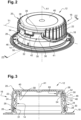
- the cap assembly 12 is shown in more detail in the figures 2 and following. Here it has a threaded neck 14 and a cap 16 designed to be screwed onto the neck 14.
- an axial orientation along the main axis A1 of the cap assembly 12 will be used, without limitation, i.e. along the axis of the neck 14, from bottom to top, considering the Figures 2 and 3 .
- the cap assembly 12 is first described when it occupies its closed position on the neck 14, as shown in the figures 2, 3 And 4 .
- the neck 14 is here provided at its lower axial end with a radial collar 18, or base, which allows the cap assembly 12 to be fixed to the container 10 in a hermetic manner.
- the stopper 16 comprises a stopper body 20 comprising a substantially tubular skirt 22, along the main axis A1.
- the skirt 22 is provided on its internal axial wall with threads 24 which allow it to engage with the neck 14 of the container 10 by screwing.
- the cap 16 also includes a tamper-evident ring 26 which is retained axially on the neck 14 by a retaining rib 28.
- the cap body 20 and the tamper-evident ring 26 are made in a single piece by injection of plastic material into a mold.
- the tamper-evident ring 26 is connected to the skirt 22 by breakable material bridges 29. Unscrewing the cap body 20 relative to the neck 14 causes the material bridges 29 to break to allow the opening of the cap 16 and to give access to the neck 14.
- the tamper-evident ring 26 comprises clamping elements 31 against the neck 14 to slow the rotation of the cap 16 on the neck 14 and to allow it to be held in a determined angular position.
- the tamper-evident ring 26 here comprises, over a portion of its circumference, a connecting portion 30 of generally trapezoidal shape which extends upwards.
- This connecting portion 30 therefore has an axial dimension greater than the axial dimension of the tamper-evident ring 26 over the rest of its circumference.
- the connecting portion 30 extends, on each side of its apex 32, by two connecting arms 34, 36 which are each connected to the cap body 20 by a hinge 38, 39.
- the hinges 38, 39 are here arranged close to the bottom wall 40 of the plug body 20.
- the skirt 22 therefore comprises a notch 41 which generally follows the shape of the connecting portion 30.
- the notch 41 comprises in particular two inclined edges 43, 44, on either side of the connecting portion 30.
- hinges 38, 39 in the form of a thin veil of material to allow the pivoting of the cap body 20 relative to the tamper-evident ring 26, around a transverse pivot axis T1.
- the pivot axis T1 is here generally tangent to the cylinder formed by the skirt 22.
- the two connecting arms 34, 36 delimit between them a notch 42 whose bottom 45 corresponds to the top 32 of the connecting portion 30.
- the cap body 20 comprises a locking finger 46 which is arranged between the two connecting arms 34, 36 and which extends axially towards the tamper-evident ring 26, here downwards.
- the locking finger 46 comprises a free end edge 48 which is here substantially parallel to the pivot axis T1 and which extends in the vicinity of the apex 42, at the bottom of the notch 42, when the cap body 20 is in its closed position.
- the transverse dimension of the locking finger 46 is here slightly less than the transverse dimension of the notch 42.
- the locking finger 46 extends axially in the extension of the connecting portion 30, that is to say that the external axial surface 50 of the locking finger 46 is flush with the connecting portion 30 and with the rest of the skirt 22.
- the upper section of the neck 14 comprises an external peripheral groove 52 which is delimited downwards by a lower rim 54 and upwards by an upper rim 56 intended to cooperate with the locking finger 46 in opening positions of the cap 16, as will be described subsequently.
- the neck 14 comprises at its upper axial end a sealing lip 58 which is designed to be compressed against a sealing element of the cap 16, here an internal axial skirt 60, in the closed position of the cap 16 against the neck 14.
- the sealing lip 58 extends in a generally radial plane, but slightly inclined towards the inside of the neck 14.
- the sealing lip 58 projects slightly towards the inside of the neck 14. the outside of the neck 14, thus forming the upper edge 56 of the outer peripheral groove 52.
- the cap body 20 can be unscrewed by a user. Since the cap body 20 remains connected to the tamper-evident ring by the hinges 38, 39, at the end of the unscrewing the cap body 20 is pivoted about the pivot axis T1 to an intermediate opening position O1, which is illustrated by the figures 5 And 6 .
- the intermediate opening position O1 here corresponds to a pivoting of the cap body 20 by a first angle a1 of between 90 and 100 degrees, preferably 95 degrees, relative to its closed position.
- the cap body 20 is held in the intermediate opening position O1 by the locking finger 46 which pivots with the cap body 20 and which comes to bear by its free end edge 48 against a first bearing zone on the neck 14.
- the first bearing zone is constituted here by the lower edge 54 of the outer peripheral groove 52.
- the plug body 20 is pivoted about the pivot axis T1 to a fully open position O2, which is illustrated by the Figure 7 .
- the fully open position O2 here corresponds to a pivoting of the cap body 20 by a second angle a2 greater than or equal to 150 degrees, preferably substantially equal to 170 degrees, relative to the closed position.
- the cap body 20 is held in the fully open position O2 by the locking finger 46 which comes to bear via the outer axial surface 50 against a second bearing zone on the neck 14.
- the second bearing zone is constituted here by the upper rim 56 of the outer peripheral groove 52.
- it is an end portion of the outer axial surface 50, located in the vicinity of the free end edge 48, which comes to bear against the upper rim 56.
- the stopper body 20 is released from the neck 14 to allow the pouring of a fluid through the opening 15 of the container 10.
- a first radial distance d1 from the pivot axis T1 to the free end edge 48 of the locking finger 46, is slightly greater than a second radial distance d2 to the lower rim 54 of the outer peripheral groove 52.
- cap body 20 is able to pivot in the opposite direction, from each of its opening positions O1, O2 to the closing position.
- the cap 16 and the cap assembly 12 according to the invention allow two indexed opening positions to be available. This allows the cap assembly 12 according to the invention to be implemented in many different container configurations, in particular for brick-shaped containers as in the Figure 1 where it is important to be able to maintain the open position when pouring liquid from the container.
Landscapes
- Engineering & Computer Science (AREA)
- Mechanical Engineering (AREA)
- Closures For Containers (AREA)
Claims (8)
- Kappenanordnung (12), die einen Gewindehals (14), der dazu bestimmt ist, auf einem Behälter (10) montiert zu werden, und eine Kappe (16) für den Behälter (10) aufweist, umfassend:- einen Kappenkörper (20), umfassend eine im Wesentlichen rohrförmige Einfassung (22), die auf einer Hauptachse (A1) zentriert ist, und Mittel für ihren Eingriff mit einem Hals (14), der mit dem Behälter (10) verbunden ist, wobei der Kappenkörper (20) zwischen einer geschlossenen Position und mindestens einer geöffneten Position schwenkbar montiert ist;- einen Originalitätsring (26); und- zwei Verbindungsarme (34, 36), die jeweils auf einer Seite an den Originalitätsring (26) und auf der anderen Seite über ein Scharnier an den Kappenkörper (20) gebunden sind;- wobei der Kappenkörper (20) einen Verriegelungsfinger (46) umfasst, der sich zwischen den zwei Verbindungsarmen (34, 36) befindet und der sich axial in Richtung des Originalitätsrings (26) erstreckt, wenn der Kappenkörper (20) in seiner geschlossenen Position ist;- wobei der Verriegelungsfinger (46) eine freie Endkante (48), die zum Anliegen an einer ersten Anlagezone des Halses (14) vorgesehen ist, um den Kappenkörper (20) in einer geöffneten Zwischenposition (O1) zu halten, und eine äußere axiale Oberfläche (50) umfasst, die zum Anliegen an einer zweiten Anlagezone des Halses (14) vorgesehen ist, um den Kappenkörper (20) in einer vollständig geöffneten Position (O2) zu halten- wobei der obere Abschnitt des Halses (14) eine äußere Umfangsnut (52) aufweist, deren Unterkante (54) die erste Anlagezone ausbildet und deren Oberkante (56) die zweite Anlagezone für die freie Endkante (48) des Verriegelungsfingers (46) ausbildet,dadurch gekennzeichnet, dass:- der Hals (14) an seinem oberen Ende eine Dichtungslippe (58) aufweist, die zum Zusammengedrücktwerden gegen ein Dichtungselement des Kappenkörpers (20) in der geschlossenen Position der Kappe (16) gegen den Hals (14) vorgesehen ist, wobei das äußere radiale Ende der Dichtungslippe (58) die Oberkante (56) der äußeren Umfangsnut (52) ausbildet.
- Kappenanordnung (12) nach dem vorstehenden Anspruch,
dadurch gekennzeichnet, dass die zwei Scharniere (38, 39) eine Schwenkachse (T1) des Kappenkörpers (20) definieren und dass ein erster radialer Abstand (d1) von der Schwenkachse (T1) bis zu der freien Endkante (48) des Verriegelungsfingers (46) etwas größer als ein zweiter radialer Abstand (d2) von der Schwenkachse (T1) bis zu dem Oberteil der Unterkante (54) der äußeren Umfangsnut (52) ist, sodass bei einem Durchgang von der geschlossenen Position in die geöffnete Zwischenposition (O1) des Kappenkörpers (20) der Durchgang des Verriegelungsfingers (46) auf der Unterkante (54) zu einem Druckpunkt in der Schwenkung der Kappe (16) führt. - Kappenanordnung (12) nach einem der Ansprüche 1 oder 2,
dadurch gekennzeichnet, dass der Originalitätsring (26) Spannelemente (31) gegen den Hals (14) zum Bremsen der Drehung der Kappe (16) auf dem Hals (14) aufweist. - Kappenanordnung (12) nach einem der Ansprüche 1 bis 3,
dadurch gekennzeichnet, dass in seiner geöffneten Zwischenposition (O1) der Kappenkörper (20) um einen ersten Winkel (a1) zwischen 90 und 100 Grad, vorzugsweise 95 Grad, relativ zu seiner geschlossenen Position geschwenkt wird. - Kappenanordnung (12) nach einem der Ansprüche 1 bis 4,
dadurch gekennzeichnet, dass in seiner vollständig geöffneten Position (O2) der Kappenkörper (20) um einen zweiten Winkel (a2) größer als oder gleich 150 Grad, vorzugsweise im Wesentlichen gleich 170 Grad, relativ zu seiner geschlossenen Position geschwenkt wird. - Kappenanordnung (12) nach einem der Ansprüche 1 bis 5,
dadurch gekennzeichnet, dass die zwei Verbindungsarme (34, 36) zwischen sich eine im Wesentlichen rechteckige Kerbe (42) begrenzen, und dass in der geschlossenen Position des Kappenkörpers (20) der Verriegelungsfinger (46) in der Kerbe (42) aufgenommen wird. - Kappenanordnung (12) nach dem vorstehenden Anspruch,
dadurch gekennzeichnet, dass die zwei Verbindungsarme (34, 36) an den Originalitätsring (26) durch einen im Wesentlichen trapezförmigen Verbindungsabschnitt (30) gebunden sind, dessen Oberteil (32) den Boden der Kerbe (42) begrenzt. - Quaderförmiger Behälter (10), dadurch gekennzeichnet, dass er mit einer Kappenanordnung (12) nach einem der Ansprüche 1 bis 7 ausgestattet ist.
Applications Claiming Priority (2)
| Application Number | Priority Date | Filing Date | Title |
|---|---|---|---|
| FR2101999A FR3120354B1 (fr) | 2021-03-02 | 2021-03-02 | Bouchon muni d’un doigt de verrouillage |
| PCT/FR2022/050282 WO2022184990A1 (fr) | 2021-03-02 | 2022-02-16 | Bouchon muni d'un doigt de verrouillage |
Publications (3)
| Publication Number | Publication Date |
|---|---|
| EP4301669A1 EP4301669A1 (de) | 2024-01-10 |
| EP4301669C0 EP4301669C0 (de) | 2025-04-02 |
| EP4301669B1 true EP4301669B1 (de) | 2025-04-02 |
Family
ID=75690473
Family Applications (1)
| Application Number | Title | Priority Date | Filing Date |
|---|---|---|---|
| EP22711259.6A Active EP4301669B1 (de) | 2021-03-02 | 2022-02-16 | Kappe mit einem verriegelungsstift |
Country Status (3)
| Country | Link |
|---|---|
| EP (1) | EP4301669B1 (de) |
| FR (1) | FR3120354B1 (de) |
| WO (1) | WO2022184990A1 (de) |
Families Citing this family (1)
| Publication number | Priority date | Publication date | Assignee | Title |
|---|---|---|---|---|
| EP4414282A1 (de) * | 2023-02-09 | 2024-08-14 | Elopak GmbH | Verschlussvorrichtung mit kappe mit vergrösserter innenfläche |
Family Cites Families (2)
| Publication number | Priority date | Publication date | Assignee | Title |
|---|---|---|---|---|
| JP6068899B2 (ja) * | 2012-09-24 | 2017-01-25 | 日本クロージャー株式会社 | 合成樹脂製容器蓋 |
| CN212797893U (zh) * | 2019-05-13 | 2021-03-26 | 赫斯基注塑系统有限公司 | 用于容器的封闭装置和用于通过注射模制形成封闭装置的模具 |
-
2021
- 2021-03-02 FR FR2101999A patent/FR3120354B1/fr active Active
-
2022
- 2022-02-16 WO PCT/FR2022/050282 patent/WO2022184990A1/fr not_active Ceased
- 2022-02-16 EP EP22711259.6A patent/EP4301669B1/de active Active
Also Published As
| Publication number | Publication date |
|---|---|
| EP4301669C0 (de) | 2025-04-02 |
| FR3120354A1 (fr) | 2022-09-09 |
| WO2022184990A1 (fr) | 2022-09-09 |
| EP4301669A1 (de) | 2024-01-10 |
| FR3120354B1 (fr) | 2023-04-14 |
Similar Documents
| Publication | Publication Date | Title |
|---|---|---|
| EP4003866B1 (de) | Sicherheitsverschluss | |
| EP3882172B1 (de) | Kappe für einen behälter mit einem gewindehals, der mit einem blockierorgan durch drücken versehen ist | |
| EP0641721B1 (de) | Schraubkappe mit Originalitäts-Sicherungsband, mit solcher Kappe versehene Verpackung, Verfahren zur Herstellung einer solchen Kappe und solche Verpackung | |
| EP3882173B1 (de) | Scharnierdeckel für einen behälter mit einem hals | |
| FR3094353A1 (fr) | Dispositif de bouchage destine a etre fixe sur un col d’un recipient | |
| FR2804661A1 (fr) | Dispositif de bouchage d'un recipient et recipient pourvu d'un tel dispositif | |
| FR3108317A3 (fr) | Bouchon pour recipient a col filete muni d’un organe de blocage par engagement | |
| FR2729924A1 (fr) | Flacon de distribution de produit | |
| EP4301669B1 (de) | Kappe mit einem verriegelungsstift | |
| EP4026783B1 (de) | Verschlussvorrichtung zur befestigung am hals eines behälters | |
| WO2020182429A1 (fr) | Bouchon pour récipient rigide | |
| FR3106583A1 (fr) | Dispositif de bouchage destiné à être fixé sur le col d’un récipient | |
| EP3889063B1 (de) | Zusammenstellung mit behälter mit gewindehals und kappe mit achsenpositionierungsbeinen und zentrierbeinen | |
| EP4005945B1 (de) | Anordnung mit einem behälter und einer am behälter befestigten verschlussvorrichtung | |
| FR2750954A1 (fr) | Bouchon en matiere synthetique destine a distribuer un liquide contenu dans un recipient, notamment une boisson | |
| EP4353615A1 (de) | Stopfen mit abgeschrägten schlitzen | |
| EP4026782B1 (de) | Verschlussvorrichtung zur befestigung am hals eines behälters | |
| EP3898443A1 (de) | Kappe für starren behälter | |
| FR2707958A1 (fr) | Capsule distributrice en matière plastique pour flacon, tube ou analogue, munie d'un dispositif d'inviolabilité. | |
| EP4147985B1 (de) | Vorrichtung zur lagerung einer flüssigkeit mit einem behälter und einem stopfen, der fest mit dem behälter verbunden bleibt | |
| EP1705129B1 (de) | Plastikkappe | |
| EP0648683A1 (de) | Verschlussvorrichtung für einen mit einem Hals versehenen flaschen- oder topfförmigen Behälter | |
| EP4605314A1 (de) | Kappe mit einer führungsrampe für eine nabe | |
| WO2009056769A1 (fr) | Dispositif de bouchage d'un col de récipient | |
| FR2802182A1 (fr) | Bouchon en matiere synthetique comportant un capuchon articule |
Legal Events
| Date | Code | Title | Description |
|---|---|---|---|
| STAA | Information on the status of an ep patent application or granted ep patent |
Free format text: STATUS: UNKNOWN |
|
| STAA | Information on the status of an ep patent application or granted ep patent |
Free format text: STATUS: THE INTERNATIONAL PUBLICATION HAS BEEN MADE |
|
| PUAI | Public reference made under article 153(3) epc to a published international application that has entered the european phase |
Free format text: ORIGINAL CODE: 0009012 |
|
| STAA | Information on the status of an ep patent application or granted ep patent |
Free format text: STATUS: REQUEST FOR EXAMINATION WAS MADE |
|
| 17P | Request for examination filed |
Effective date: 20230825 |
|
| AK | Designated contracting states |
Kind code of ref document: A1 Designated state(s): AL AT BE BG CH CY CZ DE DK EE ES FI FR GB GR HR HU IE IS IT LI LT LU LV MC MK MT NL NO PL PT RO RS SE SI SK SM TR |
|
| DAV | Request for validation of the european patent (deleted) | ||
| DAX | Request for extension of the european patent (deleted) | ||
| GRAP | Despatch of communication of intention to grant a patent |
Free format text: ORIGINAL CODE: EPIDOSNIGR1 |
|
| STAA | Information on the status of an ep patent application or granted ep patent |
Free format text: STATUS: GRANT OF PATENT IS INTENDED |
|
| INTG | Intention to grant announced |
Effective date: 20241025 |
|
| GRAS | Grant fee paid |
Free format text: ORIGINAL CODE: EPIDOSNIGR3 |
|
| GRAA | (expected) grant |
Free format text: ORIGINAL CODE: 0009210 |
|
| STAA | Information on the status of an ep patent application or granted ep patent |
Free format text: STATUS: THE PATENT HAS BEEN GRANTED |
|
| AK | Designated contracting states |
Kind code of ref document: B1 Designated state(s): AL AT BE BG CH CY CZ DE DK EE ES FI FR GB GR HR HU IE IS IT LI LT LU LV MC MK MT NL NO PL PT RO RS SE SI SK SM TR |
|
| REG | Reference to a national code |
Ref country code: GB Ref legal event code: FG4D Free format text: NOT ENGLISH |
|
| REG | Reference to a national code |
Ref country code: CH Ref legal event code: EP |
|
| REG | Reference to a national code |
Ref country code: IE Ref legal event code: FG4D Free format text: LANGUAGE OF EP DOCUMENT: FRENCH |
|
| REG | Reference to a national code |
Ref country code: DE Ref legal event code: R096 Ref document number: 602022012594 Country of ref document: DE |
|
| U01 | Request for unitary effect filed |
Effective date: 20250410 |
|
| U07 | Unitary effect registered |
Designated state(s): AT BE BG DE DK EE FI FR IT LT LU LV MT NL PT RO SE SI Effective date: 20250417 |
|
| PG25 | Lapsed in a contracting state [announced via postgrant information from national office to epo] |
Ref country code: ES Free format text: LAPSE BECAUSE OF FAILURE TO SUBMIT A TRANSLATION OF THE DESCRIPTION OR TO PAY THE FEE WITHIN THE PRESCRIBED TIME-LIMIT Effective date: 20250402 |
|
| PG25 | Lapsed in a contracting state [announced via postgrant information from national office to epo] |
Ref country code: NO Free format text: LAPSE BECAUSE OF FAILURE TO SUBMIT A TRANSLATION OF THE DESCRIPTION OR TO PAY THE FEE WITHIN THE PRESCRIBED TIME-LIMIT Effective date: 20250702 Ref country code: GR Free format text: LAPSE BECAUSE OF FAILURE TO SUBMIT A TRANSLATION OF THE DESCRIPTION OR TO PAY THE FEE WITHIN THE PRESCRIBED TIME-LIMIT Effective date: 20250703 |
|
| PG25 | Lapsed in a contracting state [announced via postgrant information from national office to epo] |
Ref country code: PL Free format text: LAPSE BECAUSE OF FAILURE TO SUBMIT A TRANSLATION OF THE DESCRIPTION OR TO PAY THE FEE WITHIN THE PRESCRIBED TIME-LIMIT Effective date: 20250402 |
|
| PG25 | Lapsed in a contracting state [announced via postgrant information from national office to epo] |
Ref country code: HR Free format text: LAPSE BECAUSE OF FAILURE TO SUBMIT A TRANSLATION OF THE DESCRIPTION OR TO PAY THE FEE WITHIN THE PRESCRIBED TIME-LIMIT Effective date: 20250402 |
|
| PG25 | Lapsed in a contracting state [announced via postgrant information from national office to epo] |
Ref country code: RS Free format text: LAPSE BECAUSE OF FAILURE TO SUBMIT A TRANSLATION OF THE DESCRIPTION OR TO PAY THE FEE WITHIN THE PRESCRIBED TIME-LIMIT Effective date: 20250702 |
|
| PG25 | Lapsed in a contracting state [announced via postgrant information from national office to epo] |
Ref country code: IS Free format text: LAPSE BECAUSE OF FAILURE TO SUBMIT A TRANSLATION OF THE DESCRIPTION OR TO PAY THE FEE WITHIN THE PRESCRIBED TIME-LIMIT Effective date: 20250802 |
|
| PG25 | Lapsed in a contracting state [announced via postgrant information from national office to epo] |
Ref country code: SM Free format text: LAPSE BECAUSE OF FAILURE TO SUBMIT A TRANSLATION OF THE DESCRIPTION OR TO PAY THE FEE WITHIN THE PRESCRIBED TIME-LIMIT Effective date: 20250402 |
|
| PG25 | Lapsed in a contracting state [announced via postgrant information from national office to epo] |
Ref country code: CZ Free format text: LAPSE BECAUSE OF FAILURE TO SUBMIT A TRANSLATION OF THE DESCRIPTION OR TO PAY THE FEE WITHIN THE PRESCRIBED TIME-LIMIT Effective date: 20250402 |
|
| PG25 | Lapsed in a contracting state [announced via postgrant information from national office to epo] |
Ref country code: SK Free format text: LAPSE BECAUSE OF FAILURE TO SUBMIT A TRANSLATION OF THE DESCRIPTION OR TO PAY THE FEE WITHIN THE PRESCRIBED TIME-LIMIT Effective date: 20250402 |
|
| PLBE | No opposition filed within time limit |
Free format text: ORIGINAL CODE: 0009261 |
|
| STAA | Information on the status of an ep patent application or granted ep patent |
Free format text: STATUS: NO OPPOSITION FILED WITHIN TIME LIMIT |
|
| REG | Reference to a national code |
Ref country code: CH Ref legal event code: L10 Free format text: ST27 STATUS EVENT CODE: U-0-0-L10-L00 (AS PROVIDED BY THE NATIONAL OFFICE) Effective date: 20260211 |
|
| 26N | No opposition filed |
Effective date: 20260105 |
|
| U1N | Appointed representative for the unitary patent procedure changed after the registration of the unitary effect |
Representative=s name: NOVAGRAAF TECHNOLOGIES; FR |
|
| U20 | Renewal fee for the european patent with unitary effect paid |
Year of fee payment: 5 Effective date: 20260225 |