EP4006174B1 - Längliche pelzplatte zur aufnahme eines tierpelzes und deren herstellungsverfahren - Google Patents
Längliche pelzplatte zur aufnahme eines tierpelzes und deren herstellungsverfahren Download PDFInfo
- Publication number
- EP4006174B1 EP4006174B1 EP22151170.2A EP22151170A EP4006174B1 EP 4006174 B1 EP4006174 B1 EP 4006174B1 EP 22151170 A EP22151170 A EP 22151170A EP 4006174 B1 EP4006174 B1 EP 4006174B1
- Authority
- EP
- European Patent Office
- Prior art keywords
- wall element
- pelt board
- pelt
- wall
- edge
- Prior art date
- Legal status (The legal status is an assumption and is not a legal conclusion. Google has not performed a legal analysis and makes no representation as to the accuracy of the status listed.)
- Active
Links
Images


Classifications
-
- C—CHEMISTRY; METALLURGY
- C14—SKINS; HIDES; PELTS; LEATHER
- C14B—MECHANICAL TREATMENT OR PROCESSING OF SKINS, HIDES OR LEATHER IN GENERAL; PELT-SHEARING MACHINES; INTESTINE-SPLITTING MACHINES
- C14B1/00—Manufacture of leather; Machines or devices therefor
- C14B1/58—Drying
-
- C—CHEMISTRY; METALLURGY
- C14—SKINS; HIDES; PELTS; LEATHER
- C14B—MECHANICAL TREATMENT OR PROCESSING OF SKINS, HIDES OR LEATHER IN GENERAL; PELT-SHEARING MACHINES; INTESTINE-SPLITTING MACHINES
- C14B15/00—Mechanical treatment of furs
- C14B15/04—Fur dressing
- C14B15/06—Fur-stretching devices
Definitions
- the present invention relates to a pelt board and a method for drying a pelt.
- the pelts In the drying of pelts, e.g. mink or fox pelt, after skinning and scraping off the layer of fat on the leather side of the pelt, the pelts are typically stretched on a pelt board which is often provided with a fat-absorbing material with the object of removing the remaining fat on the leather side of the pelt.
- the most widespread pelt boards in the past were made of wood, and may in short be described as a flat piece of wood defining a longitudinal direction and having in the longitudinal direction a first broadside surface, a second broadside surface, a first narrow side surface and a second narrow side surface.
- One end of the board, the bottom end is cut off at right angles to the longitudinal direction.
- the lower end adjacent the bottom has a constant breadth, which breadth gradually decreases towards a pointed and rounded end approaching the top end of the board.
- Such boards typically also have a longitudinal slot for allowing air to pass.
- the drying procedure of the pelt shall be understood to be a drying-out of the leather side of the pelt to an extent which by experience prevents any attack on the pelt by mites.
- the drying process is typically effected by the blowing of dry air in the slot on the board via pipes which are introduces into the slot, where via the perforations in the walls of the pelt bag the dry air is diffused out of the leather side of the pelt and dries the pelt.
- a bag shaped holster which is referred to as a fixing bag, which is used for securing the pelts on a pelt board during the drying process.
- the fixing bag is drawn over the board with the stretched pelt from the cranium end of the pelt so that the fur side of the pelt is in tight contact with the fur, which results in the pelt being pressed against the board with a force which is sufficient for the pelt to remain substantially in the stretched position during the drying.
- a pelt board which is lockable in a position, in which it has a first circumference and can also assume a position in which it has a second circumference being smaller than the first circumference by displacing opposing half parts in relation to each other. This results in a considerably easier removal of the pelt from the pelt board.
- US 1,110,016 relates to a pelt board having a pair of longitudinal legs and a nose piece located there between.
- US 3,526,967 relates to a pelt drying system including an air conditioning unit for supplying temperature controlled air to a number of manifolds having nozzles onto which the pelt drying frames are attached.
- WO 82/03634 relates to a pelting board of non-absorbing plastics having a plurality of channels near its edges to supply drying air to the edges of the board so that the pelt dry evenly and stick less often to the board.
- US 3,303,038 relates to a pelt drying frame comprising opposite side rods joined at a nose over which frame a pelt may be drawn and held taut.
- DK 2012 70519 A1 relates to a pelt board has a lower part and an upper part.
- the lower part has an outer cross section circumference which is substantially constant and the upper part has an outer cross section which is gradually decreasing.
- DK 2013 00091 U4 relates to a pelt board has a lower part and an upper part.
- the lower part has an outer cross section circumference, which is substantially constant and the upper part has an outer cross section which is gradually decreasing.
- the lower part extends between 36cm and 50cm.
- DK 177480 B1 discloses a pelt board having two broad elongated side surfaces.
- the pelt board comprises expansion means defining a narrow elongated side surface extending between side edges of the broad side surfaces.
- the expansion means are movable between an expanded position and a non-expanded position.
- Some of the above pelt boards have an outer circumference made up of opposing non-movable surfaces and opposing movable surfaces. Pelt boards having this variable circumference for simplifying the removal of the pelt after drying are thus known in the prior art.
- the pelt boards are thus expanded during the drying process. As the pelt is fixated firmly during drying and may shrink slightly, the pelts may be difficult to remove from the pelt boards. Further, the pelts are typically fixated in a stretched state, thus increasing the pressure of the pelt onto the pelt board. By reducing the circumference of the pelt board, the pelt will be easier to remove from the pelt board.
- the pelt boards used until now only feature a limited variation in the circumference in that only a limited part of the circumferential surfaces are moving/may be reduced.
- the prior art pelt boards have two opposing surfaces which are movable in relation to each other and thus, there may still exist opposing surfaces or parts of the circumference which are non-movable in relation to each other.
- the pelt board according to the prior art may alter the total circumference and thereby relax the pelt, it has been noticed by the applicant that the pelt in some circumstances may still stick quite firm onto the pelt board at the locations of the pelt board at which the surface or circumference has not been reduced.
- the pelt board may be locked in the expanded position and that the movement between the expanded position and the reduced position may be performed very accurately using very little force.
- the pelt board may be modified to accommodate pelts of different sizes and shapes.
- an elongated pelt board for accommodating an animal pelt, the pelt board defining a longitudinal direction, a first radial direction perpendicular to the longitudinal direction and a second radial direction perpendicular to the longitudinal direction and the first radial direction, the pelt board comprising:
- an elongated pelt board for accommodating an animal pelt, the pelt board defining a longitudinal direction, a first radial direction perpendicular to the longitudinal direction and a second radial direction perpendicular to the longitudinal direction and the first radial direction, the pelt board comprising:
- the pelt board should have an overall size which is suitable for accommodating a pelt of an animal such as a mink or fox.
- the pelt board typically has a substantially elliptic cylindrical shape which is tapering in the longitudinal direction.
- the pelt is applied onto the pelt board by drawing in onto the pelt board in the longitudinal direction, while the pelt board assumes its expanded state.
- state of the art pelt bags may be used between the pelt and the pelt board in order to remove fatty substances from the pelt.
- the wall elements may be arched, which in connection with the wall elements should be understood to mean that the outer surfaces of the respective wall elements of the pelt board have a convex shape.
- the wall elements typically include a large number of holes or nozzles for allowing ventilation air to pass from the cavity within the pelt board to the outside through the pelt.
- the first, second, third and fourth wall elements together define the substantially elliptical outer circumference of the pelt board, which is suitable for and adapted for accommodating a pelt of an animal, through its respective outwardly oriented surfaces.
- the inwardly oriented surfaces may preferably define a concave shape, which surfaces together define the cavity in the pelt board.
- the wall elements are typically made of plastics. The wall elements are further delimited in the circumferential direction by longitudinal edges.
- the elongated core element which is located in the cavity, is movable in the longitudinal direction in relation to the wall elements.
- the actuator members of the wall elements and the cooperating members of the core element interact when the core element is moved in the longitudinal direction within the cavity.
- the cooperating members move in the longitudinal direction together with the elongated core whereas the actuator members move in any of the radial directions along with its respective wall element.
- the interaction between the cooperating members and the actuator members translate the longitudinal movement of the cooperating members to a radial movement of the actuator members.
- the actuator members and the cooperating members thus cause the wall elements to move towards each other or away from each other in the respective first or second radial direction, thus making the cavity smaller or larger, when the core element is moved in the longitudinal direction relative to the wall elements.
- the wall elements are thus movable between the contacted state, in which the wall elements have moved towards each other, reducing the radial distances, and consequently the circumference of the pelt board and the cavity is small, and an expanded state in which the wall elements have moved away from each other, increasing the radial distances and consequently the circumference of the pelt board and the cavity is large.
- an upward movement of the elongated core element in relation to the wall elements yields an expansion of the circumference of the pelt board
- a downward movement of the elongated core element in relation to the wall elements yields a contraction of the circumference of the pelt board
- the wall elements of the pelt move in directions which are spaced apart by 90 degrees and thus realize a four way expansion and contraction of the pelt board.
- the radial directions are perpendicular, i.e. spaced apart by 90 degrees.
- the overall impression of the shape of the pelt board i.e. the general circumferential profile, is at least largely unaffected by the movements of the wall elements.
- the outwardly oriented pressure on the pelt during the drying will be applied substantially uniformly in the pelt by the outer surfaces of the arched elements.
- the outer surface of the wall elements will constitute the contacts surface between the pelt and the pelt board, not taking into account the optional presence of a pelt bag between the pelt and the pelt board.
- Using a two way expansion and contraction, e.g. by opposing movable wall element, will necessarily apply more pressure on the pelt at the movable surfaces relative to the non-movable surfaces. Such non-uniformly applied pressure may lead to non-uniform pelts or even damages on the pelt.
- the circumference of the pelt board is large.
- the pelt is applied to the pelt board, optionally using a pelt bag.
- the pelt looses fat and moist and consequently contracts slightly. It may thereafter be very difficult to remove the pelt from the board.
- the circumference of the pelt board defined by the outer surface of the wall elements will be smaller and thus typically allow the pelt to loosen from the outer surfaces of the wall elements, such that the pelt may be removed from the pelt board.
- the complete circumference of the pelt board will contract, effectively eliminating the risk of the pelt sticking to the pelt board.
- the first and second sets of oppositely located longitudinal edges overlap respective edges of the third and fourth sets of oppositely located longitudinal edges or alternatively the third and fourth sets of oppositely located longitudinal edges overlapping respective edges of the first and second sets of oppositely located longitudinal edges, and, when in the expanded state the first and second sets of oppositely located longitudinal edges are substantially flush with respective edges of the third and fourth sets of oppositely located longitudinal edges.
- the outer surfaces of the wall elements should be at least substantially continuous.
- the longitudinal edges of the wall elements in the expanded state should be at least substantially flush. This means that the outer surfaces of the wall elements form a substantially continuous structure avoiding any large gaps between the wall elements and adjacent outer surfaces.
- the longitudinal edges of adjacent wall elements of the pelt board do overlap each other such that only a minor deviation from a continuous surface exists between adjacent outer surfaces of the wall elements. It is understood from the above that in order to realize the contraction, a part of the wall elements located at the respective longitudinal edges of the wall element may be pushed above or below its adjacent wall elements to form the overlapping such that the longitudinal edges are non-flush.
- any of the first wall element, the second wall element, the third wall element and/or the fourth wall element define a central part and a peripheral part, the peripheral part encompassing the set of edges, the central part and the peripheral part being flexibly joined together and when the first wall element, the second wall element, the third wall element and the fourth wall element define the contracted state, the peripheral part assuming an inwardly oriented position, whereas when the first wall element, the second wall element, the third wall element and the fourth wall element define the expanded state, the peripheral part assuming an outwardly oriented position.
- the wall elements may be partially flexible.
- the thickness of the wall element will typically prevent a fully flush outwardly oriented surface in the expanded state.
- the central part of the respective wall element is movable in the respective first radial direction or the second radial direction according to the movement of the corresponding wall element, whereas the peripheral part may be movable in both the first and the second radial direction in order to be accommodated above or below the adjacent wall element as described above.
- the first actuator member and the second actuator member constitute pins and the first cooperating member and the second cooperating member constitute grooves, e.g. linear or curved grooves, in which the pins are guided between the contracted state and the expanded state, or, wherein the first cooperating member and the second cooperating member constitute pins and the first actuator member and the second actuator member constitute grooves, e.g. linear or curved grooves, in which the pins are guided between the contracted state and the expanded state.
- first actuator member and the second actuator member constitute grooves, e.g. linear or curved grooves
- first cooperating member and the second cooperating member constitute pins which are guided by the grooves between the contracted state and the expanded state, or any combination thereof.
- the longitudinal movement of the elongated core thus translates into a radial movement of the wall elements.
- the groove/pin configuration also allows for a very convenient latching of the wall elements and the core.
- the third actuator member and the fourth actuator member constitute wedge members for contacting the third cooperating member and the fourth cooperating member, or, the third cooperating member and the fourth cooperating member constitute wedge members for contacting the third actuator member and the fourth actuator member.
- Another guiding principle is employed by using wedge members which exhibit an angle and may consequently slide outwardly when pushed.
- the longitudinal movement of the elongated core element thus translates into a radial movement by interaction between the sloped members.
- This guiding principle may preferably be used when changing from said contracted state to said expanded state.
- the third actuator member and the fourth actuator members further engage the cooperating members opposite the elongated core element.
- Yet another guiding principle is employed by using actuator members acting on the side of the elongated core element which is located opposite the wall element to be moved.
- the longitudinal movement of the elongated core element thus translates into a radial movement by interaction typically by using sloped members.
- This guiding principle may preferably be used when changing from said expanded state to said contracted state.
- any of the first wall element, second wall element, third wall element and fourth wall element have an arched shape such that any of said first outwardly oriented surface, second outwardly oriented surface, third outwardly oriented surface and fourth outwardly oriented surface define a convex shape.
- Ventilation grooves may be present in order to allow dry air to be injected into the pelt for removing any remaining moisture in the pelt and thereby decrease the drying time of the pelt.
- the first wall element, the second wall element, the third wall element and the fourth wall element define an opening between the cavity and the outside of the pelt board at the bottom end for allowing ventilation air to enter the cavity.
- the dry air injected into the pelt via the pelt board and used for decreasing the drying time of the pelt may be let into the pelt board via a cavity near the bottom end of the pelt board.
- the bottom end of the pelt board is typically attachable to a drying unit for holding the pelt board in an upright position and for supplying the drying air.
- the third wall element and the fourth wall element are fixedly connected at the bottom end.
- the pelt board may assume the same circumference at the bottom end both in the expanded state and in the contracted state. This may be made by fixedly connecting the wall elements at constant distance relative to each other near the bottom end and allowing the flexibility of the wall elements to determine the movement of the lower portion of the pelt board.
- the lower extreme of the pelt board is typically not used for accommodating the pelt since the pelt boards are typically made longer than the longest pelts for which the pelt boards are intended.
- the first wall element defines a first radial edge adjacent the top end of the elongated core
- the second wall element comprising a second radial edge adjacent the top edge of the elongated core
- the pelt board further comprising:
- the pelt board which is expandable along its entire circumference may be undesirable near the upper part of the pelt board.
- the upper part of the pelt board is intended to accommodate the neck and head part of the animal and since the neck and head part of the animal pelt have a smaller circumference than the body part of the pelt, the pelt board usually is tapered towards the top end having a thickness of the pelt board which is reduced near the top of the pelt board, as described above. Since the actuator members, cooperating members and elongated core element require some space within the cavity, it may not be feasible to allow the pelt board to expand and contract along its entire circumference, i.e. a four way expansion of the pelt board as described above, at the top end of the board. Instead, at the top end of the board, the pelt board may be allowed to be movable in only two opposing directions.
- the fifth wall element constitutes an extension of the first wall element
- the sixth wall element constitutes an extension of the second wall element
- the core extension element constitutes and extension of the elongated core element.
- the moving principle in the first radial direction of the fifth wall element, sixth wall element and core extension element may be the same between the first wall element, the second wall element and the elongated core element, albeit the adjacent wall elements moving in the second radial direction are missing.
- This top structure including the fifth wall element and the sixth wall element may thus be made significantly thinner than the bottom structure including the first wall element, the second wall element, the third wall element, the fourth wall element.
- the fifth wall element and the sixth wall element may optionally be arched but will typically be substantially flat due to the limited space available at the top of the pelt board.
- the third wall element and the fourth wall element comprise opposing extension elements partially enclosing the core extension element.
- the top structure may include opposing extension elements which limit the radial movement or flexibility of the core extension element.
- the core extension element is thus located between the opposing extension elements, which are fixated to the respective third wall element and the fourth wall element.
- the pelt board comprises:
- the substantially elliptic cylindrical elements may be used for extending a short pelt board and make it suitable for larger animals.
- the substantially elliptic cylindrical elements typically do not have any variable circumference, however, the pelt typically sticks to the pelt board near the top and bottom ends of the pelt board , thus the elliptic cylindrical elements merely constitutes spacers. This will have the advantage that the same pelt board may be used with animals of very different size and the adaptation to the size of the particular animal will be made by using the elliptic cylindrical elements.
- the core connecting element is merely used for connecting the longitudinal motion from the elongated core element to the core extension element.
- the fifth cooperating member and the sixth cooperating member constitute pins and the fifth actuator member and the sixth actuator member constitute grooves, e.g. linear or curved grooves, in which the pins are guided between the contracted state and the expanded state, or, the fifth actuator member and the sixth actuator member constitute pins and the fifth cooperating member and the sixth cooperating member constitute grooves, e.g. linear or curved grooves, in which the pins are guided between the contracted state and the expanded state
- the fifth wall element is connected to the first wall element at the first radial edge and the sixth wall element is connected to the second wall element at the second radial edge.
- the elongated core element comprises a first protrusion adjacent the bottom end, the elongated core element being spring-loaded at the bottom end and defining a centralized relaxed position and a non-centralized loaded position in the first radial direction and/or second radial direction
- the first wall element, the second wall element, the third wall element or the fourth wall element comprise a second protrusion cooperating with the first protrusion such that when the first wall element, the second wall element, the third wall element and the fourth wall element define the expanded state and the elongated core element defines the centralized related position, the first and second protrusions prevent any longitudinal movement of the elongated core element, whereas when the elongated core element defines the non-centralized loaded position, the first and second protrusions allow longitudinal movement of the elongated core element.
- the pelt board is maintained in the expanded state merely due to the design of and internal friction between the movable parts of the pelt board.
- the friction increases with the pressure applied to the pelt board and although an increased friction may help keeping the pelt board in the expanded state also when a large inwardly pressure is applied from the pelt, it may also be very difficult to contract the pelt board.
- Experience has shown that after the drying, when the pelt has shrunk and thus applies a large pressure onto the pelt board, the users have to apply a large manual force to cause the pelt board to collapse. This work is very tedious and may lead to work related injuries.
- the locking mechanism described above making use of cooperating protrusions for preventing movement of the elongated core element and thereby contraction of the pelt board allows the pelt board to remain in the expanded state even when exposed to very large inwardly oriented pressure, while reducing the amount of work needed for changing the pelt board into the contracted state.
- the first and second protrusions will interlock when the elongated core is in its central position, effectively preventing any longitudinal movement of the elongated core, which in turn prevents any radial movement of the wall elements.
- the inwardly oriented pressure from the dried pelt will cause the wall element to move inwardly and the pelt board to contact, while the elongated core element is moved in the longitudinal direction and the first protrusion is passing by the second protrusion.
- This mechanism will also be less prone to accidental activation since it is not depending on any hard to determine internal friction between the activation members and the cooperating members.
- Such pelt board may e.g. be defined as an elongated pelt board for accommodating an animal pelt, the pelt board defining a longitudinal direction, a first radial direction perpendicular to the longitudinal direction and a second radial direction perpendicular to the longitudinal direction and the first radial direction, the pelt board having a wall element and an elongated core element covered by the wall element, the wall element being capable of assuming an expanded state and a contacted state by longitudinal movement of the elongated core element, the elongated core element comprising a first protrusion adjacent a bottom end of the pelt board, the core element being spring-loaded at the bottom end and defines a centralized relaxed position and a non-centralized loaded position in the first radial direction and/or second radial direction, the wall element comprising a second protrusion cooperating with the first protrusion
- the change from expanded state to contracted state may preferably be made when the bottom end of the elongated core element is attached to the drying unit, e.g. by tilting the pelt board sideways, thereby also taking advantage of the leverage provided by the pelt board for overcoming the friction between the first and second protrusions.
- the pelt board is adapted to establish an intermediate position in which the first wall element and the second wall element, or alternatively, the third wall element and the fourth wall element, are shifted relative to one another for establishing a first intermediate state and a second intermediate state, respectively.
- the first wall element, the second wall element, the third wall element and the fourth wall element further define a first intermediate state in which the first radial distance between the first inwardly orientated surface and the second inwardly orientated surface is increased, as compared to the contracted state.
- the first wall element, the second wall element, the third wall element and the fourth wall element further define a second intermediate state, in which the second radial distance between the third inwardly orientated surface and the fourth inwardly orientated surface is increased, as compared to the contracted state.
- the elongated pelt board may, according to the above described two alternative embodiments, in which a first and a second intermediate state, respectively, are defined, the elongated pelt board may be adapted to allow the change from the contracted state to the expanded state and vice versa via the first intermediate state, or alternatively via the second intermediate state, or by directly shifting the elongated pelt board from the contracted state to the expanded state or in the alternative, when collapsing the elongated pelt board from the expanded state to the contracted state.
- the first and second wall elements and likewise the third and fourth wall elements are integrated into integral wall element structures and consequently, according to this alternative embodiment, the first wall element defines a first edge among the first set of oppositely located longitudinal edges and the second wall element defines a second edge among the second set of oppositely located longitudinal edges, the first and second edges being positioned adjacent one another, and the first wall element and the second wall element being integrally connected along the first and second edges, and the third wall element defines a third edge among the third set of oppositely located longitudinal edges, and the fourth wall element defines a fourth edge among the fourth set of oppositely located longitudinal edges, the third and fourth edges being positioned adjacent one another, and the third wall element and the fourth wall element being integrally connected along said third and fourth edges.
- the first actuator member and the second actuator member are constituted by a single first integral actuator member
- the third actuator member and said fourth actuator member are constituted by a single second integral actuator member
- an elongated pelt board for accommodating an animal pelt, the pelt board defining a longitudinal direction, a first radial direction perpendicular to the longitudinal direction and a second radial direction perpendicular to the longitudinal direction and the first radial direction, the pelt board comprising:
- the pelt board according to the first aspect of the present invention should have an overall size which is suitable for accommodating a pelt of an animal such as a mink or fox.
- the pelt board according to the first aspect of the present invention typically has a substantially elliptic cylindrical shape which is tapering in the longitudinal direction.
- the pelt is applied onto the pelt board according to the first aspect of the present invention by drawing in onto the pelt board according to the first aspect of the present invention in the longitudinal direction, while the pelt board according to the first aspect of the present invention assumes its expanded state.
- state of the art pelt bags may be used between the pelt and the pelt board according to the firstaspect of the present invention in order to remove fatty substances from the pelt.
- the wall elements typically include a large number of holes or nozzles for allowing ventilation air to pass from the cavity within the pelt board according to the first aspect of the present invention to the outside through the pelt.
- the first and second wall elements together define the substantially elliptical outer circumference of the pelt board according to the first aspect of the present invention, which is suitable for and adapted for accommodating a pelt of an animal, through its respective outwardly oriented surfaces.
- the inwardly oriented surfaces may preferably define a concave shape, which surfaces together define the cavity in the pelt board according to the first aspect of the present invention.
- the wall elements are typically made of plastics.
- the wall elements are further delimited in the circumferential direction by longitudinal edges.
- the elongated core element which is located in the cavity, is movable in the longitudinal direction in relation to the wall elements.
- the actuator members of the wall elements and the cooperating members of the core element interact when the core element is moved in the longitudinal direction within the cavity.
- the cooperating members move in the longitudinal direction together with the elongated core whereas the actuator members move in any of the radial directions along with its respective wall element.
- the interaction between the cooperating members and the actuator members translate the longitudinal movement of the cooperating members to a radial movement of the actuator members.
- the actuator members and the cooperating members thus cause the wall elements to move towards each other or away from each other in the respective first or second radial direction, thus making the cavity smaller or larger, when the core element is moved in the longitudinal direction relative to the wall elements.
- the wall elements are thus movable between the contacted state, in which the wall elements have moved towards each other, reducing the radial distances, and consequently the circumference of the pelt board according to the first aspect of the present invention and the cavity is small, and an expanded state in which the wall elements have moved away from each other, increasing the radial distances and consequently the circumference of the pelt board according to the first aspect of the present invention and the cavity is large.
- an upward movement of the elongated core element in relation to the wall elements yields an expansion of the circumference of the pelt board according to the first aspect of the present invention
- a downward movement of the elongated core element in relation to the wall elements yields a contraction of the circumference of the pelt board according to the first aspect of the present invention
- the outer surface of the wall elements will constitute the contacts surface between the pelt and the pelt board according to the first aspect of the present invention, not taking into account the optional presence of a pelt bag between the pelt and the pelt board according to the first aspect of the present invention.
- the circumference of the pelt board according to the first aspect of the present invention is large.
- the pelt is applied to the pelt board according to the first aspect of the present invention, optionally using a pelt bag.
- the pelt looses fat and moist and consequently contracts slightly. It may thereafter be very difficult to remove the pelt from the board.
- the circumference of the pelt board according to the first aspect of the present invention defined by the outer surface of the wall elements will be smaller and thus allow the pelt to loosen from the outer surfaces of the wall elements, such that the pelt may be removed from the pelt board according to the first aspect of the present invention.
- the complete circumference of the pelt board according to the first aspect of the present invention will contract, effectively eliminating the risk of the pelt sticking to the pelt board according to the first aspect of the present invention.
- the wall elements may be partially flexible.
- the thickness of the wall element will typically prevent a fully flush outwardly oriented surface in the expanded state.
- the first actuator member and the second actuator member constitute pins and the first cooperating member and the second cooperating member constitute grooves, e.g. linear or curved grooves, in which the pins are guided between the contracted state and the expanded state, or, wherein the first cooperating member and the second cooperating member constitute pins and the first actuator member and the second actuator member constitute grooves, e.g. linear or curved grooves, in which the pins are guided between the contracted state and the expanded state.
- first actuator member and the second actuator member constitute grooves, e.g. linear or curved grooves
- first cooperating member and the second cooperating member constitute pins which are guided by the grooves between the contracted state and the expanded state, or any combination thereof.
- the longitudinal movement of the elongated core thus translates into a radial movement of the wall elements.
- the groove/pin configuration also allows for a very convenient latching of the wall elements and the core.
- Another guiding principle is employed by using wedge members which exhibit an angle and may consequently slide outwardly when pushed.
- the longitudinal movement of the elongated core element thus translates into a radial movement by interaction between the sloped members.
- This guiding principle may preferably be used when changing from said contracted state to said expanded state.
- Yet another guiding principle is employed by using actuator members acting on the side of the elongated core element which is located opposite the wall element to be moved.
- the longitudinal movement of the elongated core element thus translates into a radial movement by interaction typically by using sloped members.
- This guiding principle may preferably be used when changing from said expanded state to said contracted state.
- the first wall element and the second wall element have an arched shape such that the first outwardly oriented surface and the second outwardly oriented surface define a convex shape.
- Using a convex shape of the wall element will allow the outer surfaces of the wall elements to adapt to the pelt which typically has a cylindrical shape.
- the first wall element and the second wall element comprise ventilation grooves between the cavity and the outside of the pelt board according to the third and fourth aspects of the present invention.
- Ventilation grooves may be present in order to allow dry air to be injected into the pelt for removing any remaining moisture in the pelt and thereby decrease the drying time of the pelt.
- the first wall element and the second wall element define an opening between the cavity and the outside of the pelt board according to the third and fourth aspects of the present invention at the bottom end for allowing ventilation air to enter the cavity.
- the dry air injected into the pelt via the pelt board according to the first aspect of the present invention and used for decreasing the drying time of the pelt may be let into the pelt board according to the first aspect of the present invention via a cavity near the bottom end of the pelt board according to the first aspect of the present invention.
- the bottom end of the pelt board according to the first aspect of the present invention is typically attachable to a drying unit for holding the pelt board according to the third and fourth aspects of the present invention in an upright position and for supplying the drying air.
- the first wall element and the third wall element are constituted by a first unitary structure
- the second wall element and the fourth wall element are constituted by a second unitary structure
- the core element and the core extension element are constituted by a second unitary core element structure.
- the pelt board may assume the same circumference at the bottom end both in the expanded state and in the contracted state. This may be made by fixedly connecting the wall elements at constant distance relative to each other near the bottom end and allowing the flexibility of the wall elements to determine the movement of the lower portion of the pelt board.
- the lower extreme of the pelt board is typically not used for accommodating the pelt since the pelt board according to the third and fourth aspects of the present invention is typically made longer than the longest pelts for which the pelt board according to the third and fourth aspects of the present invention is intended.
- the first wall element defines a first radial edge adjacent the top end of the elongated core, the second wall element comprising a second radial edge adjacent the top edge of the elongated core, the pelt board further comprising:
- pelt board which is expandable along its entire circumference may be undesirable near the upper part of the pelt.
- the upper part of the pelt board is intended to accommodate the neck and head part of the animal and since the neck and head part of the animal pelt have a smaller circumference than the body part of the pelt, the pelt board usually is tapered towards the top end having a thickness of the pelt board which is reduced near the top of the pelt board, as described above. Since the actuator members, cooperating members and elongated core element require some space within the cavity, it may not be feasible to allow the pelt board to expand and contract along its entire circumference, at the top end of the board.
- the third wall element and the fourth wall element comprise opposing extension elements partially enclosing the core extension element.
- the pelt board comprises:
- the third cooperating member and the fourth cooperating member constitute pins and the third actuator member and the fourth actuator member constitute grooves, e.g. linear or curved grooves, in which the pins are guided between the contracted state and the expanded state, or, the third actuator member and the fourth actuator member constitute pins and the third cooperating member and the fourth cooperating member constitute grooves, e.g. linear or curved grooves, in which the pins are guided between the contracted state and the expanded state.
- the third wall element is connected to the first wall element at the first radial edge and the fourth wall element is connected to the second wall element at the second radial edge.
- the elongated core element comprises a first protrusion adjacent the bottom end, the elongated core element being spring-loaded at the bottom end and defining a centralized relaxed position and a non-centralized loaded position in the first radial direction and/or second radial direction
- the first wall element and the second wall element comprise a second protrusion cooperating with the first protrusion such that when the first wall element and the second wall element define the expanded state and the elongated core element defines the centralized related position, the first and second protrusions prevent any longitudinal movement of the elongated core element, whereas when the elongated core element defines the non-centralized loaded position, the first and second protrusions allow longitudinal movement of the elongated core element.
- the pelt board according to the invention is maintained in the expanded state merely due to the design of and internal friction between the movable parts of the pelt board.
- the friction increases with the pressure applied to the pelt board and although an increased friction may help keeping the pelt board in the expanded state also when a large inwardly pressure is applied from the pelt, it may also be very difficult to contract the pelt board.
- Experience has shown that after the drying, when the pelt has shrunk and thus applies a large pressure onto the pelt board, the users have to apply a large manual force to cause the pelt board to collapse. This work is very tedious and may lead to work related injuries.
- the locking mechanism described above making use of cooperating protrusions for preventing movement of the elongated core element and thereby contraction of the pelt board allows the pelt board to remain in the expanded state even when exposed to very large inwardly oriented pressure, while reducing the amount of work needed for changing the pelt board into the contracted state.
- the first and second protrusions will interlock when the elongated core is in its central position, effectively preventing any longitudinal movement of the elongated core, which in turn prevents any radial movement of the wall elements.
- the inwardly oriented pressure from the dried pelt will cause the wall element to move inwardly and the pelt board to contact, while the elongated core element is moved in the longitudinal direction and the first protrusion is passing by the second protrusion.
- This mechanism will also be less prone to accidental activation since it is not depending on any hard to determine internal friction between the activation members and the cooperating members.
- Such pelt board may e.g. be defined as an elongated pelt board for accommodating an animal pelt, the pelt board defining a longitudinal direction, a first radial direction perpendicular to the longitudinal direction and a second radial direction perpendicular to the longitudinal direction and the first radial direction, the pelt board having a wall element and an elongated core element covered by the wall element, the wall element being capable of assuming an expanded state and a contacted state by longitudinal movement of the elongated core element, the elongated core element comprising a first protrusion adjacent a bottom end of the pelt board, the core element being spring-loaded at the bottom end and defines a centralized relaxed position and a non-centralized loaded position in the first radial direction and/or second radial direction, the wall element comprising a second protrusion cooperating with the first protrusion
- the change from expanded state to contracted state may preferably be made when the bottom end of the elongated core element is attached to the drying unit, e.g. by tilting the pelt board sideways, thereby also taking advantage of the leverage provided by the pelt board for overcoming the friction between the first and second protrusions.
- the above method according to invention may preferably be used together with the pelt board according to the first aspect.
- the wall elements and the elongated core are preferably made as separate molded plastic items.
- the wall elements are typically snap fitted together.
- any of the first wall element, the second wall element, the third wall element and the fourth wall element may constitute two or more items which are snap fitted together.
- a system for drying a pelt comprising a drying unit and a pelt board, said pelt having a substantially tubular shape defining an inwardly oriented leather side and an outwardly oriented fur side and further defining a nose end and a rear end,
- the overall configuration and in particular the apertured outer surface of the pelt board also establishes a limitation as to the air inlet capability or volumetric air inlet capability of the prior art pelt boards.
- the air outlet from the drying unit and the air inlet into the pelt board which drying unit and pelt board constitute a system, exhibit a large interface area allowing a substantive increase of the air inlet into the pelt board, which again improves the drying capability or reduces the drying time for the drying of the pelts mounted on the pelt boards.
- the air inlet area and the air outlet area are of the same size or alternatively of substantially the same size, simply for gaining the benefit of the large inlet area of the pelt board.
- an increase of the inlet area above approximately 45-50% of the bottom area provides a rather limited increase in the drying capability of the pelt board and the overall system, as it is contemplated that the dominating factor in determining the maximum drying capability and the maximum volume of air, which may be forced into the drying pelt, is in an embodiment in which the inlet air exceeds 50% of the bottom area predominantly determined or limited by the apertured wall of the pelt board.
- the air inlet of the pelt board may be constituted by a single large aperture at the bottom of the pelt board or alternatively be implemented by several individual air inlets, which are preferably located circumferentially encircling the connector of the pelt board simply for increasing the flow of air into the pelt board along the central axis of the pelt board.
- the air outlet of the drying unit may advantageously in accordance with and in conformity with the above embodiment of the pelt board be located circumferentially encircling the receptor aperture.
- the connector may have additional inlet slots for allowing air to be introduced into the inner cavity from the housing of the drying unit through the slots, which additional slots evidently further increase the volumetric input of air into the pelt board.
- two adaptors are provided, the one serving for allowing a conventional drying unit to be used in combination with the drying unit of the system, and the alternative or second embodiment constituting an adaptor allowing the pelt board of the system according to the ninth aspect of the present invention to be used in combination with the conventional drying unit to be used in combination with the conventional or prior art pelt board such as the above described pelt boards produced by the applicant company and the competitor company Jasopels A/S.
- the system further comprises a first adaptor having an inlet end configured in conformity with said bottom end of said pelt board and having an opposite closed-off upper end, in which a minor air outlet aperture, such as an aperture of the size of 400mm 2 , is provided for allowing air to be output through said minor air outlet aperture for input into a conventional pelt board having a smaller size connector through which air is input into the inner cavity of the pelt board through the connector, said first adaptor having a first inner air passage from said air inlet to said minor air outlet aperture, and still further comprises a second adaptor having an outlet configured in conformity with said bottom end of said pelt board and having an opposite closed-off bottom end, from which a smaller size connector extends, said smaller size connector having inlet slots for allowing air to be introduced into the inner space of said second adaptor through said smaller size connector, said second adaptor having a second inner air passage from said small size connector to said air outlet.
- a minor air outlet aperture such as an aperture of the size of 400mm 2
- the drying unit is advantageously embodied for receiving a plurality of pelt boards and the system consequently further, according to the presently preferred embodiment of the system comprises a set of pelt boards and a housing of the drying unit, and similarly has a plurality of receptor apertures and air outlets.
- the drying unit preferably has biased closing-off plates for closing off receptor apertures and corresponding air outlets, in which receptor apertures no pelt board is received, simply to prevent that the air forced into the housing of the drying unit is outlet through open receptor apertures and corresponding air outlets without being introduced into the pelt boards, on which pelts are mounted and consequently being wasted in relation to the intentional purpose of forcing air into the housing of the drying unit, namely of causing the air to be outlet from the housing of the drying unit and input into the pelt boards, on which pelts are received.
- system and particularly the pelt board of the system may be implemented in relating to the advantageous embodiments of the expandable and collapsible pelt boards.
- a drying unit for use in combination with a pelt board and for drying a pelt, said pelt having a substantially tubular shape defining an inwardly oriented leather side and an outwardly oriented fur side and further defining a nose end and a rear end,
- the drying unit may advantageously include any of the features of the above described system.
- a pelt board for use in combination with a drying unit for drying a pelt said pelt having a substantially tubular shape defining an inwardly oriented leather side and an outwardly oriented fur side and further defining a nose end and a rear end,
- the pelt board may, apart from any of the features of the pelt board defined in the system, preferably and advantageously include features according to the above described aspects relating to the expandable and collapsible pelt boards.
- an adaptor for use in combination with a drying unit for drying a pelt, and a pelt board said pelt having a substantially tubular shape defining an inwardly oriented leather side and an outwardly oriented fur side and further defining a nose end and a rear end, said pelt board and said drying unit defining an air transfer area between the bottom end of said pelt board and an air outlet of said drying unit constituting between 15% and 95% of the bottom end area of said pelt board, such as preferably more than 30%, such as preferably 45-50% of said bottom area of said pelt board, said adaptor having an inlet end configured in conformity with said bottom end of said pelt board and having an opposite closed-off upper end, in which a minor air outlet aperture, such as an
- an adaptor for use in combination with a drying unit for drying a pelt, and a pelt board said pelt having a substantially tubular shape defining an inwardly oriented leather side and an outwardly oriented fur side and further defining a nose end and a rear end, said pelt board having a smaller size connector at its bottom end, through which smaller size connector air is input into the inner cavity of the pelt board, and said drying unit having a minor receptor and air outlet aperture for receiving said smaller size connector, such as an aperture of the size of 400mm 2
- said adaptor having an inlet end including said smaller size connector and having an opposite upper end, in which an air outlet aperture of the size of 1000mm 2 -2500mm 2 is provided for allowing air to be output through said air outlet aperture for input into
- a system for drying a pelt comprising a drying unit and a pelt board, said pelt having a substantially tubular shape defining an inwardly oriented leather side and an outwardly oriented fur side and further defining a nose end and a rear end,
- a drying unit for use in combination with a pelt board and for drying a pelt, said pelt having a substantially tubular shape defining an inwardly oriented leather side and an outwardly oriented fur side and further defining a nose end and a rear end,
- a drying unit for use in combination with a pelt board and for drying a pelt having a substantially tubular shape defining an inwardly oriented leather side and an outwardly oriented fur side and further defining a nose end and a rear end,
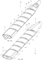
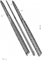
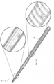
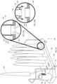
- FIG. 1A shows a perspective view of a first embodiment of a pelt board 10 in the contracted state.
- the pelt board 10 comprises a lower part 12 and an upper part 14.
- the lower part 12 comprises a first arched wall element 16, a second wall element 18, a third wall element 20, a fourth wall element 22 which together define a cavity 24 in which an elongated core element 26 is located.
- the first arched wall element 16, the second wall element 18, the third wall element 20 and the fourth wall element 22 are shown here schematically as being solid, it is however understood that for optimal drying of the pelt, they should be louvered for allowing ventilation air to pass from the pelt board to the pelt.
- the upper part 14 comprise a fifth wall element 28 and a sixth wall element 30, both which in the present case are arched and tapered but which also may be made non-arched and non-tapered.
- the elongated core element 26 extends into the upper part 14 in the form of a core extension element 26'.
- the first wall element 16 and the second wall element 18 comprises respective peripheral elements 16' 16" 18' 18", which are flexibly connected to the center elements of the respective first wall element 16 and the second wall element 18.
- the third wall element 20 will in the present contracted state overlap the peripheral elements 16' 18' and the fourth wall element 20 will in the present contracted state overlap the peripheral elements 16" 18".
- the fifth wall element 28 and a sixth wall element 30 both mutually overlap each other.
- An extension element 32 is interconnecting the lower part 12 and the upper part 14.
- FIG. 1B shows a perspective view of the first embodiment of the pelt board 10 in the expanded state.
- the wall elements are all forced in outwardly oriented directions as shown by the arrows.
- the first wall element 16 and the fifth wall element 28 are moved along a first radial dimension while the second wall element 18 and the sixth wall element 30 are moved along the first radial dimension but in the opposite direction, the first radial dimension being perpendicular to the longitudinal direction defined by the elongated core element 26.
- the third wall element 20 and the fourth wall element 22 are forced in opposite directions along a second radial direction as shown by the arrows, which second radial direction is perpendicular to both the first radial dimension and to the longitudinal dimension.
- the peripheral portions 16' 16" 18' 18" of the respective first wall element 16 and second wall element 18 move along both the first and second radial dimensions such that the expanded pelt board 10' form a smooth outer surface.
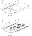
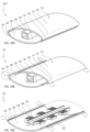
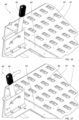
- FIG. 2A shows a cut-out perspective view of another embodiment of a pelt board 10' in the contracted state.
- the third wall element 20 and the fourth wall element 22 comprise actuator members 34 along the longitudinal dimension and the elongated core element 26 comprise cooperating members 36 along the longitudinal dimension.
- the actuator members 34 and cooperating members 36 define opposing wedges.
- the sloping surfaces of the opposing wedges are non-overlapping or overlapping such that no outwardly oriented force is generated, i.e. that the protruding portions of the opposing wedges are non-overlapping.
- the fifth wall element 28 and the sixth wall element 30 comprise actuator members 34' along the longitudinal dimension and the elongated core element 26 comprise cooperating members 36' along the longitudinal dimension.
- the actuator members 34' define curved grooves along the longitudinal dimension of the fifth wall element 28 and the sixth wall element 30 whereas the cooperating members 36 define pins of the core extension element 26'.
- FIG. 2B shows a cut-out perspective view of the pelt board 10' in the expanded state.
- the sloping surfaces of the opposing wedges are now overlapping such that an outwardly oriented force is achieved, i.e. the protruding parts of the opposing wedges are overlapping causing the third wall element 20 and the fourth wall element 22 to move outwardly in opposite directions.
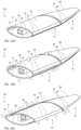
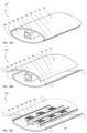
- FIG. 3 shows a perspective view of a further embodiment of a pelt board 10".
- the fifth wall element 28 and the sixth wall element 30 are substantially flat in order to be able to accommodate the neck part of the animal pelt.
- the surface of the arched wall elements 16 18 20 22 have ribs 38 for allowing the pelt to be properly fixated to the pelt board 10". Further all of the wall elements 16 18 20 22 have ventilation holes 40.
- FIG. 4 shows a perspective view of the upper part 14 of the pelt board 10". It shows in detail how the fifth wall element 28 and the sixth wall element 30 both connect to the core extension element 26'.
- the actuator elements 34' in form of curved grooves connect to the cooperating members 36' in the form of pins. By longitudinal movement of the core extension element 26', the pins will follow the path defined by the curved grooves and thus cause the fifth wall element 28 and the sixth wall element 30 to move outwardly along the curve defined by the interaction between the curved grooves and the pins.
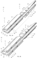
- FIG. 5 shows a perspective view of the lower part 12 of the pelt board 10".
- the first wall element 16 is composed of two elements designated the reference numerals 16A and 16B which are interconnected by means of a snap fit connection 42.
- the second wall element 18 is composed of two elements designated the reference numerals 18A and 18B and which are interconnected by means of a snap fit connection 42.
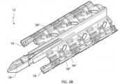
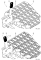
- FIG. 6A shows a perspective view of the lower part 12 of the pelt board 10".
- the present view especially shows a close-up view of the elements 16A 16B 18A 18B making up the first wall element 16 and the second wall element 18, respectively.
- the snap fit mechanisms 42 42' when assembled, define actuator members 34" in the form of pins.
- the elongated core element 26 defines cooperating members 36" in the form of curved grooves.
- the working principle of the curved groove and the pin is the same as for the upper part of the pelt board 10".
- the pins are guided by the curved grooves and forced inwardly/outwardly according to the longitudinal movement of the elongated core element 26.
- the first wall element 16 and the second wall element 18 move along the first radial dimension and at the same time the first wall element 16 and the second wall element 18 are held by the elongated core element 26.
- the wall elements 16A 16B 18A 18B also each comprise a number of respective peripheral parts 44 which are flexibly connected to its corresponding wall elements 16A 16B 18A 18B.
- FIG. 7A shows a close up view describing the functional principle of the elongated core element 26, the wall element 16A and the corresponding peripheral part 44.
- the present view represents the contracted state of the pelt board.
- the elongated core element 26 comprises a further cooperating member 36′′′ constituting a wedge and which is adapted to cooperate with an actuator member 34′′′ constituting a protrusion on the peripheral part 44.
- FIG. 7B shows the setup of FIG. 7B when in the expanded state.
- the elongated core element 26 moves in the longitudinal direction relative to the wall element 16a and causes the wall element 16A to move outwardly in the first radial direction as shown by the arrows.
- the outwardly movement of the wall element 16A is caused by the interaction between the cooperating member 36′′′ and the actuator member 34"'.
- the longitudinal movement of the elongated core 26 causes the actuator member 34′′′ constituting a protrusion to slide on the cooperating member 36′′′ constituting a wedge and thereby the peripheral part 44 is caused to move outwardly in both the first and second radial directions as shown by the arrow.
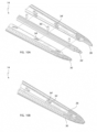
- FIG. 8A shows a perspective view illustrating how the third wall element 20 and the fourth wall element 22 are fastened together and to the elongated core element 26.
- the third and fourth wall elements 20 22 each comprise further actuator members in the form of fastening members 46, which are cooperating with corresponding tracks 48 of the elongated core element 26.
- the third and fourth wall elements 20 22 are in the present embodiment additionally joined together via corresponding clip-on mechanisms 50 50' at the bottom end of the pelt board.
- FIG. 8B shows the lower part 12 of the pelt board when the third wall element 20 and the fourth wall element 22 are fastened together and to the elongated core element 26.
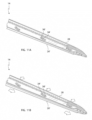
- FIG. 9A shows a close-up view illustrating the working principle of the third wall element 20 and the fourth wall element 22.
- the third wall element 20 and the fourth wall element 22 each comprise actuator members 34 and the elongated core element 26 comprises cooperating members 36.
- the actuator members 34 and the cooperating members 36 define wedges having sloped in opposite direction. In the present contracted state, the wedges of the actuator members 34 and the cooperating members 36 are located such that the protruding parts of the wedges are non-overlapping, allowing the third wall element 20 and the fourth wall element 22 to define a small distance between themselves.
- FIG. 9B shows a close-up view illustrating the working principle of the third wall element 20 and the fourth wall element 22 when in the expanded state.
- the wedges of the actuator members 34 and the cooperating members 36 are located such that the protruding parts of the wedges are overlapping, causing the third wall element 20 and the fourth wall element 22 to define a larger distance between themselves.
- the moving principle of the third wall element 20, the fourth wall element 22 and the elongated core element 26 is illustrated by the arrows.
- FIG. 9C shows a close-up view illustrating the working principle of the fastening member 46 when the pelt board is in the expanded state.
- the fastening member 46 has a wedged shape for controlling the distance between the elongated core element 26 and the respective third wall element 20 and the fourth wall element 22 depending on the longitudinal position of the elongated core element 26.
- the fastening member 46 of the respective third wall element 20 and the fourth wall element 22 grasps the track 48 of the elongated core element 26 which is located opposite the third wall element 20 of which the present fastening member 46 is part of.
- FIG. 9D shows a close-up view illustrating the working principle of the fastening member 46 when the pelt board is in the expanded state.
- the contraction of the wall third wall element 20 and the fourth wall element 22 may be controlled in that the slope of the fastening member causes the third wall element 20 and the fourth wall element 22 to move closer to the elongated core element 26 when the pelt board is assuming the contracted state.
- FIG. 10A shows the mounting principle of the upper part 14.
- the fifth wall element 28 and the sixth wall element 30 are positioned in a partial overlapping position about the core extension element 26'.
- the cooperating members 36' which constitute pins, are positioned through the actuator members 34', which constitute curved grooves, and through the center of the core extension element 26'.
- FIG. 10B shows a perspective view of the upper part 14 when mounted and when in the expanded state.
- FIG. 11A shows the moving principle of the upper part 14 of the pelt board.
- the cooperating members 36' are guided in the actuator members 34' for causing the fifth wall element 28 and the sixth wall element 30 to minimize the radial dimension between themselves and relative to the core extension element 26.
- FIG. 11B shows the moving principle of the upper part 14 of the pelt board.
- the cooperating members 36' are guided in the actuator members 34' for causing the fifth wall element 28 and the sixth wall element 30 to increase the radial dimension between them and relative to the core extension element 26 when the core extension element 26 is moved in the longitudinal direction as shown by the arrows.
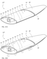
- FIG 12A shows a perspective view of a further embodiment of a pelt board 10"'.
- the pelt board 10′′′ resembles the pelt boards of the previous embodiments however in order to be able to adjust the length of the pelt board 10"', there has been included intermediate sections 52 in-between the upper part 14 and the lower part 12.
- the intermediate sections 52 constitute elliptic cylindrical spacer elements which are non-expandable.
- the intermediate sections 52 may be made non-expandable since the pelt is most likely to stick to the upper part 14 and the lower part 12. However, the intermediate sections 52 may of course also be made expandable similar to the lower part 12 or the upper part 14. For large pelts, a plurality of intermediate sections 52 may be used.
- a core connecting element 26" may be used for interconnecting the elongate core element of the lower part 12 and the core extension element of the upper part 14.
- FIG. 12B shows a perspective view of a third embodiment of a pelt board 10′′′ and illustrates how the lower part 12 and the upper part 14 is expanding as shown by the arrows, while the intermediate sections remain constant in circumference.
- FIG. 13 shows a perspective view of a fourth embodiment of a pelt board 10 IV .
- the present pelt board 56 comprises a number of ribs 56 which contribute to holding the pelt on the pelt board. Further, a number of ventilation holes 40 are present for allowing the pelt to dry quickly.
- the pelt board 10 IV is of elliptical configuration and the third and fourth wall elements 20 22, having an arched configuration, may overlap the first and second wall elements 16 18 in order to assume the expanded state and the contracted state.
- the elongated core element has in the present view been omitted.
- a large opening 58 is present at the bottom end of the pelt board 10 IV for allowing a large amount of dry ventilation air to enter the pelt board 10 IV .
- FIG. 14 shows the bottom end of the lower part 12 of the pelt board.
- the lower ends of the third wall element 20 and the fourth wall element 22 are fixated by means of cooperating clip-on mechanisms 50 50' such that the third wall element 20 and the fourth wall element 22 cannot move in relation to each other adjacent the lower end of the pelt board.
- the pelt does stop a few centimeters above the lower end, otherwise a longer pelt board should be used.
- a connecting element 60 is used for moving the elongated core element 26 in the longitudinal direction.
- first locking protrusions 62 located on each of the third wall element 20 and fourth wall element 22.
- Second locking protrusions 64 are located on the connecting element 60. The locking protrusions 62 64 are used to lock the elongated core element 26 in the expanded state. This will be explained further below.
- FIG. 15 shows the lower part 12 of the pelt board when it has been assembled.
- the connecting element 60 extends from an opening 58' at the lower end of the pelt board.
- the opening 58' is preferably large for allowing a large flow of air to enter the interior of the pelt board 10 and most preferably the opening 58' defines the greater part of the entire bottom surface of the pelt board 10.
- the opening 58' typically constitutes the limiting flow surface which determines the amount of air which will flow through the pelt board. A small opening 58' would limit the flow which would cause a less efficient drying of the pelt.
- FIG. 16 shows a perspective close up of the connecting element 60 and the locking principle employed to lock the pelt board in the expanded state.
- the third and fourth wall elements comprise first locking protrusions 62, whereas the connecting element 60 comprises second locking protrusions 64.
- the connecting element 60 is flexible in the first radial direction in relation to the third and fourth wall elements.
- the present locking mechanism is located adjacent the bottom end of the pelt board and together with the friction between the internal moving parts of the pelt board, i.e. the actuator members and the cooperating members, it will eliminate the need of any further locking mechanisms inside the pelt board.
- the present locking mechanism should be located adjacent the bottom end of the pelt board in order to avoid it being jammed by fatty substances which may come from the pelt.
- the change from expanded state to contracted state may preferably be made when the bottom end of the elongated core element is attached to the drying unit, e.g. by tilting the pelt board sideways, thereby also taking advantage of the leverage provided by the pelt board for overcoming the friction between the first and second protrusions.
- FIG. 17A shows the locked position of the pelt board.
- the first locking protrusions 62 are located below the second locking protrusions 64.
- the first locking protrusion 62 thus prevents the longitudinal movement of the connecting element 60 and thus of the elongated core element.
- FIG. 17B shows the unlocking of the pelt board.
- FIG. 17C shows the movement from expanded state to contracted state of the unlocked pelt board.
- FIG. 17D shows the connecting element 60 when the pelt board is in the contracted state. By releasing the connecting element 60, it flexes back to its central relaxed position.
- FIG. 18A shows a perspective view of a further embodiment of a pelt board 10 V when in the contracted state.
- the pelt board 10 V comprises movable wall elements 16, 16', 16", 18, 18', 18", 20, 22 which together do not cover the complete circumference of the pelt board.
- the wall elements 16, 16', 16", 18, 18', 18", 20, 22 form an even outer surface together with the fixed wall elements 54.
- FIG. 18B shows a perspective view of a further embodiment of a pelt board 10 V when in the expanded state.
- the wall elements 16, 16', 16", 18, 18', 18", 20, 22 move outwardly and form contact surfaces for the pelts.
- the moving principle of the wall elements 16, 16', 16", 18, 18', 18", 20, 22 have not been shown, however, preferably the same principles are used as for the previous embodiments.
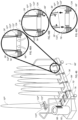
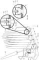
- FIG. 19 shows the pelt board during drying when connected to a drying unit 66.
- the drying unit 66 has a ventilator 68 and a number of ventilation apertures 70.
- the ventilator produces a flow of air which is led via the ventilation apertures 70 into the pelt board 10 through the openings 58' at the lower part 12 of the pelt board 10.
- FIG. 20A shows a perspective view of a further embodiment of the pelt board 10 VI , in which the first wall element 16 is integrally joint to the third wall element 20 as indicated by a line of junction 17 and similarly, the second wall element 18 is integrally joint to the fourth wall element 22 through a line of junction 19.
- the embodiment of the pelt board 10 VI shown in FIGS. 20A - 20C presents the further feature of allowing the pelt board to be expanded in two alternative and separate directions; a first direction shown in FIG. 20B as indicated by arrows, according to which expansion the third wall element and the fourth wall element 22 are separated from one another for expanding the pelt board in a first transversal direction and likewise in FIG.
- the expansion of the pelt board 10 VI is caused by shifting the first wall element 16 and the second wall element 18 relative to one another for expanding the pelt board in a direction indicated by arrows in FIG. 20C , which direction is orthogonal to the direction of expansion shown in FIG. 20B .
- FIGS. 21A and 21B illustrate in greater details the expansion of the pelt board 10 VI in the first transversal direction indicated in FIG. 20B and similarly, in FIG. 22A and 22B , the expansion in the second transversal direction is illustrated in greater details.
- the expansion in the second transversal direction is accomplished as a further movement of the elongated core element 26 as the movement of the central core element 26 from the position shown in FIG. 20A to the position shown in FIG. 20B accomplishes the expansion of the pelt board in the first transversal direction and further motion of the central core element 26 as indicated in FIG. 20C creates the further expansion in the second transversal direction.
- the actuator members 34, 36 and 46, 48 or repositioning them relative to one another the shifting from the non-expanded state to the full expansion shown in FIG.
- the shifting of the pelt board from the non-expanded state to the first or the second expanded states shown in FIGS. 20B and 20C , respectively, may be accomplished selectively by shifting the central core element 26 sidewise in order to contact the one set of actuators 34, 36 shown in FIG. 21B , or alternatively the second set 46, 48 shown in FIG. 22B .
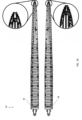
- FIGS. 24-27 illustrate a 3-component embodiment of the pelt board 10 IV .
- the two shell parts 28 and 29 are shown exposing the exterior surfaces of the two shell parts and in addition, in the left hand part of FIG. 24 exposing the upper ends of the two shell parts, which upper ends serve to catch and fixate a part of the pelt at the head of the pelt.
- the upper ends are provided with catching claws or teeth serving to fixate the head of the pelt relative to the pelt board.
- FIG. 25 the two shell parts 28 and 30 are shown in disassembled state exposing the central elongated core element 29 having at its lower end an outwardly protruding part serving to cooperate with a conventional tanning machine and a conventional drying machine.
- the above described presently preferred embodiment 10 VI fulfill the following features characteristic of the embodiment.
- the shell parts 28 and 30 are forcedly guided relative to the elongated core element 29 at a total of six locations along the shell parts, as the forcedly guiding or controlling is established during expansion of as well as during collapsing of the pelt board.
- the locks of the pelt board serve as a frictional lock preventing collapsing and expansion of the pelt board until an outer force generated by a pelt position on the pelt board activates the lock.
- the expansion in both transversal directions and likewise the collapsing in both transversal directions is forcedly controlled and guided.
- the above stubby elements together with the lower end of the shell parts serve to center the pelt board in a drying box or drying machine and provides a stop in the drying box.
- the stubby element as distinct from previously used stubby elements serving to catch and lock in the tanning machine and in the drying box or drying machine provides gripping flanges or elements for an improved fixation.
- the pelt board is further provided with an internal holder for receiving an RFID (Radio Frequency Identification Device).
- the shell parts further exhibit the following additional features by providing holes for the drying of the back part of the pelt and providing an increased air through flow as compared to conventional and commercially available pelt boards.
- the shell parts are reinforced every 60 mm and transversal bands are further provided every 30 mm.
- the overall surfaces of the two shell parts prevent vertical shifting of the pelt relative to the pelt board, and the teeth at the upper ends of the two shell parts fixate the upper end, i.e. the head of the pelt relative to the pelt board.
- the number of teeth for catching the head of the pelt may be constituted by any arbitrary numbers such as 2, 4, 6, 8 or even further teeth as the presently preferred embodiment exhibit a total of four teeth in each of the two shell parts 28 and 30.
- the assembled pelt board 10 VI shown in FIGS. 24-27 further provide the advantage of collapsing the pelt board in its entire length and allows for machinery operated removal of the pelt from the pelt board.
- the overall cross section of the pelt board is similar to the geometry of an ellipse in the non-expanded or collapsed state, which provides an improved function as to easy mounting of the pelt and easy removal of the pelt after collapsing the pelt board.
- the high number of air apertures serving to allow air to circulate through the pelt board and further through the pelt allows for the drying air to be passed from the inside of the pelt board to the outside.
- the overall opening air layer of the overall transversal opening area of the pelt board is approximately 1200 mm 2 calculated as the open area.
- the air is, as is evident from FIGS. 25 and 26 guided inside the pelt board along approximately 60% of the overall length of the pelt board and then transferred to the outer surface of the pelt board through the apertures shown in the enlarged views A and B of FIGS. 26 .
- FIG. 28A shows a perspective view of a part of a further embodiment of a pelt board 10 VII in its contracted or non-expanded state.
- the pelt board 10 VII resembles the above described embodiments 10 VI shown in Fig. 20A, 20B, 20C , 21A, 21B , 22A, 22B , 23A, 23B and 23C .
- the part of the pelt board 10 VII shown in FIG. 28A constitutes the lower part 12 I of the pelt board, which is shown in FIGS. 31A and 31B , which will be described in greater details below.
- the lower part 12 I of the pelt board 10 VII is composed of a total of three components, namely two identically shaped shell parts 72 and 74 and a central elongated core element 26.
- Each of the shell parts 72 and 74 comprise a major low curvature wall part 22 I and 20 I , respectively, and a minor high curvature wall part 18 I and 16 I , respectively.
- the major low curvature wall parts 22 I and 20 I are joint to the minor high curvature parts 18 I and 16 I , respectively, through imaginary lines 17 I and 19 I , respectively.
- the embodiment of the pelt board 10 VII shown in FIG. 28A is of a structure, in which the two identically shaped shell parts 72 and 74 in the contracted or non-expanded state shown in FIG. 28A constitute an almost perfectly configured elliptical cross sectional configuration as the longitudinal edges of the oppositely positioned shell parts 72 and 74 join one another in a basically unbroken elliptically cross sectional configuration.
- FIG. 28B the embodiment of the pelt board 10 VII is shown in its expanded state, in which the two shell parts 72 and 74 are caused to be shifted away from one another establishing a gap between the edges of the oppositely positioned shell parts 72 and 74.
- the shift of the shell parts 72 and 74 away from one another as illustrated in FIG. 28B and indicated by arrows is accomplished by shifting the central elongated core element 26 in a direction also indicated by an arrow inwardly into the interior of the pelt board 10 VII forcing the shell parts 72 and 74 away from one another.
- the separation or the shifting of the shell parts 72 and 74 is accomplished by means of cooperating actuator elements 34 and 36 shown in FIG. 28C identical to the actuator elements 34 and 36 shown in Fig. 21B and described above, the actuator elements 34 being constituted by triangularly shaped bodies extending inwardly from the central part of the major low curvature wall part 22 I of the shell part 72 and likewise from the major low curvature wall part 20 I of the shell part 74, and the central elongated rod 26 is provided with actuator members 36 defining cooperating sloping cam surfaces with which the actuator members 34 cooperate for pushing the shell parts 72 and 74 away from one another to the expanded state shown in FIG. 28C .
- FIGS. 29A, 29B and 29C a further embodiment of the pelt board 10 VIII is shown having the same shell parts 72 and 74 as illustrated in FIGS. 28A, 28B and 28C as described above and the central elongated core element 26.
- the expansion of the pelt board is established as a vertical separation by pushing the shell parts away from one another
- the second embodiment shown in FIGS. 29A, 29B and 29C establishes the expansion of the pelt board by shifting the shell parts 72 and 74 sidewise as illustrated in FIG. 29B and as accomplished by the cooperation between actuator members 34 I and 36 I shown in Fig. 29C .
- FIG. 29B the shell part 72 is shifted to the right and similarly, the shell part 74 is shifted to the left relative to the central elongated core elements 26.
- FIGS. 30A, 30B and 30C a modified or alternative embodiment of the further embodiment 10 IX shown in FIGS. 29A, 29B and 29C , respectively, is illustrated differing from the above described further embodiment 10 VIII in that the modified embodiment shifts the shell parts 72 and 74 in opposite directions as compared to the shifting shown in FIG. 29B and as illustrated in FIG. 30B , the shell part 72 is shifted to the left and simultaneously, the shell 74 is shifted to the right as accomplished by the modified cooperating actuator members 34 II and 36 II .
- FIGS. 31A and 31B the entire pelt board 10 VII is shown having in addition to the lower part 12 I shown in FIG. 28A , an upper part 14 constituting a geometrical extension and continuation of the lower part 12 I and having a tapering configuration.
- the upper part 14 I also comprises two shell parts 28 I and 30 I which, like the shell parts 72 and 74 of the lower part 12, are caused to be separated similar to the separation of the shell parts 72 and 74 of the embodiment 10 VII described above with reference to FIGS 28A, 28B and 28C . It is readily understood that the separation of the two shell parts 28 I and 30 I of the upper part 28 I is accomplished in the same manner as described above with reference to FIGS.
- the complete pelt board 10 VII shown in FIGS. 31A and 31B may be modified into establishing the sidewise expansion described above with reference to FIGS. 29A, 29B and 29C and also FIGS. 30A, 30B and 30C .
- FIG. 32 and FIG. 33 illustrate in greater details a further embodiment 10 X of the pelt board , which embodiment exhibits the highly advantageous feature of being composed of no more than three components, namely two identically shaped shell parts 72 I and 74 I and the central core element 36.
- the shell parts 72 I and 74 I integrally comprise the shell parts 72, 72 and 28 I , 30, respectively, of the embodiment 10 VII of the pelt board, as the shell parts 72 and 72 and similarly the shell parts 28 I and 30 I of the lower and upper parts 12 I and 14 I , respectively, of the pelt board 10 VII are constituted by a single integral component 72 I and 74 I , respectively.
- the central elongated core element serving to shift in a forced manner the shell parts 72 I and 74I from the contracted or non-expanded state to the expanded state and vice versa serve to engage with the actuator elements of the shell parts 72 I and 74 I .
- FIGS. 34 and 35 a presently preferred embodiment of a drying unit constituting a wheeled or movable carriage is shown designated the reference numerals 66 I in its entirety.
- the drying unit includes a housing constituting a shallow box 80 having an apertured plate 76 and sealed off or closed sidewalls. Below the housing 80, the drying unit is provided with four wheels, one of which is designated the reference numeral 78.
- a hollow and apertured housing extension 82 is provided, on which a ventilator is to be mounted in a position similar to the position of the ventilator 68 shown in FIG. 19 .
- the wheeled or movable carriage constituting the presently preferred embodiment of the drying unit 66 I is further provided with two carriage handles 81 and 81 I positioned at opposite ends of the shallow box 80, the one carriage handle being composed of straight line bars, whereas the handle 81 I is a cranked carriage handle as the cranked carriage handle 81 I is positioned juxtaposed a separation wall 83, which is located between the aperture housing extension 82 and the housing 80 and serving the purpose of preventing air from being sucked into the ventilator not shown in the drawing from the pelt boards positioned and received in the drying unit, as the drying would be short-circuited by the reentrance of air from the pelt boards into the ventilator and into the drying unit deteriorating, without the presence of the separation wall 83, the drying process.
- the ventilator is omitted in FIGS. 34 and 35 for disclosing the interior of the aperture housing extension 82.
- FIGS. 34A and 35A are enlarged scale views of two apertures 70 I of the top plate 76 of the drying unit 66 I illustrated in FIG.34 , in which the handle 84 is in its first position, and free access through the apertures 70 I of the top plate into the interior of the housing 80 is provided, whereas in FIG.
- a locking plate 88 is shifted into the free passage through the aperture 70 I serving to lock a pelt board positioned on the top plate 76 of the drying unit in its intentional position and preventing the pelt board 10 X from being disconnected from the drying unit per se in a way well known in the art.
- FIGS. 36 and 37 illustrate in greater details similar to the views of FIGS. 34 and 35 , respectively, the top plate 76 of the drying unit, as the handle 84 is in FIG. 36 in its first position similar to the position shown in FIG. 34 and in FIG. 37 in the second position, similar to the position of FIG. 35 , and establishing the locking of the pelt boards to the top surface of the drying unit by the locking plates, one of which is designated the reference numeral 86 by engagement with the connector of the pelt board, which connector will be described in greater details below with reference to FIG. 41 .
- the presently preferred embodiment of the drying unit 66 I may be provided with closing off plates closing or sealing off the individual apertures 70 I of the top plate 76 of the drying unit 66 I , which closing off plates are journalled at the one side of the apertures opposite to the side from which the locking plate 86 are pushed into engagement with the connector of the pelt board, as the locking plates are spring biased and seal off the apertures 70 I , which are not opened by the introduction of a connector of a pelt board, and the apertures, which are not opened by the introduction of the cooperating connector of the pelt board are kept sealed off as the forward motion of the locking plate 86 to the positions shown in FIGS. 35A and 37 prevents the locking plates from being pushed aside after the handle 84 has been moved to its second position shown in FIGS. 35 and 37 .
- FIGS. 38 and 39 sets of locking plate assemblies 88 having individual locking plates 86 for catching and locking a connector received within a top plate aperture 70 I are shown.
- the locking plate assemblies are shifted to their first position similar to the position of the handle 84 being in its first position and, as illustrated in FIG. 39 , the locking assemblies 88 are moved as indicated by arrows by shifting the handle 84 to its second position also shown and indicated by an arrow for shifting the locking plate 86 from the positions shown in FIGS. 34 and 36 to the positions shown in FIGS. 35 and 37 .
- FIG. 40 the presently preferred embodiment of the pelt board 10 X is shown mounted on the top plate 76 of the presently preferred embodiment of the drying unit 66 I described above with reference to FIGS. 34-37 .
- the pelt board 10 X mounted on the top plate 76 is shown in the left hand side of FIG. 40 and along with the top plate 76, the locking plate assembly 88 is shown together with a further plate 90, which is positioned below the locking assemblies 88 and serves to align the pelt board 10 X in its intentional vertical position as the pelt board is locked to the top surface 76 by the locking plate 86 catching into the connector of the pelt board 10 X , which connector is shown in FIG. 41 and designated the reference numeral 100.
- the bottom surfaces of the shell parts 42 and 74 are designated the reference numerals 102 and 104, respectively.
- FIG. 40A the contour of the bottom surface or a horizontal sectional view through the bottom end of the pelt board 10 X is shown indicating the size of the bottom surfaces 102 and 104 and the fairly small area of the bottom end covered by the connector 100 within the through-going aperture defined or delimited between the shell parts 72 and 74.
- FIG. 40B the aperture 70 I of the top plate 76 is shown and likewise, in FIG. 40C , the plate 90 having a through-going aperture 92 is shown, which aperture is aligned with the aperture 70 I of the top plate and also the free through-going area delimited between the inner surfaces of the shell parts 72 and 74, into which the connector 100 extends.
- FIG. 41 the lower end of the presently preferred embodiment of the pelt board 10 X is shown illustrating the bottom surfaces 102 and 104 of the shell parts 72 and 74, respectively, and further, the free area delimited at the bottom end, in which the connector 100 is received.
- a total of six air passages are provided into the interior of the pelt board 10 X as distinct from the air inlet into a conventional connector of the kind described in the prior art as a "stubby element" and implemented in the commercial products produced by the applicant company and known as a 'FIX-tane 2' and also by the competitor company Jasopels A/S, which competitor company's product is known as 'XL tane'.
- the overall cross sectional area of the connector giving access into the interior of the pelt board via inlet passages or slots in the prior art connector measures 400 mm 2 as the peripheral length of the aperture is 80 mm.
- the aperture into the interior of the presently preferred embodiment of the pelt board 10 X through the bottom surfaces 102 and 104 measures 1518mm 2 , i.e. measures approximately four times the area of the conventional pelt board products.
- two side walls 106 and 108 are provided, which are interconnected by a transversal wall 110, the top surface of which serves to cooperate with the locking plate 86 described above, as the connector is received in its intentional position relative to the top plate 76 of the drying unit 66 I .
- the side walls 106 and 108 are further continued into a bottom pointed end part constituted by two sloping and tapering walls 112 and 114, which are joined by a small planar end wall 116.
- sloping guiding element 118 and 120 are provided at the outer faces of the side walls 106 and 108.
- FIG. 42 illustrates three curves, a dashed line, a dotted line and a solid line, illustrating the pressure needed for generating a specific flow of air into the pelt board in question
- the dashed line illustrates the correspondence between the pressure needed for generating the air inlet into a conventional pelt board, such as the above mentioned 'FIX-2 tane' produced by the applicant company and similarly, the 'XL tane' produced by the competitor company Jasopels A/S
- the dotted line illustrates the results obtained by measurement on a prototype of the pelt board 10 X described above with reference to FIGS. 32 , 33 and 41
- the solid line curve illustrates the "ideal" curve of a pelt board having an inlet area of 90% as compared to the outer contour of the pelt board 10 X
- the outer contour of the pelt boards is determined by the standard of the company Kopenhagen Fur, for which reason the conventional pelt board produced by the applicant company and the competitor company Jasopels A/S, and the new pelt board in any embodiment described herein before or afterwards and also the pelt board shown as indicated referring to the solid line of FIG 42 all have an outer area of approximately 3300mm 2 .
- the "ideal" pelt board having an inlet area of 90% (delimited by the wall thickness of the pelt board) will have an inlet area of approximately 3000mm 2 , i.e. less than twice the inlet area of the presently preferred embodiment of the pelt board 10 X having an inlet area of 1518mm 2 . It is to be understood that the solid line of FIG 42 was recorded by using the outer shell of the presently preferred embodiment of the pelt board 10 X , i.e.
- FIG. 42 illustrates the shortcoming of the conventional pelt boards as is evident from FIG. 42 , the increase of a volume above 20m 3 /h to a double volumetric input, such as an input of 40m 3 /h necessitates the increase of the pressure by a factor 4 and in addition, as is evident from FIG. 42 , the dashed line becomes above 40m 3 /h fairly steep indicating that the limit as to the maximum volume input into the pelt board by increasing the pressure is about to be reached at 4hPa.
- the prototype of the presently preferred embodiment of the pelt board clearly allows for a far larger air input than the conventional pelt board as the curve at its right hand end is still far from being steep and exhibits a fairly linear relation between the pressure increase and the volume input increase, as the pressure of approximately 1.5hPa generates a volumetric input of 25-30m 3 /h at an increase to 3.0hPa of the inlet pressure almost doubles the air input.
- the dotted line is fairly close to the "ideal" solid line indicating that any further increase of the inlet area into the interior of the pelt board will have minor influence on the drying capability of the pelt board as compared to the substantive change from the conventional "stubby element" delimiting the air inlet of the conventional pelt boards as compared to the improved new pelt board.
- a further embodiment of the drying unit designated the reference numeral 66 II is shown, which drying unit is of a configuration similar to the one described above with reference to FIGS. 34-39 , however, differing from the above described presently preferred embodiment in that the drying unit 66 II constitutes a universal drying unit, which may be modified or adapted to a specific pelt board by the use of an adaptor constituting an interface between the pelt board and the drying unit.
- the universal drying unit 66 II comprises a top plate 76 I differing from the top plate 76 of the above described presently preferred embodiment of the drying unit in that the top plate is provided with fairly large apertures, one of which is designated the reference numeral 70 II , which apertures serve to receive a replaceable adaptor, which constitutes an interface between the universal drying unit and the pelt board in question, as the adaptor is adapted to the pelt board in question and is receivable within the aperture 70 II of the universal drying unit 66 II .
- the adaptor 22 is configured for cooperating with a conventional pelt board, such as the pelt board produced by the applicant company and named 'FIX-tane 2' and also the pelt board manufactured and sold by the competitor company Jasopels A/S.
- a conventional pelt board such as the pelt board produced by the applicant company and named 'FIX-tane 2' and also the pelt board manufactured and sold by the competitor company Jasopels A/S.
- the pelt board commercially exploited by the applicant company is described in several patent applications, among others European patent 1 680 520 , corresponding US patent 7,690,228 .
- the universal drying unit 66 II has a handle 84 I serving to operate the adaptors positioned in a row juxtaposed the handle in question.
- FIG. 43-48 includes a total of four handles 84 I for the cooperation with three adaptors in each row operated by the handle in question.
- the operation of the handle 84 I allows the adaptor 122 to be blocked to the universal drying unit 66 II as is illustrated in FIGS. 43A and 43C , as the connector 122 is in the enlarged cross sectional view of FIG. 43A locked in position as two opposing tongues 124 operated by the handle 84 I are introduced into and locks within a corresponding recess 126 in the adaptor 122.
- FIG. 43C the locking tongues 122 are shifted to a position concealed below the top plate 76 I of the universal drying unit 66 II allowing the adaptor 122 to be removed from the universal drying unit 66 II .
- FIG. 43C the locking tongues 122 are shifted to a position concealed below the top plate 76 I of the universal drying unit 66 II allowing the adaptor 122 to be removed from the universal drying unit 66 II .
- the conventional pelt board 130 is removed from its position received within the adaptor 122 as shown in FIG. 43A , in which position shown in FIG. 43 the limited air inlet capability of the conventional pelt board 130 is illustrated by the arrows indicating the flow through the so-called "stubby element" of the conventional pelt board.
- the removal of the conventional pelt board 130 is, as is illustrated in Fig. 43B , simply accomplished by lifting the conventional pelt board off the adaptor 122.
- the universal drying unit 66 II is shown, however, including an alternative embodiment of the adaptor, which adaptor is designated the reference numeral 122 I and is configured and adapted to cooperate with a further embodiment of the pelt board 10 XI , which pelt board is a hollow structure in which the central elongated core element 26 described above is substituted by two actuator pins 26 I , which are acted by of a top inner flange 128 of the adaptor 122 I , which flange 128 serves the additional purpose of firstly arresting the pelt board 10 XI relative to the adaptor 122 I , as an inner circumferential bead of the pelt board 10 XI catches into a circumferential recess of the flange 128 of the adaptor 122 I .
- FIG. 44B the disconnection of the pelt board 10 XI , from the universal drying unit 66 II is accomplished by the lifting of the pelt board relative to the universal drying unit 66 II and in doing so, disconnecting the circumferential inner bead of the pelt board from the circumferential recess of the flange 128 of the adaptor 122 I .
- FIG. 44C the disconnection of the adaptor 122 I from the universal drying unit 66 II is illustrated similar to the view of FIG. 43C . In FIG.
- a variant or modified version of the universal drying unit is shown, in which a three position handle 84 II is included, which handle defines three positions: A first position, in which the adaptor 122 II is disconnected from the universal drying unit, as the locking tongues 124 are retracted from their catching into the recesses 126 of the adaptor 122".
- a second position of the handle 84 II the adaptor 122 I is arrested relative to the universal drying unit similar to the above disclosure of the first and second embodiments of the adaptors shown in FIGS. 43 and 44 , respectively, and illustrated and described with reference to FIGS. 43A and 44A , respectively.
- the third embodiment of the adaptor 122 II has a pair of arresting catchers 132, which may be shifted from their position shown in FIG. 45A , in which the catchers serve the same purpose as the top flange 128 of the second embodiment of the adaptor 122 I described above with reference to FIG. 44 and may be shifted, as the handle 84 II is shifted to its third position so as to disengage the catchers from the circumferential bead of the inner surface of the pelt board 10 XI , and in doing so, also disengaging the actuators 26 I for shifting the pelt board from its expanded position to a non-expanded position.
- the pelt board may, as is illustrated in FIG. 45C , easily be lifted and removed from the universal drying unit 66 II as shown in FIG. 45C .
- the pelt board 10 XI is, as described above, arrested by the catching of a circumferential bead at the inner surface of the pelt board at its lower end within a circumferential recess or recess of catchers, whereas in FIG. 46 , the arresting of the pelt board relative to its cooperating adaptor 122 III is established by a circumferential bead extending outwardly from the lower end of the pelt board cooperating with an external set of catchers 132 I . Whereas the disconnection of the pelt board 10 XI from the adaptor 122 II is established by shifting the handle 84 II of the second embodiment of the universal drying unit 66 II shown in FIGS.
- the operation of the handle 84 III of the third embodiment of the universal drying unit 66 II shown in FIG. 46 to its third position provides shifting of the catchers 132 I outwardly relative to the pelt board 10 XII as is illustrated in FIG. 46B .
- the pelt board 10 XII is easily lifted off the connector 122 III as is shown in FIG. 46C .
- the disconnection of the adaptors 122 II and 122 III shown in FIGS. 45 and 46 , respectively, is as described above established by the shifting of the handle designated the reference numeral 84 II and 84 III , respectively, to the above described third position.
- FIG. 47 the technique illustrated in FIG. 45 is slightly modified in that the disconnection of the arresting catchers 132 shown in FIGS. 44A , 45B and 45C by shifting the catchers inwardly, is in FIG. 47A and 47B modified into a tilting of the catchers, as is illustrated in FIG. 47B , which tilting from FIG. 47A to FIG. 47B is accomplished by shifting the handle 84 I of the fourth embodiment of the universal drying unit 66 II shown in FIG. 47 to its third position and in doing so, disconnecting the catchers from the inwardly protruding circumferential bead of the inner surface of the pelt board 10 XI .
- the tilting catchers shown in FIGS. 47A-47C are designated the reference numeral 132 II .
- FIG. 48 a fifth embodiment of the universal drying unit 66 V is shown, in which the operation of the handle 84 V to its third position establishes a slightly modified function as compared to the function of the outwardly shiftable catchers 132 I described above with reference to FIG. 46 , as the catchers 132 I shown in FIG. 46 are modified in accordance with the technique described above with reference to FIG. 47 , as the catchers 132 III shown in FIG. 48 are tiltable for causing the catchers to disengage from the outwardly extending circumferential bead of the pelt board 10 XII .
- FIGS. 49 , 50 , 51 and 52 are shown a sixth, seventh, eighth and ninth embodiment of the drying unit and designated the reference numeral 66 VI , 66 VII , 66 VIII and 66 IX .
- the sixth, seventh, eighth and ninth embodiments of the drying unit differ from the above described universal drying unit shown in FIGS. 43-46 , as the drying units shown in FIGS. 49 , 50 , 51 and 52 are dedicated to a specific pelt board configuration and implementing the arresting technique described above with reference to FIGS. 45 , 46 , 47 and 48 , respectively. No further description of the sixth, seventh, eighth and ninth embodiments of the drying unit is to be presented.
- FIGS. 53 and 54 a tenth and eleventh embodiment of the drying unit is shown, in which tenth embodiment designated the reference numeral 66 X is a dedicated drying unit implementing the technique described above with reference to FIG. 44 , i.e. a technique according to which the pelt board 10 XI is fixated to a fixed circumferential flange 128 by the catching of an inner circumferential bead of the pelt board 10 XI , within a recess of the flange 128.
- the eleventh embodiment of the drying unit 66 XI shown in FIG. 54 is modified relative to the tenth embodiment shown in FIG. 53 in that the embodiment of FIG.
- FIG. 55 the above described sixth embodiment of the drying unit 66 VI is shown in combination with an adaptor allowing the sixth embodiment 66 VI of the drying unit to be used in combination with a conventional pelt board 130 of the kind described above and commercially exploited by the applicant company, as the adaptor designated the reference numeral 134 serves to cooperate with the arresting catchers 132 of the drying unit as described above with reference to FIG. 49 .
- the adaptor 134 has a configuration resembling the lower end of the conventional pelt board 130 and also the pelt boards, as the configuration of the pelt boards is as mentioned above determined according to the requirements defined by the company Kopenhagen Fur.
- the outer peripheral wall of the adaptor 134 consequently constitutes an extension of the wall of the conventional pelt board 130 and has at its lower end an inwardly protruding bead similar to the inwardly protruding bead of the eleventh embodiment of the pelt board 10 XI , catching with the arresting catchers 132 of the drying unit 66 VI .
- the conventional pelt board 130 has a downwardly extending so-called “stubby element" or connector, which is received within a circumferential wall extending downwardly from a top surface of the connector and serving to contact the connector of the conventional pelt board 130 as is illustrated in FIG. 55A .
- FIG. 56 a twelfth embodiment 56 XII of the drying unit is shown, which drying unit constitutes a combination of the techniques of the tenth embodiment 66 X of the drying unit shown in FIG. 53 and the engaging/disengaging technique of the sixth embodiment 66 VI of the drying unit according to the version shown in FIG. 49 .
- the adaptor 134 is permanently connected with the conventional pelt board 130, as the adaptor is preferably glued to the lower side surface of the conventional pelt board 130 in order to establish a permanent fixation of the adaptor 134 to the conventional pelt board 130, the technique shown in FIG.
- the twelfth embodiment 66 XI of the drying unit includes, as distinct from the above described embodiments, a pair of catching elements 166 serving to be engaged with the cooperating lower end of the connector of the conventional pelt board 130 and catching behind a planar bottom wall of the connector, as is illustrated in FIG. 56A .
- the catching elements 166 are retracted for disconnection from the connector of the conventional pelt board 130 and allowing the conventional pelt board 130 to be raised from its position received within the adaptor 134 I as is illustrated in FIG. 56B .
- the adaptor 134 I may itself be disconnected from its arresting contact with the drying unit as is illustrated in FIG. 56C by clicking off the adaptor in accordance with the technique described above with reference to FIG. 53 .
- the catching elements 136 are, as is illustrated in FIG. 56C raised from the drying unit 66 XI leaving a pair of inwardly protruding arms 138 free from contact with the catching elements 136.
- the embodiment shown in FIG. 56 may be modified from the technique described with reference to FIG. 53 into the operable disconnection techniques described above with reference to FIGS. 49-52 .
- pelt boards such as the eleventh and twelfth embodiments of the pelt boards designated the reference numerals 10 XI and 10 X II , respectively
- a further adaptor is deduced.
- FIG. 57 a conventional drying unit 166 is shown, in which the top plate 76 is provided with fairly small 20mm x 20mm holes for receiving and fixating the connector of the conventional prior art pelt boards, such as the FIX-tane 2 produced by the applicant company, and the corresponding competitive product of the competitor company Jasopels A/S.
- the adaptor 134 II allowing the use of the pelt board in combination with a conventional drying unit 166 may be implemented in accordance with any of the above described catching techniques described with reference to FIGS. 43-54 , however, in FIG. 57 , the catching and arresting technique described above with reference to FIG. 44 , and similarly FIG. 53 , is implemented as the adaptor 134 II is at its upper end provided with a circumferential flange 128 I having a recess for cooperating with the inwardly protruding bead at the lower end of the pelt board 10 XI . At its bottom end, the adaptor 134 II is provided with a connector similar to the connector of the conventional or prior art pelt board 130 described above with reference to FIGS. 55 and 56 .
Landscapes
- Engineering & Computer Science (AREA)
- Mechanical Engineering (AREA)
- Chemical & Material Sciences (AREA)
- Organic Chemistry (AREA)
- Manufacturing & Machinery (AREA)
- Drying Of Solid Materials (AREA)
- Housing For Livestock And Birds (AREA)
- Air-Flow Control Members (AREA)
Claims (12)
- Längliches Pelzbrett (10) zum Aufnehmen eines Tierfells, wobei das Pelzbrett eine Längsrichtung, eine erste radiale Richtung senkrecht zu dieser Längsrichtung und eine zweite radiale Richtung senkrecht zu dieser Längsrichtung und der ersten radialen Richtung definiert, wobei das das Pelzbrett (10) folgendes umfasst:ein erstes Wandelement (16), das sich entlang der Längsrichtung erstreckt und eine nach außen gerichtete erste Oberfläche, eine nach innen gerichtete erste Oberfläche, ein erstes Set von gegenüberliegenden Längskanten und ein erstes Aktuatorelement definiert,ein zweites Wandelement (18), das sich entlang der Längsrichtung erstreckt und eine nach außen gerichtete zweite Oberfläche, eine der ersten nach innen gerichteten Oberfläche zugewandte zweite nach innen gerichtete Oberfläche, ein zweites Set von gegenüberliegenden Längskanten und ein zweites Aktuatorelement definiert,wobei das erste Wandelement (16) und das zweite Wandelement (18) eine identische Konfiguration aufweisen und jedes einen ersten Krümmungsteil und einen zweiten Krümmungsteil aufweist, die entlang einer Verbindungslinie verbunden sind, die sich im Allgemeinen in der Längsrichtung erstreckt, wobei der erste Krümmungsteil eine geringere Krümmung als der zweite Krümmungsteil aufweist,wobei der erste Krümmungsteil des ersten Wandelements (16) eine erste Längskante des ersten Satzes von gegenüberliegenden Längskanten definiert, der zweite Krümmungsteil des ersten Wandelements (16) eine zweite Längskante des ersten Satzes von gegenüberliegenden Längskanten definiert, der erste Krümmungsteil des zweiten Wandelements (18) eine erste Längskante des zweiten Satzes von gegenüberliegenden Längskanten definiert, der zweite Krümmungsteil des zweiten Wandelements (18) eine zweite Längskante des zweiten Satzes von gegenüberliegenden Längskanten definiert, wobei die erste Kante des ersten Wandelements (16) dem zweiten Rand des zweiten Wandelements (18) gegenüber positioniert ist und die erste Kante des zweiten Wandelements (18) dem zweiten Rand des ersten Wandelements (16) gegenüber positioniert ist, wobei die nach innen gerichtete erste Oberfläche und die nach innen gerichtete zweite Oberfläche zusammen eine Höhlung (24) entlang der Längsrichtung definieren,wobei das erste Wandelement (16) und das zweite Wandelement (18) folgendes definieren:einen kontrahierten Zustand, in dem der erste radiale Abstand zwischen der nach innen gerichteten ersten Oberfläche und der nach innen gerichteten zweiten Oberfläche reduziert ist, in dem die erste Kante des ersten Wandelements (16) dicht an der zweiten Kante des zweiten Wandelements (18) positioniert ist und in dem die erste Kante des zweiten Wandelements (18) dicht an der zweiten Kante des ersten Wandelements (16) positioniert ist, und einen erweiterten Zustand, in dem der erste radiale Abstand zwischen der nach innen gerichteten ersten Oberfläche und der nach innen gerichteten zweiten Oberfläche vergrößert ist, in dem der erste Rand des ersten Wandelements (16) und der zweite Rand des zweiten Wandelements (18) in einer räumlich getrennten Beziehung in der ersten oder zweiten radialen Richtung positioniert sind, und in dem der erste Rand des zweiten Wandelements (18) und der zweite Rand des ersten Wandelements in einer räumlich getrennten Beziehung in der ersten oder zweiten radialen Richtung positioniert sind undein verlängertes Kernelement (26), das sich innerhalb der Höhlung (24) entlang der Längsrichtung zwischen einem oberen Ende und einem unteren Ende erstreckt und in Bezug auf das erste Wandelement (16) und das zweite Wandelement (18) beweglich ist, wobei das verlängerte Kernelement (26) ein erstes kooperierendes Element (36) umfasst, das mit dem ersten Aktuatorelement (34) des ersten Wandelements (16) und einem zweiten kooperierenden Element (36) interagiert, das mit dem zweiten Aktuatorelement (34) des zweiten Wandelements (18) interagiert, um es zu ermöglichen, dass das erste Wandelement (16) und das zweite Wandelement (18) den kontrahierten Zustand oder den erweiterten Zustand definieren, indem sie das verlängerte Kernelement (26) in der Längsrichtung relativ zu dem ersten Wandelement (16) und dem zweiten Wandelement (18) bewegen.
- Das Pelzbrett (10) nach einem der vorhergehenden Ansprüche, wobei das erste Aktuatorelement (34) und das zweite Aktuatorelement (34) Stifte darstellen und das erste kooperierende Element (36) und das zweite kooperierende Element (36) Nuten darstellen z. B. lineare oder gekrümmte Nuten, in denen die Stifte zwischen dem kontrahierten Zustand und dem erweiterten Zustand geführt werden, oder, wobei das erste kooperierende Element (36) und das zweite kooperierende Element (36) Stifte darstellen und das erste Aktuatorelement (34) und das zweite Aktuatorelement (34) Nuten bilden, z. B. lineare oder gekrümmte Nuten, in denen die Stifte zwischen dem kontrahierten Zustand und dem erweiterten Zustand geführt werden.
- Das Pelzbrett (10) nach einem der vorhergehenden Ansprüche, wobei das erste Wandelement (16) und das zweite Wandelement (18) Lüftungsnuten zwischen der Höhlung (24) und der Außenseite des Pelzbretts (10) umfassen.
- Das Pelzbrett (10) nach einem der vorhergehenden Ansprüche, wobei das erste Wandelement (16) und das zweite Wandelement (18) eine Öffnung zwischen der Höhlung (24) und der Außenseite des Pelzbretts (10) am unteren Ende definieren, um Lüftungsluft in die Höhlung (24) eintreten zu lassen.
- Das Pelzbrett (10) nach einem der vorhergehenden Ansprüche, wobei das erste Wandelement (16) und das zweite Wandelement (18) eine gewölbte Form aufweisen, so dass die erste nach außen gerichtete Oberfläche und die zweite nach außen gerichtete Oberfläche eine konvexe Form definieren.
- Das Pelzbrett (10) nach einem der vorhergehenden Ansprüche, wobei das erste Wandelement (16) eine erste radiale Kante neben dem oberen Ende des verlängerten Kerns (26) und das zweite Wandelement (18) eine zweite radiale Kante neben dem oberen Rand des verlängerten Kerns (26) definiert, wobei das Pelzbrett (10) weiterhin umfasst:ein drittes Wandelement (20) angrenzend an das erste Wandelement (16) an der ersten radialen Kante, wobei sich das dritte Wandelement (20) entlang der Längsrichtung und weg vom zweiten Wandelement (18) erstreckt, wobei das dritte Wandelement (20) eine dritte nach außen gerichtete Oberfläche und ein drittes Aktuatorelement (34) definiert,ein viertes Wandelement (22) angrenzend an das zweite Wandelement (18) an der zweiten radialen Kante, wobei sich das vierte Wandelement (22) entlang der Längsrichtung und weg vom zweiten Wandelement (18) erstreckt, wobei das vierte Wandelement (22) eine vierte nach außen gerichtete Oberfläche und ein viertes Aktuatorelement (34) definiert, wobei das dritte und das vierte Wandelement (20,22) in der ersten radialen Richtung voneinander beabstandet sind, undein Kernelement (32), das mit dem oberen Ende des verlängerten Kerns (26) verbunden und sich entlang der Längsrichtung weg vom verlängerten Kern (26) erstreckt, wobei das Kernelement (32) relativ zu dem dritten Wandelement (20) und dem vierten Wandelement (22) beweglich ist, wobei das Kernelement (32) ein drittes kooperierendes Element (36), das mit dem dritten Aktuatorelement (34) des dritten Wandelements (20) und ein viertes kooperierendes Element (36), das mit dem vierten Aktuatorelement (34) des vierten Wandelements (22), das es dem dritten Wandelement (20) und dem vierten Wandelement (22) ermöglicht, zwischen dem kontrahierten Zustand und den erweiterten Zuständen zu wechseln, indem das verlängerte Kernelement (26) und das Kernelement-Erweiterungselement (32) in der genannten Längsrichtung relativ zum ersten Wandelement (16), zum zweiten Wandelement (18), zum dritten Wandelement (20) und zum vierten Wandelement (22) bewegt werden. Das vierte Wandelement (22) interagiert mit dem vierten Aktuatorelement (34), um es zu ermöglichen, dass das dritte Wandelement (20) und das vierte Wandelement (22) zwischen dem kontrahierten Zustand und den erweiterten Zuständen wechseln können.
- Das Pelzbrett (10) nach Anspruch 6, wobei das erste Wandelement (16) und das dritte Wandelement (20) durch eine erste einheitliche Wandelementstruktur gebildet werden, wobei das zweite Wandelement (18) und das vierte Wandelement (22) durch eine zweite einheitliche Wandelementstruktur gebildet werden und wobei das Kernelement (26) und das Kernelementerweiterungselement (32) durch eine einzige einheitliche Kernelementstruktur gebildet werden.
- Das Pelzbrett (10) nach einem der Ansprüche 6-7, wobei das Pelzbrett (10) umfasst:einen unteren Abschnitt, der das erste Wandelement (16) und das zweite Wandelement (18) sowie das verlängerte Kernelement (26) beinhaltet,einen oberen Abschnitt, der das dritte Wandelement (20), das vierte Wandelement (22) und das Kernelementerweiterungselement (32) umfasst, undeinen Zwischenabschnitt (52), der zwischen dem unteren Abschnitt und dem oberen Abschnitt liegt und ein Kernverbindungselement umfasst, das das verlängerte Kernelement (26) und das Kernelementerweiterungselement (32) miteinander verbindet.
- Das Pelzbrett (10) nach einem der Ansprüche 6-8, wobei das dritte Wandelement (20) am ersten radialen Rand mit dem ersten Wandelement (16) verbunden ist und das vierte Wandelement (22) am zweiten radialen Rand mit dem zweiten Wandelement (18) verbunden ist.
- Das Pelzbrett (10) nach einem der Ansprüche 6-8, wobei das dritte kooperierende Element (36) und das vierte kooperierende Element (36) Stifte darstellen und das dritte Aktuatorelement (34) und das vierte Aktuatorelement (34) Nuten darstellen z. B. lineare oder gekrümmte Nuten, in denen die Stifte zwischen dem kontrahierten Zustand und dem erweiterten Zustand geführt werden, oder in dem das dritte Aktuatorelement (34) und das vierte Aktuatorelement (34) Stifte darstellen und das dritte kooperierende Element (36) sowie das vierte kooperierende Element (36) Nuten bilden, z. B. lineare oder gekrümmte Nuten, in denen die Stifte zwischen dem kontrahierten Zustand und dem erweiterten Zustand geführt werden.
- Das Pelzbrett (10) nach einem der vorhergehenden Ansprüche, wobei das verlängerte Kernelement (26) eine erste Vorsprung nahe seinem unteren Ende aufweist, das verlängerte Kernelement (26) am unteren Ende federbelastet ist und eine zentralisierte entspannte Position und eine nicht zentralisierte Belastungsposition in der ersten radialen Richtung und/oder zweiten radialen Richtung definiert, das erste Wandelement (16) und das zweite Wandelement (18) eine zweite Erhebung umfassen, die mit der ersten Erhebung zusammenarbeitet, sodass, wenn das erste Wandelement (16) und das zweite Wandelement (18) den erweiterten Zustand und das verlängerte Kernelement (26) die zentralisierte zugehörige Position definieren, die erste und die zweite Erhebung jegliche Längsbewegung des verlängerten Kernelements (26) verhindern, wohingegen, wenn das verlängerte Kernelement (26) die nicht zentralisierte Belastungsposition definiert, die erste und die zweite Erhebung die Längsbewegung des verlängerten Kernelements (26) ermöglichen.
- Ein Verfahren zum Herstellen eines Pelzbretts (10) zum Aufnehmen eines Tierfells, wobei das Verfahren folgendes umfasst:Bereitstellen eines ersten Wandelements (16), das eine nach außen gerichtete erste Oberfläche, eine nach innen gerichtete erste Oberfläche, einen ersten Satz gegenüberliegender Längskanten und ein erstes Aktuatorelement (34) definiert,Bereitstellen eines zweiten Wandelements (18), das eine nach außen gerichtete zweite Oberfläche, eine nach innen gerichtete zweite Oberfläche, einen zweiten Satz gegenüberliegender Längskanten und ein zweites Aktuatorelement (34) definiert,wobei das erste Wandelement (16) und das zweite Wandelement (18) eine identische Konfiguration aufweisen und jedes einen ersten Krümmungsteil und einen zweiten Krümmungsteil aufweist, die entlang einer Verbindungslinie, die sich allgemein in der besagten Längsrichtung erstreckt, verbunden sind, wobei der erste Krümmungsteil eine geringere Krümmung als der zweite Krümmungsteil aufweist,wobei der erste Krümmungsteil des ersten Wandelements (16) eine erste Längskante des ersten Satzes gegenüberliegender Längskantendefiniert, der zweite Krümmungsteil des ersten Wandelements (16) eine zweite Längskante des ersten Satzes gegenüberliegender Längskanten definiert, wobei der erste Krümmungsteil des zweiten Wandelements (18) eine erste Längskante des zweiten Satzes gegenüberliegender Längskanten definiert, wobei der zweite Krümmungsteil des zweiten Wandelements (18) eine zweite Längskante des zweiten Satzes gegenüberliegender Längskanten definiert, wobei der erste Rand des ersten Wandelements (16) dem zweiten Rand des zweiten Wandelements (18) nebeneinander gestellt ist und der erste Rand des zweiten Wandelements (18) dem zweiten Rand des ersten Wandelements (16) gegenübergestellt ist, wobei die nach innen gerichtete erste Oberfläche und die nach innen gerichtete zweite Oberfläche gemeinsam eine Höhlung (24) entlang der Längsrichtung definieren,Bereitstellen eines verlängerten Kernelements (26), das ein erstes kooperierendes Element (36) und ein zweites kooperierendes Element (36) umfasst,Positionieren des ersten Wandelements (16) und des zweiten Wandelements (18) entlang einer Längsrichtung, so dass die nach innen gerichtete erste Oberfläche der nach innen gerichteten zweiten Oberfläche nebeneinander steht und entlang einer ersten radialen Richtung, die senkrecht zur Längsrichtung verläuft, beabstandet ist, so dass die nach innen gerichtete erste Oberfläche und die nach innen gerichtete zweite Oberfläche zusammen eine Höhlung (24) entlang der Längsrichtung definieren, Interagieren des ersten kooperierenden Elements (36) und des zweiten kooperierenden Elements (36) jeweils mit dem ersten Aktuatorelement (34) des ersten Wandelements (16) und dem zweiten Aktuatorelement (34) des zweiten Wandelements (18), und Bewegen des verlängerten Kernelements (26) in der Längsrichtung relativ zu dem ersten Wandelement (16) und zu dem zweiten Wandelement (18), wodurch veranlasst wird, dass sich das erste Wandelement (16) und das zweite Wandelement (18) zwischen einem kontrahierten Zustand, in dem der erste radiale Abstand zwischen der nach innen gerichteten ersten Oberfläche und der nach innen gerichteten zweiten Oberfläche verringert ist, und einem Zustand, in dem der erste Rand des ersten Wandelements (16) eng an den zweiten Rand des zweiten Wandelements (18) angelegt ist und in dem der erste Rand des zweiten Wandelements (18) eng an den zweiten Rand des ersten Wandelements (16) angelegt ist, und einem erweiterten Zustand bewegen, in dem der erste radiale Abstand zwischen der nach innen gerichteten ersten Oberfläche und der nach innen gerichteten zweiten Oberfläche vergrößert ist, wobei in diesem Zustand der erste Rand des ersten Wandelements (16) und der zweite Rand des zweiten Wandelements (18) in einem räumlich getrennten Verhältnis in der ersten oder zweiten radialen Richtung positioniert sind, und wobei in diesem Zustand der erste Rand des zweiten Wandelements (18) und der zweite Rand des ersten Wandelements (16) in einem räumlich getrennten Verhältnis in der ersten oder zweiten radialen Richtung positioniert sind.
Applications Claiming Priority (6)
| Application Number | Priority Date | Filing Date | Title |
|---|---|---|---|
| EP14161512 | 2014-03-25 | ||
| EP14161481.8A EP2924129A1 (de) | 2014-03-25 | 2014-03-25 | Längliches Fellbrett zum Aufnehmen eines Tierfells und Verfahren zur Herstellung eines Fellbretts |
| EP14199640.5A EP3037557A1 (de) | 2014-12-22 | 2014-12-22 | Pelzbrett und Verfahren zur Herstellung eines Pelzbretts |
| EP14199651 | 2014-12-22 | ||
| PCT/EP2015/056431 WO2015144774A1 (en) | 2014-03-25 | 2015-03-25 | A system for drying a pelt, a drying unit, a pelt board and an adaptor |
| EP15711797.9A EP3122907A1 (de) | 2014-03-25 | 2015-03-25 | System zum trocknen eines fells, trocknungseinheit, pelzbrett und adapter |
Related Parent Applications (1)
| Application Number | Title | Priority Date | Filing Date |
|---|---|---|---|
| EP15711797.9A Division EP3122907A1 (de) | 2014-03-25 | 2015-03-25 | System zum trocknen eines fells, trocknungseinheit, pelzbrett und adapter |
Publications (2)
| Publication Number | Publication Date |
|---|---|
| EP4006174A1 EP4006174A1 (de) | 2022-06-01 |
| EP4006174B1 true EP4006174B1 (de) | 2025-04-30 |
Family
ID=52727154
Family Applications (2)
| Application Number | Title | Priority Date | Filing Date |
|---|---|---|---|
| EP15711797.9A Withdrawn EP3122907A1 (de) | 2014-03-25 | 2015-03-25 | System zum trocknen eines fells, trocknungseinheit, pelzbrett und adapter |
| EP22151170.2A Active EP4006174B1 (de) | 2014-03-25 | 2015-03-25 | Längliche pelzplatte zur aufnahme eines tierpelzes und deren herstellungsverfahren |
Family Applications Before (1)
| Application Number | Title | Priority Date | Filing Date |
|---|---|---|---|
| EP15711797.9A Withdrawn EP3122907A1 (de) | 2014-03-25 | 2015-03-25 | System zum trocknen eines fells, trocknungseinheit, pelzbrett und adapter |
Country Status (5)
| Country | Link |
|---|---|
| US (2) | US10351919B2 (de) |
| EP (2) | EP3122907A1 (de) |
| CN (1) | CN106574308A (de) |
| DK (1) | DK4006174T3 (de) |
| WO (1) | WO2015144774A1 (de) |
Families Citing this family (8)
| Publication number | Priority date | Publication date | Assignee | Title |
|---|---|---|---|---|
| WO2015144777A1 (en) * | 2014-03-25 | 2015-10-01 | Minkpapir A/S | A pelt board system and a fastening assembly |
| US10351919B2 (en) * | 2014-03-25 | 2019-07-16 | Minkpapir A/S | System for drying a pelt, a drying unit, a pelt board and an adaptor |
| USD809372S1 (en) * | 2015-05-12 | 2018-02-06 | Minkpapir A/S | Coupling element adaptor for a pelt board |
| LT3322825T (lt) * | 2015-07-13 | 2019-09-10 | Minkpapir A/S | Kailio plokštė ir kailio plokštės gamybos būdas |
| US10689720B2 (en) * | 2016-01-08 | 2020-06-23 | Minkpapir A/S | Drying unit for accommodating a plurality of elongated hollow pelt boards |
| DK201700041Y4 (da) * | 2016-01-08 | 2017-08-11 | Minkpapir As | Tørreenhed til optagelse af et antal aflange hule taner |
| EP3225700A1 (de) * | 2016-03-30 | 2017-10-04 | Minkpapir A/S | Trocknungseinheit zum unterbringen mehrerer länglicher hohler pelzbretter |
| EP3366787A1 (de) | 2017-02-28 | 2018-08-29 | Minkpapir A/S | Pelzbretttasche und eine anordnung aus einer pelzbretttasche und ein pelzbrett |
Family Cites Families (39)
| Publication number | Priority date | Publication date | Assignee | Title |
|---|---|---|---|---|
| US1110016A (en) | 1913-11-06 | 1914-09-08 | George Wilber Thorpe | Fur-stretcher. |
| US1731144A (en) | 1927-09-19 | 1929-10-08 | Lord Joseph | Hide stretcher |
| US2231903A (en) | 1939-02-17 | 1941-02-18 | Edward A Graham | Pelt stretcher |
| US2493924A (en) * | 1949-02-10 | 1950-01-10 | John J Mowad | Pelt stretching machine |
| US3137963A (en) | 1963-04-23 | 1964-06-23 | Louis T Hein | Pelt-drying frame |
| US3313038A (en) * | 1964-01-09 | 1967-04-11 | Bolz Pelting Service Inc | Pelt drying frame |
| US3303038A (en) | 1965-07-29 | 1967-02-07 | Ethicon Inc | Process of forming collagen articles and dispersions |
| US3526967A (en) | 1969-01-21 | 1970-09-08 | Robert E Bolz | Pelt drying system |
| DE2917304C2 (de) | 1979-04-28 | 1984-05-10 | Maschinenfabrik Rissen Gmbh, 2000 Hamburg | Vorrichtung zum Wickeln einer Hülse |
| US4389795A (en) | 1981-04-20 | 1983-06-28 | Craggs Harold B | Pelting board |
| AU3536601A (en) | 2000-02-25 | 2001-09-03 | Jens Hedegaard | Method and means for drying and fastening of stretched pelt on a peltingboard |
| DK174138B1 (da) * | 2000-11-28 | 2002-07-08 | Jens Hedegaard | Fremgangsmåde og maskine til udstrækning af skind på taner. |
| DK200301339A (da) * | 2003-09-16 | 2005-03-17 | Majgaard Invest As | Fremgangsmåde og system til törring af et på et udspilningselement/tane udstrakt, og i denne position fastholdt skind fra pelsdyr |
| DK177012B1 (da) * | 2003-09-19 | 2010-12-06 | Dansk Mink Papir As | Fremgangsmåde og tanemaskine til ikke-destruktiv udstrækning og fastgørelse (taning) af skind på et udspilningselement/tane |
| DK200301592A (da) * | 2003-10-28 | 2005-04-29 | Dansk Mink Papir As | Fremgangsmåde til udtörring af lædersiden af skind på pelsdyr på et hult udspilningselement samt en holdepose til anvendelse ved udövelse af fremgangsmåden |
| DK176100B1 (da) | 2004-02-24 | 2006-06-06 | 4M Globe Man Ltd | Fremgangsmåde og apparat til fiksering af et pelsdyrskind på en tane |
| CN1861808A (zh) * | 2005-05-10 | 2006-11-15 | 金龙九 | 扩展毛皮表面的方法和使用毛皮制成的毛皮物品 |
| DK176518B1 (da) * | 2006-01-24 | 2008-06-30 | Dansk Mink Papir As | Indretning for hel eller delvis tömning/fyldning af et törreaggregat med opretstående ekspansionstaner. |
| DK200600219A (da) | 2006-02-15 | 2007-08-16 | Temora Imp Exp Ltd | Indretning til individuel flytning/transport i forbindelse med produktion af minkskind |
| USD611965S1 (en) * | 2007-02-22 | 2010-03-16 | Thomas A/S | Tanning tool |
| DK177582B1 (en) | 2012-08-30 | 2013-10-28 | 4M Globe Man Ltd | Pelt board |
| DK2890819T4 (da) * | 2012-08-30 | 2020-04-20 | Eikon Tech Holding S A R L | Tane med udvidelsesorganer |
| DK177480B2 (en) | 2012-08-30 | 2019-02-20 | Eikon Tech Holding S A R L | Pelt board with expansion means |
| CN202769125U (zh) * | 2012-09-05 | 2013-03-06 | 天津奥爱思环保科技有限公司 | 多路阀中心管专用转接头 |
| CN202925033U (zh) * | 2012-11-29 | 2013-05-08 | 浙江嘉善悦达针织毛皮有限公司 | 一种新型可伸缩的毛皮 |
| DK201300091Y6 (da) | 2013-05-23 | 2014-09-12 | 4M Globe Man Ltd | Tane |
| DK2818563T3 (en) * | 2013-06-24 | 2017-01-30 | Dansk Mink Papir As | Hair control for mounting on an extruder for stretching a coat on a coat plate |
| US20150250137A1 (en) * | 2013-11-27 | 2015-09-10 | Dansk Mink Papir A/S | Motorized feeding vehicle and a method of operating an animal farming system |
| DK201500047U3 (da) | 2014-02-28 | 2015-06-12 | Pamutec Patents Aps | Stræktane med gevindspindel |
| DK201500046U3 (da) | 2014-03-25 | 2015-07-10 | Pamutec Patents Aps | Flerdelt kombineret foder- og legehylde |
| US10351919B2 (en) * | 2014-03-25 | 2019-07-16 | Minkpapir A/S | System for drying a pelt, a drying unit, a pelt board and an adaptor |
| WO2015144777A1 (en) * | 2014-03-25 | 2015-10-01 | Minkpapir A/S | A pelt board system and a fastening assembly |
| EP3037557A1 (de) | 2014-12-22 | 2016-06-29 | Mink Papir A/S | Pelzbrett und Verfahren zur Herstellung eines Pelzbretts |
| DK201500045U3 (da) | 2015-03-24 | 2015-06-12 | Pamutec Patents Aps | Stræktane |
| WO2016150938A1 (en) * | 2015-03-25 | 2016-09-29 | Minkpapir A/S | Apparatuses and methods for stretching a pelt on a pelt board |
| USD809372S1 (en) * | 2015-05-12 | 2018-02-06 | Minkpapir A/S | Coupling element adaptor for a pelt board |
| LT3322825T (lt) * | 2015-07-13 | 2019-09-10 | Minkpapir A/S | Kailio plokštė ir kailio plokštės gamybos būdas |
| US20180245170A1 (en) * | 2015-08-28 | 2018-08-30 | Minkpapir A/S | A pelt board bag and an assembly of a pelt board bag and a pelt board |
| US10689720B2 (en) * | 2016-01-08 | 2020-06-23 | Minkpapir A/S | Drying unit for accommodating a plurality of elongated hollow pelt boards |
-
2015
- 2015-03-25 US US15/128,669 patent/US10351919B2/en not_active Expired - Fee Related
- 2015-03-25 DK DK22151170.2T patent/DK4006174T3/da active
- 2015-03-25 WO PCT/EP2015/056431 patent/WO2015144774A1/en not_active Ceased
- 2015-03-25 CN CN201580027737.5A patent/CN106574308A/zh active Pending
- 2015-03-25 EP EP15711797.9A patent/EP3122907A1/de not_active Withdrawn
- 2015-03-25 EP EP22151170.2A patent/EP4006174B1/de active Active
-
2019
- 2019-05-28 US US16/424,208 patent/US10865456B2/en active Active
Also Published As
| Publication number | Publication date |
|---|---|
| CN106574308A (zh) | 2017-04-19 |
| EP3122907A1 (de) | 2017-02-01 |
| US20190292611A1 (en) | 2019-09-26 |
| US10865456B2 (en) | 2020-12-15 |
| EP4006174A1 (de) | 2022-06-01 |
| WO2015144774A1 (en) | 2015-10-01 |
| US10351919B2 (en) | 2019-07-16 |
| US20170260597A1 (en) | 2017-09-14 |
| DK4006174T3 (da) | 2025-06-30 |
Similar Documents
| Publication | Publication Date | Title |
|---|---|---|
| US10865456B2 (en) | System for drying a pelt, a drying unit, a pelt board and an adaptor | |
| DK202000014Y3 (da) | Tanesystem samt fastgørelsesapparat til anvendelse i kombination med en tane | |
| EP2066196B1 (de) | Naben für schattenstrukturen | |
| JPH02234705A (ja) | プラスチック材料製剛性もしくは半剛性スーツケース | |
| EP3322825B1 (de) | Pelzbrett und verfahren zur herstellung eines pelzbretts | |
| EP3656247B1 (de) | Verbesserte haarbefestigung | |
| CN100512702C (zh) | 可折叠塑料滑动件、可重新闭合的塑料袋及其安装方法 | |
| CA2664476A1 (en) | Flat mop | |
| JP2605633Y2 (ja) | ひげそり装置 | |
| US7059006B1 (en) | Brush with removable plates of tines | |
| EP3037557A1 (de) | Pelzbrett und Verfahren zur Herstellung eines Pelzbretts | |
| EP2924129A1 (de) | Längliches Fellbrett zum Aufnehmen eines Tierfells und Verfahren zur Herstellung eines Fellbretts | |
| KR20250079896A (ko) | 스냅 핏 방식의 앞면 포켓 또는 다른 구성 부품을 구비한 여행 가방 | |
| CN208736022U (zh) | 冰箱把手及冰箱 | |
| DE2308011A1 (de) | Zusammenlegbare haartrockenhaube | |
| KR200474467Y1 (ko) | 화장품용 하부 케이스 그립퍼 장치 | |
| KR20140117058A (ko) | 헤어 웨이브용 도구 | |
| US20170051366A1 (en) | Pelt board for drying tubular pelts | |
| CN209808144U (zh) | 儿童多功能折叠浴桶 | |
| CN216089264U (zh) | 推拉式伞蜂巢 | |
| KR200188806Y1 (ko) | 가방용 손잡이 고정구 | |
| KR102324887B1 (ko) | 모발 세팅용 고정기구 | |
| KR200304201Y1 (ko) | 가방끈 걸고리 | |
| JPH0339180Y2 (de) | ||
| JPH0379721U (de) |
Legal Events
| Date | Code | Title | Description |
|---|---|---|---|
| PUAI | Public reference made under article 153(3) epc to a published international application that has entered the european phase |
Free format text: ORIGINAL CODE: 0009012 |
|
| STAA | Information on the status of an ep patent application or granted ep patent |
Free format text: STATUS: THE APPLICATION HAS BEEN PUBLISHED |
|
| AC | Divisional application: reference to earlier application |
Ref document number: 3122907 Country of ref document: EP Kind code of ref document: P |
|
| AK | Designated contracting states |
Kind code of ref document: A1 Designated state(s): AL AT BE BG CH CY CZ DE DK EE ES FI FR GB GR HR HU IE IS IT LI LT LU LV MC MK MT NL NO PL PT RO RS SE SI SK SM TR |
|
| STAA | Information on the status of an ep patent application or granted ep patent |
Free format text: STATUS: REQUEST FOR EXAMINATION WAS MADE |
|
| 17P | Request for examination filed |
Effective date: 20221129 |
|
| RBV | Designated contracting states (corrected) |
Designated state(s): AL AT BE BG CH CY CZ DE DK EE ES FI FR GB GR HR HU IE IS IT LI LT LU LV MC MK MT NL NO PL PT RO RS SE SI SK SM TR |
|
| STAA | Information on the status of an ep patent application or granted ep patent |
Free format text: STATUS: EXAMINATION IS IN PROGRESS |
|
| 17Q | First examination report despatched |
Effective date: 20240131 |
|
| GRAP | Despatch of communication of intention to grant a patent |
Free format text: ORIGINAL CODE: EPIDOSNIGR1 |
|
| STAA | Information on the status of an ep patent application or granted ep patent |
Free format text: STATUS: GRANT OF PATENT IS INTENDED |
|
| INTG | Intention to grant announced |
Effective date: 20250102 |
|
| GRAS | Grant fee paid |
Free format text: ORIGINAL CODE: EPIDOSNIGR3 |
|
| GRAA | (expected) grant |
Free format text: ORIGINAL CODE: 0009210 |
|
| STAA | Information on the status of an ep patent application or granted ep patent |
Free format text: STATUS: THE PATENT HAS BEEN GRANTED |
|
| AC | Divisional application: reference to earlier application |
Ref document number: 3122907 Country of ref document: EP Kind code of ref document: P |
|
| AK | Designated contracting states |
Kind code of ref document: B1 Designated state(s): AL AT BE BG CH CY CZ DE DK EE ES FI FR GB GR HR HU IE IS IT LI LT LU LV MC MK MT NL NO PL PT RO RS SE SI SK SM TR |
|
| REG | Reference to a national code |
Ref country code: CH Ref legal event code: EP Ref country code: GB Ref legal event code: FG4D |
|
| REG | Reference to a national code |
Ref country code: IE Ref legal event code: FG4D |
|
| REG | Reference to a national code |
Ref country code: DE Ref legal event code: R096 Ref document number: 602015091571 Country of ref document: DE |
|
| REG | Reference to a national code |
Ref country code: DK Ref legal event code: T3 Effective date: 20250626 |
|
| REG | Reference to a national code |
Ref country code: NL Ref legal event code: MP Effective date: 20250430 |
|
| REG | Reference to a national code |
Ref country code: AT Ref legal event code: MK05 Ref document number: 1790069 Country of ref document: AT Kind code of ref document: T Effective date: 20250430 |
|
| PG25 | Lapsed in a contracting state [announced via postgrant information from national office to epo] |
Ref country code: ES Free format text: LAPSE BECAUSE OF FAILURE TO SUBMIT A TRANSLATION OF THE DESCRIPTION OR TO PAY THE FEE WITHIN THE PRESCRIBED TIME-LIMIT Effective date: 20250430 Ref country code: FI Free format text: LAPSE BECAUSE OF FAILURE TO SUBMIT A TRANSLATION OF THE DESCRIPTION OR TO PAY THE FEE WITHIN THE PRESCRIBED TIME-LIMIT Effective date: 20250430 Ref country code: PT Free format text: LAPSE BECAUSE OF FAILURE TO SUBMIT A TRANSLATION OF THE DESCRIPTION OR TO PAY THE FEE WITHIN THE PRESCRIBED TIME-LIMIT Effective date: 20250901 |
|
| REG | Reference to a national code |
Ref country code: LT Ref legal event code: MG9D |
|
| PG25 | Lapsed in a contracting state [announced via postgrant information from national office to epo] |
Ref country code: NO Free format text: LAPSE BECAUSE OF FAILURE TO SUBMIT A TRANSLATION OF THE DESCRIPTION OR TO PAY THE FEE WITHIN THE PRESCRIBED TIME-LIMIT Effective date: 20250730 Ref country code: GR Free format text: LAPSE BECAUSE OF FAILURE TO SUBMIT A TRANSLATION OF THE DESCRIPTION OR TO PAY THE FEE WITHIN THE PRESCRIBED TIME-LIMIT Effective date: 20250731 |
|
| PG25 | Lapsed in a contracting state [announced via postgrant information from national office to epo] |
Ref country code: NL Free format text: LAPSE BECAUSE OF FAILURE TO SUBMIT A TRANSLATION OF THE DESCRIPTION OR TO PAY THE FEE WITHIN THE PRESCRIBED TIME-LIMIT Effective date: 20250430 Ref country code: PL Free format text: LAPSE BECAUSE OF FAILURE TO SUBMIT A TRANSLATION OF THE DESCRIPTION OR TO PAY THE FEE WITHIN THE PRESCRIBED TIME-LIMIT Effective date: 20250430 |
|
| PG25 | Lapsed in a contracting state [announced via postgrant information from national office to epo] |
Ref country code: BG Free format text: LAPSE BECAUSE OF FAILURE TO SUBMIT A TRANSLATION OF THE DESCRIPTION OR TO PAY THE FEE WITHIN THE PRESCRIBED TIME-LIMIT Effective date: 20250430 |
|
| PG25 | Lapsed in a contracting state [announced via postgrant information from national office to epo] |
Ref country code: HR Free format text: LAPSE BECAUSE OF FAILURE TO SUBMIT A TRANSLATION OF THE DESCRIPTION OR TO PAY THE FEE WITHIN THE PRESCRIBED TIME-LIMIT Effective date: 20250430 |
|
| PG25 | Lapsed in a contracting state [announced via postgrant information from national office to epo] |
Ref country code: AT Free format text: LAPSE BECAUSE OF FAILURE TO SUBMIT A TRANSLATION OF THE DESCRIPTION OR TO PAY THE FEE WITHIN THE PRESCRIBED TIME-LIMIT Effective date: 20250430 |
|
| PG25 | Lapsed in a contracting state [announced via postgrant information from national office to epo] |
Ref country code: RS Free format text: LAPSE BECAUSE OF FAILURE TO SUBMIT A TRANSLATION OF THE DESCRIPTION OR TO PAY THE FEE WITHIN THE PRESCRIBED TIME-LIMIT Effective date: 20250731 |
|
| PG25 | Lapsed in a contracting state [announced via postgrant information from national office to epo] |
Ref country code: IS Free format text: LAPSE BECAUSE OF FAILURE TO SUBMIT A TRANSLATION OF THE DESCRIPTION OR TO PAY THE FEE WITHIN THE PRESCRIBED TIME-LIMIT Effective date: 20250830 |
|
| PG25 | Lapsed in a contracting state [announced via postgrant information from national office to epo] |
Ref country code: LV Free format text: LAPSE BECAUSE OF FAILURE TO SUBMIT A TRANSLATION OF THE DESCRIPTION OR TO PAY THE FEE WITHIN THE PRESCRIBED TIME-LIMIT Effective date: 20250430 |
|
| REG | Reference to a national code |
Ref country code: CH Ref legal event code: W10 Free format text: ST27 STATUS EVENT CODE: U-0-0-W10-W00 (AS PROVIDED BY THE NATIONAL OFFICE) Effective date: 20251231 |
|
| PG25 | Lapsed in a contracting state [announced via postgrant information from national office to epo] |
Ref country code: SM Free format text: LAPSE BECAUSE OF FAILURE TO SUBMIT A TRANSLATION OF THE DESCRIPTION OR TO PAY THE FEE WITHIN THE PRESCRIBED TIME-LIMIT Effective date: 20250430 |
|
| PG25 | Lapsed in a contracting state [announced via postgrant information from national office to epo] |
Ref country code: CZ Free format text: LAPSE BECAUSE OF FAILURE TO SUBMIT A TRANSLATION OF THE DESCRIPTION OR TO PAY THE FEE WITHIN THE PRESCRIBED TIME-LIMIT Effective date: 20250430 |
|
| PG25 | Lapsed in a contracting state [announced via postgrant information from national office to epo] |
Ref country code: EE Free format text: LAPSE BECAUSE OF FAILURE TO SUBMIT A TRANSLATION OF THE DESCRIPTION OR TO PAY THE FEE WITHIN THE PRESCRIBED TIME-LIMIT Effective date: 20250430 |
|
| PG25 | Lapsed in a contracting state [announced via postgrant information from national office to epo] |
Ref country code: RO Free format text: LAPSE BECAUSE OF FAILURE TO SUBMIT A TRANSLATION OF THE DESCRIPTION OR TO PAY THE FEE WITHIN THE PRESCRIBED TIME-LIMIT Effective date: 20250430 Ref country code: SK Free format text: LAPSE BECAUSE OF FAILURE TO SUBMIT A TRANSLATION OF THE DESCRIPTION OR TO PAY THE FEE WITHIN THE PRESCRIBED TIME-LIMIT Effective date: 20250430 |
|
| PG25 | Lapsed in a contracting state [announced via postgrant information from national office to epo] |
Ref country code: IT Free format text: LAPSE BECAUSE OF FAILURE TO SUBMIT A TRANSLATION OF THE DESCRIPTION OR TO PAY THE FEE WITHIN THE PRESCRIBED TIME-LIMIT Effective date: 20250430 |
|
| RAP2 | Party data changed (patent owner data changed or rights of a patent transferred) |
Owner name: FS EJENDOMSSELSKAB A/S |
|
| REG | Reference to a national code |
Ref country code: DE Ref legal event code: R097 Ref document number: 602015091571 Country of ref document: DE |
|
| PLBE | No opposition filed within time limit |
Free format text: ORIGINAL CODE: 0009261 |
|
| STAA | Information on the status of an ep patent application or granted ep patent |
Free format text: STATUS: NO OPPOSITION FILED WITHIN TIME LIMIT |
|
| REG | Reference to a national code |
Ref country code: CH Ref legal event code: L10 Free format text: ST27 STATUS EVENT CODE: U-0-0-L10-L00 (AS PROVIDED BY THE NATIONAL OFFICE) Effective date: 20260311 |
|
| 26N | No opposition filed |
Effective date: 20260202 |