EP4006362B1 - Unité hydraulique - Google Patents
Unité hydraulique Download PDFInfo
- Publication number
- EP4006362B1 EP4006362B1 EP20865653.8A EP20865653A EP4006362B1 EP 4006362 B1 EP4006362 B1 EP 4006362B1 EP 20865653 A EP20865653 A EP 20865653A EP 4006362 B1 EP4006362 B1 EP 4006362B1
- Authority
- EP
- European Patent Office
- Prior art keywords
- hydraulic
- hydraulic pump
- rotational frequency
- flow rate
- pressure
- Prior art date
- Legal status (The legal status is an assumption and is not a legal conclusion. Google has not performed a legal analysis and makes no representation as to the accuracy of the status listed.)
- Active
Links
Images




Classifications
-
- F—MECHANICAL ENGINEERING; LIGHTING; HEATING; WEAPONS; BLASTING
- F15—FLUID-PRESSURE ACTUATORS; HYDRAULICS OR PNEUMATICS IN GENERAL
- F15B—SYSTEMS ACTING BY MEANS OF FLUIDS IN GENERAL; FLUID-PRESSURE ACTUATORS, e.g. SERVOMOTORS; DETAILS OF FLUID-PRESSURE SYSTEMS, NOT OTHERWISE PROVIDED FOR
- F15B20/00—Safety arrangements for fluid actuator systems; Applications of safety devices in fluid actuator systems; Emergency measures for fluid actuator systems
-
- E—FIXED CONSTRUCTIONS
- E02—HYDRAULIC ENGINEERING; FOUNDATIONS; SOIL SHIFTING
- E02F—DREDGING; SOIL-SHIFTING
- E02F9/00—Component parts of dredgers or soil-shifting machines, not restricted to one of the kinds covered by groups E02F3/00 - E02F7/00
- E02F9/20—Drives; Control devices
- E02F9/22—Hydraulic or pneumatic drives
- E02F9/2221—Control of flow rate; Load sensing arrangements
- E02F9/2225—Control of flow rate; Load sensing arrangements using pressure-compensating valves
- E02F9/2228—Control of flow rate; Load sensing arrangements using pressure-compensating valves including an electronic controller
-
- F—MECHANICAL ENGINEERING; LIGHTING; HEATING; WEAPONS; BLASTING
- F15—FLUID-PRESSURE ACTUATORS; HYDRAULICS OR PNEUMATICS IN GENERAL
- F15B—SYSTEMS ACTING BY MEANS OF FLUIDS IN GENERAL; FLUID-PRESSURE ACTUATORS, e.g. SERVOMOTORS; DETAILS OF FLUID-PRESSURE SYSTEMS, NOT OTHERWISE PROVIDED FOR
- F15B19/00—Testing; Calibrating; Fault detection or monitoring; Simulation or modelling of fluid-pressure systems or apparatus not otherwise provided for
- F15B19/005—Fault detection or monitoring
-
- F—MECHANICAL ENGINEERING; LIGHTING; HEATING; WEAPONS; BLASTING
- F15—FLUID-PRESSURE ACTUATORS; HYDRAULICS OR PNEUMATICS IN GENERAL
- F15B—SYSTEMS ACTING BY MEANS OF FLUIDS IN GENERAL; FLUID-PRESSURE ACTUATORS, e.g. SERVOMOTORS; DETAILS OF FLUID-PRESSURE SYSTEMS, NOT OTHERWISE PROVIDED FOR
- F15B1/00—Installations or systems with accumulators; Supply reservoir or sump assemblies
- F15B1/26—Supply reservoir or sump assemblies
-
- F—MECHANICAL ENGINEERING; LIGHTING; HEATING; WEAPONS; BLASTING
- F15—FLUID-PRESSURE ACTUATORS; HYDRAULICS OR PNEUMATICS IN GENERAL
- F15B—SYSTEMS ACTING BY MEANS OF FLUIDS IN GENERAL; FLUID-PRESSURE ACTUATORS, e.g. SERVOMOTORS; DETAILS OF FLUID-PRESSURE SYSTEMS, NOT OTHERWISE PROVIDED FOR
- F15B11/00—Servomotor systems without provision for follow-up action ; Circuits therefor
- F15B11/08—Servomotor systems without provision for follow-up action ; Circuits therefor with only one servomotor
-
- F—MECHANICAL ENGINEERING; LIGHTING; HEATING; WEAPONS; BLASTING
- F15—FLUID-PRESSURE ACTUATORS; HYDRAULICS OR PNEUMATICS IN GENERAL
- F15B—SYSTEMS ACTING BY MEANS OF FLUIDS IN GENERAL; FLUID-PRESSURE ACTUATORS, e.g. SERVOMOTORS; DETAILS OF FLUID-PRESSURE SYSTEMS, NOT OTHERWISE PROVIDED FOR
- F15B13/00—Details of servomotor systems ; Valves for servomotor systems
- F15B13/02—Fluid distribution or supply devices characterised by their adaptation to the control of servomotors
- F15B13/04—Fluid distribution or supply devices characterised by their adaptation to the control of servomotors for use with a single servomotor
- F15B13/0401—Valve members; Fluid interconnections therefor
-
- F—MECHANICAL ENGINEERING; LIGHTING; HEATING; WEAPONS; BLASTING
- F15—FLUID-PRESSURE ACTUATORS; HYDRAULICS OR PNEUMATICS IN GENERAL
- F15B—SYSTEMS ACTING BY MEANS OF FLUIDS IN GENERAL; FLUID-PRESSURE ACTUATORS, e.g. SERVOMOTORS; DETAILS OF FLUID-PRESSURE SYSTEMS, NOT OTHERWISE PROVIDED FOR
- F15B13/00—Details of servomotor systems ; Valves for servomotor systems
- F15B13/02—Fluid distribution or supply devices characterised by their adaptation to the control of servomotors
- F15B13/04—Fluid distribution or supply devices characterised by their adaptation to the control of servomotors for use with a single servomotor
- F15B13/042—Fluid distribution or supply devices characterised by their adaptation to the control of servomotors for use with a single servomotor operated by fluid pressure
-
- F—MECHANICAL ENGINEERING; LIGHTING; HEATING; WEAPONS; BLASTING
- F15—FLUID-PRESSURE ACTUATORS; HYDRAULICS OR PNEUMATICS IN GENERAL
- F15B—SYSTEMS ACTING BY MEANS OF FLUIDS IN GENERAL; FLUID-PRESSURE ACTUATORS, e.g. SERVOMOTORS; DETAILS OF FLUID-PRESSURE SYSTEMS, NOT OTHERWISE PROVIDED FOR
- F15B15/00—Fluid-actuated devices for displacing a member from one position to another; Gearing associated therewith
- F15B15/18—Combined units comprising both motor and pump
-
- F—MECHANICAL ENGINEERING; LIGHTING; HEATING; WEAPONS; BLASTING
- F15—FLUID-PRESSURE ACTUATORS; HYDRAULICS OR PNEUMATICS IN GENERAL
- F15B—SYSTEMS ACTING BY MEANS OF FLUIDS IN GENERAL; FLUID-PRESSURE ACTUATORS, e.g. SERVOMOTORS; DETAILS OF FLUID-PRESSURE SYSTEMS, NOT OTHERWISE PROVIDED FOR
- F15B20/00—Safety arrangements for fluid actuator systems; Applications of safety devices in fluid actuator systems; Emergency measures for fluid actuator systems
- F15B20/004—Fluid pressure supply failure
-
- F—MECHANICAL ENGINEERING; LIGHTING; HEATING; WEAPONS; BLASTING
- F15—FLUID-PRESSURE ACTUATORS; HYDRAULICS OR PNEUMATICS IN GENERAL
- F15B—SYSTEMS ACTING BY MEANS OF FLUIDS IN GENERAL; FLUID-PRESSURE ACTUATORS, e.g. SERVOMOTORS; DETAILS OF FLUID-PRESSURE SYSTEMS, NOT OTHERWISE PROVIDED FOR
- F15B20/00—Safety arrangements for fluid actuator systems; Applications of safety devices in fluid actuator systems; Emergency measures for fluid actuator systems
- F15B20/005—Leakage; Spillage; Hose burst
-
- F—MECHANICAL ENGINEERING; LIGHTING; HEATING; WEAPONS; BLASTING
- F15—FLUID-PRESSURE ACTUATORS; HYDRAULICS OR PNEUMATICS IN GENERAL
- F15B—SYSTEMS ACTING BY MEANS OF FLUIDS IN GENERAL; FLUID-PRESSURE ACTUATORS, e.g. SERVOMOTORS; DETAILS OF FLUID-PRESSURE SYSTEMS, NOT OTHERWISE PROVIDED FOR
- F15B2211/00—Circuits for servomotor systems
- F15B2211/20—Fluid pressure source, e.g. accumulator or variable axial piston pump
- F15B2211/205—Systems with pumps
- F15B2211/20507—Type of prime mover
- F15B2211/20515—Electric motor
-
- F—MECHANICAL ENGINEERING; LIGHTING; HEATING; WEAPONS; BLASTING
- F15—FLUID-PRESSURE ACTUATORS; HYDRAULICS OR PNEUMATICS IN GENERAL
- F15B—SYSTEMS ACTING BY MEANS OF FLUIDS IN GENERAL; FLUID-PRESSURE ACTUATORS, e.g. SERVOMOTORS; DETAILS OF FLUID-PRESSURE SYSTEMS, NOT OTHERWISE PROVIDED FOR
- F15B2211/00—Circuits for servomotor systems
- F15B2211/20—Fluid pressure source, e.g. accumulator or variable axial piston pump
- F15B2211/205—Systems with pumps
- F15B2211/2053—Type of pump
- F15B2211/20538—Type of pump constant capacity
-
- F—MECHANICAL ENGINEERING; LIGHTING; HEATING; WEAPONS; BLASTING
- F15—FLUID-PRESSURE ACTUATORS; HYDRAULICS OR PNEUMATICS IN GENERAL
- F15B—SYSTEMS ACTING BY MEANS OF FLUIDS IN GENERAL; FLUID-PRESSURE ACTUATORS, e.g. SERVOMOTORS; DETAILS OF FLUID-PRESSURE SYSTEMS, NOT OTHERWISE PROVIDED FOR
- F15B2211/00—Circuits for servomotor systems
- F15B2211/20—Fluid pressure source, e.g. accumulator or variable axial piston pump
- F15B2211/205—Systems with pumps
- F15B2211/2053—Type of pump
- F15B2211/20546—Type of pump variable capacity
-
- F—MECHANICAL ENGINEERING; LIGHTING; HEATING; WEAPONS; BLASTING
- F15—FLUID-PRESSURE ACTUATORS; HYDRAULICS OR PNEUMATICS IN GENERAL
- F15B—SYSTEMS ACTING BY MEANS OF FLUIDS IN GENERAL; FLUID-PRESSURE ACTUATORS, e.g. SERVOMOTORS; DETAILS OF FLUID-PRESSURE SYSTEMS, NOT OTHERWISE PROVIDED FOR
- F15B2211/00—Circuits for servomotor systems
- F15B2211/30—Directional control
- F15B2211/305—Directional control characterised by the type of valves
- F15B2211/30505—Non-return valves, i.e. check valves
-
- F—MECHANICAL ENGINEERING; LIGHTING; HEATING; WEAPONS; BLASTING
- F15—FLUID-PRESSURE ACTUATORS; HYDRAULICS OR PNEUMATICS IN GENERAL
- F15B—SYSTEMS ACTING BY MEANS OF FLUIDS IN GENERAL; FLUID-PRESSURE ACTUATORS, e.g. SERVOMOTORS; DETAILS OF FLUID-PRESSURE SYSTEMS, NOT OTHERWISE PROVIDED FOR
- F15B2211/00—Circuits for servomotor systems
- F15B2211/40—Flow control
- F15B2211/405—Flow control characterised by the type of flow control means or valve
- F15B2211/40507—Flow control characterised by the type of flow control means or valve with constant throttles or orifices
-
- F—MECHANICAL ENGINEERING; LIGHTING; HEATING; WEAPONS; BLASTING
- F15—FLUID-PRESSURE ACTUATORS; HYDRAULICS OR PNEUMATICS IN GENERAL
- F15B—SYSTEMS ACTING BY MEANS OF FLUIDS IN GENERAL; FLUID-PRESSURE ACTUATORS, e.g. SERVOMOTORS; DETAILS OF FLUID-PRESSURE SYSTEMS, NOT OTHERWISE PROVIDED FOR
- F15B2211/00—Circuits for servomotor systems
- F15B2211/40—Flow control
- F15B2211/405—Flow control characterised by the type of flow control means or valve
- F15B2211/40515—Flow control characterised by the type of flow control means or valve with variable throttles or orifices
-
- F—MECHANICAL ENGINEERING; LIGHTING; HEATING; WEAPONS; BLASTING
- F15—FLUID-PRESSURE ACTUATORS; HYDRAULICS OR PNEUMATICS IN GENERAL
- F15B—SYSTEMS ACTING BY MEANS OF FLUIDS IN GENERAL; FLUID-PRESSURE ACTUATORS, e.g. SERVOMOTORS; DETAILS OF FLUID-PRESSURE SYSTEMS, NOT OTHERWISE PROVIDED FOR
- F15B2211/00—Circuits for servomotor systems
- F15B2211/40—Flow control
- F15B2211/41—Flow control characterised by the positions of the valve element
- F15B2211/411—Flow control characterised by the positions of the valve element the positions being discrete
-
- F—MECHANICAL ENGINEERING; LIGHTING; HEATING; WEAPONS; BLASTING
- F15—FLUID-PRESSURE ACTUATORS; HYDRAULICS OR PNEUMATICS IN GENERAL
- F15B—SYSTEMS ACTING BY MEANS OF FLUIDS IN GENERAL; FLUID-PRESSURE ACTUATORS, e.g. SERVOMOTORS; DETAILS OF FLUID-PRESSURE SYSTEMS, NOT OTHERWISE PROVIDED FOR
- F15B2211/00—Circuits for servomotor systems
- F15B2211/40—Flow control
- F15B2211/415—Flow control characterised by the connections of the flow control means in the circuit
- F15B2211/41509—Flow control characterised by the connections of the flow control means in the circuit being connected to a pressure source and a directional control valve
-
- F—MECHANICAL ENGINEERING; LIGHTING; HEATING; WEAPONS; BLASTING
- F15—FLUID-PRESSURE ACTUATORS; HYDRAULICS OR PNEUMATICS IN GENERAL
- F15B—SYSTEMS ACTING BY MEANS OF FLUIDS IN GENERAL; FLUID-PRESSURE ACTUATORS, e.g. SERVOMOTORS; DETAILS OF FLUID-PRESSURE SYSTEMS, NOT OTHERWISE PROVIDED FOR
- F15B2211/00—Circuits for servomotor systems
- F15B2211/40—Flow control
- F15B2211/415—Flow control characterised by the connections of the flow control means in the circuit
- F15B2211/41563—Flow control characterised by the connections of the flow control means in the circuit being connected to a pressure source and a return line
-
- F—MECHANICAL ENGINEERING; LIGHTING; HEATING; WEAPONS; BLASTING
- F15—FLUID-PRESSURE ACTUATORS; HYDRAULICS OR PNEUMATICS IN GENERAL
- F15B—SYSTEMS ACTING BY MEANS OF FLUIDS IN GENERAL; FLUID-PRESSURE ACTUATORS, e.g. SERVOMOTORS; DETAILS OF FLUID-PRESSURE SYSTEMS, NOT OTHERWISE PROVIDED FOR
- F15B2211/00—Circuits for servomotor systems
- F15B2211/40—Flow control
- F15B2211/415—Flow control characterised by the connections of the flow control means in the circuit
- F15B2211/41581—Flow control characterised by the connections of the flow control means in the circuit being connected to an output member and a return line
-
- F—MECHANICAL ENGINEERING; LIGHTING; HEATING; WEAPONS; BLASTING
- F15—FLUID-PRESSURE ACTUATORS; HYDRAULICS OR PNEUMATICS IN GENERAL
- F15B—SYSTEMS ACTING BY MEANS OF FLUIDS IN GENERAL; FLUID-PRESSURE ACTUATORS, e.g. SERVOMOTORS; DETAILS OF FLUID-PRESSURE SYSTEMS, NOT OTHERWISE PROVIDED FOR
- F15B2211/00—Circuits for servomotor systems
- F15B2211/40—Flow control
- F15B2211/42—Flow control characterised by the type of actuation
- F15B2211/426—Flow control characterised by the type of actuation electrically or electronically
-
- F—MECHANICAL ENGINEERING; LIGHTING; HEATING; WEAPONS; BLASTING
- F15—FLUID-PRESSURE ACTUATORS; HYDRAULICS OR PNEUMATICS IN GENERAL
- F15B—SYSTEMS ACTING BY MEANS OF FLUIDS IN GENERAL; FLUID-PRESSURE ACTUATORS, e.g. SERVOMOTORS; DETAILS OF FLUID-PRESSURE SYSTEMS, NOT OTHERWISE PROVIDED FOR
- F15B2211/00—Circuits for servomotor systems
- F15B2211/40—Flow control
- F15B2211/45—Control of bleed-off flow, e.g. control of bypass flow to the return line
-
- F—MECHANICAL ENGINEERING; LIGHTING; HEATING; WEAPONS; BLASTING
- F15—FLUID-PRESSURE ACTUATORS; HYDRAULICS OR PNEUMATICS IN GENERAL
- F15B—SYSTEMS ACTING BY MEANS OF FLUIDS IN GENERAL; FLUID-PRESSURE ACTUATORS, e.g. SERVOMOTORS; DETAILS OF FLUID-PRESSURE SYSTEMS, NOT OTHERWISE PROVIDED FOR
- F15B2211/00—Circuits for servomotor systems
- F15B2211/50—Pressure control
- F15B2211/505—Pressure control characterised by the type of pressure control means
- F15B2211/50509—Pressure control characterised by the type of pressure control means the pressure control means controlling a pressure upstream of the pressure control means
- F15B2211/50536—Pressure control characterised by the type of pressure control means the pressure control means controlling a pressure upstream of the pressure control means using unloading valves controlling the supply pressure by diverting fluid to the return line
-
- F—MECHANICAL ENGINEERING; LIGHTING; HEATING; WEAPONS; BLASTING
- F15—FLUID-PRESSURE ACTUATORS; HYDRAULICS OR PNEUMATICS IN GENERAL
- F15B—SYSTEMS ACTING BY MEANS OF FLUIDS IN GENERAL; FLUID-PRESSURE ACTUATORS, e.g. SERVOMOTORS; DETAILS OF FLUID-PRESSURE SYSTEMS, NOT OTHERWISE PROVIDED FOR
- F15B2211/00—Circuits for servomotor systems
- F15B2211/60—Circuit components or control therefor
- F15B2211/63—Electronic controllers
- F15B2211/6303—Electronic controllers using input signals
- F15B2211/6306—Electronic controllers using input signals representing a pressure
- F15B2211/6309—Electronic controllers using input signals representing a pressure the pressure being a pressure source supply pressure
-
- F—MECHANICAL ENGINEERING; LIGHTING; HEATING; WEAPONS; BLASTING
- F15—FLUID-PRESSURE ACTUATORS; HYDRAULICS OR PNEUMATICS IN GENERAL
- F15B—SYSTEMS ACTING BY MEANS OF FLUIDS IN GENERAL; FLUID-PRESSURE ACTUATORS, e.g. SERVOMOTORS; DETAILS OF FLUID-PRESSURE SYSTEMS, NOT OTHERWISE PROVIDED FOR
- F15B2211/00—Circuits for servomotor systems
- F15B2211/60—Circuit components or control therefor
- F15B2211/63—Electronic controllers
- F15B2211/6303—Electronic controllers using input signals
- F15B2211/633—Electronic controllers using input signals representing a state of the prime mover, e.g. torque or rotational speed
-
- F—MECHANICAL ENGINEERING; LIGHTING; HEATING; WEAPONS; BLASTING
- F15—FLUID-PRESSURE ACTUATORS; HYDRAULICS OR PNEUMATICS IN GENERAL
- F15B—SYSTEMS ACTING BY MEANS OF FLUIDS IN GENERAL; FLUID-PRESSURE ACTUATORS, e.g. SERVOMOTORS; DETAILS OF FLUID-PRESSURE SYSTEMS, NOT OTHERWISE PROVIDED FOR
- F15B2211/00—Circuits for servomotor systems
- F15B2211/60—Circuit components or control therefor
- F15B2211/63—Electronic controllers
- F15B2211/6303—Electronic controllers using input signals
- F15B2211/634—Electronic controllers using input signals representing a state of a valve
-
- F—MECHANICAL ENGINEERING; LIGHTING; HEATING; WEAPONS; BLASTING
- F15—FLUID-PRESSURE ACTUATORS; HYDRAULICS OR PNEUMATICS IN GENERAL
- F15B—SYSTEMS ACTING BY MEANS OF FLUIDS IN GENERAL; FLUID-PRESSURE ACTUATORS, e.g. SERVOMOTORS; DETAILS OF FLUID-PRESSURE SYSTEMS, NOT OTHERWISE PROVIDED FOR
- F15B2211/00—Circuits for servomotor systems
- F15B2211/60—Circuit components or control therefor
- F15B2211/63—Electronic controllers
- F15B2211/6303—Electronic controllers using input signals
- F15B2211/6343—Electronic controllers using input signals representing a temperature
-
- F—MECHANICAL ENGINEERING; LIGHTING; HEATING; WEAPONS; BLASTING
- F15—FLUID-PRESSURE ACTUATORS; HYDRAULICS OR PNEUMATICS IN GENERAL
- F15B—SYSTEMS ACTING BY MEANS OF FLUIDS IN GENERAL; FLUID-PRESSURE ACTUATORS, e.g. SERVOMOTORS; DETAILS OF FLUID-PRESSURE SYSTEMS, NOT OTHERWISE PROVIDED FOR
- F15B2211/00—Circuits for servomotor systems
- F15B2211/60—Circuit components or control therefor
- F15B2211/665—Methods of control using electronic components
- F15B2211/6651—Control of the prime mover, e.g. control of the output torque or rotational speed
-
- F—MECHANICAL ENGINEERING; LIGHTING; HEATING; WEAPONS; BLASTING
- F15—FLUID-PRESSURE ACTUATORS; HYDRAULICS OR PNEUMATICS IN GENERAL
- F15B—SYSTEMS ACTING BY MEANS OF FLUIDS IN GENERAL; FLUID-PRESSURE ACTUATORS, e.g. SERVOMOTORS; DETAILS OF FLUID-PRESSURE SYSTEMS, NOT OTHERWISE PROVIDED FOR
- F15B2211/00—Circuits for servomotor systems
- F15B2211/70—Output members, e.g. hydraulic motors or cylinders or control therefor
- F15B2211/705—Output members, e.g. hydraulic motors or cylinders or control therefor characterised by the type of output members or actuators
- F15B2211/7051—Linear output members
- F15B2211/7053—Double-acting output members
-
- F—MECHANICAL ENGINEERING; LIGHTING; HEATING; WEAPONS; BLASTING
- F15—FLUID-PRESSURE ACTUATORS; HYDRAULICS OR PNEUMATICS IN GENERAL
- F15B—SYSTEMS ACTING BY MEANS OF FLUIDS IN GENERAL; FLUID-PRESSURE ACTUATORS, e.g. SERVOMOTORS; DETAILS OF FLUID-PRESSURE SYSTEMS, NOT OTHERWISE PROVIDED FOR
- F15B2211/00—Circuits for servomotor systems
- F15B2211/80—Other types of control related to particular problems or conditions
- F15B2211/855—Testing of fluid pressure systems
-
- F—MECHANICAL ENGINEERING; LIGHTING; HEATING; WEAPONS; BLASTING
- F15—FLUID-PRESSURE ACTUATORS; HYDRAULICS OR PNEUMATICS IN GENERAL
- F15B—SYSTEMS ACTING BY MEANS OF FLUIDS IN GENERAL; FLUID-PRESSURE ACTUATORS, e.g. SERVOMOTORS; DETAILS OF FLUID-PRESSURE SYSTEMS, NOT OTHERWISE PROVIDED FOR
- F15B2211/00—Circuits for servomotor systems
- F15B2211/80—Other types of control related to particular problems or conditions
- F15B2211/857—Monitoring of fluid pressure systems
-
- F—MECHANICAL ENGINEERING; LIGHTING; HEATING; WEAPONS; BLASTING
- F15—FLUID-PRESSURE ACTUATORS; HYDRAULICS OR PNEUMATICS IN GENERAL
- F15B—SYSTEMS ACTING BY MEANS OF FLUIDS IN GENERAL; FLUID-PRESSURE ACTUATORS, e.g. SERVOMOTORS; DETAILS OF FLUID-PRESSURE SYSTEMS, NOT OTHERWISE PROVIDED FOR
- F15B2211/00—Circuits for servomotor systems
- F15B2211/80—Other types of control related to particular problems or conditions
- F15B2211/86—Control during or prevention of abnormal conditions
- F15B2211/863—Control during or prevention of abnormal conditions the abnormal condition being a hydraulic or pneumatic failure
- F15B2211/8633—Pressure source supply failure
-
- F—MECHANICAL ENGINEERING; LIGHTING; HEATING; WEAPONS; BLASTING
- F15—FLUID-PRESSURE ACTUATORS; HYDRAULICS OR PNEUMATICS IN GENERAL
- F15B—SYSTEMS ACTING BY MEANS OF FLUIDS IN GENERAL; FLUID-PRESSURE ACTUATORS, e.g. SERVOMOTORS; DETAILS OF FLUID-PRESSURE SYSTEMS, NOT OTHERWISE PROVIDED FOR
- F15B2211/00—Circuits for servomotor systems
- F15B2211/80—Other types of control related to particular problems or conditions
- F15B2211/86—Control during or prevention of abnormal conditions
- F15B2211/863—Control during or prevention of abnormal conditions the abnormal condition being a hydraulic or pneumatic failure
- F15B2211/8636—Circuit failure, e.g. valve or hose failure
-
- F—MECHANICAL ENGINEERING; LIGHTING; HEATING; WEAPONS; BLASTING
- F15—FLUID-PRESSURE ACTUATORS; HYDRAULICS OR PNEUMATICS IN GENERAL
- F15B—SYSTEMS ACTING BY MEANS OF FLUIDS IN GENERAL; FLUID-PRESSURE ACTUATORS, e.g. SERVOMOTORS; DETAILS OF FLUID-PRESSURE SYSTEMS, NOT OTHERWISE PROVIDED FOR
- F15B2211/00—Circuits for servomotor systems
- F15B2211/80—Other types of control related to particular problems or conditions
- F15B2211/86—Control during or prevention of abnormal conditions
- F15B2211/863—Control during or prevention of abnormal conditions the abnormal condition being a hydraulic or pneumatic failure
- F15B2211/864—Failure of an output member, e.g. actuator or motor failure
Definitions
- the present invention relates to hydraulic units.
- Some conventional hydraulic units include a hydraulic circuit having a fluid tank, a fluid pressure pump that supplies the fluid in the fluid tank to a fluid pressure actuator, and a variable speed motor that drives the fluid pressure pump (see Patent Literature 1). Furthermore, this hydraulic unit includes an abnormality warning unit that warns of an abnormality when a rotational frequency of the variable speed motor, in a state in which a discharge pressure is controlled to a constant value (pressure holding state), exceeds a predetermined reference value.
- a hydraulic circuit of a main machine such as a machine tool or a press machine, is connected to the discharge side of the hydraulic circuit, so that there is a problem that it is impossible to identify in which of the hydraulic circuits of the hydraulic unit and the main machine there occurs abnormality that causes a change in the rotational frequency of the variable speed motor in the pressure holding state.
- the present invention proposes a hydraulic unit capable of identifying the abnormality of a hydraulic circuit of the hydraulic unit.
- a hydraulic unit of the present invention includes a hydraulic circuit fluidly connectable to a hydraulic actuator, and a control device configured to control the hydraulic circuit.
- the hydraulic circuit includes a hydraulic oil tank configured to store hydraulic oil, a hydraulic pump configured to supply the hydraulic oil to the hydraulic actuator from the hydraulic oil tank, a discharge flow path fluidly connected to a discharge side of the hydraulic pump and connectable to the hydraulic actuator, a valve configured to block a flow of the hydraulic oil in the discharge flow path, and a pressure sensor configured to detect a pressure of the hydraulic oil in a flow path portion, between the valve and the hydraulic pump, of the discharge flow path.
- the control device determines that the hydraulic circuit is abnormal.
- the control device determines, by the rotational frequency or the discharge flow rate of the hydraulic pump, whether the hydraulic circuit is abnormal or not. As a result, the abnormality of the hydraulic circuit can be identified from a change in the rotational frequency or the discharge flow rate of the hydraulic pump.
- the hydraulic unit of an embodiment includes a leakage flow path that fluidly connects the flow path portion of the discharge flow path to the hydraulic oil tank.
- the hydraulic unit includes a leakage flow path that fluidly connects the flow path portion of the discharge flow path to the hydraulic oil tank, so that a part of the fluid discharged from the hydraulic pump passes through the leakage flow path to flow into the hydraulic oil tank.
- the discharge flow rate of the hydraulic pump becomes larger than a flow rate required by the hydraulic actuator, and the hydraulic pump is operated at a higher rotational frequency than when the leakage flow path is not provided.
- the stability of the drive torque of the hydraulic pump is improved, and stable pressure control/flow rate control can be performed.
- the control device determines that the hydraulic circuit is abnormal.
- a decrease in the rotational frequency of the hydraulic pump in the pressure holding state is caused by clogging of the leakage flow path.
- the control device when determining that the hydraulic circuit is abnormal based on the rotational frequency of the hydraulic pump in the pressure holding state becoming less than the predetermined second determination rotational frequency, the control device can identify that there is clogging in the leakage flow path.
- the valve is configured to send to the control device a monitor signal indicating an operating state of the valve.
- control device determines, by using the monitor signal indicating an operating state of the valve, whether the hydraulic circuit is abnormal or not while the valve is reliably blocking the flow of the hydraulic oil, so that the determination can be improved in reliability.
- the hydraulic unit of an embodiment includes a motor configured to drive the hydraulic pump, and a motor detector configured to detect a motor current of the motor or a winding temperature of the motor.
- the control device determines in the pressure holding state whether the hydraulic circuit is abnormal based on the motor current of the motor or the winding temperature of the motor detected by the motor detector.
- the abnormality of the hydraulic circuit is determined from the motor current or the winding temperature of the motor as well as the determination of the abnormality of the hydraulic circuit based on the rotational frequency or discharge flow rate of the hydraulic pump. As a result, the determination of the abnormality of the hydraulic circuit can be improved in accuracy.
- control device is able to execute flow rate control in which the rotational frequency of the hydraulic pump is controlled such that the discharge flow rate of the hydraulic pump becomes a flow rate set value.
- the control device corrects the flow rate set value depending on the change in the rotational frequency of the hydraulic pump with respect to the normal rotational frequency.
- the hydraulic pump can supply the hydraulic oil at a desired flow rate to the hydraulic actuator, so that a decrease in the performance of the hydraulic actuator can be suppressed.
- the valve is a shut-off valve.
- a shut-off valve with less leakage than other valves is used, so that the determination of the abnormality of the hydraulic circuit by the control device can be improved in reliability.
- Fig. 1 is a circuit diagram showing a configuration of a hydraulic unit according to a first embodiment of the present invention.
- a hydraulic unit 1 of the present embodiment is configured to be fluidly connected to a main machine 2 such as a machine tool (e.g., a press machine).
- the main machine 2 includes a hydraulic circuit having a hydraulic actuator 2a, such as a cylinder or a motor, and a direction-switching valve 2b.
- the hydraulic unit 1 is fluidly connected to the hydraulic actuator 2a via the direction-switching valve 2b.
- the hydraulic unit 1 is configured to supply hydraulic oil to the hydraulic actuator 2a to drive the hydraulic actuator 2a.
- the hydraulic unit 1 includes a hydraulic circuit 10 configured to be fluidly connected to the hydraulic actuator 2a and a control device 20 that controls the hydraulic circuit 10.
- the hydraulic circuit 10 includes a hydraulic oil tank 11 that stores the hydraulic oil, a hydraulic pump 12 that supplies the hydraulic oil to the hydraulic actuator 2a from the hydraulic oil tank 11, and a motor 13 that drives the hydraulic pump 12.
- the hydraulic circuit 10 includes a discharge flow path 14 that fluidly connects a discharge side of the hydraulic pump 12 to the hydraulic actuator 2a.
- the hydraulic circuit 10 includes a valve 15 that blocks a flow of the hydraulic oil in the discharge flow path 14 and a pressure sensor 16 that detects a pressure of the hydraulic oil in a flow path portion 14a, between the valve 15 and the hydraulic pump 12, of the discharge flow path 14.
- the hydraulic circuit 10 includes a leakage flow path 17 that fluidly connects the flow path portion 14a of the discharge flow path 14 to the hydraulic oil tank 11.
- the hydraulic pump 12 of the present embodiment is a fixed displacement pump that sucks the hydraulic oil in the hydraulic oil tank 11 and discharges the hydraulic oil.
- the motor 13 is a variable speed motor that is mechanically connected to the hydraulic pump 12 to drive the hydraulic pump 12.
- the motor 13 is an interior permanent magnet (IPM) motor.
- a pulse generator 18 is connected to the motor 13. The pulse generator 18 outputs a pulse signal indicating the rotational speed of the motor 13.
- the discharge flow path 14 is fluidly connected to the hydraulic actuator 2a via the direction-switching valve 2b.
- a flow path portion 14a of the discharge flow path 14 is defined between the hydraulic pump 12 and the valve 15.
- the flow path portion 14a of the discharge flow path 14 is a portion, located between the hydraulic pump 12 and the valve 15, of the discharge flow path 14.
- the valve 15 of the present embodiment is an electromagnetic solenoid-operated shut-off valve.
- the valve 15 allows the flow of the hydraulic oil in the discharge flow path 14 when a solenoid 15a is demagnetized, and blocks the flow of the hydraulic oil in the discharge flow path 14 when the solenoid 15a is excited.
- the valve 15 is provided on the discharge flow path 14.
- the valve 15 outputs a monitor signal indicating an operating state of the valve 15.
- the pressure sensor 16 detects the pressure of the hydraulic oil in the flow path portion 14a of the discharge flow path 14, and outputs a pressure signal. In other words, the pressure sensor 16 detects a discharge pressure of the hydraulic pump 12 and outputs a pressure signal.
- the leakage flow path 17 is configured such that a part of the hydraulic oil discharged from the hydraulic pump 12 flows into the hydraulic oil tank 11 without being supplied to the hydraulic actuator 2a.
- a flow rate control valve 19 is provided on the leakage flow path 17. The flow rate control valve 19 adjusts the flow rate of the hydraulic oil flowing into the hydraulic oil tank 11 through the leakage flow path 17.
- the flow rate control valve 19 is a variable throttle valve.
- the control device 20 includes a PQ controller 21, a speed detector 22, a speed controller 23, an inverter 24, an abnormality determination unit 25, a notification unit 26, and a correction unit 27.
- the pressure signal detected by the pressure sensor 16 is input to the PQ controller 21.
- the PQ controller 21 outputs a speed command based on the pressure signal that has been input and the discharge pressure-discharge flow rate characteristic (hereinafter referred to as P-Q characteristic) shown in Fig. 2 .
- the pulse signal is input to the speed detector 22 from the pulse generator 18.
- the speed detector 22 detects, as a current speed, the number of revolutions per unit time (hereinafter referred to as rotational frequency) of the motor 13 by measuring an input interval of the pulse signal, and outputs a speed signal.
- the speed command is input from the PQ controller 21 and the speed signal is input from the speed detector 22.
- the speed controller 23 performs a speed control calculation using the speed command and the speed signal that have been input, and outputs a current command.
- the current command is input to the inverter 24 from the speed controller 23.
- the inverter 24 controls the rotational frequency of the motor 13 by outputting a drive signal to the motor 13 based on the current command that has been input.
- the PQ controller 21, the speed controller 23, and the inverter 24 perform, based on the P-Q characteristic shown in Fig. 2 , flow rate control (constant flow rate control) and pressure control (constant pressure control) of the hydraulic pump 12 by switching from one to the other.
- Fig. 2 is a diagram showing the discharge pressure-discharge flow rate characteristic of the hydraulic unit 1 of the present embodiment.
- the rotational frequency of the motor 13 (rotational frequency of the hydraulic pump 12) is controlled such that the discharge flow rate of the hydraulic pump 12 becomes a flow rate set value Qa.
- the hydraulic pump 12 is a fixed displacement pump, so that the discharge flow rate of the hydraulic pump 12 is obtained by the product of the pump displacement (discharge flow amount per revolution) and the rotational frequency of the motor 13.
- a rotational frequency of the motor 13 (rotational frequency of the hydraulic pump) is set such that the discharge flow rate of the hydraulic pump 12 becomes the flow rate set value Qa at each discharge pressure.
- the rotational frequency of the motor 13 is controlled to become the rotational frequency that has been set. Therefore, in the flow rate control, the actual discharge flow rate becomes less than the flow rate set value Qa as a load pressure becomes higher even in a normal state, due to a pump volumetric efficiency and by an amount of leakage of the hydraulic oil in the hydraulic circuit 10, as shown in Fig. 2 .
- the rotational frequency of the motor 13 (rotational frequency of the hydraulic pump 12) is controlled such that the discharge pressure of the hydraulic pump 12 becomes a pressure set value Pa.
- the pressure signal (discharge pressure) is input from the pressure sensor 16 and the speed signal (rotational frequency of the motor 13) is input from the speed detector 22.
- the abnormality determination unit 25 determines a state of the hydraulic circuit 10 of the hydraulic unit 1 based on the discharge pressure that has been input and the rotational frequency of the hydraulic pump 12 obtained from the rotational frequency of the motor 13 that has been input.
- the abnormality determination unit 25 of the present embodiment outputs an excitation signal that drives the solenoid 15a of the valve 15.
- the monitor signal indicating the operating state of the valve 15 is input to the abnormality determination unit 25 from the valve 15.
- a determination result of the state of the hydraulic circuit 10 by the abnormality determination unit 25 is input to the notification unit 26 of the present embodiment.
- the notification unit 26 notifies a user of the abnormality of the hydraulic circuit 10.
- the notification unit 26 of the present embodiment is a display unit such as an operation panel (not shown) of the hydraulic unit 1, and by displaying that the hydraulic circuit 10 is abnormal, the abnormality of the hydraulic circuit 10 is notified to a user.
- the notification unit 26 may be an audio output unit such as a speaker (not shown) of the hydraulic unit 1. In this case, the notification unit 26 may notify a user of the abnormality of the hydraulic circuit 10 by outputting audio.
- the abnormality determination unit 25, may output the determination result of the state of the hydraulic circuit 10 to the outside (e.g., controller on the main machine 2 side).
- the pressure signal (discharge pressure) is input from the pressure sensor 16 and the speed signal (rotational frequency of the motor 13) is input from the speed detector 22.
- the correction unit 27 corrects the flow rate set value Qa for the hydraulic unit 1.
- the control device 20 determines the state of the hydraulic circuit 10 by the abnormality determination unit 25 in the pressure holding state using the pressure control.
- the pressure holding state is a state in which the control device 20 controls the hydraulic pump 12 such that the discharge pressure detected by the pressure sensor 16 is held at a predetermined pressure while the valve 15 is blocking the flow of the hydraulic oil in the discharge flow path 14.
- the abnormality determination unit 25 outputs the excitation signal to the valve 15.
- the valve 15 blocks the flow of the hydraulic oil in the discharge flow path 14.
- the monitor signal input to the abnormality determination unit 25 from the valve 15 indicates that the valve 15 is blocking the flow of the hydraulic oil in the discharge flow path 14.
- the PQ controller 21, the speed controller 23, and the inverter 24 control the rotational frequency of the hydraulic pump 12 such that the discharge pressure of the hydraulic pump 12 becomes constant at the pressure set value Pa.
- the hydraulic unit 1 is put into the pressure holding state.
- the abnormality determination unit 25 determines whether the hydraulic circuit 10 is abnormal or not.
- Fig. 3 is a diagram for explaining the determination of the state of the hydraulic circuit 10 by the abnormality determination unit 25.
- the vertical axis represents the rotational frequency of the hydraulic pump 12.
- the horizontal axis represents the discharge pressure of the hydraulic pump 12.
- the abnormality determination unit 25 determines in the pressure holding state whether the hydraulic circuit 10 is abnormal or not. Specifically, when the rotational frequency of the hydraulic pump 12 exceeds a predetermined first determination rotational frequency N1 in the pressure holding state, as shown in Fig. 3 , the abnormality determination unit 25 of the present embodiment determines that the hydraulic circuit 10 is abnormal.
- the notification unit 26 When it is determined by the abnormality determination unit 25 that the hydraulic circuit 10 is abnormal, the notification unit 26 notifies the abnormality of the hydraulic circuit 10.
- An increase in the rotational frequency of the hydraulic pump 12 in the pressure holding state is caused by an increase in a leakage of the hydraulic oil in the hydraulic pump 12.
- the leakage of the hydraulic oil in the hydraulic pump 12 increases and the volumetric efficiency of the hydraulic pump 12 decreases, the discharge pressure of the hydraulic pump 12 decreases in the pressure holding state, becoming less than the pressure set value Pa.
- the rotational frequency of the hydraulic pump 12 (rotational frequency of the motor 13) is increased by the control device 20 in order to hold the discharge pressure of the hydraulic pump 12 at the pressure set value Pa.
- the abnormality determination unit 25 of the present embodiment determines that the hydraulic circuit 10 is abnormal.
- the decrease in the rotational frequency of the hydraulic pump 12 in the pressure holding state is caused by clogging of the leakage flow path 17. If dust or the like, for example, clogs the flow rate control valve 19 provided on the leakage flow path 17, the flow rate of the hydraulic oil flowing through the leakage flow path 17 decreases.
- the flow rate of the hydraulic oil flowing through the leakage flow path 17 decreases, the flow rate of the hydraulic oil to be supplied to the hydraulic actuator 2a increases.
- the discharge pressure of the hydraulic pump 12 increases in the pressure holding state, exceeding the pressure set value Pa.
- the rotational frequency of the hydraulic pump 12 (rotational frequency of the motor 13) is reduced by the control device 20 in order to hold the discharge pressure of the hydraulic pump 12 at the pressure set value Pa.
- the abnormality determination unit 25 of the present embodiment determines that the hydraulic circuit 10 or any one of the hydraulic circuits of the main machine 2 is abnormal. In this case, the abnormality determination unit 25 of the present embodiment determines whether the hydraulic circuit 10 is abnormal or not in the pressure holding state. When the determination result indicates that the hydraulic circuit 10 is not abnormal, the abnormality determination unit 25 determines that the hydraulic circuit of the main machine 2 is abnormal.
- the increase in the rotational frequency of the hydraulic pump 12, in the state in which the hydraulic pump 12 is controlled to hold the discharge pressure detected by the pressure sensor 16 at the predetermined pressure while the valve 15 is not blocking the flow of the hydraulic oil in the discharge flow path 14, is caused by, for example, an increase in a leakage of the hydraulic oil in the hydraulic actuator 2a.
- the abnormality determination unit 25 may output to a host control device (not shown) included in the main machine 2 that the hydraulic circuit of the main machine 2 is abnormal.
- the abnormality determination unit 25 of the present embodiment determines that the hydraulic circuit 10 or any one of the hydraulic circuits of the main machine 2 is abnormal. In this case, the abnormality determination unit 25 of the present embodiment determines whether the hydraulic circuit 10 is abnormal or not in the pressure holding state. When the determination result indicates that the hydraulic circuit 10 is not abnormal, the abnormality determination unit 25 determines that the hydraulic circuit of the main machine 2 is abnormal.
- the increase in the rotational frequency of the hydraulic pump 12, in the state in which the hydraulic pump 12 is controlled to hold the discharge pressure detected by the pressure sensor 16 at the predetermined pressure while the valve 15 is not blocking the flow of the hydraulic oil in the discharge flow path 14, is caused by, for example, clogging of the hydraulic circuit of the main machine 2.
- the abnormality determination unit 25 may output to a host control device (not shown) included in the main machine 2 that the hydraulic circuit of the main machine 2 is abnormal.
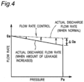
- Fig. 4 is a diagram for explaining correction of the flow rate set value Qa by the correction unit 27. If the hydraulic oil leaks in the hydraulic pump 12, the actual discharge flow rate, when the rotational frequency of the hydraulic pump 12 is held constant in the flow rate control, decreases as the discharge pressure increases, as shown in Fig. 4 . When the hydraulic oil in the hydraulic pump 12 leaks, the correction unit 27 of the present embodiment suppresses a deviation of the actual discharge flow rate from the flow rate set value Qa by adjusting the flow rate set value Qa in the flow rate control.
- the correction unit 27 corrects the flow rate set value Qa based on the discharge pressure of the hydraulic pump 12 input from the pressure sensor 16 and the rotational frequency of the motor 13 detected by the speed detector 22.
- the rotational frequency of the hydraulic pump 12 is controlled to a normal rotational frequency Na such that the discharge pressure of the hydraulic pump 12 in the pressure holding state becomes the pressure set value Pa, as shown by, for example, the point A in Fig. 3 .
- the normal rotational frequency Na of the present embodiment is experimentally obtained when the hydraulic circuit 10 is normal.
- the first determination rotational frequency N1 is set to be higher than the normal rotational frequency Na by a predetermined rotational frequency.
- the second determination rotational frequency N2 is set to be lower than the normal rotational frequency Na by a predetermined rotational frequency.
- the correction unit 27 of the present embodiment corrects the flow rate set value Qa depending on a change of the rotational frequency from the normal rotational frequency Na. Even if the hydraulic oil in the hydraulic pump 12 leaks as shown in Fig. 4 , the correction unit 27 corrects the flow rate set value Qa such that the actual discharge flow rate is held at a predetermined flow rate in the flow rate control. Specifically, if the hydraulic oil in the hydraulic pump 12 leaks, the correction unit 27 corrects the flow rate set value Qa so as to increase by ⁇ Qa according to the pressure of the hydraulic pump 12 in the flow rate control. As a result, the rotational frequency of the hydraulic pump 12 increases and the actual discharge flow rate increases, so that an influence of the leakage of the hydraulic oil in the hydraulic pump 12 on the P-Q characteristic of the hydraulic unit 1 is suppressed.
- the control device 20 determines by the rotational frequency of the pump 12 whether the hydraulic circuit 10 is abnormal or not, while the valve 15 is blocking the flow of the hydraulic oil in the discharge flow path 14 that fluidly connects the discharge side of the hydraulic pump 12 and the hydraulic actuator 2a.
- the hydraulic pump 12 is fluidly blocked from the hydraulic actuator 2a, so that the abnormality of the hydraulic circuit 10 can be identified from a change in the rotational frequency of the hydraulic pump 12 in the pressure holding state.
- the increase in the rotational frequency of the hydraulic pump 12 in the pressure holding state is caused by the leakage of the hydraulic oil in the hydraulic pump 12. Therefore, when determining that the hydraulic circuit 10 is abnormal based on the rotational frequency of the hydraulic pump 12 in the pressure holding state exceeding the predetermined first determination rotational frequency N1, the abnormality determination unit 25 can identify that the hydraulic oil leaks in the hydraulic pump 12.
- the abnormality determination unit 25 of the present embodiment determines that the hydraulic circuit 10 or any one of the hydraulic circuits of the main machine 2 is abnormal. In this case, the abnormality determination unit 25 of the present embodiment determines whether the hydraulic circuit 10 in the pressure holding state is abnormal or not. When the determination result indicates that the hydraulic circuit 10 is abnormal, it can be identified that the hydraulic oil leaks in the hydraulic pump 12.
- the hydraulic unit 1 includes the leakage flow path 17 that fluidly connects the flow path portion 14a of the discharge flow path 14 and the hydraulic oil tank 11, so that a part of the fluid discharged from the hydraulic pump 12 flows into the hydraulic oil tank 11 through the leakage flow path 17.
- the discharge flow rate of the hydraulic pump 12 becomes larger than the flow rate required for the hydraulic actuator 2a, and the hydraulic pump 12 is operated at a higher rotational frequency than when the leakage flow path 17 is not included.
- the drive torque of the hydraulic pump 12 is improved in stability, and stable pressure control/flow rate control can be performed.
- the decrease in the rotational frequency of the hydraulic pump 12 in the pressure holding state is caused by clogging of the leakage flow path 17. Therefore, when determining that the hydraulic circuit 10 is abnormal based on the rotational frequency of the hydraulic pump 12 in the pressure holding state becoming less than the predetermined second determination rotational frequency N2, the abnormality determination unit 25 can identify that there is clogging in the leakage flow path 17.
- the abnormality determination unit 25 of the present embodiment determines that the hydraulic circuit 10 or any one of the hydraulic circuits of the main machine 2 is abnormal. In this case, the abnormality determination unit 25 of the present embodiment determines whether the hydraulic circuit 10 in the pressure holding state is abnormal or not. When the determination result indicates that the hydraulic circuit 10 is abnormal, the abnormality determination unit 25 can identify that there is clogging in the leakage flow path 17.
- the abnormality determination unit 25 determines that the hydraulic circuit of the main machine 2 is abnormal.
- the rotational frequency of the hydraulic pump 12 in the state in which the hydraulic pump 12 is controlled to hold the discharge pressure detected by the pressure sensor 16 at a predetermined pressure while the valve 15 is not blocking the flow of the hydraulic oil in the discharge flow path 14, it can be identified which of the hydraulic unit 1 and the main machine 2 causes the change.
- the control device 20 determines the state of the hydraulic circuit 10 in the abnormality determination unit 25 when the monitor signal indicates that the operating state of the valve 15 is blocking the flow of the hydraulic oil in the discharge flow path 14. As a result, the control device 20 determines whether the hydraulic circuit 10 is abnormal or not while the valve 15 is reliably blocking the flow of the hydraulic oil, so that the determination can be improved in reliability.
- the correction unit 27 corrects the flow rate set value Qa such that when the hydraulic oil leaks in the hydraulic pump 12, the actual discharge flow rate is held at a predetermined flow rate in the flow rate control.
- the hydraulic pump 12 can supply the hydraulic oil at a desired flow rate to the hydraulic actuator 2a, so that a decrease in the performance of the hydraulic actuator 2a can be suppressed.
- a shut-off valve with less leakage than other valves is used as the valve 15, so that the determination of the abnormality of the hydraulic circuit 10 by the control device 20 can be improved in reliability.
- the abnormality determination unit 25 determines the state of the hydraulic circuit 10 based on the rotational frequency of the hydraulic pump 12, but may determine the state based on the discharge flow rate of the hydraulic pump 12 calculated from the rotational frequency of the hydraulic pump 12. Specifically, when the discharge flow rate of the hydraulic pump 12 calculated from the rotational frequency of the hydraulic pump 12 exceeds a predetermined first determination discharge flow rate Q1 corresponding to the first determination rotational frequency N1 in the pressure holding state, the abnormality determination unit 25 determines that the hydraulic circuit 10 is abnormal.
- the abnormality determination unit 25 determines that the hydraulic circuit 10 is abnormal.
- the first determination discharge flow rate Q1 is set to be larger than a normal discharge flow rate Qb corresponding to the normal rotational frequency Na by a predetermined flow rate.
- the second determination discharge flow rate Q2 is set to be less than the normal discharge flow rate Qb corresponding to the normal rotational frequency Na by a predetermined flow rate.
- Fig. 5 is a circuit diagram showing a configuration of the hydraulic unit 1 according to a first modification of the first embodiment.
- the flow rate control valve 19 of the hydraulic unit 1 according to the first modification is a flow rate adjustment valve.
- the first modification exhibits the same operational effects as those of the first embodiment.
- Fig. 6 is a circuit diagram showing a configuration of the hydraulic unit 1 according to a second modification of the first embodiment.
- the hydraulic circuit 10 of the hydraulic unit 1 according to the second modification does not include the leakage flow path.
- the second modification exhibits the same operational effects as those of the first embodiment.
- the hydraulic unit 1 of a second embodiment has the same configuration as that of the first embodiment except that a current sensor for measuring a motor current t of the motor 13 is provided, and the description of the first embodiment referring to Figs. 1 to 4 is applied to the second embodiment.
- components similar to those of the first embodiment will be denoted by the same reference signs, and detailed description thereof will be omitted.
- the motor 13 of the present embodiment is provided with a current sensor (e.g., a clamp meter) (not shown) that measures the motor current of the motor 13.
- a current sensor e.g., a clamp meter
- the current sensor according to the present embodiment is an example of the motor detector according to the present disclosure.
- a motor current of the motor 13 detected by the current sensor is input in addition to the discharge pressure detected by the pressure sensor 16 and the rotational frequency of the motor 13 detected by the speed detector 22.
- the abnormality determination unit 25 of the present embodiment determines whether the hydraulic circuit 10 is abnormal or not from the load state of the motor 13 in addition to the determination of the abnormality of the hydraulic circuit 10 based on the rotational frequency of the hydraulic pump 12. Specifically, the abnormality determination unit 25 of the present embodiment determines whether the hydraulic circuit 10 is abnormal or not from the motor current of the motor 13 in addition to the determination of the abnormality of the hydraulic circuit 10 based on the rotational frequency of the hydraulic pump 12.
- the abnormality determination unit 25 determines that the hydraulic circuit 10 is abnormal.
- the hydraulic unit 1 of the second embodiment exhibits the same operational effects as those of the first embodiment.
- the abnormality of the hydraulic circuit 10 is determined from the motor current of the motor 13 in addition to the determination of the abnormality of the hydraulic circuit 10 based on the rotational frequency of the hydraulic pump 12, so that the determination of the abnormality of the hydraulic circuit 10 can be improved in accuracy.
- the abnormality of the hydraulic circuit 10 is determined by using the motor current of the motor 13, but instead of the motor current of the motor 13, the abnormality of the hydraulic circuit 10 may be determined by using the winding temperature of the motor 13.
- the motor 13 is provided with a temperature thermistor (not shown) that detects the winding temperature of the motor 13.
- the abnormality determination unit 25 determined that the hydraulic circuit 10 is abnormal.
- the temperature thermistor according to the present embodiment is the motor detector according to the present disclosure.
- the winding temperature of the motor 13 is directly measured, so that the configuration is effective especially when the main machine 2 to which the hydraulic unit 1 is to be attached is a machine (e.g., an injection molding machine) that is frequently accelerated and decelerated.
- a machine e.g., an injection molding machine
- a hydraulic unit 101 of a third embodiment has the same configuration as the hydraulic unit 1 of the first embodiment except that a hydraulic pump 112 is a variable displacement pump, and the description of the first embodiment referring to Fig. 2 is applied to the third embodiment.
- a hydraulic pump 112 is a variable displacement pump
- the description of the first embodiment referring to Fig. 2 is applied to the third embodiment.
- components similar to those of the second embodiment will be denoted by the same reference signs, and detailed description thereof will be omitted.
- Fig. 7 is a circuit diagram showing the configuration of the hydraulic unit 101 according to the third embodiment.
- the hydraulic pump 112 of the hydraulic unit 101 of the present embodiment is a variable displacement pump.
- the hydraulic pump 112 of the present embodiment has a built-in flow rate sensor (not shown) for detecting the discharge flow rate of the hydraulic pump 112.
- the hydraulic pump 112 may be configured such that the discharge flow rate can be mechanically controlled according to a load pressure.
- the variable displacement mechanism of the hydraulic pump 112 is controlled or the rotational frequency of the motor 13 (rotational frequency of the hydraulic pump 12) is controlled such that the discharge flow rate of the hydraulic pump 112 becomes the flow rate set value Qa,.
- the discharge flow rate of the hydraulic pump 112 is detected by the flow rate sensor built in the hydraulic pump 112, or calculated by the product of the pump displacement (discharge flow amount per revolution) set by a discharge flow rate adjustment screw or the like and the rotational frequency of the motor 13.
- the discharge pressure of the hydraulic pump 112 is controlled by the variable displacement mechanism of the hydraulic pump 112 such that the discharge pressure becomes the pressure set value Pa, and the rotational frequency of the motor 13 (rotational frequency of the hydraulic pump 12) is controlled to be reduced in order to reduce power consumption after the pressure is stabilized.
- Fig. 8 is a diagram for explaining the determination of the state of the hydraulic circuit 10 by the abnormality determination unit 25 of the present embodiment.
- the vertical axis represents the discharge flow rate of the hydraulic pump 112 detected by the flow rate sensor or calculated by the product of the pump displacement set by a discharge flow rate adjustment screw or the like and the rotational frequency of the motor 13.
- the horizontal axis represents the discharge pressure of the hydraulic pump 112.
- the abnormality determination unit 25 determines in the pressure holding state whether the hydraulic circuit 10 is abnormal or not. Specifically, when the discharge flow rate of the hydraulic pump 112 detected by the flow rate sensor exceeds the predetermined first determination discharge flow rate Q1 in the pressure holding state, as shown in Fig. 8 , the abnormality determination unit 25 of the present embodiment determines in the pressure holding state that the hydraulic circuit 10 is abnormal.
- the notification unit 26 When it is determined by the abnormality determination unit 25 that the hydraulic circuit 10 is abnormal, the notification unit 26 notifies the abnormality of the hydraulic circuit 10.
- the abnormality determination unit 25 of the present embodiment determines in the pressure holding state that the hydraulic circuit 10 is abnormal.
- the third embodiment exhibits the same operational effects as those of the first embodiment.
- the hydraulic pump 112 is a variable displacement pump, but the pump is not limited thereto.
- the hydraulic pump 112 may be a fixed displacement pump with a built-in flow rate sensor.
- the motor 13 is an IPM motor, but the motor 13 is not limited thereto and may be a servomotor.
- the hydraulic unit includes a servo amplifier for driving the motor 13 instead of the inverter 24.
- valve according to the present disclosure is a shut-off valve, but the valve is not limited thereto and may be a valve having another configuration.
- the control device 20 controls the valve 15, but the control device is not limited thereto.
- a host control device e.g., a programmable logic controller (PLC) of a machine tool, a press machine, or the like to which the hydraulic unit is attached
- PLC programmable logic controller
- a signal that controls the valve may be input to both the valve and the control device from the host control device, or a monitor signal indicating the operating state of the valve may be input to the control device.
- the control device can determine whether the hydraulic circuit is abnormal or not.
Landscapes
- Engineering & Computer Science (AREA)
- Physics & Mathematics (AREA)
- Fluid Mechanics (AREA)
- General Engineering & Computer Science (AREA)
- Mechanical Engineering (AREA)
- Analytical Chemistry (AREA)
- Chemical & Material Sciences (AREA)
- Mining & Mineral Resources (AREA)
- Civil Engineering (AREA)
- Structural Engineering (AREA)
- Fluid-Pressure Circuits (AREA)
- Control Of Positive-Displacement Pumps (AREA)
- Control Of Transmission Device (AREA)
Claims (7)
- Unité hydraulique (1,101) comprenant :un circuit hydraulique (10) pouvant être en communication fluidique avec un actionneur hydraulique (2a) ; etun dispositif de commande (20) configuré pour commander le circuit hydraulique (10),le circuit hydraulique (10) comprenant :un réservoir d'huile hydraulique (11) configuré pour stocker de l'huile hydraulique ;une pompe hydraulique (12,112) configurée pour introduire l'huile hydraulique provenant du réservoir d'huile hydraulique (11) dans l'actionneur hydraulique (2a) ;un chemin d'évacuation (14) en communication fluidique avec un côté d'évacuation de la pompe hydraulique (12,112), et pouvant être raccordé à l'actionneur hydraulique (2a) ;une soupape (15) configurée pour bloquer un débit d'huile hydraulique dans le chemin d'évacuation (14) ;une sonde de pression (16) configurée pour détecter une pression de l'huile hydraulique dans une partie (14a) de chemin d'écoulement entre la soupape (15) et la pompe hydraulique (12,112) du chemin de refoulement (14),de sorte que lorsqu'une fréquence de rotation de la pompe hydraulique (12,112) dépasse une fréquence de rotation de première détermination prédéterminée (N1) ou lorsqu'un débit de refoulement de la pompe hydraulique (12,112) dépasse un débit de refoulement de première détermination prédéterminé (Q1), dans un état de maintien de pression dans lequel la pompe hydraulique (12,112) est commandée afin que la pression détectée par la sonde de pression (16) soit maintenue à une pression prédéterminée alors que la soupape (15) bloque le débit d'huile hydraulique, le dispositif de commande (20) établit que le circuit hydraulique (10) est anormal.
- Unité hydraulique (1,101) selon la revendication 1, comprenant :
un chemin d'écoulement de fuite (17) raccordant en communication fluidique la partie (14a) de chemin d'écoulement du chemin de refoulement (14) au réservoir d'huile hydraulique (11). - Unité hydraulique (1,101) selon la revendication 2, dans laquelle
lorsque la fréquence de rotation de la pompe hydraulique (12,112) devient inférieure à une fréquence de rotation de deuxième détermination prédéterminée (N2), inférieure à la fréquence de rotation de première détermination (N1), ou lorsque le débit de refoulement de la pompe hydraulique (12,112) devient inférieur à un débit de refoulement de deuxième détermination prédéterminé (Q2), inférieur à un débit de refoulement de première détermination (Q1), dans l'état de maintien de la pression, le dispositif de commande (20) établit que le circuit hydraulique (10) est anormal. - Unité hydraulique (1,101) selon une quelconque des revendications 1 à 3,
la soupape (15) étant configurée pour transmettre au dispositif de commande (20) un signal de contrôle indiquant un état opérationnel de la soupape (15). - Unité hydraulique (1,101) selon une quelconque des revendications 1 à 4, comprenant :un moteur (13) configuré pour entraîner la pompe hydraulique (12,112) ; etun détecteur de moteur configuré pour détecter un courant de moteur du moteur (13), ou une température d'enroulement du moteur,le dispositif de commande (20) établit, dans l'état de maintien de la pression, si le circuit hydraulique (10) est anormal, en fonction du courant de moteur du moteur (13), ou de la température d'enroulement du moteur, détectés par le détecteur de moteur.
- Unité hydraulique (1,101) selon une quelconque des revendications 1 à 5,le dispositif de commande (20) étant en mesure d'exécuter la régulation du débit, dans laquelle la fréquence de rotation de la pompe hydraulique (12,112) est régulée de sorte que la débit de refoulement de la pompe hydraulique (12,112) devienne une valeur de consigne du débit (Qa) ; etlors de la variation de la fréquence de rotation de la pompe hydraulique (12,112), dans l'état de maintien de la pression, relativement à une fréquence de rotation normale (Na) correspondant à la pression prédéterminée, le dispositif de commande (20) rectifie la valeur de consigne du débit (Qa) en fonction de la variation de la fréquence de rotation de la pompe hydraulique (12,112) relativement à la fréquence de rotation normale (Na).
- Unité hydraulique (1,101) selon une quelconque des revendications 1 à 6, la soupape (15) étant une soupape d'arrêt.
Applications Claiming Priority (2)
| Application Number | Priority Date | Filing Date | Title |
|---|---|---|---|
| JP2019168489A JP6922956B2 (ja) | 2019-09-17 | 2019-09-17 | 油圧ユニット |
| PCT/JP2020/033329 WO2021054124A1 (fr) | 2019-09-17 | 2020-09-02 | Unité hydraulique |
Publications (3)
| Publication Number | Publication Date |
|---|---|
| EP4006362A1 EP4006362A1 (fr) | 2022-06-01 |
| EP4006362A4 EP4006362A4 (fr) | 2022-09-07 |
| EP4006362B1 true EP4006362B1 (fr) | 2023-11-08 |
Family
ID=74878108
Family Applications (1)
| Application Number | Title | Priority Date | Filing Date |
|---|---|---|---|
| EP20865653.8A Active EP4006362B1 (fr) | 2019-09-17 | 2020-09-02 | Unité hydraulique |
Country Status (7)
| Country | Link |
|---|---|
| US (1) | US11608612B2 (fr) |
| EP (1) | EP4006362B1 (fr) |
| JP (1) | JP6922956B2 (fr) |
| KR (1) | KR102411994B1 (fr) |
| CN (1) | CN114402141A (fr) |
| ES (1) | ES2969124T3 (fr) |
| WO (1) | WO2021054124A1 (fr) |
Families Citing this family (8)
| Publication number | Priority date | Publication date | Assignee | Title |
|---|---|---|---|---|
| EP4206480A1 (fr) * | 2021-12-22 | 2023-07-05 | Fluid Overland | Méthode de détection de fuites internes et externes pour un actionneur hydraulique |
| JP7617439B2 (ja) * | 2022-03-29 | 2025-01-20 | ダイキン工業株式会社 | 油圧ユニット |
| JP7464860B2 (ja) | 2022-03-29 | 2024-04-10 | ダイキン工業株式会社 | 油圧ユニット |
| GB2622048A (en) * | 2022-08-31 | 2024-03-06 | Caterpillar Inc | Method for monitoring operation of a hydraulic system |
| JP7863028B2 (ja) * | 2022-10-31 | 2026-05-20 | 川崎重工業株式会社 | 液圧ポンプの性能低下検知システム |
| US12606994B2 (en) * | 2023-02-14 | 2026-04-21 | Cummins Inc. | Diagnostic system for monitoring a hydraulic system |
| DE102023202043B3 (de) * | 2023-03-07 | 2024-03-21 | Baumüller Nürnberg GmbH | Verfahren zum Betrieb eines Hydrauliksystems einer Industriemaschine |
| TWI851160B (zh) * | 2023-04-20 | 2024-08-01 | 台灣矽微電子股份有限公司 | 油壓迴路漏油偵測方法與裝置 |
Family Cites Families (6)
| Publication number | Priority date | Publication date | Assignee | Title |
|---|---|---|---|---|
| JP5109926B2 (ja) * | 2008-10-20 | 2012-12-26 | ダイキン工業株式会社 | 流体圧ユニット |
| JP5002715B2 (ja) * | 2010-04-06 | 2012-08-15 | 株式会社ユーテック | 油圧回路に用いる止弁 |
| JP5206766B2 (ja) * | 2010-11-02 | 2013-06-12 | ダイキン工業株式会社 | 油圧ユニット |
| JP2013253674A (ja) * | 2012-06-08 | 2013-12-19 | Daikin Industries Ltd | 流体圧ユニット |
| JP6712578B2 (ja) * | 2017-09-07 | 2020-06-24 | 日立建機株式会社 | 油圧駆動装置 |
| US11365828B2 (en) * | 2018-07-06 | 2022-06-21 | Danfoss Power Solutions Ii Technology A/S | System and method for detecting position of a valve driven by a solenoid linear actuator |
-
2019
- 2019-09-17 JP JP2019168489A patent/JP6922956B2/ja active Active
-
2020
- 2020-09-02 ES ES20865653T patent/ES2969124T3/es active Active
- 2020-09-02 KR KR1020227001102A patent/KR102411994B1/ko active Active
- 2020-09-02 EP EP20865653.8A patent/EP4006362B1/fr active Active
- 2020-09-02 WO PCT/JP2020/033329 patent/WO2021054124A1/fr not_active Ceased
- 2020-09-02 US US17/760,718 patent/US11608612B2/en active Active
- 2020-09-02 CN CN202080064820.0A patent/CN114402141A/zh active Pending
Also Published As
| Publication number | Publication date |
|---|---|
| KR102411994B1 (ko) | 2022-06-22 |
| CN114402141A (zh) | 2022-04-26 |
| JP2021046882A (ja) | 2021-03-25 |
| JP6922956B2 (ja) | 2021-08-18 |
| EP4006362A1 (fr) | 2022-06-01 |
| US20220333349A1 (en) | 2022-10-20 |
| US11608612B2 (en) | 2023-03-21 |
| WO2021054124A1 (fr) | 2021-03-25 |
| ES2969124T3 (es) | 2024-05-16 |
| EP4006362A4 (fr) | 2022-09-07 |
| KR20220009508A (ko) | 2022-01-24 |
Similar Documents
| Publication | Publication Date | Title |
|---|---|---|
| US11608612B2 (en) | Hydraulic unit | |
| KR102028372B1 (ko) | 압력식 유량 제어 장치 및 그 이상 검지 방법 | |
| JP6018159B2 (ja) | ポンプ、その動作のための方法およびコンピュータプログラム | |
| KR102087490B1 (ko) | 유체압 구동 장치 | |
| US20080131290A1 (en) | System and method for operation of a pump | |
| US20140314543A1 (en) | Compressor system and method of controlling the same | |
| CN100572823C (zh) | 由功率整流器供电的压缩机的操作方法 | |
| KR100984142B1 (ko) | 액압 구동 장치 | |
| KR20180036037A (ko) | 펌프 효율 산출방법 | |
| KR101639981B1 (ko) | 유체 정역학적 구동 시스템 그리고 유체 정역학적 구동 시스템을 작동하기 위한 방법 | |
| JP2000205140A (ja) | 圧縮機の予防保全方法及び装置 | |
| CN103629191A (zh) | 液压马达防堵转控制系统及防堵转方法、工程机械 | |
| JP2017025982A (ja) | サーボ駆動油圧ユニット | |
| US9429161B2 (en) | Method of controlling compressor system for preventing surge occurrence and compressor system using the same | |
| JP5382639B2 (ja) | 回転容積型ポンプの流量制御方法と同流量制御システム | |
| JP7553817B2 (ja) | 油圧ユニット及び油圧装置 | |
| CN113167060A (zh) | 使用入口压力的系统状态检测 | |
| JP2004212128A (ja) | 油圧装置の異常監視方法 | |
| CN113811745B (zh) | 燃气安全装置 | |
| JP2012149668A (ja) | 潤滑油供給排出装置 | |
| KR101659567B1 (ko) | 리크 진단 장치 및 방법 | |
| JP2022057405A (ja) | 油圧ユニットおよび油圧アクチュエータの診断方法 | |
| JP7376781B2 (ja) | 油圧ユニット | |
| KR101837984B1 (ko) | 압축기의 상선 오조립 검출방법 | |
| JP2015222791A (ja) | 送風機を備えるレーザ発振器 |
Legal Events
| Date | Code | Title | Description |
|---|---|---|---|
| STAA | Information on the status of an ep patent application or granted ep patent |
Free format text: STATUS: THE INTERNATIONAL PUBLICATION HAS BEEN MADE |
|
| PUAI | Public reference made under article 153(3) epc to a published international application that has entered the european phase |
Free format text: ORIGINAL CODE: 0009012 |
|
| STAA | Information on the status of an ep patent application or granted ep patent |
Free format text: STATUS: REQUEST FOR EXAMINATION WAS MADE |
|
| 17P | Request for examination filed |
Effective date: 20220225 |
|
| AK | Designated contracting states |
Kind code of ref document: A1 Designated state(s): AL AT BE BG CH CY CZ DE DK EE ES FI FR GB GR HR HU IE IS IT LI LT LU LV MC MK MT NL NO PL PT RO RS SE SI SK SM TR |
|
| A4 | Supplementary search report drawn up and despatched |
Effective date: 20220804 |
|
| RIC1 | Information provided on ipc code assigned before grant |
Ipc: F15B 19/00 20060101ALI20220729BHEP Ipc: F15B 20/00 20060101AFI20220729BHEP |
|
| DAV | Request for validation of the european patent (deleted) | ||
| DAX | Request for extension of the european patent (deleted) | ||
| RAP3 | Party data changed (applicant data changed or rights of an application transferred) |
Owner name: DAIKIN INDUSTRIES, LTD. |
|
| P01 | Opt-out of the competence of the unified patent court (upc) registered |
Effective date: 20230525 |
|
| GRAP | Despatch of communication of intention to grant a patent |
Free format text: ORIGINAL CODE: EPIDOSNIGR1 |
|
| STAA | Information on the status of an ep patent application or granted ep patent |
Free format text: STATUS: GRANT OF PATENT IS INTENDED |
|
| INTG | Intention to grant announced |
Effective date: 20230809 |
|
| GRAS | Grant fee paid |
Free format text: ORIGINAL CODE: EPIDOSNIGR3 |
|
| GRAA | (expected) grant |
Free format text: ORIGINAL CODE: 0009210 |
|
| STAA | Information on the status of an ep patent application or granted ep patent |
Free format text: STATUS: THE PATENT HAS BEEN GRANTED |
|
| AK | Designated contracting states |
Kind code of ref document: B1 Designated state(s): AL AT BE BG CH CY CZ DE DK EE ES FI FR GB GR HR HU IE IS IT LI LT LU LV MC MK MT NL NO PL PT RO RS SE SI SK SM TR |
|
| REG | Reference to a national code |
Ref country code: GB Ref legal event code: FG4D |
|
| REG | Reference to a national code |
Ref country code: CH Ref legal event code: EP |
|
| REG | Reference to a national code |
Ref country code: DE Ref legal event code: R096 Ref document number: 602020020877 Country of ref document: DE |
|
| REG | Reference to a national code |
Ref country code: IE Ref legal event code: FG4D |
|
| REG | Reference to a national code |
Ref country code: LT Ref legal event code: MG9D |
|
| REG | Reference to a national code |
Ref country code: NL Ref legal event code: MP Effective date: 20231108 |
|
| PG25 | Lapsed in a contracting state [announced via postgrant information from national office to epo] |
Ref country code: GR Free format text: LAPSE BECAUSE OF FAILURE TO SUBMIT A TRANSLATION OF THE DESCRIPTION OR TO PAY THE FEE WITHIN THE PRESCRIBED TIME-LIMIT Effective date: 20240209 |
|
| PG25 | Lapsed in a contracting state [announced via postgrant information from national office to epo] |
Ref country code: IS Free format text: LAPSE BECAUSE OF FAILURE TO SUBMIT A TRANSLATION OF THE DESCRIPTION OR TO PAY THE FEE WITHIN THE PRESCRIBED TIME-LIMIT Effective date: 20240308 |
|
| PG25 | Lapsed in a contracting state [announced via postgrant information from national office to epo] |
Ref country code: LT Free format text: LAPSE BECAUSE OF FAILURE TO SUBMIT A TRANSLATION OF THE DESCRIPTION OR TO PAY THE FEE WITHIN THE PRESCRIBED TIME-LIMIT Effective date: 20231108 |
|
| REG | Reference to a national code |
Ref country code: AT Ref legal event code: MK05 Ref document number: 1629841 Country of ref document: AT Kind code of ref document: T Effective date: 20231108 |
|
| PG25 | Lapsed in a contracting state [announced via postgrant information from national office to epo] |
Ref country code: NL Free format text: LAPSE BECAUSE OF FAILURE TO SUBMIT A TRANSLATION OF THE DESCRIPTION OR TO PAY THE FEE WITHIN THE PRESCRIBED TIME-LIMIT Effective date: 20231108 |
|
| PG25 | Lapsed in a contracting state [announced via postgrant information from national office to epo] |
Ref country code: AT Free format text: LAPSE BECAUSE OF FAILURE TO SUBMIT A TRANSLATION OF THE DESCRIPTION OR TO PAY THE FEE WITHIN THE PRESCRIBED TIME-LIMIT Effective date: 20231108 |
|
| PG25 | Lapsed in a contracting state [announced via postgrant information from national office to epo] |
Ref country code: NL Free format text: LAPSE BECAUSE OF FAILURE TO SUBMIT A TRANSLATION OF THE DESCRIPTION OR TO PAY THE FEE WITHIN THE PRESCRIBED TIME-LIMIT Effective date: 20231108 Ref country code: LT Free format text: LAPSE BECAUSE OF FAILURE TO SUBMIT A TRANSLATION OF THE DESCRIPTION OR TO PAY THE FEE WITHIN THE PRESCRIBED TIME-LIMIT Effective date: 20231108 Ref country code: IS Free format text: LAPSE BECAUSE OF FAILURE TO SUBMIT A TRANSLATION OF THE DESCRIPTION OR TO PAY THE FEE WITHIN THE PRESCRIBED TIME-LIMIT Effective date: 20240308 Ref country code: GR Free format text: LAPSE BECAUSE OF FAILURE TO SUBMIT A TRANSLATION OF THE DESCRIPTION OR TO PAY THE FEE WITHIN THE PRESCRIBED TIME-LIMIT Effective date: 20240209 Ref country code: BG Free format text: LAPSE BECAUSE OF FAILURE TO SUBMIT A TRANSLATION OF THE DESCRIPTION OR TO PAY THE FEE WITHIN THE PRESCRIBED TIME-LIMIT Effective date: 20240208 Ref country code: AT Free format text: LAPSE BECAUSE OF FAILURE TO SUBMIT A TRANSLATION OF THE DESCRIPTION OR TO PAY THE FEE WITHIN THE PRESCRIBED TIME-LIMIT Effective date: 20231108 Ref country code: PT Free format text: LAPSE BECAUSE OF FAILURE TO SUBMIT A TRANSLATION OF THE DESCRIPTION OR TO PAY THE FEE WITHIN THE PRESCRIBED TIME-LIMIT Effective date: 20240308 |
|
| REG | Reference to a national code |
Ref country code: ES Ref legal event code: FG2A Ref document number: 2969124 Country of ref document: ES Kind code of ref document: T3 Effective date: 20240516 |
|
| PG25 | Lapsed in a contracting state [announced via postgrant information from national office to epo] |
Ref country code: SE Free format text: LAPSE BECAUSE OF FAILURE TO SUBMIT A TRANSLATION OF THE DESCRIPTION OR TO PAY THE FEE WITHIN THE PRESCRIBED TIME-LIMIT Effective date: 20231108 Ref country code: RS Free format text: LAPSE BECAUSE OF FAILURE TO SUBMIT A TRANSLATION OF THE DESCRIPTION OR TO PAY THE FEE WITHIN THE PRESCRIBED TIME-LIMIT Effective date: 20231108 Ref country code: PL Free format text: LAPSE BECAUSE OF FAILURE TO SUBMIT A TRANSLATION OF THE DESCRIPTION OR TO PAY THE FEE WITHIN THE PRESCRIBED TIME-LIMIT Effective date: 20231108 Ref country code: NO Free format text: LAPSE BECAUSE OF FAILURE TO SUBMIT A TRANSLATION OF THE DESCRIPTION OR TO PAY THE FEE WITHIN THE PRESCRIBED TIME-LIMIT Effective date: 20240208 Ref country code: LV Free format text: LAPSE BECAUSE OF FAILURE TO SUBMIT A TRANSLATION OF THE DESCRIPTION OR TO PAY THE FEE WITHIN THE PRESCRIBED TIME-LIMIT Effective date: 20231108 Ref country code: HR Free format text: LAPSE BECAUSE OF FAILURE TO SUBMIT A TRANSLATION OF THE DESCRIPTION OR TO PAY THE FEE WITHIN THE PRESCRIBED TIME-LIMIT Effective date: 20231108 |
|
| PG25 | Lapsed in a contracting state [announced via postgrant information from national office to epo] |
Ref country code: DK Free format text: LAPSE BECAUSE OF FAILURE TO SUBMIT A TRANSLATION OF THE DESCRIPTION OR TO PAY THE FEE WITHIN THE PRESCRIBED TIME-LIMIT Effective date: 20231108 |
|
| PG25 | Lapsed in a contracting state [announced via postgrant information from national office to epo] |
Ref country code: CZ Free format text: LAPSE BECAUSE OF FAILURE TO SUBMIT A TRANSLATION OF THE DESCRIPTION OR TO PAY THE FEE WITHIN THE PRESCRIBED TIME-LIMIT Effective date: 20231108 |
|
| PG25 | Lapsed in a contracting state [announced via postgrant information from national office to epo] |
Ref country code: SK Free format text: LAPSE BECAUSE OF FAILURE TO SUBMIT A TRANSLATION OF THE DESCRIPTION OR TO PAY THE FEE WITHIN THE PRESCRIBED TIME-LIMIT Effective date: 20231108 |
|
| PG25 | Lapsed in a contracting state [announced via postgrant information from national office to epo] |
Ref country code: SM Free format text: LAPSE BECAUSE OF FAILURE TO SUBMIT A TRANSLATION OF THE DESCRIPTION OR TO PAY THE FEE WITHIN THE PRESCRIBED TIME-LIMIT Effective date: 20231108 Ref country code: SK Free format text: LAPSE BECAUSE OF FAILURE TO SUBMIT A TRANSLATION OF THE DESCRIPTION OR TO PAY THE FEE WITHIN THE PRESCRIBED TIME-LIMIT Effective date: 20231108 Ref country code: RO Free format text: LAPSE BECAUSE OF FAILURE TO SUBMIT A TRANSLATION OF THE DESCRIPTION OR TO PAY THE FEE WITHIN THE PRESCRIBED TIME-LIMIT Effective date: 20231108 Ref country code: EE Free format text: LAPSE BECAUSE OF FAILURE TO SUBMIT A TRANSLATION OF THE DESCRIPTION OR TO PAY THE FEE WITHIN THE PRESCRIBED TIME-LIMIT Effective date: 20231108 Ref country code: DK Free format text: LAPSE BECAUSE OF FAILURE TO SUBMIT A TRANSLATION OF THE DESCRIPTION OR TO PAY THE FEE WITHIN THE PRESCRIBED TIME-LIMIT Effective date: 20231108 Ref country code: CZ Free format text: LAPSE BECAUSE OF FAILURE TO SUBMIT A TRANSLATION OF THE DESCRIPTION OR TO PAY THE FEE WITHIN THE PRESCRIBED TIME-LIMIT Effective date: 20231108 |
|
| REG | Reference to a national code |
Ref country code: DE Ref legal event code: R097 Ref document number: 602020020877 Country of ref document: DE |
|
| PLBE | No opposition filed within time limit |
Free format text: ORIGINAL CODE: 0009261 |
|
| STAA | Information on the status of an ep patent application or granted ep patent |
Free format text: STATUS: NO OPPOSITION FILED WITHIN TIME LIMIT |
|
| 26N | No opposition filed |
Effective date: 20240809 |
|
| PG25 | Lapsed in a contracting state [announced via postgrant information from national office to epo] |
Ref country code: SI Free format text: LAPSE BECAUSE OF FAILURE TO SUBMIT A TRANSLATION OF THE DESCRIPTION OR TO PAY THE FEE WITHIN THE PRESCRIBED TIME-LIMIT Effective date: 20231108 |
|
| PG25 | Lapsed in a contracting state [announced via postgrant information from national office to epo] |
Ref country code: SI Free format text: LAPSE BECAUSE OF FAILURE TO SUBMIT A TRANSLATION OF THE DESCRIPTION OR TO PAY THE FEE WITHIN THE PRESCRIBED TIME-LIMIT Effective date: 20231108 |
|
| PG25 | Lapsed in a contracting state [announced via postgrant information from national office to epo] |
Ref country code: MC Free format text: LAPSE BECAUSE OF FAILURE TO SUBMIT A TRANSLATION OF THE DESCRIPTION OR TO PAY THE FEE WITHIN THE PRESCRIBED TIME-LIMIT Effective date: 20231108 |
|
| REG | Reference to a national code |
Ref country code: CH Ref legal event code: PL |
|
| PG25 | Lapsed in a contracting state [announced via postgrant information from national office to epo] |
Ref country code: LU Free format text: LAPSE BECAUSE OF NON-PAYMENT OF DUE FEES Effective date: 20240902 |
|
| GBPC | Gb: european patent ceased through non-payment of renewal fee |
Effective date: 20240902 |
|
| PG25 | Lapsed in a contracting state [announced via postgrant information from national office to epo] |
Ref country code: GB Free format text: LAPSE BECAUSE OF NON-PAYMENT OF DUE FEES Effective date: 20240902 |
|
| REG | Reference to a national code |
Ref country code: BE Ref legal event code: MM Effective date: 20240930 |
|
| PG25 | Lapsed in a contracting state [announced via postgrant information from national office to epo] |
Ref country code: BE Free format text: LAPSE BECAUSE OF NON-PAYMENT OF DUE FEES Effective date: 20240930 |
|
| PG25 | Lapsed in a contracting state [announced via postgrant information from national office to epo] |
Ref country code: FR Free format text: LAPSE BECAUSE OF NON-PAYMENT OF DUE FEES Effective date: 20240930 |
|
| PG25 | Lapsed in a contracting state [announced via postgrant information from national office to epo] |
Ref country code: CH Free format text: LAPSE BECAUSE OF NON-PAYMENT OF DUE FEES Effective date: 20240930 |
|
| PG25 | Lapsed in a contracting state [announced via postgrant information from national office to epo] |
Ref country code: IE Free format text: LAPSE BECAUSE OF NON-PAYMENT OF DUE FEES Effective date: 20240902 |
|
| PG25 | Lapsed in a contracting state [announced via postgrant information from national office to epo] |
Ref country code: FI Free format text: LAPSE BECAUSE OF FAILURE TO SUBMIT A TRANSLATION OF THE DESCRIPTION OR TO PAY THE FEE WITHIN THE PRESCRIBED TIME-LIMIT Effective date: 20231108 |
|
| PGFP | Annual fee paid to national office [announced via postgrant information from national office to epo] |
Ref country code: DE Payment date: 20250919 Year of fee payment: 6 |
|
| PGFP | Annual fee paid to national office [announced via postgrant information from national office to epo] |
Ref country code: IT Payment date: 20250923 Year of fee payment: 6 |
|
| PG25 | Lapsed in a contracting state [announced via postgrant information from national office to epo] |
Ref country code: CY Free format text: LAPSE BECAUSE OF FAILURE TO SUBMIT A TRANSLATION OF THE DESCRIPTION OR TO PAY THE FEE WITHIN THE PRESCRIBED TIME-LIMIT; INVALID AB INITIO Effective date: 20200902 |
|
| PGFP | Annual fee paid to national office [announced via postgrant information from national office to epo] |
Ref country code: ES Payment date: 20251030 Year of fee payment: 6 |
|
| PG25 | Lapsed in a contracting state [announced via postgrant information from national office to epo] |
Ref country code: HU Free format text: LAPSE BECAUSE OF FAILURE TO SUBMIT A TRANSLATION OF THE DESCRIPTION OR TO PAY THE FEE WITHIN THE PRESCRIBED TIME-LIMIT; INVALID AB INITIO Effective date: 20200902 |
|
| PG25 | Lapsed in a contracting state [announced via postgrant information from national office to epo] |
Ref country code: TR Free format text: LAPSE BECAUSE OF FAILURE TO SUBMIT A TRANSLATION OF THE DESCRIPTION OR TO PAY THE FEE WITHIN THE PRESCRIBED TIME-LIMIT Effective date: 20231108 |