EP4006434B1 - In einem partitionierungsmodus steuerbare saubere werkstatt - Google Patents
In einem partitionierungsmodus steuerbare saubere werkstatt Download PDFInfo
- Publication number
- EP4006434B1 EP4006434B1 EP20844025.5A EP20844025A EP4006434B1 EP 4006434 B1 EP4006434 B1 EP 4006434B1 EP 20844025 A EP20844025 A EP 20844025A EP 4006434 B1 EP4006434 B1 EP 4006434B1
- Authority
- EP
- European Patent Office
- Prior art keywords
- partition
- partition wall
- clean
- independent
- return air
- Prior art date
- Legal status (The legal status is an assumption and is not a legal conclusion. Google has not performed a legal analysis and makes no representation as to the accuracy of the status listed.)
- Active
Links
Images




Classifications
-
- F—MECHANICAL ENGINEERING; LIGHTING; HEATING; WEAPONS; BLASTING
- F24—HEATING; RANGES; VENTILATING
- F24F—AIR-CONDITIONING; AIR-HUMIDIFICATION; VENTILATION; USE OF AIR CURRENTS FOR SCREENING
- F24F3/00—Air-conditioning systems in which conditioned primary air is supplied from one or more central stations to distributing units in the rooms or spaces where it may receive secondary treatment; Apparatus specially designed for such systems
- F24F3/12—Air-conditioning systems in which conditioned primary air is supplied from one or more central stations to distributing units in the rooms or spaces where it may receive secondary treatment; Apparatus specially designed for such systems characterised by the treatment of the air otherwise than by heating and cooling
- F24F3/16—Air-conditioning systems in which conditioned primary air is supplied from one or more central stations to distributing units in the rooms or spaces where it may receive secondary treatment; Apparatus specially designed for such systems characterised by the treatment of the air otherwise than by heating and cooling by purification, e.g. by filtering; by sterilisation; by ozonisation
- F24F3/167—Clean rooms, i.e. enclosed spaces in which a uniform flow of filtered air is distributed
-
- F—MECHANICAL ENGINEERING; LIGHTING; HEATING; WEAPONS; BLASTING
- F24—HEATING; RANGES; VENTILATING
- F24F—AIR-CONDITIONING; AIR-HUMIDIFICATION; VENTILATION; USE OF AIR CURRENTS FOR SCREENING
- F24F3/00—Air-conditioning systems in which conditioned primary air is supplied from one or more central stations to distributing units in the rooms or spaces where it may receive secondary treatment; Apparatus specially designed for such systems
- F24F3/12—Air-conditioning systems in which conditioned primary air is supplied from one or more central stations to distributing units in the rooms or spaces where it may receive secondary treatment; Apparatus specially designed for such systems characterised by the treatment of the air otherwise than by heating and cooling
- F24F3/16—Air-conditioning systems in which conditioned primary air is supplied from one or more central stations to distributing units in the rooms or spaces where it may receive secondary treatment; Apparatus specially designed for such systems characterised by the treatment of the air otherwise than by heating and cooling by purification, e.g. by filtering; by sterilisation; by ozonisation
-
- F—MECHANICAL ENGINEERING; LIGHTING; HEATING; WEAPONS; BLASTING
- F24—HEATING; RANGES; VENTILATING
- F24F—AIR-CONDITIONING; AIR-HUMIDIFICATION; VENTILATION; USE OF AIR CURRENTS FOR SCREENING
- F24F11/00—Control or safety arrangements
-
- F—MECHANICAL ENGINEERING; LIGHTING; HEATING; WEAPONS; BLASTING
- F24—HEATING; RANGES; VENTILATING
- F24F—AIR-CONDITIONING; AIR-HUMIDIFICATION; VENTILATION; USE OF AIR CURRENTS FOR SCREENING
- F24F11/00—Control or safety arrangements
- F24F11/0008—Control or safety arrangements for air-humidification
-
- F—MECHANICAL ENGINEERING; LIGHTING; HEATING; WEAPONS; BLASTING
- F24—HEATING; RANGES; VENTILATING
- F24F—AIR-CONDITIONING; AIR-HUMIDIFICATION; VENTILATION; USE OF AIR CURRENTS FOR SCREENING
- F24F11/00—Control or safety arrangements
- F24F11/70—Control systems characterised by their outputs; Constructional details thereof
- F24F11/72—Control systems characterised by their outputs; Constructional details thereof for controlling the supply of treated air, e.g. its pressure
-
- F—MECHANICAL ENGINEERING; LIGHTING; HEATING; WEAPONS; BLASTING
- F24—HEATING; RANGES; VENTILATING
- F24F—AIR-CONDITIONING; AIR-HUMIDIFICATION; VENTILATION; USE OF AIR CURRENTS FOR SCREENING
- F24F13/00—Details common to, or for air-conditioning, air-humidification, ventilation or use of air currents for screening
- F24F13/02—Ducting arrangements
- F24F13/0227—Ducting arrangements using parts of the building, e.g. air ducts inside the floor, walls or ceiling of a building
-
- F—MECHANICAL ENGINEERING; LIGHTING; HEATING; WEAPONS; BLASTING
- F24—HEATING; RANGES; VENTILATING
- F24F—AIR-CONDITIONING; AIR-HUMIDIFICATION; VENTILATION; USE OF AIR CURRENTS FOR SCREENING
- F24F6/00—Air-humidification, e.g. cooling by humidification
- F24F6/12—Air-humidification, e.g. cooling by humidification by forming water dispersions in the air
- F24F6/14—Air-humidification, e.g. cooling by humidification by forming water dispersions in the air using nozzles
-
- F—MECHANICAL ENGINEERING; LIGHTING; HEATING; WEAPONS; BLASTING
- F24—HEATING; RANGES; VENTILATING
- F24F—AIR-CONDITIONING; AIR-HUMIDIFICATION; VENTILATION; USE OF AIR CURRENTS FOR SCREENING
- F24F7/00—Ventilation
- F24F7/04—Ventilation with ducting systems, e.g. by double walls; with natural circulation
- F24F7/06—Ventilation with ducting systems, e.g. by double walls; with natural circulation with forced air circulation, e.g. by fan positioning of a ventilator in or against a conduit
- F24F7/10—Ventilation with ducting systems, e.g. by double walls; with natural circulation with forced air circulation, e.g. by fan positioning of a ventilator in or against a conduit with air supply, or exhaust, through perforated wall, floor or ceiling
-
- F—MECHANICAL ENGINEERING; LIGHTING; HEATING; WEAPONS; BLASTING
- F24—HEATING; RANGES; VENTILATING
- F24F—AIR-CONDITIONING; AIR-HUMIDIFICATION; VENTILATION; USE OF AIR CURRENTS FOR SCREENING
- F24F2110/00—Control inputs relating to air properties
- F24F2110/10—Temperature
-
- F—MECHANICAL ENGINEERING; LIGHTING; HEATING; WEAPONS; BLASTING
- F24—HEATING; RANGES; VENTILATING
- F24F—AIR-CONDITIONING; AIR-HUMIDIFICATION; VENTILATION; USE OF AIR CURRENTS FOR SCREENING
- F24F2110/00—Control inputs relating to air properties
- F24F2110/20—Humidity
Definitions
- the invention relates to the technical field of clean production workshops, in particular to a clean workshop capable of being controlled by partition.
- a Patent document ( US 2002/0068524 A1 ) discloses that a clean room has an equipment installation area where an apparatus for treating an object to be treated such as a semiconductor wafer is installed, a process area 4 where the object is loaded in or unloaded from the apparatus, and an operation area where operations of the apparatus are executed.
- the equipment installation area, the process area and the operation area are arranged horizontally in the above-stated order and separated by partitions. These areas are air-conditioned independently of one another.
- the clean room is thus capable of preventing contamination of the object and a running cost of chemical filters in the clean room is reduced.
- a Patent document JP410096332A discloses a problem to be solved: to provide a clean room which, in a semiconductor device manufacturing process, can completely prevent diffusion of chemical materials from a manufacturing device that uses the chemical materials and which can control air conditioning at low cost to meet the need for preventing chemical pollution when conveying or storing semiconductor wafers; and discloses a solution: a clean room 1 is divided into a plurality of areas whose air conditioning systems are independent of one another, and in a second clean room 1 b where a manufacturing device 6a leaking chemical materials is placed, a chemical filter is installed on a circulation duct 13 and an air conditioning method by which air from which chemical mist produced in a working zone 5 has been removed is circulated to a ceiling chamber 4 is adopted to prevent the diffusion of the chemical mist to the areas with different air conditioning systems.
- a first clean room 1 a where conveyors 7a, 7b and storage devices 8a, 8b or the like are installed, an air conditioning method by which chemical- free air is supplied locally to only the required areas is
- the invention is defined in claim 1 and provides a clean workshop capable of being controlled by partition.
- the dependent claims define preferred embodiments of the invention.
- Cleanliness, temperature, relative humidity, and VOC concentration of each process area may be controlled, so as to reduce energy consumption while guaranteeing normal operation of each process area.
- the technical solution is as follows.
- the invention provides a clean workshop capable of being controlled by partition, including a workshop body.
- the workshop body is internally provided with an upper technical interlayer, a lower technical interlayer, and a clean production layer located between the upper technical interlayer and the lower technical interlayer.
- the clean production layer is internally provided with a clean room and return air passageways configured to communicate the lower technical interlayer and the upper technical interlayer.
- the return air passageways include a first return air passageway located on one side of the clean room, and a second return air passageway located on the other side of the clean room.
- the workshop body is further internally provided with a partition wall component to separate the clean room into a first clean production area and a second clean production area independent of each other.
- the first clean production area and the second clean production area are each provided with an independent return air system;
- the clean production layer are further internally provided with an overhead waffle board, the clean room is disposed on the waffle board and comprises suspended ceilings on an upper portion and wall boards matched with the suspended ceilings, and dry cooling coils configured to cool circulating air are disposed between the lower technical interlayer and the first return air passageway as well as between the lower technical interlayer and the second return air passageway.
- the first clean production area is a material storage and transfer area
- the second clean production area is a process production area
- suspended ceilings of the material storage and transfer area and the process production area are each provided with a plurality of fan filter units.
- the material storage and transfer area is internally provided with a material storage rack group
- the partition wall component comprises partition wall boards located on two sides of the material storage rack group, a top of each of the partition wall boards extends to a top of the upper technical interlayer, and a bottom of each of the partition wall boards is connected with the waffle board.
- the material storage rack group comprises two rows of material storage racks, a gap between each row of material storage rack and an adjacent partition wall board forms a third return air passageway, the third return air passageway communicate with the upper technical interlayer, and a side wall of each row of material storage rack is provided with a plurality of fan filter units configured to suck in an airflow in the third return air passageway and deliver the airflow into the corresponding material storage racks.
- a material transfer area is formed between the two rows of material storage racks, and a bottom of each row of material storage rack is provided with an airflow passage communicating the material transfer area and the third return air passageway adjacent to the material transfer area.
- the lower technical interlayer is internally provided with a fresh air supply pipe, and an air outlet port of the fresh air supply pipe communicates with the third return air passageway.
- the fresh air supply pipe is provided with an electric regulating valve, and a temperature sensor is disposed in the material storage and transfer area or the third return air passageway.
- the clean workshop further comprises a control apparatus, and the control apparatus is in signal connection with the temperature sensor and the electric regulating valve, and is configured to control an opening degree of the electric regulating valve according to a temperature detected by the temperature sensor, so as to control an air supply volume of the fresh air supply pipe.
- the clean room is separated, by the partition wall component, into the first clean production area and the second clean production area independent of each other, the first clean production area and the second clean production area are each provided with the independent return air system, when the first clean production area and the second clean production area are in an operating state, air supply volumes can be controlled by the independent return air systems, circulation of an airflow is realized, and thus requirements of the first clean production area and the second clean production area for cleanliness, temperature, relative humidity and VOC concentration are guaranteed respectively.
- separately controlling the air supply volume of each clean production area can facilitate reduction of energy consumption, so as to reduce costs.
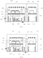
- a clean workshop capable of being controlled by partition disclosed by an embodiment includes a workshop body 270.
- the workshop body 270 is internally provided with a lower technical interlayer 110, an upper technical interlayer 100, and a clean production layer located between the upper technical interlayer 100 and the lower technical interlayer 110.
- the clean production layer is internally provided with a clean room.
- Two sides of the clean room are provided with a first return air passageway 130 and a second return air passageway 140 configured to communicate the upper technical interlayer 100 and the lower technical interlayer 110.
- the workshop body 270 is further internally provided with a partition wall component to separate the clean room into a first clean production area and a second clean production area independent of each other.
- the first clean production area and the second clean production area each have an independent return air system.
- the clean room is separated, by the partition wall component, into the first clean production area and the second clean production area independent of each other, the first clean production area and the second clean production area each have the independent return air system, when the first clean production area and the second clean production area are in an operating state, air supply volumes can be controlled by the independent return air systems, circulation of an airflow is realized, and thus requirements of the first clean production area and the second clean production area for cleanliness, temperature, relative humidity and VOC concentration are guaranteed respectively.
- separately controlling the air supply volume of each clean production area can facilitate reduction of energy consumption, so as to reduce costs.
- a traditional clean workshop includes a workshop body 270.
- the workshop body 270 is internally provided with an upper technical interlayer 100, a lower technical interlayer 110, and a clean production layer located between the upper technical interlayer 100 and the lower technical interlayer 110.
- the clean production layer is internally provided with an overhead waffle board 190 and a clean room 120 disposed on the waffle board 190.
- the clean room 120 includes raised floors 150 located on the waffle board 190, suspended ceilings 160, and wall boards matched with the raised floors 150 and the suspended ceilings 160.
- Two sides of the clean room 120 are provided with a first return air passageway 130 and a second return air passageway 140 configured to communicate the lower technical interlayer 110 and the upper technical interlayer 100.
- Dry cooling coils 220 configured to cool circulating air are disposed between the lower technical interlayer 110 and the first return air passageway 130 as well as between the lower technical interlayer 110 and the second return air passageway 140.
- the material storage area 171 is provided with material storage racks 230 configured to store materials such as glass substrates and chips to be processed.
- the material transfer area 172 is internally provided with an automatic conveying apparatus.
- Process production devices are usually arranged in the process production areas 125, and the process production areas 125 are also activity areas for operators. Since the glass substrates, chips, etc. to be processed in the material storage area 171 and the material transfer area 172 are in direct contact with ambient air, the air cleanliness level in this space is usually much stricter than the air cleanliness level in the process production areas 125.
- a plurality of fan filter units 210 are arranged on suspended ceilings 160 of the process production areas 125, and in order to ensure the strict cleanliness level of a material storage and transfer area 170, a suspended ceiling 160 of the material transfer area 172 is usually covered with fan filter units 210, and side faces of the material storage racks 230 are highly densely provided with fan filter units 210.
- An air circulation path of a whole purification air conditioning system of the clean room is shown as arrows in Fig. 1 .
- the suspended ceilings 160 of the process production areas 125 need to be additionally provided with fan filter units with the same air volume as the fan filter units installed on the side faces of the material storage racks 230, resulting in a large increase in the quantity of fan filter units 210 that need to be installed on the suspended ceilings 160 of the process production areas 125, and also resulting in an increase of energy consumption.
- the cleanliness level requirements of the material storage area 171 and the material transfer area 172 are very strict, the air supply volume ensuring the cleanliness level needs to be very large, but devices in these areas generate very little heat, so only a very few part of an air flow flowing through the areas needs to be cooled, but according to a traditional construction method of the clean room 120 shown in Fig. 1 , airflows sucked in by the fan filter units 210 installed at the top of the material transfer area 172 and installed on the side walls of the material storage racks 230 are both airflows processed by the dry cooling coils 220.
- the clean room in the clean room of this embodiment, is disposed on an overhead waffle board 190, and the clean room further includes suspended ceilings 160 on an upper portion and wall boards matched with the suspended ceilings 160.
- Dry cooling coils 220 configured to cool circulating air are disposed between a lower technical interlayer 110 and a first return air passageway 130 as well as between the lower technical interlayer 110 and a second return air passageway 140.
- the waffle board 190 is a concrete slab with evenly formed holes, and has supporting and ventilating functions.
- the clean room 120 includes the suspended ceilings 160 on the upper portions and the wall boards matched with the suspended ceilings 160.
- Two independent areas included by a first clean production area are process production areas 125.
- a space between the two process production areas 125 is a material storage and transfer area 170.
- Suspended ceilings of the material storage and transfer area 170 and the process production areas 125 are each provided with a plurality of fan filter units 210. As shown in Figs. 2 and 3 , two sides of the material storage and transfer area 170 are respectively provided with the process production areas 125.
- the material storage and transfer area 170 is internally provided with a material storage rack group, and two sides of the material storage rack group are each provided a partition wall board 200. A top of each partition wall board 200 extends to a top of the upper technical interlayer 100, and a bottom of each partition wall board 200 is connected with the waffle board 190.
- the material storage rack group includes two rows of material storage racks 230. A gap between each row of material storage rack 230 and an adjacent partition wall board 200 forms a third return air passageway 180, and each third return air passageway 180 communicates with the upper technical interlayer 100. Specifically, the third return air passageways 180 communicate with the upper technical interlayer 100 through holes formed in the suspended ceilings 160, and the holes formed in the suspended ceilings 160 are distributed in areas corresponding to the third return air passageways 180.
- the material storage racks 230 are configured to store materials such as glass substrates and chips to be processed. Areas where the material storage racks 230 are disposed are material storage areas 171. An area between the two rows of material storage racks 230 forms a material transfer area 172, and an automatic conveying apparatus is disposed in the material transfer area 172.
- a side wall of each row of material storage rack 230 is provided with a plurality of fan filter units 210 configured to suck in an airflow in the third return air passageways 180 and deliver the airflow into the corresponding material storage racks 230, that is, these fan filter units 210 may suck in the airflow entering the third return air passageways 180, and after filtering and pressuring the airflow, deliver the airflow to one side of each material storage rack 230, namely to the material storage areas 171, so as to dilute a concentration of suspended particles in the material storage areas 171 to maintain a cleanliness level requirement of the material storage areas 171.
- fan filter units 210 highly densely disposed at a top of the material transfer area 172 suck in an airflow in the upper technical interlayer 100, and after filtering and pressuring the airflow, deliver the airflow into the material transfer area 172, so as to dilute a concentration of suspended particles in the material transfer area 172 to maintain a cleanliness level requirement of the material transfer area 172.
- a bottom of each row of material storage rack 230 is provided with an airflow passage communicating the material transfer area 172 and each third return air passageway 180 adjacent to the material transfer area 172, that is, the third return air passageways 180 communicate with the material transfer area 172.
- a raised floor 150 is disposed between the bottom of each row of material storage rack 230 and the waffle board 190, and gaps between the raised floors 150 and the waffle board 190 form airflow passages.
- raised floors 150 may further be disposed on the waffle board 190, and the raised floors 150 are provided with holes, so as to ensure communication between the process production areas 125 and the lower technical interlayer 110.
- surfaces of the raised floors 150 are relatively flat, which facilitates arrangement of process production devices. Apparatuses such as pipes may further be arranged in the gaps between the raised floors 150 and the waffle board 190.
- the third return air passageways 180 communicate with the material transfer area 172 through the airflow passages at the bottoms of the material storage racks 230, and communicate with the lower technical interlayer 110 through the holes formed in the waffle board 190.
- One part of the airflow flowing out of the material transfer area 172 enters the third return air passageways 180 through the airflow passages at the bottoms of the material storage racks 230, and the other part enters the lower technical interlayer 110 through the holes in the waffle board 190.
- Most of the airflow entering the lower technical interlayer 110 also passes through, due to a path and pressure balance, the holes of the waffle board 190 to enter the third return air passageways 180, while a small part of the airflow enters a first return air passageway 130 and a second return air passageway 140 through the dry cooling coils 220.
- One part of an airflow in the third return air passageways 180 is sucked in by the fan filter units 210 disposed on the side walls of the material storage racks 230, is delivered out after being pressurized and filtered, and passes through the material storage racks 230 to enter the material transfer area 172.
- the other part of the airflow flows upwards into the upper technical interlayer 100, is sucked in by the fan filter units 210 disposed at the top of the material transfer area 172, and is delivered into the material transfer area 172 after being pressurized and filtered. It can be seen that after entering the third return air passageways 180, most of the airflow flowing out of the material transfer area 172 returns to the material transfer area 172 again through the fan filter units 210 disposed on the side walls of the material storage racks 230 and the fan filter units 210 arranged at the top of the material transfer area 172, which realizes local circulation.
- the quantity of the dry cooling coils 220 may be greatly reduced, and a space occupied by the first return air passageway 130, the second return air passageway 140 and the upper technical interlayer 100 may also be reduced, and the construction cost of the clean room 120 is reduced.
- the third return air passageways 180 provide an air volume for the fan filter units disposed on the side walls of the material storage racks 230, tops of the process production areas 125 do not need to be additionally provided with the fan filter units 210 with the same air volume as the fan filter units 210 installed on the side faces of the material storage racks 230, which reduces the air supply volume of the process production areas 125 and the quantity of the fan filter units 210, and reduces energy consumption and construction costs. It is worth noting that in the structure shown in Fig. 2 , the raised floors 150 may not be provided to reduce the construction costs.
- a fresh air supply pipe 240 is disposed in the lower technical interlayer 110, and an air outlet port of the fresh air supply pipe 240 communicates with each third return air passageway 180.
- the fresh air supply pipe 240 is configured to deliver processed low-temperature air into the third return air passageways 180.
- fresh air is mixed with a circulating air flow, and one part of a mixed airflow is sucked in by the fan filter units disposed on the side walls of the material storage racks, is delivered out after being pressurized and filtered, and passes through the material storage racks to enter the material transfer area.
- the fresh air supply pipe 240 may communicate with a fresh air processing unit of the clean room air conditioning system. Further, the fresh air supply pipe 240 is provided with an electric regulating valve 260, and a temperature sensor is disposed in the material storage and transfer area 170 or each third return air passageway 180.
- the electric regulating valve 260 and the temperature sensor are in signal connection with a control apparatus, and the control apparatus is configured to control an opening degree of the electric regulating valve 260 according to a temperature detected by the temperature sensor, so as to control an air supply volume of the fresh air supply pipe 240.
- the amount of fresh air delivered into the third return air passageways 180 may be controlled according to the temperature in the material storage and transfer area 170 or the third return air passageways 180, so as to accurately control temperatures of the material storage areas 171 and the material transfer area 172.
- a sealing plate 250 is disposed at a bottom of the waffle board 190 corresponding to the material storage and transfer area 170 and the third return air passageways 180, and the sealing plate 250 is configured to separate bottoms of the material storage and transfer area 170 and the third return air passageways 180 from the lower technical interlayer 110.
- a cover plate is disposed at tops of the holes in the waffle board corresponding to the material storage and transfer area and the return air passageways, and the cover plate is configured to separate the bottoms of the material storage and transfer area and the return air passageways from the lower technical interlayer, so that the material storage and transfer area and the third return air passageways 180 are completely separated from a surrounding environment, and an independent air circulation is formed between the material storage and transfer area and the third return air passageways 180.
- the airflow flowing out from the material transfer area 172 enters the third return air passageways 180 through the airflow passages formed by the raised floors 150 and the waffle board 190, and is mixed with fresh air delivered by the fresh air supply pipe 240.
- One part of a mixed airflow is sucked in by the fan filter units 210 disposed on the side walls of the material storage racks 230, is delivered out after being pressurized and filtered, and passes through the material storage racks 230 to enter the material transfer area 172.
- the other part of the mixed airflow flows upwards into the upper technical interlayer 100, is sucked in by the fan filter units 210 disposed at the top of the material transfer area 172, is delivered out after being pressurized and filtered, and enters the material transfer area 172, so as to form a circulation.
- a pressure value in the material storage and transfer area 170 is higher than a surrounding pressure value, which ensures a requirement that a pressure value in a strict cleanliness level area should be higher than a pressure value of a poor cleanliness level area. That is, because a pressure in the material storage and transfer area 170 is high, air in the space may enter the surrounding environment through gaps between the structures, and because air with a poor cleanliness level in the surrounding environment may not flow reversely, the strict cleanliness level in the material storage and transfer area is ensured.
- a partition board with a certain height may be vertically disposed downwards at a position, corresponding to each partition wall board, in the lower technical interlayer and attached to a lower bottom face of the waffle board, and a sealing plate is horizontally disposed at a lower end of each partition board.
- the vertically disposed partition boards and the horizontally disposed sealing plates are configured to separate the bottom of the material storage and transfer area from the outside, so as to form an independent air circulation between the material storage and transfer area and the return air passageway.
- the fresh air supply pipe may further be arranged to provide fresh air for the third return air passageways
- the sealing plate is disposed at the bottom of the waffle board corresponding to the material storage and transfer area and the third return air passageways
- the cover plate is disposed at the tops of the holes in the waffle board corresponding to the material storage and transfer area and the third return air passageways
- the partition boards with the certain height may be vertically disposed downwards at corresponding areas of the material storage and transfer area and the third return air passageways and are attached to the lower bottom face of the waffle board
- the sealing plates are horizontally disposed at the lower ends of the partition boards, so that the material storage and transfer area and the third return air passageways are separated from the surrounding environment, which further ensures the pressure, temperature and humidity requirements in the material storage and transfer area.
- the clean room with a secondary humidification system includes: at least one group of secondary humidification system.
- Each group of secondary humidification system includes: a humidification apparatus 280, disposed in the upper technical interlayer 100 of the clean room, the lower technical interlayer 110 of the clean room, the first return air passageway of the clean room, the second return air passageway of the clean room or the clean room; a relative humidity sensor 290, configured to detect the air humidity in the clean room; and a humidity controller 300 connected with the relative humidity sensor 290 and the humidification apparatus 280.
- the humidity controllers 300 are configured to receive a humidity signal of the relative humidity sensors 290 so as to control the humidification apparatuses 280 to operate according to the humidity signal.
- each group of secondary humidification system includes: the relative humidity sensor disposed in the clean room and configured to detect the indoor air humidity.
- the relative humidity sensors may be disposed in the production areas of the clean room.
- the production areas are places where production devices are placed.
- the humidity in the production areas may be detected by the relative humidity sensors disposed in the production areas, that is, the relative humidity of the production environment for a product is detected, so that the actual relative humidity of a manufacturing environment of the product may be more accurately determined.
- the humidification apparatuses are configured to directly humidify indoor air.
- the humidification apparatuses may be disposed in the upper technical interlayer of the clean room, or in the lower technical interlayer of the clean room, or in the first return air passageway or the second return air passageway of the clean room, or in the production area of the clean room.
- Humidified air may enter an air system in the clean room, so as to humidify the entire environment of the clean room.
- the humidified air may enter the production area during the circulation of the air system in the clean room, so that the production environment in the clean room gets an effect of secondary humidification.
- the humidity controllers are in signal connection with the relative humidity sensors, are electrically connected with the humidification apparatuses, and may receive the humidity signal detected by the relative humidity sensors and control the humidification apparatuses through the humidity signal.
- the humidity signal is a relative humidity value of the clean production area, and a preset value is set according to a requirement of the product produced in the production area for the relative humidity of the production area.
- the humidity controllers control the humidification apparatuses to operate to humidify the indoor air, and the humidification amount may be regulated in proportion.
- the humidity controllers control the humidification apparatuses to reduce the humidification amount in proportion to constant and continuous humidification or does not start working.
- the humidity controller control the humidification apparatuses to automatically humidify the indoor air by receiving the humidity signal from the relative humidity sensors, so as to meet the humidity requirements of the production environment in the production area, and the relative humidity of the production environment in the production area may reach the best value.
- a secondary humidification system is disposed in the clean room, which can effectively perform secondary humidification on the indoor air, and can increase the relative humidity of the environment in the production area, so that the relative humidity of the production environment of the product reaches the optimal value, which is conducive to ensuring a good production process and manufacturing environment, and improving the product yield.
- each group of secondary humidification system is internally provided with one or more relative humidity sensors.
- the humidity signal is an induction value of the relative humidity sensor; and when there are a plurality of relative humidity sensors in each group of secondary humidification system, the humidity signal is an average value of humidity induction values of the plurality of relative humidity sensors.
- the plurality of relative humidity sensors are provided, the average value of the induction values of the plurality of relative humidity sensors serves as the humidity signal, and the indoor relative humidity can be more accurately tested, which is beneficial to improving the accuracy of the secondary humidification systems for indoor humidification, and ensuring that the humidity of the indoor environment is the optimal relative humidity value of production.
- the clean room with the secondary humidification systems may be internally provided with a plurality of groups of secondary humidification systems, which is beneficial to improving the humidification rate of the production environment in the clean room, and making the environment humidity reach the relative humidity value required by the production environment more quickly.
- the humidification apparatuses 280 in the plurality of groups of secondary humidification systems may be disposed at any one, or two, or three, or four of the upper technical interlayer 100 of the clean room, the lower technical interlayer 110 of the clean room, the first return air passageway 130 of the clean room, the second return air passageway 140 of the clean room, or the clean room 120.
- the humidification apparatuses 280 in the plurality of groups of secondary humidification systems may all be disposed in the upper technical interlayer 100 of the clean room, or the return air passageways of the clean room, or the lower technical interlayer 110 of the clean room, or the clean room 120.
- part of the humidification apparatuses in the plurality of groups of humidification systems may be disposed in the upper technical interlayer 100, while another part of them may be disposed in the first return air passageway 130 and the second return air passageway 140.
- part of the humidification apparatuses in the plurality of groups of humidification systems are disposed in the lower technical interlayer 110, while another part of them are disposed in the first return air passageway 130 and the second return air passageway 140.
- part of the humidification apparatuses in the plurality of groups of humidification systems are disposed in the upper technical interlayer 100, while another part of them are disposed in the lower technical interlayer 110.
- part of the humidification apparatuses in the plurality of groups of humidification systems are disposed in the first return air passageway 130 and the second return air passageway 140, while another part of them are disposed in the clean room 120.
- part of the humidification apparatuses in the plurality of groups of humidification systems are disposed in the upper technical interlayer 100, while another part of them are disposed in the lower technical interlayer 110, and while further another part of them are disposed in the first return air passageway 130 and the second return air passageway 140, that is, the upper technical interlayer 100, the lower technical interlayer 110, the first return air passageway 130 and the second return air passageway 140 are all internally provided with the humidification apparatuses.
- There are a plurality of ways to arrange the humidification apparatuses in the secondary humidification systems in the upper technical interlayer 100, the lower technical interlayer 110, the first return air passageway 130, the second return air passageway 140 and the clean room 120 which are not listed here. It should be noted that the setting of each group of secondary humidification system in the plurality of groups of secondary humidification systems may be made according to actual needs, and the quantity of the secondary humidification systems may also be set according to indoor needs, which are not limited in the embodiment.
- the production workshop may be internally divided into a plurality of independent partitions within the production workshop according to the requirements for the production environment, special requirements for a preparation process, and the like. Products with different environment requirements are prepared or process manufacturing is conducted in the different independent partitions.
- the clean room may be internally provided with a first independent partition and a second independent partition according to different humidities, that is, the plurality of independent partitions include the first independent partition and the second independent partition.
- first independent partitions there may be a plurality of first independent partitions, there may also be a plurality of second independent partitions, and the quantity and layout of the first independent partitions and the second independent partitions may be set according to actual demands. Moreover, by arranging the first independent partition and the second independent partition in the clean room, there are also a plurality of options as below to set the secondary humidification systems.
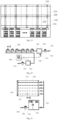
- a first independent partition 320 and a second independent partition 330 are disposed in the clean room, and a partition wall component is disposed between the first independent partition 320 and the second independent partition 330 to separate the clean room 120 into the first clean production area 121 and a second clean production area 122, to separate the upper technical interlayer 100 into a first upper technical interlayer 101 and a second upper technical interlayer 102, and to separate the lower technical interlayer 110 into a first lower technical interlayer 111 and a second lower technical interlayer 112.
- the first independent partition 320 includes the first upper technical interlayer 101, the first clean production area 121, the first lower technical interlayer 111 and the first return air passageway 130.
- the first return air passageway 130 is located on a side, facing away from the second independent partition 330, of the first independent partition 320.
- the second independent partition 330 includes the second upper technical interlayer 102, the second clean production area 122, the second lower technical interlayer 112 and the second return air passageway 140.
- the secondary humidification systems are arranged in the first independent partition 320, and may directly humidify air in the first independent partition, which effectively improves the indoor air humidity, especially the first independent partition, and is beneficial to ensuring that the relative humidity in the first independent partition is the optimal value required by production. There may be one group of secondary humidification system, or a plurality of groups of secondary humidification systems in the first independent partition, which is not limited in this embodiment.
- the partition wall component includes a partition wall 350 disposed between the first independent partition 320 and the second independent partition 330, that is, only one partition wall 350 is disposed between the first independent partition 320 and the second independent partition 330.
- the partition wall 350 corresponds to at least the first clean production area 121 and the second clean production area 122, and separates the first clean production area 121 from the second clean production area 122, that is, the first clean production area and the second clean production area are adjacent and next to each other, and are separated only by the partition wall.
- the bottom of the partition wall 350 may further be arranged to extend to the bottom plate of the lower technical interlayer and be in sealed fit with the bottom plate of the lower technical interlayer, at the same time, a top of the partition wall extends to a top plate of the upper technical interlayer and is in sealed fit with the top plate of the upper technical interlayer, that is, the first lower technical interlayer 111 and the second lower technical interlayer 112 are separated by the partition wall, and at the same time, the first upper technical interlayer 101 and the second upper technical interlayer 102 are also separated by the partition wall.
- the two independent partitions are completely separated, and by arranging the first independent partition and the second independent partition as independent spaces that do not communicate with each other, mutual environmental conditions may be prevented from affecting each other, which is more beneficial to ensuring respective environmental demands.
- the partition wall component includes two side-by-side partition walls, namely a first partition wall 590 and a second partition wall 600, disposed between the first independent partition 320 and the second independent partition 330, that is, the side-by-side and opposite first partition wall 590 and second partition wall 600 are disposed between the first independent partition 320 and the second independent partition 330.
- the two partition walls at least correspond to the first clean production area 121 and the second clean production area 122, and separate the first clean production area 121 from the second clean production area 122.
- the first partition wall 590 is located in the first independent partition 320
- the second partition wall 600 is located in the second independent partition 330
- a fourth return air passageway is formed between the first partition wall 590 and the second partition wall 600.
- the first partition wall and the second partition wall may only correspond to the first clean production area and the second clean production area
- the first upper technical interlayer communicates with the second upper technical interlayer
- the first lower technical interlayer communicates with the second lower technical interlayer.
- a bottom of the first partition wall may further be arranged to extend to the lower technical interlayer
- a bottom of the second partition wall may be arranged to extend to the lower technical interlayer.
- the partition wall component includes three side-by-side partition walls, namely the first partition wall 590, the second partition wall 600, and a third partition wall 610, between the first independent partition 320 and the second independent partition 330.
- the third partition wall 610 is located between the first partition wall 590 and the second partition wall 600.
- the first partition wall 590 is located in the first independent partition 320
- the second partition wall 600 is located in the second independent partition 330.
- a top of the third partition wall 610 extends to the top plate of the upper technical interlayer and is in sealed fit with the top plate of the upper technical interlayer, and a bottom of the third partition wall 610 extends to the bottom plate of the lower technical interlayer and is in sealed fit with the bottom plate of the lower technical interlayer.
- a fifth return air passageway 360 is formed between the first partition wall 590 and the third partition wall 610, or, a sixth return air passageway 370 is formed between the second partition wall 600 and the third partition wall 610.
- the fifth return air passageway 360 is formed between the first partition wall 590 and the third partition wall 610, and at the same time, the sixth return air passageway 370 is formed between the second partition wall 600 and the third partition wall 610.
- the mutual environmental conditions may be prevented from affecting each other, which is more beneficial to ensuring respective environmental demands.
- the first independent partition is internally provided with the secondary humidification systems, so that the production process with high relative humidity requirements may be performed in the first independent partition, or products with high relative humidity requirements may be produced in the first independent partition.
- the secondary humidification systems may increase the relative humidity value of the air in the first independent partition, so as to ensure that the relative humidity of the air in the first independent partition reaches the optimal demand value for product production, which is beneficial to improving the product yield.
- a humidification apparatus may be disposed in the fifth return air passageway 360 to facilitate humidification in the first independent partition.
- a production device 310 that produces volatile organic compounds in the operating process is disposed in the first clean production area 121 in the first independent partition 320.
- the first lower technical interlayer 111 is internally provided with a zeolite runner unit 340 configured to adsorb the volatile organic compounds.
- the zeolite runner unit 340 may dehumidify the indoor air to a certain extent in the operating process, resulting in a decrease in the environmental humidity of the clean room, especially the first independent partition, which deviates from the environmental humidity demand value for product production.
- the secondary humidification systems disposed in the first independent partition 320 may directly humidify the indoor air and improve the relative humidity of the indoor air, which is beneficial to ensuring that the relative humidity of the indoor air is maintained at the optimal humidity demand value for product production, and is beneficial to ensuring the product yield.
- the first independent partition 320 and the second independent partition 330 are disposed in the clean room, and the partition wall component is disposed between the first independent partition 320 and the second independent partition 330 to separate the production area into the first clean production area 121 and the second clean production area 122, to separate the upper technical interlayer 100 into the first upper technical interlayer 101 and the second upper technical interlayer 102, and to separate the lower technical interlayer 110 into the first lower technical interlayer 111 and the second lower technical interlayer 112.
- the first independent partition 320 includes the first upper technical interlayer 101, the first clean production area 121, the first lower technical interlayer 111 and the first return air passageway 130.
- the second independent partition 330 includes the second upper technical interlayer 102, the second clean production area 122, the second lower technical interlayer 112 and the second return air passageway 140.
- There are at least two groups of secondary humidification systems and the first independent partition 320 and the second independent partition 330 are both internally provided with the secondary humidification systems.
- There may be two groups of secondary humidification systems and the first independent partition 320 and the second independent partition 330 are each internally provided with one group of secondary humidification system.
- there may be a plurality of groups of secondary humidification systems and the first independent partition 320 and the second independent partition 330 are each internally provided with a plurality of groups of secondary humidification systems.
- the first independent partition and the second independent partition are both internally provided with the secondary humidification systems, so that the relative humidity of the air in the first independent partition and the relative humidity of the air in the second independent partition can be rapidly improved, which is beneficial to ensuring that the relative humidity of the air in the first independent partition and the relative humidity of the air in the second independent partition are at the optimal demand value, and ensuring the product yield.
- the partition wall component includes the partition wall 350 disposed between the first independent partition 320 and the second independent partition 330, that is, only one partition wall 350 is disposed between the first independent partition 320 and the second independent partition 330.
- the partition wall 350 corresponds to at least the first clean production area 121 and the second clean production area 122, and separates the first clean production area 121 from the second clean production area 122, that is, the first clean production area 121 and the second clean production area 122 are adjacent and next to each other, and are separated only by the partition wall 350.
- the partition wall may only correspond to the first clean production area and the second clean production area, that is, the first upper technical interlayer and the second upper technical interlayer may communicate, and the first lower technical interlayer and the second lower technical interlayer may also communicate.
- the bottom of the partition wall may also be arranged to extend to the bottom plate of the lower technical interlayer and be in sealed fit with the bottom plate of the lower technical interlayer, that is, the first lower technical interlayer and the second lower technical interlayer are separated by the partition wall. Besides, as shown in Fig.
- the bottom of the partition wall 350 may further be arranged to extend to the bottom plate of the lower technical interlayer and be in sealed fit with the bottom plate of the lower technical interlayer, at the same time, the top of the partition wall extends to the top plate of the upper technical interlayer and is in sealed fit with the top plate of the upper technical interlayer, that is, the first lower technical interlayer 111 and the second lower technical interlayer 112 are separated by the partition wall, and at the same time, the first upper technical interlayer 101 and the second upper technical interlayer 102 are also separated by the partition wall.
- the two independent partitions are completely separated, and by arranging the first independent partition and the second independent partition as the independent spaces that do not communicate with each other, the mutual environmental conditions may be prevented from affecting each other, which is more beneficial to ensuring respective environmental demands.
- the partition wall component includes the two side-by-side partition walls, namely the first partition wall 590 and the second partition wall 600, disposed between the first independent partition 320 and the second independent partition 330, that is, the side-by-side and opposite first partition wall 590 and second partition wall 600 are disposed between the first independent partition 320 and the second independent partition 330.
- the two partition walls at least correspond to the first clean production area 121 and the second clean production area 122, and separate the first clean production area 121 from the second clean production area 122.
- the first partition wall 590 is located in the first independent partition 320
- the second partition wall 600 is located in the second independent partition 330
- the fourth return air passageway is formed between the first partition wall 590 and the second partition wall 600.
- the first partition wall and the second partition wall may only correspond to the first clean production area and the second clean production area, the first upper technical interlayer communicates with the second upper technical interlayer, and the first lower technical interlayer communicates with the second lower technical interlayer.
- the bottom of the first partition wall may further be arranged to extend to the lower technical interlayer, and the bottom of the second partition wall may be arranged to extend to the lower technical interlayer.
- the partition wall component includes the three side-by-side partition walls, namely the first partition wall 590, the second partition wall 600, and the third partition wall 610, between the first independent partition 320 and the second independent partition 330.
- the third partition wall 610 is located between the first partition wall 590 and the second partition wall 600.
- the first partition wall 590 is located in the first independent partition 320
- the second partition wall 600 is located in the second independent partition 330.
- the top of the third partition wall 610 extends to the top plate of the upper technical interlayer and is in sealed fit with the top plate of the upper technical interlayer, and the bottom of the third partition wall 610 extends to the bottom plate of the lower technical interlayer and is in sealed fit with the bottom plate of the lower technical interlayer.
- the fifth return air passageway 360 is formed between the first partition wall 590 and the third partition wall 610, or, the sixth return air passageway 370 is formed between the second partition wall 600 and the third partition wall 610. Or, the fifth return air passageway is formed between the first partition wall and the third partition wall 610, and at the same time, the sixth return air passageway is formed between the second partition wall and the third partition wall 610.
- Manner 3 to arrange the independent partitions of Manner 2, by arranging the first independent partition and the second independent partition as the independent spaces that do not communicate with each other, the mutual environmental conditions may be prevented from affecting each other, which is more beneficial to ensuring respective environmental demands.
- the first independent partition and the second independent partition are both internally provided with the secondary humidification systems, so that preparation processes with high and different relative humidity requirements may be performed in the first independent partition and the second independent partition, it may be ensured that the relative humidities in the first independent partition and the second independent partition with the high relative humidity requirements reach the optimal demand value for respective product production, and the product yield is ensured.
- the humidification apparatus may be disposed in the fifth return air passageway to facilitate humidification in the first independent partition.
- the sixth return air passageway 370 is formed between the second partition wall 600 and the third partition wall 610, a humidification apparatus may be disposed in the sixth return air passageway to facilitate humidification in the second independent partition.
- the production device 310 that produces the volatile organic compounds in the operating process is disposed in the first clean production area 121 in the first independent partition 320.
- the first lower technical interlayer 111 is internally provided with the zeolite runner unit 340 configured to adsorb the volatile organic compounds.
- the zeolite runner unit 340 may dehumidify the indoor air to a certain extent in the operating process, resulting in a decrease in the environmental humidity of the clean room, especially the first independent partition, which deviates from the environmental humidity demand value for product production.
- the secondary humidification systems disposed in both the first independent partition and the second independent partition may directly humidify the indoor air and improve the relative humidity of the indoor air, which is beneficial to ensuring that the relative humidity of the indoor air is maintained at the optimal humidity demand value for product production, and is beneficial to ensuring the product yield.
- the clean room with the secondary humidification systems further includes: a clean fresh air main pipe 570 disposed in the upper technical interlayer 100 of the clean room, and clean fresh air branch pipes 580 extending into the return air passageways of the independent partitions and configured to output fresh air, so as to provide the fresh air for the independent partitions.
- the secondary humidification systems may be space-type two-fluid humidification systems or space-type high-pressure micro-mist humidification systems, or space-type electric humidifiers or space-type electrode humidifiers, may directly humidify the air in the clean room to increase the indoor humidity, and realize fully automatic control over secondary humidification.
- the secondary humidification systems may further be humidification systems in other forms, which is not limited by this embodiment.
- a space-type two-fluid humidification system includes a relative humidity sensor, a humidification apparatus, and a humidity controller.
- the humidification apparatus of the space-type two-fluid humidification system includes a plurality of nozzles 380, and each nozzle 380 includes two input ports.
- One input port of the nozzle 380 is connected with and communicates with an air inlet pipe 390, and the air inlet pipe 390 may be a stainless steel humidification pipe.
- the other input port of the nozzle 380 is connected with and communicates with a water inlet pipe 400.
- One end of the air inlet pipe 390 includes a compressed air inlet port 410 configured to be connected with an air supply apparatus.
- An air inlet end of the air inlet pipe 390 is provided with an air inlet auxiliary unit 420 configured to control air inlet, and a compressed air filter 430.
- One end of the water inlet pipe 400 includes a water inlet port 460 configured to be connected with a water supply apparatus, and a water inlet end of the water inlet pipe 400 is provided with a water filter 440 and a water inlet auxiliary unit 450.
- the water inlet auxiliary unit 450 is provided with a water drain port 470.
- the water inlet auxiliary unit 450 and the air inlet auxiliary unit 420 are both electrically connected with an electric cabinet 480, and the electric cabinet 480 constitutes the humidity controller.
- the electric cabinet 480 is connected with the relative humidity sensor, and may control the water inlet auxiliary unit 450 and the air inlet auxiliary unit 420 by receiving a humidity signal of the relative humidity sensor, so as to realize control over humidification operation.
- the water inlet auxiliary unit and the air inlet auxiliary unit may further be manually regulated to better humidify the indoor air.
- the space-type two-fluid humidification system may control pressure setting, and humidification coverage. Different nozzle quantities and spacing configurations may be freely combined according to a humidification amount requirement of each area, which is beneficial to improving indoor humidification efficiency. Compressed air is used as power to promote air flow during spraying, and humidification is uniform.
- Dual control design is adopted, and air pipes and water pipes are mixed to effectively prevent nozzle clogging and ensure continuous and good humidification work.
- the system further achieves low consumption of compressed air and high humidification efficiency, which is beneficial to improving indoor air humidification efficiency, and ensuring product production yield.
- a space-type high-pressure micro-mist humidification system includes a relative humidity sensor, a humidification apparatus, and a humidity controller.
- the humidification apparatus of the space-type high-pressure micro-mist humidification system includes a sprayer bracket 490.
- the sprayer bracket 490 is provided with a plurality of spray pipes 500.
- Each spray pipe 500 is provided with a plurality of stainless steel nozzles 510, and includes an input port, and the input port is connected with and communicates with a humidification pipe 520.
- An input end of the humidification pipe 520 is connected to a high-pressure micro-mist humidification host 530, and the high-pressure micro-mist humidification host 530 is connected with a water inlet pipe 540.
- the water inlet pipe 540 is provided with a water inlet port 550 configured to be connected with a water supply apparatus, and a water filter 560 is connected into the water inlet pipe 540.
- the high-pressure micro-mist humidification host 530 is electrically connected with the temperature controller.
- the temperature controller may control the high-pressure micro-mist humidification host according to a humidity signal of the relative humidity sensor to realize control over spray of the stainless steel nozzles.
- the space-type high-pressure micro-mist humidification system achieves high humidification amount and low power consumption, saves energy, has fast response speed and high humidification efficiency, and is beneficial to improving indoor humidification efficiency and ensuring product production yield.
Landscapes
- Engineering & Computer Science (AREA)
- Chemical & Material Sciences (AREA)
- Combustion & Propulsion (AREA)
- Mechanical Engineering (AREA)
- General Engineering & Computer Science (AREA)
- Civil Engineering (AREA)
- Dispersion Chemistry (AREA)
- Ventilation (AREA)
Claims (13)
- Reinraumwerkstatt, die durch Partitionierung gesteuert werden kann, die Folgendes umfasst:ein Werkstattgehäuse (270), wobei das Werkstattgehäuse (270) intern mit einer oberen technischen Zwischenlage (100), einer unteren technischen Zwischenlage (110) und einer zwischen der oberen technischen Zwischenlage (100) und der unteren technischen Zwischenlage (110) angeordneten sauberen Produktionslage versehen ist,wobei die reine Produktionslage intern mit einem Reinraum (120) und Rückluftkanälen versehen ist, die zum Verbinden der unteren technischen Zwischenlage (110) und der oberen technischen Zwischenlage (100) miteinander konfiguriert sind, und die Rückluftkanäle einen auf einer Seite des Reinraums (120) befindlichen ersten Rückluftkanal (130) und einen auf der anderen Seite des Reinraums (120) befindlichen zweiten Rückluftkanal (140) umfassen; unddas Werkstattgehäuse (270) ferner intern mit einer Partitionswandkomponente versehen ist, um den Reinraum (120) in einen ersten reinen Produktionsbereich (121) und einen zweiten reinen Produktionsbereich (122) unabhängig voneinander zu trennen, und der erste reine Produktionsbereich (121) und der zweite reine Produktionsbereich (122) jeweils mit einem unabhängigen Rückluftsystem versehen sind;wobei die reinen Produktionslagen ferner intern mit einer Überkopf-Waffelplatte (190) versehen sind, der Reinraum (120) auf der Waffelplatte (190) angeordnet ist und abgehängte Decken (160) an einem oberen Abschnitt und an die abgehängten Decken (160) angepasste Wandplatten umfasst, und zum Kühlen von zirkulierender Luft konfigurierte Trockenkühlschlangen (220) zwischen der unteren technischen Zwischenlage (110) und dem ersten Rückluftkanal (130) sowie zwischen der unteren technischen Zwischenlage (110) und dem zweiten Rückluftkanal (140) angeordnet sind; undder erste reine Produktionsbereich (121) ein Materiallager- und -transferbereich (170) ist, der zweite reine Produktionsbereich (122) ein Prozessproduktionsbereich (125) ist, und abgehängte Decken (160) des Materiallager- und -transferbereichs (170) und des Prozessproduktionsbereichs (125) jeweils mit mehreren Lüfterfiltereinheiten (210) versehen sind;wobei:der Materiallager- und -transferbereich (170) intern mit einer Materiallagerregalgruppe versehen ist, die Partitionswandkomponente auf zwei Seiten der Materiallagerregalgruppe angeordnete Partitionswandbretter (200) umfasst, eine Oberseite jedes der Partitionswandbretter (200) sich zu einer Oberseite der oberen technischen Zwischenlage (100) erstreckt und eine Unterseite jedes der Partitionswandbretter (200) mit dem Waffelbrett (190) verbunden ist;die Materiallagerregalgruppe zwei Reihen von Materiallagerregalen (230) umfasst, ein Spalt zwischen jeder Reihe von Materiallagerregalen (230) und einer benachbarten Partitionswandplatte (200) einen dritten Rückluftkanal (180) bildet, der dritte Rückluftkanal (180) mit der oberen technischen Zwischenlage (100) in Verbindung steht und eine Seitenwand jeder Reihe von Materiallagerregalen (230) mit mehreren Lüfterfiltereinheiten (210) versehen ist, die zum Ansaugen eines Luftstroms im dritten Rückluftkanal (180) und zum Liefern des Luftstroms in die entsprechenden Materiallagerregale (230) konfiguriert sind; undein Materialtransferbereich (172) zwischen den zwei Reihen von Materiallagerregalen (230) ausgebildet ist, und ein Boden jeder Reihe von Materiallagerregalen (230) mit einem Luftstromkanal versehen ist, der den Materialtransferbereich (172) und den dritten Rückluftkanal (180) neben dem Materialtransferbereich (172) verbindet;dadurch gekennzeichnet, dass die untere technische Zwischenlage (110) intern mit einem Frischluftzufuhrrohr (240) versehen ist, und eine Luftauslassöffnung des Frischluftzufuhrrohrs (240) mit dem dritten Rückluftdurchgang (180) in Verbindung steht;wobei das Frischluftzufuhrrohr (240) mit einem elektrischen Regulierventil (260) versehen ist und ein Temperatursensor im Materiallager- und -transferbereich (170) oder im dritten Rückluftkanal (180) angeordnet ist; unddie Reinraumwerkstatt ferner eine Steuervorrichtung umfasst und die Steuervorrichtung in Signalverbindung mit dem Temperatursensor und dem elektrischen Regulierventil (260) steht und zum Steuern eines Öffnungsgrads des elektrischen Regulierventils (260) gemäß einer vom Temperatursensor erfassten Temperatur konfiguriert ist, um ein Luftzufuhrvolumen des Frischluftzufuhrrohrs (240) zu steuern.
- Reinraumwerkstatt, die durch Partitionierung gesteuert werden kann, nach Anspruch 1, wobei eine Dichtungsplatte (250) an einem Boden des Waffelbretts (190) entsprechend dem Materiallager- und -transferbereich (170) und dem dritten Rückluftkanal (180) angeordnet ist und die Dichtungsplatte (250) zum Trennen der Böden des Materiallager- und -transferbereichs (170) und des dritten Rückluftkanals (180) von der unteren technischen Zwischenlage (110) konfiguriert ist; oder
eine Abdeckplatte an den Oberseiten von Löchern in der Waffelplatte (190) entsprechend dem Materiallager- und - transferbereich (170) und dem dritten Rückluftkanal (180) angeordnet ist, und die Abdeckplatte zum Trennen der Unterseiten des Materiallager- und -transferbereichs (170) und des dritten Rückluftkanals (180) von der unteren technischen Zwischenlage (110) konfiguriert ist. - Reinraumwerkstatt, die durch Partitionierung gesteuert werden kann, nach Anspruch 1, wobei in dem Materiallager- und -transferbereich (170) ein erhöhter Boden (150) zwischen einem Boden jeder Reihe von Materiallagerregalen (230) und dem Waffelbrett (190) angeordnet ist, und zum Verbinden des Materialtransferbereichs (172) und des dritten Rückluftkanals (180) neben dem Materialtransferbereich (172) konfigurierte Luftstromkanäle zwischen dem erhöhten Boden (150) und dem Waffelbrett (190) ausgebildet sind.
- Reinraumwerkstatt, die durch Partitionierung gesteuert werden kann, nach Anspruch 1, wobei das Frischluftzufuhrrohr (240) mit einer Frischluftaufbereitungseinheit einer Reinigungsklimatisierungsanlage in der reinen Produktionslage verbunden ist.
- Reinraumwerkstatt, die durch Partitionierung gesteuert werden kann, nach Anspruch 1, wobei die Partitionswandkomponente zum Trennen der oberen technischen Zwischenlage (100) in eine erste obere technische Zwischenlage (101) und eine zweite obere technische Zwischenlage (102) und zum Trennen der unteren technischen Zwischenlage (110) in eine erste untere technische Zwischenlage (111) und eine zweite untere technische Zwischenlage (112) dient;
wobei der Reinraum (120) mit einer ersten unabhängigen Partition (320) und einer zweiten unabhängigen Partition (330) versehen ist, die erste unabhängige Partition (320) die erste obere technische Zwischenlage (101), den ersten reinen Produktionsbereich (121), die erste untere technische Zwischenlage (111) und den ersten Rückluftkanal (130) umfasst, und die zweite unabhängige Partition (330) den zweiten oberen technischen Zwischenlagenkanal (140) umfasst. - Reinraumwerkstatt, die durch Partitionierung gesteuert werden kann, nach Anspruch 5, wobei die Partitionswandkomponente eine Partitionswand (350) umfasst, die zwischen der ersten unabhängigen Partition (320) und der zweiten unabhängigen Partition (330) angeordnet ist, wobei sich die Partitionswand (350) zumindest zwischen dem ersten reinen Produktionsbereich (121) und dem zweiten reinen Produktionsbereich (122) befindet, um den ersten reinen Produktionsbereich (121) vom zweiten reinen Produktionsbereich (122) zu trennen; oderdie Partitionswandkomponente eine erste Partitionswand (590) und eine zweite Partitionswand (600) umfasst, die zwischen der ersten unabhängigen Partition (320) und der zweiten unabhängigen Partition (330) nebeneinander angeordnet sind, wobei sich die erste Partitionswand (590) und die zweite Partitionswand (600) zumindest zwischen dem ersten reinen Produktionsbereich (121) und dem zweiten reinen Produktionsbereich (122) befinden, um den ersten reinen Produktionsbereich (121) vom zweiten reinen Produktionsbereich (122) zu trennen, und ein vierter Rückluftkanal zwischen der ersten Partitionswand (590) und der zweiten Partitionswand (600) ausgebildet ist; oderdie Partitionswandkomponente eine erste Partitionswand (590), eine zweite Partitionswand (600) und eine dritte Partitionswand (610) umfasst, die zwischen der ersten unabhängigen Partition (320) und der zweiten unabhängigen Partition (330) angeordnet sind, wobei sich die erste Partitionswand (590) und die zweite Partitionswand (600) zumindest zwischen dem ersten reinen Produktionsbereich (121) und dem zweiten reinen Produktionsbereich (122) befinden, um den ersten reinen Produktionsbereich (121) vom zweiten reinen Produktionsbereich (122) zu trennen, die dritte Partitionswand (610) zwischen der ersten Partitionswand (590) und der zweiten Partitionswand (600) angeordnet ist, eine Oberseite der dritten Partitionswand (610) sich zu einer oberen Platte der oberen technischen Zwischenlage (100) erstreckt und im Dichtsitz mit der oberen Platte der oberen technischen Zwischenlage (100) ist, eine Unterseite der dritten Partitionswand (610) sich zu einer unteren Platte der unteren technischen Zwischenlage (110) erstreckt und im Dichtsitz mit der unteren Platte der unteren technischen Zwischenlage (110) ist; und ein fünfter Rückluftkanal (360) zwischen der ersten Partitionswand (590) und der dritten Partitionswand (610) und/oder ein sechster Rückluftkanal (370) zwischen der zweiten Partitionswand (600) und der dritten Partitionswand (610) ausgebildet ist.
- Reinraumwerkstatt, die durch Partitionierung gesteuert werden kann, nach einem der Ansprüche 1-6, die Folgendes umfasst: mindestens eine Gruppe von sekundären Befeuchtungssystemen, wobei jede Gruppe von sekundären Befeuchtungssystemen Folgendes umfasst:Befeuchtungsvorrichtungen (280), die in der oberen technischen Zwischenlage (100), der unteren technischen Zwischenlage (110), den Rückluftkanälen oder der reinen Produktionslage angeordnet sind;Relative-Feuchtigkeit-Sensoren (290), die zum Erkennen einer Luftfeuchtigkeit in der reinen Produktionslage konfiguriert sind; undFeuchtigkeitssteuerungen (300), die mit den Relative-Feuchtigkeit-Sensoren (290) und den Befeuchtungsvorrichtungen (280) verbunden sind, wobei die Feuchtigkeitssteuerungen (300) zum Empfangen eines Feuchtigkeitssignals von den Relative-Feuchtigkeit-Sensoren (290) konfiguriert sind, um die Befeuchtungsvorrichtungen (280) so zu steuern, dass sie gemäß dem Feuchtigkeitssignal arbeiten.
- Reinraumwerkstatt, die durch Partitionierung gesteuert werden kann, nach Anspruch 7, wobei, wenn der Reinraum (120) mit der ersten unabhängigen Partition (320) und der zweiten unabhängigen Partition (330) versehen ist, das sekundäre Befeuchtungssystem in der ersten unabhängigen Partition (320) oder der zweiten unabhängigen Partitiong (330) angeordnet ist.
- Reinraumwerkstatt, die durch Partitionierung gesteuert werden kann, nach Anspruch 7, wobei, wenn der Reinraum (120) mit der ersten unabhängigen Partition (320) und der zweiten unabhängigen Partition (330) versehen ist, mindestens zwei Gruppen von sekundären Befeuchtungssystemen angeordnet sind, und die sekundären Befeuchtungssysteme sowohl in der ersten unabhängigen Partition (320) als auch in der zweiten unabhängigen Partition (330) angeordnet sind.
- Reinraumwerkstatt, die durch Partitionierung gesteuert werden kann, nach Anspruch 7, wobei, wenn die Partitionswandkomponente die erste Partitionswand (590), die zweite Partitionswand (600) und die dritte Partitionswand (610) umfasst, die zwischen der ersten unabhängigen Partition (320) und der zweiten unabhängigen Partition (330) angeordnet sind, und der fünfte Rückluftkanal (360) zwischen der ersten Partitionswand (590) und der dritten Partitionswand (610) gebildet ist, der fünfte Rückluftkanal (360) intern mit einer Befeuchtungsvorrichtung (280) der Befeuchtungsvorrichtungen (280) versehen ist.
- Reinraumwerkstatt, die durch Partitionierung gesteuert werden kann, nach Anspruch 7, wobei, wenn der Reinraum (120) mit der ersten unabhängigen Partition (320) und der zweiten unabhängigen Partition (330) versehen ist, die erste untere technische Zwischenlage (111) der ersten unabhängigen Partition (320) intern mit einer Zeolith-Laufeinheit (340) versehen ist, die so konfiguriert ist, dass sie flüchtige organische Verbindungen adsorbiert.
- Reinraumwerkstatt, die durch Partitionierung gesteuert werden kann, nach Anspruch 7, wobei die Relative-Feuchtigkeit-Sensoren (290) im Reinraum (120) angeordnet sind.
- Reinraumwerkstatt, die durch Partitionierung gesteuert werden kann, nach Anspruch 7, wobei jede Gruppe des sekundären Befeuchtungssystems intern mit einem oder mehreren Relative-Feuchtigkeit-Sensoren (290) versehen ist, und wenn jede Gruppe von sekundären Befeuchtungssystemen intern mit einem Relative-Feuchtigkeit-Sensor (290) versehen ist, das Feuchtigkeitssignal ein Induktionswert des einen Relative-Feuchtigkeit-Sensors (290) ist; und wenn jede Gruppe des sekundären Befeuchtungssystems intern mit mehreren Relative-Feuchtigkeit-Sensoren (290) versehen ist, das Feuchtigkeitssignal ein Durchschnittswert der Feuchtigkeitsinduktionswerte der mehreren Relative-Feuchtigkeit-Sensoren (290) ist.
Applications Claiming Priority (3)
| Application Number | Priority Date | Filing Date | Title |
|---|---|---|---|
| CN201910668606.5A CN110307610A (zh) | 2019-07-23 | 2019-07-23 | 一种洁净厂房 |
| CN201910740337.9A CN110469160B (zh) | 2019-08-12 | 2019-08-12 | 一种具有二次加湿系统的洁净室布置结构及洁净生产厂房 |
| PCT/CN2020/103109 WO2021013133A1 (zh) | 2019-07-23 | 2020-07-20 | 一种可分区控制的洁净厂房 |
Publications (3)
| Publication Number | Publication Date |
|---|---|
| EP4006434A1 EP4006434A1 (de) | 2022-06-01 |
| EP4006434A4 EP4006434A4 (de) | 2022-08-31 |
| EP4006434B1 true EP4006434B1 (de) | 2024-10-23 |
Family
ID=74193122
Family Applications (1)
| Application Number | Title | Priority Date | Filing Date |
|---|---|---|---|
| EP20844025.5A Active EP4006434B1 (de) | 2019-07-23 | 2020-07-20 | In einem partitionierungsmodus steuerbare saubere werkstatt |
Country Status (3)
| Country | Link |
|---|---|
| EP (1) | EP4006434B1 (de) |
| KR (1) | KR102686948B1 (de) |
| WO (1) | WO2021013133A1 (de) |
Families Citing this family (3)
| Publication number | Priority date | Publication date | Assignee | Title |
|---|---|---|---|---|
| CN117545965A (zh) * | 2021-06-17 | 2024-02-09 | 普锐医疗(香港)有限公司 | 洁净室模块 |
| CN115468269A (zh) * | 2022-09-14 | 2022-12-13 | 青岛融合光电科技有限公司 | 一种载板玻璃包装区域洁净度自动调节的方法 |
| JP7621407B2 (ja) * | 2023-03-31 | 2025-01-24 | 三機工業株式会社 | クリーンルームの空調システム |
Family Cites Families (13)
| Publication number | Priority date | Publication date | Assignee | Title |
|---|---|---|---|---|
| JPS625031A (ja) * | 1985-06-28 | 1987-01-12 | Kajima Corp | 部分的に清浄度の異なるクリ−ンル−ム |
| JPH1096332A (ja) * | 1996-09-20 | 1998-04-14 | Mitsubishi Electric Corp | クリーンルーム |
| JP2002147811A (ja) * | 2000-11-08 | 2002-05-22 | Sharp Corp | クリーンルーム |
| JP2004184010A (ja) * | 2002-12-05 | 2004-07-02 | Sony Corp | クリーンルーム |
| JP4597769B2 (ja) * | 2005-05-24 | 2010-12-15 | 東洋熱工業株式会社 | クリーンルーム及びその設計施工方法 |
| CN1329696C (zh) * | 2005-08-22 | 2007-08-01 | 无锡华润微电子有限公司 | 洁净室的空气调节、净化系统 |
| JP2009138975A (ja) * | 2007-12-04 | 2009-06-25 | Shinwa Controls Co Ltd | クリーンルーム排気の清浄化方法 |
| CN102200334B (zh) * | 2010-03-25 | 2015-06-03 | 元邦Tech株式会社 | 洁净室水喷雾加湿控制方法及加湿控制系统 |
| CN103046776B (zh) * | 2013-01-10 | 2015-08-26 | 亚翔系统集成科技(苏州)股份有限公司 | 一种用于半导体厂房的洁净室 |
| CN203783198U (zh) * | 2014-03-18 | 2014-08-20 | 亚翔系统集成科技(苏州)股份有限公司 | 一种用于半导体厂房的洁净室 |
| CN109059099A (zh) * | 2018-06-01 | 2018-12-21 | 世源科技工程有限公司 | 一种洁净室的洁净度控制系统 |
| CN110469160B (zh) * | 2019-08-12 | 2024-08-27 | 中国电子工程设计院有限公司 | 一种具有二次加湿系统的洁净室布置结构及洁净生产厂房 |
| CN110307610A (zh) * | 2019-07-23 | 2019-10-08 | 世源科技工程有限公司 | 一种洁净厂房 |
-
2020
- 2020-07-20 WO PCT/CN2020/103109 patent/WO2021013133A1/zh not_active Ceased
- 2020-07-20 KR KR1020217043108A patent/KR102686948B1/ko active Active
- 2020-07-20 EP EP20844025.5A patent/EP4006434B1/de active Active
Also Published As
| Publication number | Publication date |
|---|---|
| KR20220012361A (ko) | 2022-02-03 |
| WO2021013133A1 (zh) | 2021-01-28 |
| KR102686948B1 (ko) | 2024-07-19 |
| EP4006434A4 (de) | 2022-08-31 |
| EP4006434A1 (de) | 2022-06-01 |
Similar Documents
| Publication | Publication Date | Title |
|---|---|---|
| EP4006434B1 (de) | In einem partitionierungsmodus steuerbare saubere werkstatt | |
| KR950012146B1 (ko) | 반도체 제조공장의 청정실 | |
| CN110307610A (zh) | 一种洁净厂房 | |
| DE202012100465U1 (de) | Lüftungsgerät für Reinraumanwendungen | |
| JP7292094B2 (ja) | クリーンルーム空調システム | |
| JP2003166729A (ja) | 通信・情報処理機器室等の空調システム | |
| KR19980019186A (ko) | 기판 처리시스템(substrate treatment system) | |
| JP7030483B2 (ja) | クリーンルームの空調システム | |
| KR101971046B1 (ko) | 초음파 가습기를 포함하는 습도제어장치 및 그 제어방법 | |
| US20180180312A1 (en) | Ventilation System and Method for Air-Conditioning an Interior Using at Least One Such Ventilation System | |
| JP7224996B2 (ja) | クリーンルームの空調システム | |
| KR20140021915A (ko) | 클린룸 시스템 | |
| JP3415404B2 (ja) | 処理システム | |
| JP7402614B2 (ja) | 空調システム | |
| CN110469160B (zh) | 一种具有二次加湿系统的洁净室布置结构及洁净生产厂房 | |
| JPH0351647A (ja) | クリーンルーム構築システム | |
| CN107796079B (zh) | 顶送顶回净化通风系统 | |
| CN211949806U (zh) | 一种具有二次加湿系统的洁净室布置结构及洁净生产厂房 | |
| KR20250105141A (ko) | 한 쌍의 횡류팬과 팬 하우징을 포함하는 팬필터유닛 | |
| JP4811800B2 (ja) | 低露点のクリーンルーム装置 | |
| CN210345720U (zh) | 一种洁净厂房 | |
| EP4666014A1 (de) | System und verfahren zur belüftung einer klimakammer | |
| CN210713995U (zh) | 一种洁净厂房 | |
| CN220169580U (zh) | 一种气流组织除湿系统 | |
| CN116538659A (zh) | 一种洁净厂房中低温组合式温湿度控制方法和系统 |
Legal Events
| Date | Code | Title | Description |
|---|---|---|---|
| STAA | Information on the status of an ep patent application or granted ep patent |
Free format text: STATUS: THE INTERNATIONAL PUBLICATION HAS BEEN MADE |
|
| PUAI | Public reference made under article 153(3) epc to a published international application that has entered the european phase |
Free format text: ORIGINAL CODE: 0009012 |
|
| STAA | Information on the status of an ep patent application or granted ep patent |
Free format text: STATUS: REQUEST FOR EXAMINATION WAS MADE |
|
| 17P | Request for examination filed |
Effective date: 20211223 |
|
| AK | Designated contracting states |
Kind code of ref document: A1 Designated state(s): AL AT BE BG CH CY CZ DE DK EE ES FI FR GB GR HR HU IE IS IT LI LT LU LV MC MK MT NL NO PL PT RO RS SE SI SK SM TR |
|
| REG | Reference to a national code |
Ref country code: DE Ref legal event code: R079 Free format text: PREVIOUS MAIN CLASS: F24F0003160000 Ipc: F24F0003167000 Ref country code: DE Ref legal event code: R079 Ref document number: 602020040037 Country of ref document: DE Free format text: PREVIOUS MAIN CLASS: F24F0003160000 Ipc: F24F0003167000 |
|
| A4 | Supplementary search report drawn up and despatched |
Effective date: 20220729 |
|
| RIC1 | Information provided on ipc code assigned before grant |
Ipc: F24F 11/00 20180101ALI20220726BHEP Ipc: F24F 11/72 20180101ALI20220726BHEP Ipc: F24F 3/167 20210101AFI20220726BHEP |
|
| DAV | Request for validation of the european patent (deleted) | ||
| DAX | Request for extension of the european patent (deleted) | ||
| STAA | Information on the status of an ep patent application or granted ep patent |
Free format text: STATUS: EXAMINATION IS IN PROGRESS |
|
| 17Q | First examination report despatched |
Effective date: 20230912 |
|
| GRAP | Despatch of communication of intention to grant a patent |
Free format text: ORIGINAL CODE: EPIDOSNIGR1 |
|
| STAA | Information on the status of an ep patent application or granted ep patent |
Free format text: STATUS: GRANT OF PATENT IS INTENDED |
|
| INTG | Intention to grant announced |
Effective date: 20240516 |
|
| GRAS | Grant fee paid |
Free format text: ORIGINAL CODE: EPIDOSNIGR3 |
|
| GRAA | (expected) grant |
Free format text: ORIGINAL CODE: 0009210 |
|
| STAA | Information on the status of an ep patent application or granted ep patent |
Free format text: STATUS: THE PATENT HAS BEEN GRANTED |
|
| AK | Designated contracting states |
Kind code of ref document: B1 Designated state(s): AL AT BE BG CH CY CZ DE DK EE ES FI FR GB GR HR HU IE IS IT LI LT LU LV MC MK MT NL NO PL PT RO RS SE SI SK SM TR |
|
| RAP3 | Party data changed (applicant data changed or rights of an application transferred) |
Owner name: S.Y. TECHNOLOGY, ENGINEERING & CONSTRUCTIONCO., LTD. Owner name: CHINA ELECTRONICS ENGINEERING DESIGN INSTITUTECO., LTD. |
|
| REG | Reference to a national code |
Ref country code: GB Ref legal event code: FG4D |
|
| REG | Reference to a national code |
Ref country code: CH Ref legal event code: EP |
|
| REG | Reference to a national code |
Ref country code: DE Ref legal event code: R096 Ref document number: 602020040037 Country of ref document: DE |
|
| REG | Reference to a national code |
Ref country code: IE Ref legal event code: FG4D |
|
| REG | Reference to a national code |
Ref country code: LT Ref legal event code: MG9D |
|
| REG | Reference to a national code |
Ref country code: NL Ref legal event code: MP Effective date: 20241023 |
|
| REG | Reference to a national code |
Ref country code: AT Ref legal event code: MK05 Ref document number: 1735135 Country of ref document: AT Kind code of ref document: T Effective date: 20241023 |
|
| PG25 | Lapsed in a contracting state [announced via postgrant information from national office to epo] |
Ref country code: NL Free format text: LAPSE BECAUSE OF FAILURE TO SUBMIT A TRANSLATION OF THE DESCRIPTION OR TO PAY THE FEE WITHIN THE PRESCRIBED TIME-LIMIT Effective date: 20241023 |
|
| PG25 | Lapsed in a contracting state [announced via postgrant information from national office to epo] |
Ref country code: NL Free format text: LAPSE BECAUSE OF FAILURE TO SUBMIT A TRANSLATION OF THE DESCRIPTION OR TO PAY THE FEE WITHIN THE PRESCRIBED TIME-LIMIT Effective date: 20241023 |
|
| PG25 | Lapsed in a contracting state [announced via postgrant information from national office to epo] |
Ref country code: PT Free format text: LAPSE BECAUSE OF FAILURE TO SUBMIT A TRANSLATION OF THE DESCRIPTION OR TO PAY THE FEE WITHIN THE PRESCRIBED TIME-LIMIT Effective date: 20250224 Ref country code: IS Free format text: LAPSE BECAUSE OF FAILURE TO SUBMIT A TRANSLATION OF THE DESCRIPTION OR TO PAY THE FEE WITHIN THE PRESCRIBED TIME-LIMIT Effective date: 20250223 Ref country code: HR Free format text: LAPSE BECAUSE OF FAILURE TO SUBMIT A TRANSLATION OF THE DESCRIPTION OR TO PAY THE FEE WITHIN THE PRESCRIBED TIME-LIMIT Effective date: 20241023 |
|
| PG25 | Lapsed in a contracting state [announced via postgrant information from national office to epo] |
Ref country code: FI Free format text: LAPSE BECAUSE OF FAILURE TO SUBMIT A TRANSLATION OF THE DESCRIPTION OR TO PAY THE FEE WITHIN THE PRESCRIBED TIME-LIMIT Effective date: 20241023 |
|
| PG25 | Lapsed in a contracting state [announced via postgrant information from national office to epo] |
Ref country code: BG Free format text: LAPSE BECAUSE OF FAILURE TO SUBMIT A TRANSLATION OF THE DESCRIPTION OR TO PAY THE FEE WITHIN THE PRESCRIBED TIME-LIMIT Effective date: 20241023 |
|
| PG25 | Lapsed in a contracting state [announced via postgrant information from national office to epo] |
Ref country code: ES Free format text: LAPSE BECAUSE OF FAILURE TO SUBMIT A TRANSLATION OF THE DESCRIPTION OR TO PAY THE FEE WITHIN THE PRESCRIBED TIME-LIMIT Effective date: 20241023 |
|
| PG25 | Lapsed in a contracting state [announced via postgrant information from national office to epo] |
Ref country code: NO Free format text: LAPSE BECAUSE OF FAILURE TO SUBMIT A TRANSLATION OF THE DESCRIPTION OR TO PAY THE FEE WITHIN THE PRESCRIBED TIME-LIMIT Effective date: 20250123 |
|
| PG25 | Lapsed in a contracting state [announced via postgrant information from national office to epo] |
Ref country code: LV Free format text: LAPSE BECAUSE OF FAILURE TO SUBMIT A TRANSLATION OF THE DESCRIPTION OR TO PAY THE FEE WITHIN THE PRESCRIBED TIME-LIMIT Effective date: 20241023 Ref country code: AT Free format text: LAPSE BECAUSE OF FAILURE TO SUBMIT A TRANSLATION OF THE DESCRIPTION OR TO PAY THE FEE WITHIN THE PRESCRIBED TIME-LIMIT Effective date: 20241023 Ref country code: GR Free format text: LAPSE BECAUSE OF FAILURE TO SUBMIT A TRANSLATION OF THE DESCRIPTION OR TO PAY THE FEE WITHIN THE PRESCRIBED TIME-LIMIT Effective date: 20250124 |
|
| PG25 | Lapsed in a contracting state [announced via postgrant information from national office to epo] |
Ref country code: PL Free format text: LAPSE BECAUSE OF FAILURE TO SUBMIT A TRANSLATION OF THE DESCRIPTION OR TO PAY THE FEE WITHIN THE PRESCRIBED TIME-LIMIT Effective date: 20241023 |
|
| PG25 | Lapsed in a contracting state [announced via postgrant information from national office to epo] |
Ref country code: RS Free format text: LAPSE BECAUSE OF FAILURE TO SUBMIT A TRANSLATION OF THE DESCRIPTION OR TO PAY THE FEE WITHIN THE PRESCRIBED TIME-LIMIT Effective date: 20250123 |
|
| PG25 | Lapsed in a contracting state [announced via postgrant information from national office to epo] |
Ref country code: SM Free format text: LAPSE BECAUSE OF FAILURE TO SUBMIT A TRANSLATION OF THE DESCRIPTION OR TO PAY THE FEE WITHIN THE PRESCRIBED TIME-LIMIT Effective date: 20241023 |
|
| PG25 | Lapsed in a contracting state [announced via postgrant information from national office to epo] |
Ref country code: DK Free format text: LAPSE BECAUSE OF FAILURE TO SUBMIT A TRANSLATION OF THE DESCRIPTION OR TO PAY THE FEE WITHIN THE PRESCRIBED TIME-LIMIT Effective date: 20241023 |
|
| PG25 | Lapsed in a contracting state [announced via postgrant information from national office to epo] |
Ref country code: EE Free format text: LAPSE BECAUSE OF FAILURE TO SUBMIT A TRANSLATION OF THE DESCRIPTION OR TO PAY THE FEE WITHIN THE PRESCRIBED TIME-LIMIT Effective date: 20241023 |
|
| PG25 | Lapsed in a contracting state [announced via postgrant information from national office to epo] |
Ref country code: RO Free format text: LAPSE BECAUSE OF FAILURE TO SUBMIT A TRANSLATION OF THE DESCRIPTION OR TO PAY THE FEE WITHIN THE PRESCRIBED TIME-LIMIT Effective date: 20241023 |
|
| REG | Reference to a national code |
Ref country code: DE Ref legal event code: R097 Ref document number: 602020040037 Country of ref document: DE |
|
| PG25 | Lapsed in a contracting state [announced via postgrant information from national office to epo] |
Ref country code: SK Free format text: LAPSE BECAUSE OF FAILURE TO SUBMIT A TRANSLATION OF THE DESCRIPTION OR TO PAY THE FEE WITHIN THE PRESCRIBED TIME-LIMIT Effective date: 20241023 |
|
| PG25 | Lapsed in a contracting state [announced via postgrant information from national office to epo] |
Ref country code: CZ Free format text: LAPSE BECAUSE OF FAILURE TO SUBMIT A TRANSLATION OF THE DESCRIPTION OR TO PAY THE FEE WITHIN THE PRESCRIBED TIME-LIMIT Effective date: 20241023 |
|
| PG25 | Lapsed in a contracting state [announced via postgrant information from national office to epo] |
Ref country code: IT Free format text: LAPSE BECAUSE OF FAILURE TO SUBMIT A TRANSLATION OF THE DESCRIPTION OR TO PAY THE FEE WITHIN THE PRESCRIBED TIME-LIMIT Effective date: 20241023 |
|
| PLBE | No opposition filed within time limit |
Free format text: ORIGINAL CODE: 0009261 |
|
| STAA | Information on the status of an ep patent application or granted ep patent |
Free format text: STATUS: NO OPPOSITION FILED WITHIN TIME LIMIT |
|
| PG25 | Lapsed in a contracting state [announced via postgrant information from national office to epo] |
Ref country code: SE Free format text: LAPSE BECAUSE OF FAILURE TO SUBMIT A TRANSLATION OF THE DESCRIPTION OR TO PAY THE FEE WITHIN THE PRESCRIBED TIME-LIMIT Effective date: 20241023 |
|
| 26N | No opposition filed |
Effective date: 20250724 |
|
| PGFP | Annual fee paid to national office [announced via postgrant information from national office to epo] |
Ref country code: DE Payment date: 20250722 Year of fee payment: 6 |
|
| PGFP | Annual fee paid to national office [announced via postgrant information from national office to epo] |
Ref country code: GB Payment date: 20250722 Year of fee payment: 6 |
|
| PGFP | Annual fee paid to national office [announced via postgrant information from national office to epo] |
Ref country code: FR Payment date: 20250725 Year of fee payment: 6 |
|
| REG | Reference to a national code |
Ref country code: CH Ref legal event code: H13 Free format text: ST27 STATUS EVENT CODE: U-0-0-H10-H13 (AS PROVIDED BY THE NATIONAL OFFICE) Effective date: 20260224 |
|
| PG25 | Lapsed in a contracting state [announced via postgrant information from national office to epo] |
Ref country code: LU Free format text: LAPSE BECAUSE OF NON-PAYMENT OF DUE FEES Effective date: 20250720 |
|
| REG | Reference to a national code |
Ref country code: BE Ref legal event code: MM Effective date: 20250731 |
|
| PG25 | Lapsed in a contracting state [announced via postgrant information from national office to epo] |
Ref country code: BE Free format text: LAPSE BECAUSE OF NON-PAYMENT OF DUE FEES Effective date: 20250731 |
|
| PG25 | Lapsed in a contracting state [announced via postgrant information from national office to epo] |
Ref country code: CH Free format text: LAPSE BECAUSE OF NON-PAYMENT OF DUE FEES Effective date: 20250731 |