EP4006667A1 - Système de génération de programme à commande numérique et procédé de génération de programme à commande numérique - Google Patents
Système de génération de programme à commande numérique et procédé de génération de programme à commande numérique Download PDFInfo
- Publication number
- EP4006667A1 EP4006667A1 EP20843463.9A EP20843463A EP4006667A1 EP 4006667 A1 EP4006667 A1 EP 4006667A1 EP 20843463 A EP20843463 A EP 20843463A EP 4006667 A1 EP4006667 A1 EP 4006667A1
- Authority
- EP
- European Patent Office
- Prior art keywords
- workpiece
- tool
- program
- information
- machining
- Prior art date
- Legal status (The legal status is an assumption and is not a legal conclusion. Google has not performed a legal analysis and makes no representation as to the accuracy of the status listed.)
- Pending
Links
Images


Classifications
-
- G—PHYSICS
- G05—CONTROLLING; REGULATING
- G05B—CONTROL OR REGULATING SYSTEMS IN GENERAL; FUNCTIONAL ELEMENTS OF SUCH SYSTEMS; MONITORING OR TESTING ARRANGEMENTS FOR SUCH SYSTEMS OR ELEMENTS
- G05B19/00—Program-control systems
- G05B19/02—Program-control systems electric
- G05B19/18—Numerical control [NC], i.e. automatically operating machines, in particular machine tools, e.g. in a manufacturing environment, so as to execute positioning, movement or co-ordinated operations by means of program data in numerical form
- G05B19/404—Numerical control [NC], i.e. automatically operating machines, in particular machine tools, e.g. in a manufacturing environment, so as to execute positioning, movement or co-ordinated operations by means of program data in numerical form characterised by control arrangements for compensation, e.g. for backlash, overshoot, tool offset, tool wear, temperature, machine construction errors, load, inertia
-
- B—PERFORMING OPERATIONS; TRANSPORTING
- B23—MACHINE TOOLS; METAL-WORKING NOT OTHERWISE PROVIDED FOR
- B23Q—DETAILS, COMPONENTS, OR ACCESSORIES FOR MACHINE TOOLS, e.g. ARRANGEMENTS FOR COPYING OR CONTROLLING; MACHINE TOOLS IN GENERAL CHARACTERISED BY THE CONSTRUCTION OF PARTICULAR DETAILS OR COMPONENTS; COMBINATIONS OR ASSOCIATIONS OF METAL-WORKING MACHINES, NOT DIRECTED TO A PARTICULAR RESULT
- B23Q15/00—Automatic control or regulation of feed movement, cutting velocity or position of tool or work
- B23Q15/007—Automatic control or regulation of feed movement, cutting velocity or position of tool or work while the tool acts upon the workpiece
- B23Q15/12—Adaptive control, i.e. adjusting itself to have a performance which is optimum according to a preassigned criterion
-
- B—PERFORMING OPERATIONS; TRANSPORTING
- B23—MACHINE TOOLS; METAL-WORKING NOT OTHERWISE PROVIDED FOR
- B23Q—DETAILS, COMPONENTS, OR ACCESSORIES FOR MACHINE TOOLS, e.g. ARRANGEMENTS FOR COPYING OR CONTROLLING; MACHINE TOOLS IN GENERAL CHARACTERISED BY THE CONSTRUCTION OF PARTICULAR DETAILS OR COMPONENTS; COMBINATIONS OR ASSOCIATIONS OF METAL-WORKING MACHINES, NOT DIRECTED TO A PARTICULAR RESULT
- B23Q15/00—Automatic control or regulation of feed movement, cutting velocity or position of tool or work
-
- G—PHYSICS
- G05—CONTROLLING; REGULATING
- G05B—CONTROL OR REGULATING SYSTEMS IN GENERAL; FUNCTIONAL ELEMENTS OF SUCH SYSTEMS; MONITORING OR TESTING ARRANGEMENTS FOR SUCH SYSTEMS OR ELEMENTS
- G05B19/00—Program-control systems
- G05B19/02—Program-control systems electric
- G05B19/18—Numerical control [NC], i.e. automatically operating machines, in particular machine tools, e.g. in a manufacturing environment, so as to execute positioning, movement or co-ordinated operations by means of program data in numerical form
- G05B19/4093—Numerical control [NC], i.e. automatically operating machines, in particular machine tools, e.g. in a manufacturing environment, so as to execute positioning, movement or co-ordinated operations by means of program data in numerical form characterised by part programming, e.g. entry of geometrical information as taken from a technical drawing, combining this with machining and material information to obtain control information, named part program, for the NC machine
- G05B19/40937—Numerical control [NC], i.e. automatically operating machines, in particular machine tools, e.g. in a manufacturing environment, so as to execute positioning, movement or co-ordinated operations by means of program data in numerical form characterised by part programming, e.g. entry of geometrical information as taken from a technical drawing, combining this with machining and material information to obtain control information, named part program, for the NC machine concerning programming of machining or material parameters, pocket machining
-
- G—PHYSICS
- G05—CONTROLLING; REGULATING
- G05B—CONTROL OR REGULATING SYSTEMS IN GENERAL; FUNCTIONAL ELEMENTS OF SUCH SYSTEMS; MONITORING OR TESTING ARRANGEMENTS FOR SUCH SYSTEMS OR ELEMENTS
- G05B2219/00—Program-control systems
- G05B2219/30—Nc systems
- G05B2219/36—Nc in input of data, input key till input tape
- G05B2219/36186—Programming languages for lathe, mill or general use mixed
-
- G—PHYSICS
- G05—CONTROLLING; REGULATING
- G05B—CONTROL OR REGULATING SYSTEMS IN GENERAL; FUNCTIONAL ELEMENTS OF SUCH SYSTEMS; MONITORING OR TESTING ARRANGEMENTS FOR SUCH SYSTEMS OR ELEMENTS
- G05B2219/00—Program-control systems
- G05B2219/30—Nc systems
- G05B2219/36—Nc in input of data, input key till input tape
- G05B2219/36204—Lathe, turning
-
- G—PHYSICS
- G05—CONTROLLING; REGULATING
- G05B—CONTROL OR REGULATING SYSTEMS IN GENERAL; FUNCTIONAL ELEMENTS OF SUCH SYSTEMS; MONITORING OR TESTING ARRANGEMENTS FOR SUCH SYSTEMS OR ELEMENTS
- G05B2219/00—Program-control systems
- G05B2219/30—Nc systems
- G05B2219/45—Nc applications
- G05B2219/45156—Grind on lathe
Definitions
- the present invention relates to a technology for generating an NC program for numerical control (NC).
- PTL 1 discloses, "In a tool deformation amount correction method where machining is performed by correcting the amount of tool deformation, a tool deformation amount correction method characterized by having a memory that stores tool deformation parameters for calculating the amount of tool deformation, a preprocessing calculation method that reads the processing program and outputs the processing conditions, a tool deformation amount calculation method that calculates the amount of tool deformation from the tool deformation parameters and the machining conditions, a tool correction method that calculates the amount of tool correction, and an adder that adds the amount of tool deformation and the amount of tool correction to the travel command to obtain the travel amount, and interpolation means for interpolating the travel amount is provided".
- the present invention has been made in view of the above-mentioned circumstances, and it is an object thereof to provide a technology for generating an NC program capable of securing appropriate machining accuracy.
- An NC program generation system has been made by focusing, for example, on the fact that the cause of a processing error in a product is deformation of a workpiece in turning process such as turning process on an elongated workpiece.
- An NC program generation system includes a processor, for generating an NC program for turning process of a workpiece by a lathe, the processor is configured to: calculate a displacement generated on a workpiece to be processed at a plurality of process positions during turning process; determine, on the basis of the displacement generated on the workpiece at the plurality of process positions, a movement path of a tool used during the turning process; and generate an NC program for moving the tool by the determined movement path.
- an NC program capable of securing appropriate machining accuracy can be generated.
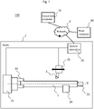
- Fig. 1 is an overall configuration diagram of a processing system according to Embodiment 1.
- a processing system 100 includes a conversion computer 10 as an example of an NC program generation system, a lathe 2, and a field computer 30.
- the conversion computer 10, the lathe 2, and the field computer 30 are coupled via a network 5.
- the network 5 may be a wired network or a wireless network.
- the lathe 2 and the field computer 30 may be disposed at the same location.
- the conversion computer 10 executes the process of generating an NC program for turning with higher machining accuracy (after-correction NC program) from an NC program generated by CAM (Computer Aided Manufacturing) (before-correction NC program).
- the lathe 2 includes a main spindle 21, a fixing jig 22, a tailstock 23, a stopper 24, a tool rest 25 as an example of a tool fixing unit, and a control apparatus 26.
- the main spindle 21 supports the fixing jig 22 so as to be rotatable.
- the fixing jig 22 is a jig for fixing a workpiece 1.
- the fixing jig 22 is a chuck.
- the fixing jig 22 may be fixing jig using bolt fastening, magnets, or the like; in short, it should be capable of fixing the workpiece 1 to the main spindle 21. With this configuration, the workpiece 1 is rotatably fixed to the main spindle 21 of the lathe 2 via the fixing jig 22.
- the tailstock 23 is disposed on a rotation axis O of the main spindle 21 at a position opposed to the main spindle 21.
- the tailstock 23 contacts an end surface of the workpiece 1 fixed to the main spindle 21 via the fixing jig 22 on the side opposite to an end surface thereof on the main spindle 21 side, and fixes the workpiece 1 so as to be rotatable.
- the stopper 24 supports the side surface of the workpiece 1 to prevent runout of the workpiece 1 during the turning process. According to the stopper 24, a workpiece with low rigidity can be machined appropriately, and the machining accuracy of the turning process can be increased.
- the tool rest 25 fixes the tool 3.
- the tool rest 25 is, for example, a turret, capable of fixing multiple tools, and by rotating the tool rest 25, the tool to be used for machining can be selected.
- the tool rest 25 does not have to be a turret, and may be capable of exchanging a tool stored in a tool magazine with a tool fixed to the tool rest 25 by an ATC (Automatic ToolChanger) apparatus (not illustrated), or may be capable of installing tools manually.
- the tool rest 25 may be equipped with a rotating spindle and may be capable of mounting a rotating tool such as a drill.
- the tool rest 25 is movable, for example, in the direction of the rotation axis O (which may not strictly coincide with this direction due to errors) or in the radial direction of the rotation axis O (which may not strictly coincide with this direction due to errors) by a drive mechanism (not illustrated), based on the control of the control apparatus 26.
- the tool 3 may also include an integrated bite with a cutting edge, an insert with a cutting edge and a bite to which the insert is mounted, and a holder to fix these bites to the tool rest 25.
- the control apparatus 26 controls the turning process by reading the NC program stored in an internal recording apparatus not illustrated in the figure, and controlling the operation of the workpiece and the tool based on the machining parameters (machining speed and feed rate) and the machining path (movement path) described in the NC program.
- the NC program may be data in which the lathe operation is described in a format such as G-code, or it may be data in a format which the lathe operation cannot be directly controlled such as CL (Cutter Location) data and in which the machining parameters and lathe operation such as the machining path and rotation speed are described.
- the control apparatus 26 may have a machining path generation function that generates a machining path (movement path) from the machining geometry and machining conditions.
- the opposite end of the workpiece 1 to the main spindle 21 can be turned without fixing it, so that the turning process is performed in the so-called cantilevered state.
- the opposite end of the workpiece 1 may be rotatably fixed to the other spindle via a fixing jig connected to that spindle, without a tailstock 23.
- the lathe 2 may also not be equipped with a stopper 24.
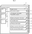
- Fig. 2 is a configuration diagram of the conversion computer according to Embodiment 1.
- the conversion computer 10 is, for example, a personal computer or a general-purpose computer.
- the conversion computer 10 includes a CPU 11 as an example of a processor, a network interface 12 (abbreviated as Net I/F in Fig. 2 ), a user interface 13 (User I/F in Fig. 2 ), storage resource 14 as an example of a storage unit, and an internal network for coupling the components.
- the CPU 11 can execute programs stored in the storage resource 14.
- the storage resource 14 stores therein programs to be executed by the CPU 11, various kinds of information used by the programs, and NC programs used by the lathe 2.
- the storage resource 14 may be, for example, a semiconductor memory, a flash memory, a hard disk drive (HDD), or a solid state drive (SSD).
- the storage resource 14 may be a volatile memory or a non-volatile memory.
- the network interface 12 is an interface for communicating with external apparatuses (for example, control apparatus 26 in lathe 2 and field computer 30) via the network 5.
- external apparatuses for example, control apparatus 26 in lathe 2 and field computer 30
- the user interface 13 is, for example, a touch panel, a display, a keyboard, a mouse, or the like.
- the user interface 13 may be another device as along as the user interface 13 can receive operations from an operator (user) and display information.
- the user interface 13 may be configured by these plurality of devices.
- the storage resource 14 stores a conversion program 1411, a configuration information acquisition program 1412, lathe configuration information 1413, tool information 1414, work information 1415, a before-correction NC program 1416, and an after-correction NC program 1417.
- the storage resource 14 may store information other than this. The details of each data and program are described starting from the next paragraph. Each information, or some items of each information, may be omitted.
- the lathe configuration information 1413 is configured, for example, as a table that stores information about the lathe 2.
- the lathe configuration information 1413 includes the following information. (a1) Identifier of the lathe 2 (lathe ID). The identifier of the control apparatus 26 or the network address may be substituted for the lathe ID.
- the information of (a1), (a2), (a4), (a5), (a8), and (a9) is obtained, for example, from the control apparatus 26 of the lathe 2 (or the field computer 30), while (a3), (a6), (a7), and (a10) are obtained from the input information by the user.
- the method of obtaining the information is not limited to this, and at least a part of (a1), (a2), (a4), (a5), (a8), and (a9) may be obtained from input information by the user via the user interface 13.
- the information that can be obtained from the control apparatus 26 (or the field computer 30) among (a3), (a6), (a7), and (a10) may be obtained from the control apparatus 26 (or the field computer 30).
- the information that is supposed to be acquired from the control apparatus 26 (or the field computer 30) may also be acquired from an alternative device (e.g., another computer or the sensor itself).
- the tool information 1414 is information about each tool 3.
- the tool information 1414 includes the following information.
- the information (b1) to (b3) is obtained from the input information via the user interface 13 by the user, for example, but information that can be obtained from the control apparatus 26 (or the field computer 30) may be obtained from the control apparatus 26 (or the field computer 30).
- the work information 1415 includes, for example, shape data of the workpiece 1 before machining, material, mechanical material property rigidity (Young's modulus, Poisson's ratio, transverse modulus of elasticity, etc.), and machining target shape data of the workpiece 1, and the like.
- the machining target shape data is the data that indicates the target shape when machining by the NC program. If the workpiece 1 can be machined to the target shape concerned, it means that the error is zero.
- the work information 1415 may be obtained from the control apparatus 26 (or the field computer 30), or from input information via the user interface 13 by the user.
- the before-correction NC program 1416 is an NC program created by CAM to be used on a lathe.
- the before-correction NC program 1416 is generated and transmitted by a computer equipped with CAM, which is not illustrated in the figure.
- the after-correction NC program 1417 is the NC program obtained by converting the before-correction NC program 1416 to fit the turning process for a specific workpiece on the lathe 2. If no conversion process has been performed on any of the before-correction NC programs 1416, the after-correction NC program 1417 does not exist.
- the conversion program 1411 is executed by the CPU 11 to perform the following processes.
- the conversion program 1411 executes the process of generating the after-correction NC program 1417 from the before-correction NC program 1416. The details of the process will be described later.
- the configuration information acquisition program 1412 is executed by the CPU 11 to perform the following processes.
- the configuration information acquisition program 1412 acquires various information about the lathe 2 from the control apparatus 26 of the lathe 2.
- the information to be acquired includes the information on (a1), (a2), (a4), (a5), (a8), and (a9) described above.
- the configuration information acquisition program 1412 acquires various information from the user via the user interface 13 (information about the lathe 2 to be acquired from the user ((a3), (a6), (a7), and (a10)), and information about the tool information 1414 ((b1) to (b3)).
- Fig. 3 is a functional configuration diagram of the conversion computer according to Embodiment 1.
- the conversion computer 10 includes an input unit 41, a deflection calculation unit 42, and a machining path determination unit 43.
- the input unit 41 is configured by the CPU 11 executing the configuration information acquisition program 1412
- the deflection calculation unit 42 and the machining path determination unit 43 are configured by the CPU 11 executing the conversion program 1411.
- the input unit 41 inputs the shape of the workpiece, the mechanical material properties of the workpiece, and the rigidity of the part of the lathe 2 that fixes the workpiece (the main spindle 21 and the fixing jig 22: an example of fixing unit, and these are referred to as workpiece fixing unit) .
- the input unit 41 inputs the before-correction NC program 1416.
- the shape of the workpiece may be the shape of the workpiece before machining (material shape) or the target shape after machining of the workpiece.
- the mechanical material properties of the workpiece include at least the Young's modulus of the material of the workpiece.
- the mechanical material properties may also include Poisson's ratio or transverse modulus of elasticity.
- the stiffness of the workpiece fixing unit includes the translational spring coefficient and rotational spring coefficient at the workpiece fixing unit.
- the translational spring coefficient is the reciprocal of the displacement for a unit load
- the rotational spring coefficient is the reciprocal of the deflection angle for a unit moment.
- the translational spring coefficient and rotational spring coefficient can be identified in advance by analysis or measurement, and the identified coefficients can be used.
- the deflection calculation unit 42 calculates the displacements occurring to the workpiece at multiple machining positions.
- the displacements generated against the workpiece include the deflection of the workpiece and the displacement caused by the deflection of the workpiece fixing unit to which the workpiece is mounted. Since the rigidity of the workpiece fixing unit is higher than the rigidity of the workpiece, the latter displacement may not be included in the displacements occurring against the workpiece in some cases. Since the workpiece to be turned is generally rotationally symmetric, the workpiece can be modeled as a stepped beam, and the deflection of the workpiece can be calculated by using the finite elements of the beam.
- the deflection calculation unit 42 analyzes the machining path before correction, that is, the machining path when the deflection of the workpiece, etc., is not taken into account, and identifies a plurality of machining positions.
- the machining path before correction can be identified from the commands (blocks) of the before-correction NC program 1416. If the machining path is generated based on the target shape of the workpiece in the control apparatus 26, the generated machining path can be used.
- the displacement at a certain machining position can be calculated by dividing the stepped beam model of the workpiece at the target machining position, setting a node, giving the cutting force in the turning process as a shear load, and solving for the rigidity of the workpiece fixing unit as a boundary condition.
- the shape of the workpiece used as a stepped beam model is preferably the shape of the workpiece (intermediate shape) when it reaches the target machining position by successively removing the parts that interfere with the tool based on the material shape, but it may also be the material shape or the target shape after machining.
- the cutting force is preferably calculated by analyzing the volume, cross-sectional area, and depth of cut of the removed area at the target machining position, but it may be obtained from the machining conditions such as the set depth of cut and feed, or the cutting force measured during actual machining may be used.
- the machining path determination unit 43 uses the calculated displacement to determine an appropriate machining path. If the workpiece is displaced during machining due to deformation caused by deflection, etc., the machining amount will change and the diameter of the workpiece after machining will deviate from the target value. Therefore, when the workpiece is displaced away from the tool 3, the diameter of the workpiece after machining becomes larger than the target value. Therefore, the machining path determination unit 43 determines the machining path after correction by moving the machining path closer to the workpiece side to increase the depth of cut by the tool 3 so that the diameter becomes the target diameter with the workpiece displaced. When the workpiece is displaced so that it moves closer to the tool 3, the diameter of the workpiece after machining becomes smaller than the target value.
- the machining path determination unit 43 determines the machining path after correction by moving the machining path away from the workpiece to reduce the depth of cut by the tool 3 so that the diameter becomes the target diameter with the workpiece displaced.
- the positional coordinates of the before-correction NC program 1416 may be edited to the new positional coordinates after correction, or the positional coordinates of the before-correction NC program 1416 may be used as they are, and the value of the tool offset may be changed based on the difference between the positional coordinates before and after correction.
- the position coordinates of the before-correction NC program 1416 are used as they are and the tool offset is changed, the position coordinates configured in the before-correction NC program 1416 are also saved in the after-correction NC program1417, making it easier for the user to check the NC program and the readability of the after-correction NC program 1417 can be maintained.
- the machining path may be specified as a curve obtained by NURBS (Non-uniform rational B-spline) interpolation.
- the machining path may be an approximate broken line path obtained by dividing the machining path described in blocks of the NC program into a plurality of parts and performing a linear interpolation, or an approximate multi-circular arc path by performing a circular interpolation.
- machining path correction is performed by changing the tool offset, it is desirable to use an approximate broken line path by linear interpolation.
- the machining path determination unit 43 may directly generate the machining path after correction that takes the displacement of the workpiece into account, without generating the machining path before correction.
- the field computer 30 is, for example, a personal computer or a general-purpose computer.
- the field computer 30 includes a CPU as an example of a processor, a network interface, a user interface, storage resource as an example of a storage unit, and an internal network coupling these components.
- the storage resource of the field computer 30 stores a client program.
- the storage resource may also store the before-correction NC program.
- the client program is executed by the CPU to perform the following processes.
- the client program instructs the conversion computer 10 to convert the NC program, receives the after-correction NC program from the conversion computer 10, and stores the after-correction NC program in the storage resource of the field computer 30 or the recording apparatus of the control apparatus 26.
- the client program may read the before-correction NC program instructed by the user from the storage resource and send it to the conversion computer 10.
- the client program may accept information input to the conversion computer 10 from the user via the user interface 13, or information input by the user from the control apparatus 26, etc., from the user of the field computer 30 instead of these, and send them to the conversion computer 10.
- the configuration information acquisition program 1412 (strictly speaking, the CPU 11 executing the configuration information acquisition program 1412) acquires various information on the lathe 2 (e.g., (A1), (A2), (A4), (A5), (A8), and (A9)) that can be obtained from the control apparatus 26 of the lathe 2 coupled via the network 5. This process does not need to be performed every time the process 2 and subsequent processes described below are performed.
- the configuration information acquisition program 1412 receives the specification of the before-correction NC program 1416, which is to be converted, from the operator via the user interface 13.
- the configuration information acquisition program 1412 receives various information on the lathe 2 ((A3), (A6), (A7), and (A10)), information on the tools used on the lathe 2 ((B1) to (B3)), shape data before machining, material, and mechanical material property rigidity (Young's modulus, Poisson's ratio, transverse modulus of elasticity, etc.) of the workpiece 1 used on the lathe 2, and the machining target shape data of the workpiece 1 (direct input or selection input).
- the configuration information acquisition program 1412 sends a conversion start instruction to the conversion program 1411.
- the conversion start instruction includes various information input (direct input or selection input) via the user interface 13.
- the conversion program 1411 When the conversion program 1411 receives the conversion start instruction, it reads the specified before-correction NC program 1416, executes the conversion process to convert the before-correction NC program 1416 into the after-correction NC program 1417, and stores the after-correction NC program 1417 generated by the conversion in the storage resource 14.
- the conversion program 1411 sends the after-correction NC program 1417 stored in the storage resource 14 to the control apparatus 26 of the lathe 2.
- control apparatus 26 of the lathe 2 executes the turning process on the workpiece 1 by executing the after-correction NC program 1417.
- Fig. 4 is a flowchart for conversion process according to one embodiment.
- the conversion program 1411 reads all blocks of the before-correction NC program 1416 to be processed to the work area of the memory among the storage resource 14 (S11) .
- a block indicates the part of the description that contains instructions (addresses) that can be instructed to the lathe 2 at one time in the machining process executed by the before-correction NC program 1416.
- a block includes one or more instructions (addresses) that can be instructed at the same time.
- the address may include, for example, a code indicating the type of instruction and a parameter regarding the content of the instruction. If the capacity of the before-correction NC program 1416 is too large to call up all blocks in the work area of the memory, the blocks to be read can be switched according to the progress of process.
- all blocks of the before-correction NC program 1416 to be processed may not be read out at once to the work area of the storage resource 14, but may be read out one block at a time, for example.
- the conversion program 1411 performs the loop 1 process (steps S12 to S19) for each block read in step S11.
- the block to be processed in Loop 1 is called a target block.
- the conversion program 1411 determines whether the target block is a movement instruction in the direction of the rotation axis O of the main spindle 21 (Step S12) . As a result, if the target block is not the movement instruction in the direction of the rotation axis O (Step S12: N), the conversion program 1411 proceeds the process to the end of Loop 1 (after Step S19).
- Step S12 determines whether or not the machining path of the movement instruction of the target block needs to be divided (Step S13). For example, if the length of the machining path in the direction of the rotation axis O is more than a predetermined value, it may be determined that the machining path needs to be divided.
- Step S13 if it is determined that the machining path of the movement instruction of the target block needs to be divided (Step S13: Y), the conversion program 1411 divides the machining path into a plurality of unit paths (Step S14).
- the number of divisions is arbitrary, but basically, the greater the number of divisions, the more detailed and appropriate the machining path can be identified.
- Step S13 the conversion program 1411 determines the machining path of the target block as a unit path (Step S15).
- step S14 After determining the unit path in step S14 or step S15, the conversion program 1411 performs the loop 2 process (steps S16 and S17) for each unit path.
- the conversion program 1411 calculates the radial displacement of the rotation axis of the workpiece at the end point in the rotation axis direction of the unit path (step S16) .
- the conversion program 1411 corrects the coordinates in the radial direction of the end point of the unit path and determines the corrected unit path. Specifically, the conversion program 1411 adds the displacement calculated in step S16 to the coordinates in the radial direction at the end point of the unit path (step S17) .
- the conversion program 1211 exits the process of loop 2 and determines a corrected machining path for the machining path of the target block based on the corrected unit path (step S18) .
- the corrected machining path may be determined by connecting the end points of all the corrected unit paths with straight lines, or by obtaining an approximate line (straight line or curve) based on each end point.
- the corrected machining path is an approximate line, the corrected machining path may be divided in the direction of the rotation axis, and the number of divisions may be determined so that the approximation error at each divided point is less than a predetermined value.
- the conversion program 1411 generates a correction block (or group of blocks), which is the block (or group of blocks) that corresponds the corrected machining path determined in step S18, and replaces the target block in the work area with the generated correction block (or group of correction blocks) (step S19) .
- the conversion program 1411 executes the loop 1 process for the target block, it performs the loop 1 process with the next block as the target block, and exits the loop 1 process when it has performed the loop 1 process for all blocks.
- the conversion program 1411 stores the NC program in the work area in the storage resource 14 as the after-correction NC program 1417 (Step S20), and ends the process.
- the machining path is corrected based on the radial displacement of the rotation axis due to deflection of the workpiece, etc., and the block corresponding to the corrected machining path is generated, so that an after-correction NC program can be generated that can appropriately suppress the effects of displacement due to deflection of the workpiece, etc., in the turning process.
- an after-correction NC program can be generated that can appropriately suppress the effects of displacement due to deflection of the workpiece, etc., in the turning process.
- Fig. 5 the state of the turning process for the comparative example.
- Fig. 5(A) illustrates the state before cutting
- Fig. 5(B) illustrates the state of cutting a distal end side of the workpiece
- Fig. 5 (C) illustrates the state of cutting the vicinity of the fixing jig of the workpiece
- Fig. 5(D) illustrates the state after cutting is completed.
- the machining path Pb is a path parallel to the rotation axis O toward the main spindle 21.
- the workpiece 1 is displaced downward as illustrated in Fig. 5(C), even in the vicinity of the fixing jig 22.
- the amount of displacement of the workpiece 1 is smaller than that during cutting on the distal end side.
- the machining accuracy of the workpiece 1 obtained by machining is poor.
- Fig. 6 illustrates the state of the turning process for Embodiment 1.
- Fig. 6(A) illustrates the state before cutting
- Fig. 6(B) illustrates the state of cutting the distal end side of the workpiece
- Fig. 6 (C) illustrates the state of cutting the vicinity of the fixing jig of the workpiece
- Fig. 6(D) illustrates the state after cutting is completed.
- the machining path Pa is corrected so that the closer to the distal end part of the workpiece 1, where displacement is large, the machining path of the tool 3 is lower in the drawing with respect to the machining path Pb.
- the workpiece 1 is displaced downward as illustrated in Fig. 6(C), even in the vicinity of the fixing jig 22.
- the amount of displacement of the workpiece 1 is smaller than when cutting the distal end side, but the position of the machining path Pa is higher in the drawing than that of the distal end side, resulting in a depth of cut that is almost the same as that of the distal end side in Fig. 6(B).
- the amount of correction of the machining path is larger the closer it is to the distal end part of the workpiece 1, which has a larger displacement, and the amount of correction of the machining path is smaller the closer it is to the fixing jig 22, which has a smaller displacement, so that the depth of cut by the tool 3 is almost the same in the entire range in the direction of the rotation axis O.
- the shape of the workpiece 1 after the cutting is completed can be made almost the same diameter as illustrated in Fig. 6(D).
- the machining accuracy of the workpiece 1 obtained by machining can be improved. If the displacement occurring in the workpiece includes the displacement caused by the workpiece fixing unit, the machining accuracy can be further improved because the deterioration of the machining accuracy due to the displacement of the workpiece caused by the workpiece fixing unit can be suppressed.
- Fig. 7 illustrates an example of the relationship between the rotation axis of the lathe and the movement axis of the tool rest.
- the inclination (inter-axis inclination) between the rotation axis O of the main spindle 21 and the movement axis (Z-axis) in the direction of the rotation axis of the tool rest 25 is measured in advance, and the input unit 41 accepts the inter-axis inclination (an example of angle information), and the deflection calculation unit 42 adds the displacement of the workpiece at the machining position for which the displacement of the workpiece is to be calculated and the displacement based on the interaxial inclination at the process position, and based on the added displacement, determines the corrected machining path in the same manner as described above.
- Fig. 8 illustrates the experimental results of diameter error due to turning between Embodiment 1 and the comparative example.
- a round bar of S45C (Young's modulus 206 GPa, Poisson's ratio 0.3, diameter 50 mm, length 800 mm) was used as workpiece 1.
- the workpiece 1 was fixed by the fixing jig 22 by 50 mm, and an end surface of the workpiece 1 on the side opposite to the fixing jig 22 was fixed by the tailstock 23.
- Turning was performed using the before-correction NC program 1416 and the after-correction NC program 1417, respectively, with a number of revolutions of 650 min -1 , a feed of 0.1 mm/rev, and a depth of cut of 0.1 mm.
- the inclination of the workpiece 1 was assumed to be 0.016 mm at the end face of the tailstock.
- the maximum diameter error was 0.030 mm.
- the maximum diameter error was 0.010 mm. This means that the maximum diameter error of the workpiece 1 can be reduced by performing the turning process with the after-correction NC program 1417.
- the before-correction NC program is converted to the after-correction NC program, which is corrected to the machining path determined based on the displacement including the deflection of the workpiece during machining, so that the machining accuracy in the turning process on the lathe 2 can be improved.
- Embodiment 2 Next, a conversion computer according to Embodiment 2 is described.
- Embodiment 2 for the sake of convenience, the same symbols as in the conversion computer according to Embodiment 1 are used, and the differences are mainly described.
- the conversion computer according to Embodiment 2 takes into account the displacements including deflection of the tool 3 to improve the machining accuracy.
- the input unit 41 accepts the shape of the tool 3, the mechanical material properties of the tool 3, and the rigidity information of the tool rest 25.
- the deflection calculation unit 42 further calculates the displacement due to deflection of the tool 3 and the like. Similar to the method for calculating the deflection of a workpiece, the deflection of the tool 3 can be calculated as the displacement of the cutting edge as the tool deflection by giving the cutting force as a shear load loaded on the cutting edge portion and solving the stiffness matrix with the spring coefficient at the end face of the tool rest 25 as the boundary condition.
- the relative machining error seen from the tool 3 is the sum of the displacement of the workpiece 1 and the displacement of the tool 3.
- the deflection calculation unit 42 calculates the displacement by adding the displacement of the workpiece 1 and the displacement of the tool 3.
- the machining path determination unit 43 determines the corrected machining path by using the displacement calculated by adding the displacements of the workpiece 1 and the tool 3 calculated by the deflection calculation unit 42 and performing the same process as in Embodiment 1.
- the corrected machining path can take into account the displacement of the workpiece 1 and the displacement of the tool 3, the effect of these displacements on the cutting process can be reduced, and the machining accuracy of the workpiece can be improved.
- Embodiment 3 Next, a conversion computer according to Embodiment 3 is described.
- Embodiment 3 for the sake of convenience, the same symbols as in the conversion computer according to Embodiment 1 are used, and the differences are mainly described.
- the rigidity of the workpiece 1 is extremely low, if an attempt is made to offset machining errors caused by distortion of the workpiece 1 by only changing the machining path, the cutting depth by the tool 3 may become excessively large and the workpiece 1 may be plastically deformed or damaged.
- the feed rate of the tool 3 is corrected in addition to the correction of the machining path.
- the conversion program 1411 e.g., the machining path determination unit 43
- the conversion program 1411 corrects the feed rate of the tool 3 to reduce the feed rate of the tool 3 to become the target amount of compensation, when the amount of correction of the machining path is large according to the feed rate before correction described in the before-correction NC program 1416, and the amount of correction is configured to the target correction amount. In this way, damage to the workpiece 1 can be suppressed.
- the conversion program 1411 may correct to increase the feed rate before correction, and the correction amount of the machining path may be the correction amount corresponding to the feed rate after correction.
- the feed rate during machining at the vicinity of the fixing jig 22 can be faster than the feed rate during machining of the leading edge of the workpiece 1 because of the higher rigidity in the vicinity of the fixing jig 22.
- Fig. 9 illustrates values related to turning of a workpiece.
- the cutting force F applied to the workpiece 1 can be modeled by the following equation (1).
- F Kc ⁇ Vf / S + Ke ⁇ a
- a is the depth of cut illustrated in Fig. 9
- Vf is the feed rate illustrated in Fig. 9
- S is the rotational speed of the workpiece illustrated in Fig. 9
- Kc is the cutting force coefficient for the cutting cross-sectional area
- Ke is the cutting force coefficient for the depth of cut.
- the corrected feed rate Vft can be expressed by the following equation (2).
- Vft ⁇ t/ ⁇ ⁇ Vf + ⁇ t/ ⁇ ⁇ 1 ⁇ S ⁇ Ke / Kc
- the machining path determination unit 43 determines the target displacement ⁇ t, makes the correction to change the feed rate calculated according to formula (2), corrects the machining path according to the displacement ⁇ t, and outputs the corresponding after-correction NC program.
- the feed rate Vft to be corrected may be determined first, and then the displacement ⁇ t may be calculated according to the relationship in Equation (2).
- Embodiment 4 Next, a conversion computer according to Embodiment 4 is described.
- Embodiment 4 for the sake of convenience, the same symbols as in the conversion computer according to Embodiment 1 are used, and the differences are mainly described.
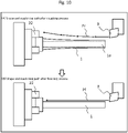
- Fig. 10 illustrates a roughing machining and a finishing process machining to Embodiment 4.
- roughing machining may first be performed to machine the workpiece 1 to a shape close to the target shape, followed by finishing machining to machine the workpiece to the final target shape.
- the feed rate of the tool 3 is changed during the finishing machining, the machined surface roughness of the workpiece will change, and the appearance of the workpiece will change at the part where the feed rate is changed, which may cause appearance problems .
- the machining path is approximated by a broken line or the like, the movement direction vector of the tool 3 changes at the changeover of the line segment of the machining path, and the appearance of the workpiece 1 may become problematic due to the appearance of swirls on the machined surface. For this reason, it may not be desirable to change the feed rate of the tool 3 or the machining path on the machined surface in the finishing machining.
- the conversion program 1411 for the NC program for roughing machining, ensures that the displacement of the workpiece 1 in the subsequent finishing machining is constant in the direction of the rotation axis. Specifically, the conversion program 1411 determines the machining path Pr (movement path for roughing machining) such that the depth of cut in roughing machining is increased so that the finishing allowance is decreased in the part where the rigidity of the workpiece 1 is low, and the depth of cut in roughing machining is decreased so that the finishing allowance is relatively increased in the part where the rigidity of the work is high, as illustrated in Fig. 10(A).
- Pr movement path for roughing machining
- the displacement ⁇ in the finishing machining can be expressed by equation (3) using the stiffness K in the finishing machining.
- ⁇ F / K
- the conversion program 1411 generates the machining path Pr illustrated in Fig. 10(B), which leaves a finishing allowance a such that a/K is constant at each machining position in the NC program for roughing machining.
- the machining path Pf of finishing machining can be configured to an offset from the machining path in the before-correction NC program 1416, so that no swirls remain on the machined surface.
- the feed rate and machining path are not changed during machining, and highly accurate machining can be achieved.
- the conversion program 1411 determines whether to perform roughing machining process or not, and executes either roughing machining process or normal process depending on the result.
- the before-correction NC program may include a comment indicating whether or not the roughing machining process is to be performed, and the determination may be made based on the comment.
- the tool number or the tool offset number it may be defined that the tool is a roughing machining tool or a finishing machining tool, and based on whether the tool in the before-correction NC program is a roughing machining tool or not, it may be determined whether to perform roughing machining process or not. Also, whether or not the before-correction NC program is for roughing machining may be managed by NC program number or file name, and whether or not to perform roughing machining process may be determined based on the number or file name of the before-correction NC program.
- this embodiment is not limited to the combination of roughing machining and finishing machining, but can also be applied to pre-machining (e.g., mid-finishing machining or mid-machining, which also includes roughing machining), which is the machining before finishing machining.
- pre-machining e.g., mid-finishing machining or mid-machining, which also includes roughing machining
- pre-machining e.g., mid-finishing machining or mid-machining, which also includes roughing machining
- the radial displacement of the workpiece is made constant over the entire machining range of the workpiece in the direction of the rotational axis, but the invention is not limited to this.
- the radial displacement of the workpiece may be made constant in a part of the machining range of the workpiece in the direction of the rotation axis. In this way, the machining accuracy in the part of the machining range can be improved.
- the program in the above embodiments may be installed from a program source.
- the program source may be a program distribution server or a non-volatile storage media (e.g., a portable storage media).
- NC program generation system being configured with the conversion computer 10
- the NC program generation system may be configured with the control apparatus 26 of the lathe 2.
- the functions of the conversion computer 10 may be provided to the control apparatus 26.
- the NC program generation system may be configured with multiple computers, and in this case, the functions of the conversion computer 10 can be executed by the processors of the multiple computers.
Landscapes
- Engineering & Computer Science (AREA)
- Physics & Mathematics (AREA)
- Human Computer Interaction (AREA)
- Manufacturing & Machinery (AREA)
- General Physics & Mathematics (AREA)
- Automation & Control Theory (AREA)
- Geometry (AREA)
- Mechanical Engineering (AREA)
- Numerical Control (AREA)
- Turning (AREA)
Applications Claiming Priority (2)
| Application Number | Priority Date | Filing Date | Title |
|---|---|---|---|
| JP2019136459A JP7112375B2 (ja) | 2019-07-24 | 2019-07-24 | Ncプログラム生成システム及びncプログラム生成方法 |
| PCT/JP2020/020805 WO2021014749A1 (fr) | 2019-07-24 | 2020-05-26 | Système de génération de programme à commande numérique et procédé de génération de programme à commande numérique |
Publications (2)
| Publication Number | Publication Date |
|---|---|
| EP4006667A1 true EP4006667A1 (fr) | 2022-06-01 |
| EP4006667A4 EP4006667A4 (fr) | 2023-08-02 |
Family
ID=74193300
Family Applications (1)
| Application Number | Title | Priority Date | Filing Date |
|---|---|---|---|
| EP20843463.9A Pending EP4006667A4 (fr) | 2019-07-24 | 2020-05-26 | Système de génération de programme à commande numérique et procédé de génération de programme à commande numérique |
Country Status (5)
| Country | Link |
|---|---|
| US (1) | US12030148B2 (fr) |
| EP (1) | EP4006667A4 (fr) |
| JP (1) | JP7112375B2 (fr) |
| CN (1) | CN113874799B (fr) |
| WO (1) | WO2021014749A1 (fr) |
Cited By (1)
| Publication number | Priority date | Publication date | Assignee | Title |
|---|---|---|---|---|
| EP4296809A1 (fr) * | 2022-06-22 | 2023-12-27 | The Boeing Company | Système et procédé de fabrication de composite |
Families Citing this family (3)
| Publication number | Priority date | Publication date | Assignee | Title |
|---|---|---|---|---|
| JP7436181B2 (ja) * | 2019-11-08 | 2024-02-21 | ファナック株式会社 | たわみ量算出装置及びプログラム |
| KR102852722B1 (ko) * | 2023-08-16 | 2025-09-01 | 한국생산기술연구원 | 머신비전을 이용한 공구 동특성 예측 방법 |
| JP7786663B1 (ja) * | 2025-07-01 | 2025-12-16 | 住友電工ハードメタル株式会社 | 工具情報提示システム、工具情報提示装置、及び工具情報提示方法 |
Family Cites Families (29)
| Publication number | Priority date | Publication date | Assignee | Title |
|---|---|---|---|---|
| JPS61781A (ja) | 1984-06-13 | 1986-01-06 | Mitsubishi Electric Corp | タイムスイツチの開閉装置 |
| US4707793A (en) * | 1985-09-30 | 1987-11-17 | The Boeing Company | Method of determining feed rate and cutting speed for cutting metal and of predicting cutting effects |
| JPS645753A (en) | 1987-06-26 | 1989-01-10 | Toshiba Machine Co Ltd | Compensation of misalignment of work in machine tool under numerical control |
| JPH0452908A (ja) | 1990-06-20 | 1992-02-20 | Fanuc Ltd | 工具変形量補正方式 |
| JPH06282321A (ja) * | 1992-01-16 | 1994-10-07 | Shin Nippon Koki Kk | 工作機械の数値制御プログラム変換作成方法及び装置並びに数値制御工作機械 |
| JPH09150348A (ja) * | 1995-11-28 | 1997-06-10 | Fanuc Ltd | Nc工作機械における切削誤差補正方法 |
| JPH11216642A (ja) * | 1998-02-04 | 1999-08-10 | Mori Seiki Co Ltd | Nc旋盤における旋削加工法 |
| US7392109B2 (en) * | 2000-07-31 | 2008-06-24 | Kabushiki Kaisha Toyota Chuokenkyusho | System for integrally generating NC data |
| US6804575B2 (en) * | 2000-10-26 | 2004-10-12 | Citizen Watch Co., Ltd. | Method and device for automatically preparing processing program |
| JP2002230317A (ja) | 2001-01-30 | 2002-08-16 | Toyota Central Res & Dev Lab Inc | 加工情報提供装置、加工情報提供システム、及び記録媒体 |
| JP3840389B2 (ja) * | 2001-09-26 | 2006-11-01 | 株式会社ジェイテクト | 加工方法および加工装置 |
| JP2004265024A (ja) * | 2003-02-28 | 2004-09-24 | Kinichi Inagaki | 加工プログラムを理解して固有のncデータ変換生成をする知的管理するcnc装置 |
| JP2005074569A (ja) * | 2003-09-01 | 2005-03-24 | Mitsubishi Heavy Ind Ltd | プログラム、コンピュータ装置、多軸加工機、ncプログラムの生成方法、ワークの加工方法 |
| JP4491681B2 (ja) | 2004-06-29 | 2010-06-30 | 株式会社ニイガタマシンテクノ | 工作機械における回転テーブルの位置決め制御方法および位置決め制御装置 |
| JP4568139B2 (ja) * | 2005-02-22 | 2010-10-27 | 野村Vtc株式会社 | 自動旋盤及びこれによる裏面加工方法 |
| JP4885113B2 (ja) | 2007-11-22 | 2012-02-29 | 株式会社神戸製鋼所 | 切削加工方法と切削加工装置 |
| JP5372598B2 (ja) * | 2009-05-15 | 2013-12-18 | 株式会社森精機製作所 | 加工方法及び加工システム |
| JP5337330B2 (ja) | 2009-08-27 | 2013-11-06 | 富士機械製造株式会社 | 切削機械及びその加工位置補正方法 |
| JP5792649B2 (ja) * | 2011-03-17 | 2015-10-14 | 株式会社日立製作所 | Ncプログラム生成方法 |
| JP5385330B2 (ja) * | 2011-03-29 | 2014-01-08 | 三菱電機株式会社 | 高精度加工装置 |
| JP6124721B2 (ja) * | 2013-07-22 | 2017-05-10 | 三菱電機株式会社 | 数値制御装置および数値制御方法 |
| CN106662860B (zh) * | 2014-08-12 | 2019-01-08 | 三菱电机株式会社 | 数控装置 |
| JP6235167B2 (ja) * | 2015-05-29 | 2017-11-22 | 株式会社日立製作所 | 加工装置 |
| US10054929B1 (en) * | 2015-07-02 | 2018-08-21 | Accenture Global Solutions Limited | Intelligent machine tools |
| WO2018011990A1 (fr) * | 2016-07-15 | 2018-01-18 | 株式会社牧野フライス製作所 | Dispositif de génération de programme d'usinage et procédé d'usinage |
| JP6470251B2 (ja) * | 2016-12-26 | 2019-02-13 | ファナック株式会社 | 数値制御装置及び機械学習装置 |
| JP6646027B2 (ja) * | 2017-10-30 | 2020-02-14 | ファナック株式会社 | ポストプロセッサ装置、加工プログラム生成方法、cnc加工システム及び加工プログラム生成用プログラム |
| CN109746465A (zh) | 2018-09-26 | 2019-05-14 | 江苏师范大学 | 一种车削振动-车削变形-车削温度实时监测与分析系统 |
| CN109175417B (zh) * | 2018-09-26 | 2020-07-03 | 江苏师范大学 | 一种车削工件准静态变形的理论计算及动变形的实测方法 |
-
2019
- 2019-07-24 JP JP2019136459A patent/JP7112375B2/ja active Active
-
2020
- 2020-05-26 US US17/627,939 patent/US12030148B2/en active Active
- 2020-05-26 WO PCT/JP2020/020805 patent/WO2021014749A1/fr not_active Ceased
- 2020-05-26 CN CN202080038797.8A patent/CN113874799B/zh active Active
- 2020-05-26 EP EP20843463.9A patent/EP4006667A4/fr active Pending
Cited By (1)
| Publication number | Priority date | Publication date | Assignee | Title |
|---|---|---|---|---|
| EP4296809A1 (fr) * | 2022-06-22 | 2023-12-27 | The Boeing Company | Système et procédé de fabrication de composite |
Also Published As
| Publication number | Publication date |
|---|---|
| CN113874799A (zh) | 2021-12-31 |
| WO2021014749A1 (fr) | 2021-01-28 |
| EP4006667A4 (fr) | 2023-08-02 |
| US20220258296A1 (en) | 2022-08-18 |
| US12030148B2 (en) | 2024-07-09 |
| CN113874799B (zh) | 2024-04-02 |
| JP2021022014A (ja) | 2021-02-18 |
| JP7112375B2 (ja) | 2022-08-03 |
Similar Documents
| Publication | Publication Date | Title |
|---|---|---|
| US12030148B2 (en) | NC program generation system and NC program generation method | |
| JP6942577B2 (ja) | 工作機械の数値制御装置及び数値制御方法 | |
| US10768607B2 (en) | Machining device and correction value determination method | |
| EP3872588B1 (fr) | Procédé de traitement de conversion de programme nc et ordinateur pour conversion | |
| JP5413913B2 (ja) | 旋削による非円形加工方法 | |
| JP6854658B2 (ja) | 加工装置及び加工方法 | |
| JP7562175B1 (ja) | 情報処理装置、情報処理方法およびプログラム | |
| EP0487738B1 (fr) | Systeme pour corriger une grandeur de deformation d'un outil | |
| JP6695306B2 (ja) | 工作機械、加工方法、および加工プログラム | |
| JP5929065B2 (ja) | Ncデータ補正装置 | |
| JP5778649B2 (ja) | 並進回転誤差補正量作成装置 | |
| JP2019069490A (ja) | 工作機械、加工方法、および加工プログラム | |
| JP2009146057A (ja) | 位置誤差補正方法、及び位置誤差補正装置 | |
| JP2003005813A (ja) | オービットボーリングの制御方法 | |
| JP2005202844A (ja) | 数値制御装置 | |
| JP2023046731A (ja) | 加工支援装置および加工用データ補正方法 | |
| JP2007118100A (ja) | 回転軸対称曲面の加工方法、回転軸対称曲面加工装置 | |
| JP2024136846A (ja) | 切削加工に用いる振動特性データベース、切削加工の安定性評価装置、切削加工プログラム生成装置、切削加工の安定性評価方法、および切削加工プログラム生成方法 | |
| JP2007175804A (ja) | 工作機械の制御装置 | |
| US20200174440A1 (en) | Numerical control device, program recording medium and control method | |
| CN118143739A (zh) | 机床布莱恩误差测量方法、装置及机床直线度测量的误差补偿方法 | |
| JP2024063495A (ja) | 加工治具制御プログラム生成システム、加工治具制御プログラム生成装置及び加工治具制御プログラム生成方法 | |
| EP3447592B1 (fr) | Contrôle de la vitesse d'avance d'une machine de fraisage | |
| CN119292185B (zh) | 基于多模型的加工路径插补数控系统及机床 | |
| TWI233383B (en) | Numerical control machine |
Legal Events
| Date | Code | Title | Description |
|---|---|---|---|
| STAA | Information on the status of an ep patent application or granted ep patent |
Free format text: STATUS: THE INTERNATIONAL PUBLICATION HAS BEEN MADE |
|
| PUAI | Public reference made under article 153(3) epc to a published international application that has entered the european phase |
Free format text: ORIGINAL CODE: 0009012 |
|
| STAA | Information on the status of an ep patent application or granted ep patent |
Free format text: STATUS: REQUEST FOR EXAMINATION WAS MADE |
|
| 17P | Request for examination filed |
Effective date: 20220111 |
|
| AK | Designated contracting states |
Kind code of ref document: A1 Designated state(s): AL AT BE BG CH CY CZ DE DK EE ES FI FR GB GR HR HU IE IS IT LI LT LU LV MC MK MT NL NO PL PT RO RS SE SI SK SM TR |
|
| DAV | Request for validation of the european patent (deleted) | ||
| DAX | Request for extension of the european patent (deleted) | ||
| A4 | Supplementary search report drawn up and despatched |
Effective date: 20230703 |
|
| RIC1 | Information provided on ipc code assigned before grant |
Ipc: B23Q 15/00 20060101ALI20230627BHEP Ipc: G05B 19/404 20060101ALI20230627BHEP Ipc: G05B 19/4093 20060101AFI20230627BHEP |
|
| STAA | Information on the status of an ep patent application or granted ep patent |
Free format text: STATUS: EXAMINATION IS IN PROGRESS |
|
| 17Q | First examination report despatched |
Effective date: 20240910 |