EP4007675B1 - Système de préhension robotique - Google Patents
Système de préhension robotique Download PDFInfo
- Publication number
- EP4007675B1 EP4007675B1 EP20859843.3A EP20859843A EP4007675B1 EP 4007675 B1 EP4007675 B1 EP 4007675B1 EP 20859843 A EP20859843 A EP 20859843A EP 4007675 B1 EP4007675 B1 EP 4007675B1
- Authority
- EP
- European Patent Office
- Prior art keywords
- eoat
- jaws
- interface
- mechanical interface
- gripping device
- Prior art date
- Legal status (The legal status is an assumption and is not a legal conclusion. Google has not performed a legal analysis and makes no representation as to the accuracy of the status listed.)
- Active
Links
Images


Classifications
-
- B—PERFORMING OPERATIONS; TRANSPORTING
- B25—HAND TOOLS; PORTABLE POWER-DRIVEN TOOLS; MANIPULATORS
- B25J—MANIPULATORS; CHAMBERS PROVIDED WITH MANIPULATION DEVICES
- B25J15/00—Gripping heads and other end effectors
- B25J15/04—Gripping heads and other end effectors with provision for the remote detachment or exchange of the head or parts thereof
- B25J15/0475—Exchangeable fingers
-
- B—PERFORMING OPERATIONS; TRANSPORTING
- B25—HAND TOOLS; PORTABLE POWER-DRIVEN TOOLS; MANIPULATORS
- B25J—MANIPULATORS; CHAMBERS PROVIDED WITH MANIPULATION DEVICES
- B25J15/00—Gripping heads and other end effectors
- B25J15/02—Gripping heads and other end effectors servo-actuated
- B25J15/0253—Gripping heads and other end effectors servo-actuated comprising parallel grippers
-
- B—PERFORMING OPERATIONS; TRANSPORTING
- B25—HAND TOOLS; PORTABLE POWER-DRIVEN TOOLS; MANIPULATORS
- B25J—MANIPULATORS; CHAMBERS PROVIDED WITH MANIPULATION DEVICES
- B25J15/00—Gripping heads and other end effectors
- B25J15/08—Gripping heads and other end effectors having finger members
Definitions
- This disclosure relates to robotic gripping systems and, more particularly, to an end of arm tool (EOAT) mountable to a robotic arm for establishing a mechanical coupling between the arm and a robotic part gripper in the form of a set of part-gripping fingers or a set of jaws that are shared with a CNC vise (e.g., service as vise jaws to hold the part in an operation area).
- EOAT end of arm tool
- the '395 patent describes techniques for sharing a set of jaws between a robotic machine-tending arm and a CNC vise.
- a robotic machine-tending system can be rapidly configured to process a wide variety of part types, automatically change tooling for both the robot and processing machine (i.e., depending on the part shape to be held), and perform a transfer between first and second operations without a regrip step.
- These capabilities reduce costs of introducing a new part to the system for tending, lower time and cost to set up each part to be tended, and provide an ability to process a part through multiple operations.
- Technology described in the '395 patent is also known commercially as MultiGrip TM technology, which is available from the applicant of the present patent application: VersaBuilt, Inc. of Boise, Idaho.
- An embodiment of an EOAT and jaws described in the '395 include pairs of forks on the EOAT that fit within corresponding apertures of the jaws.
- the jaws may be retained on the EOAT while a clamping force is applied via the forks. If the EOAT is opened, however, then there may be insufficient friction between the forks of the EOAT and the apertures of the jaws to retain the jaws on the EOAT. Accordingly, the jaws may slip or fall off the EOAT due to gravity.
- the pair of forks and apertures described in the '395 patent have a relatively long length and wide spacing such that the jaws are relatively bulky.
- the bulk is suitable for some applications because a recessed central, cylindrical (i.e., bulky) portion of the jaws acts as a datum to confront a flat side of a workpiece.
- the embodiments of the EOAT described in the '395 patent are not readily capable of coupling with part-gripping fingers, which are sometimes too narrow to accommodate long, spaced-apart apertures.
- an EOAT that can hold jaws in any orientation, in a clamped or unclamped state, such that sharable jaws are retained by the EOAT over the forces of gravity and normal acceleration by a robot.
- the disclosed EOAT has a compact, low-profile design. In other words, it does not extend relatively deep into the tool that is being carried by the robotic arm via the EOAT. Accordingly, these embodiments are capable of engaging and releasing either the aforementioned shared jaws or a part-gripping jaw having fingers configured to pick parts but not sharable with a vise.
- this disclosure describes techniques for storing jaws on low cost jaw holders, which allow a robot to engage and disengage jaws from the jaw holders.
- jaws can be engaged or disengaged to the EOAT, vise, or jaw holders by a person.
- a disclosed apparatus includes an EOAT including an interface for engaging and disengaging jaws, jaw holders configured to hold jaws, and a vise including an interface for engaging and disengaging jaws. Jaws may be configured as part gripping jaws that can be engaged by the EOAT, jaw holder or vise or jaws may be configured as part gripping jaws with fingers that can be engaged with the EOAT or jaw holder.
- the EOAT can be configured using commonly available grippers such as the Schunk DPG-plus 100 with novel EOAT gripper fingers.
- the EOAT gripper fingers include an EOAT interface allowing the EOAT to engage and disengage part gripping jaws and part gripping jaws with fingers.
- the vise can be configured using commonly available vises such as the Schunk KSP-160 plus vise.
- the vise includes two jaws configured with a jaw engagement profiles.
- the jaw engagement profiles allow the vise to secure the part gripping jaws and optionally a part in the part gripping jaws when the vise is clamped.
- the vise is configured to rigidly and securely clamp the part gripping jaws and part for processing in a machine.
- the part gripping jaws include a first side with an EOAT interface and a second side with a vise interface.
- the part gripping jaws are coupled together using cross pins, circlips and springs.
- the part gripping jaws can be configured for OD (outer diameter) clamping or ID (inner diameter) clamping.
- the springs and circlips are configured to normally push the OD part gripping jaws away from one another and to push the ID part gripping jaws towards one another. The spring force is beneficial to secure the jaws when the jaws are placed on the jaw holder or engaged with the EOAT when there is no clamping force.
- the part gripping jaws with fingers are configured similarly to the part gripping jaws and include a first side with an EOAT interface and a second side with an abbreviated vise interface that is configured to be gripped by the jaw holder.
- the part gripping jaws with fingers include fingers configured to grip and release a part.
- the fingers are configured to be adjustable in width to handle a wide range of part sizes.
- the fingers are also configured with finger-tip mounting holes that are configured to accept custom fingertips for better gripping a wide variety of part shapes.
- the part gripping jaws with fingers are coupled together using cross pins, circlips and springs and can be configured for OD (outer diameter) clamping or ID (inner diameter) clamping and the springs and circlips are configured to normally push the OD part gripping jaws with fingers away from one another and to push the ID part gripping jaws with fingers towards one another.
- the jaw holder includes a jaw engagement profile similar to the vise jaw engagement profile.
- the jaw engagement profile is configured such that the spring force of the part gripping jaws secures the part gripping jaws or part gripping jaws with fingers onto the jaw holder.
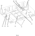
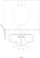
- FIG. 1 shows a robotic gripping system 10 for moving a workpiece 12, according to two embodiments.
- robotic gripping system 10 includes a robot arm 20, an EOAT 24 mounted to robot arm 20, a set of jaws 28 (or simply, jaws 28) for gripping workpiece 12, an optional jaw holder 30 atop which jaws 28 are stowed, and a vise 32.
- Jaws 28 are sharable between arm 20 and vise 32 because they include mechanical coupling interfaces on two perpendicular sides of jaws 28.
- a first interface 36 FIG. 4 , e.g., ridges and dovetails
- a second, low-profile interface 42 ( FIG. 3 ) is for EOAT 24 and is a subject of subsequent paragraphs in this disclosure.
- a set of part-gripping fingers 46 are included as a substitute for, or in addition to, jaws 28.
- Jaws 28 and fingers 46 provide for different part-gripping orientations relative to a grip axis.
- jaws 28 grip workpiece 12 in a first orientation relative to a grip axis of jaws 28
- fingers 46 grip workpiece 12 in a second orientation (different from the first orientation) relative to a grip axis of fingers 46.
- first orientation opposing first and second flat sides of workpiece 12 are, respectively, confronting and opposing a recessed datum 48 such that the flat sides are substantially parallel with a plane defined by datum 48.
- fingers 46 grip workpiece 12 in a transverse orientation, according to one embodiment. Skilled persons will appreciate, however, that finger 46 may grip another workpiece in the aforementioned first orientation.
- jaws and fingers are preferred. Accordingly, non-shared jaws need not include first interface 36 or may include a simplified interface suitable for stowing fingers 46 atop jaw holder 30. Some further applications may employ both shared and non-shared jaws, as contemplated in system 10 of FIG. 1 .
- jaws 28 are identical to fingers 46, datum 48 of jaws 28 are optional and may instead by an aperture such that modified jaws more closely resemble fingers. Therefore, for conciseness, the term jaws is used synonymously with the term fingers, unless contexts makes clear that the pertinent passages refer exclusively to sharable jaws.
- FIG. 2 is a partly exploded view detailing components of EOAT 24.
- EOAT 24 includes a mounting plate 58, gripper actuator 60, and a set of EOAT-to-gripper interface bodies 62 that are actuatable along a gripping axis.
- Bolts 64 attach bodies 62 to gripper actuator 60.
- Other bolts (not shown) attach mounting plate 58 to robot arm 20 and gripper actuator 60 to mounting plate 58.
- EOAT-to-gripper interface bodies 62 include a first body 66 and a second body 68, which are essentially mirror images of each other in the present embodiment. For conciseness, therefore, only jaw interface 70 of body 68 are described because identical features appear on body 66. As indicated in the preceding paragraph, other embodiments may include a single (i.e., non-centering) interface having no mirror-image counterpart.
- Jaw interface 70 include a Z-locating pocket 74 in the form of a laterally extending channel that guides jaws 28 or fingers 46 into Z-axis (i.e.., vertical) alignment, an alignment pin 76 projecting from a central contact surface pad 78, and spaced-apart female dovetails 80 to apply grip and release forces in an X-axis (along a gripping axis) direction.
- Each one of female dovetails 80 includes an ID dovetail edge 84 and an OD dovetail edge 88. Other shapes for joint, pin, and pocket are possible.
- female dovetails 80 could be substituted with male dovetails.
- dovetails need not form a complete joint in the sense that the term "dovetail" might be understood for joinery techniques. Specifically, one side of a female dovetail need not contact a confronting joint surface, as explained in the gripping applications described below, so a complete joinery dovetail need not be formed.
- lateral restraint dovetail joint surface to generically refer to angled surfaces (male or female) of the types shown in the accompanying figures that are configured to slidably confront oppositely angled surfaces when a lateral grip force is applied such that the two supplementary angled surfaces act to pull inward toward each other in response to the sliding forces.
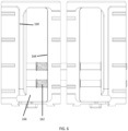
- FIGS. 3 and 4 show jaws 28 in greater detail.
- Jaws 28 include a first jaw body 90 and a second jaw body 92, which are generally mirror images in FIG. 3 . Accordingly, although the following description is of first jaw body 90, it applies to second jaw body 92.
- datum 48 is recessed in a surface 102.
- a sidewall 104 between datum 48 and surface 102 provides a part-gripping profile surface 106 to confront and engage a complementary OD surface profiled portion of workpiece 12 ( FIG. 1 ) as a grip force is applied to jaws 28 via interface 42 or interface 36 ( FIG. 4 ).
- EOAT interface 42 of jaws 28 includes a Z-locating boss 108 sized to fit within Z-locating pocket 74 of jaw interface 70 ( FIG. 2 ), an alignment window 110 for receiving pin 76 ( FIG. 2 ) and defining a face 112 that catches pin 76.
- alignment window 110 catches pin 76 to limit lateral expansion of first body 66 and second body 68 during EOAT 24 engagement of jaws 28, i.e., while coupling two spaced-apart male dovetails 114 sized to fit in corresponding female dovetails 80.
- male dovetails 114 each include an outward-facing OD edge 120 and need not include inward facing ID edges (c.f., edge 120 of FIG. 3 and edge 156 of FIG. 5 ).
- alignment pin 76 and alignment window 110 could be reversed such that an alignment pin is located on jaws 28 and an alignment window is located on EOAT interface 42. These terms are generically referred to as matable alignment structures. Likewise, Z-locating pocket 74 and Z-locating boss 108 are reversible. These terms are generically referred to as matable Z-locating structures
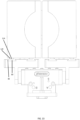
- FIG. 4 shows additional details of interface 36, which is a subject of the '395 patent.
- intermediate-jaw dovetail edges 124 are sloped and complementary to surfaces of intermediate jaws 40 ( FIG. 1 ), thereby acting as a Z-axis restraint and as a means to transfer clamping forces applied in an X-axis direction.
- Gear-like ridges 126 restrain Y-axis movement when mated with grooves of jaws 40. Additional details of interface 36 may be found in the '395 patent.
- FIG. 4 also shows a spring-actuated tensioner that applies a spring force to jaws 28 so as to maintain a securing force to edges 120 (i.e., to keep jaws 28 secured on EOAT 24) or to intermediate-jaw dovetail edges 124 (i.e., to keep jaws 28 secured on intermediate jaws 40, FIG. 1 ).
- FIGS. 5 and 6 show another set of jaw 150, which is similar to jaws 28.
- jaws 150 are for an ID clamping application.
- jaws 150 instead of including a recessed datum, jaws 150 include a raised part-gripping profile 152.
- clamping force acts to separate jaws, faces 154, dovetail edges 156, and vise edges 160 ( FIG. 6 ) all face in an opposite direction compared to that of the corresponding components of jaws 28.
- springs 162 are also configured to apply spring force to an inside surface 164 of cross pin pocket 166; forcing the jaws together.
- Fingers 46 also include an inner face 172 having a t-slot groove 174 configured to accept adjustable finger segments 176, which are generally symmetrical in the present embodiment.
- Each one of segments 176 includes a male-T connector 180 (which may be female when reversed), a bolt hole 182 configured to accept a set bolt 184 and nut 186.
- Nut 186 is configured to slide into t-slot groove 174 so that adjustable finger segments 176 can be adjusted into position and then locked into place by securing bolt 184 against nut 186.
- Adjustable finger segments 176 are configured with a fingertip mounting slot 192 and a fingertip mounting aperture 190 for securing fingertips 194.
- Fingertips 194 include a boss with receptacle 196 that is configured to mate into fingertip mounting slots 192 and align boss with receptacle 196 with fingertip mounting aperture 190.
- One side of fingertip mounting aperture 190 is configured as a clearance hole for a shoulder bolt 198 and the other end of the fingertip mounting aperture 190 is threaded to accept shoulder bolt 198 threads; fingertip mounting slot 192 acting as the mating surface for the shoulder of shoulder bolt 198.
- the relationship between the boss with receptacle 196 and fingertip mounting slot 192 is configured to create a small gap 218 between fingertips 194 and adjustable finger segments 176 that allows fingertips 194 to rock back and forth a small amount. Allowing one or both of fingertips 194 to rock back and forth allows fingers 46 to accommodate some flex in fingers 46 and parts that are not perfectly parallel. Fingertip leveling holes 191 accept optional set screws 193, allowing set screws 193 to be adjusted into contact with fingertips 194 limiting the fingertip rocking travel or locking fingertips 194 into an angle with respect to adjustable finger segments 176.
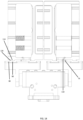
- FIGS. 9-16 show in succession how EOAT 24 engages jaws 28. In other words, these figures show how interfaces 42 and 70 are mated.
- FIGS. 13 and 14 show a second engagement step.
- EOAT 24 has moved into partial engagement with jaw 28 and with Z-locating boss 108 partially engaged with Z-locating pocket 74.
- EOAT 24 has been signaled to open.
- openings of female dovetails 80 are slightly away from and its edges 88 now aligned with edges 120 of male dovetails 114 of jaws 28.
- FIG. 14 also shows alignment pins 76 engaged with alignment faces 112.
- alignment pins 76 contact corresponding faces 112 to limit the opening travel of EOAT 24.
- the position of alignment pins 76 and alignment faces 112 are configured such that when alignment pins 76 contacts alignment faces 112, male dovetails 114 become aligned and centered in openings of female dovetails 80.
- FIG. 15 shows a third engagement step.
- EOAT 24 is in the partially open and aligned position and moved towards jaws 28 so that male dovetails 114 are inside of female dovetails 80.
- typically EOAT 24 would float (no opening force or closing force) to minimize friction between alignment pins 76 and alignment faces 112 as EOAT 24 is moved inwards towards jaws 28.
- Edges 88 clear and confront edges 120.
- FIG. 16 shows a fourth engagement step.
- EOAT 24 is clamped towards the closed position and female dovetail edge 88 is engaged with the OD male dovetail edge 120 of the jaws 28.
- the OD female dovetail edge 88 is applying a force to OD male dovetail edge 120 of jaws 28, thereby urging jaws 28 together to provide a clamping force to hold workpiece 12.
- the first step is to position EOAT 24 with jaws 28 over jaw holder 30 or vise 32 such that ridges 126 of jaws 28 are aligned with those of jaw holder 30 or vise 32 with EOAT 24 in a closed or OD clamped position and if engaging vise 32, it is in the open position.
- the third step is that vise 32 be closed, allowing vise OD dovetails to capture jaw OD dovetails 124. If disengaging jaws 28 to a jaw holder 30, the third step is skipped.
- the fourth step is to open EOAT 24 opened. If engaging jaw holder 30, this step allows jaws 28 to open against force of springs 142 so that jaws OD vise dovetails 124 engage jaw holder 30 OD jaw dovetails.
- the opening of EOAT 24 allows the bodies 62 ( FIG. 2 ) to open until alignment pins 76 come into contact with alignment faces 112 causing the opening of EOAT 24 female dovetails 80 to be aligned and centered with male dovetails 114.
- the fifth step is to float EOAT 24 and then to move IT away from jaws 28.
- step two EOAT 24 is sent a closing signal for jaws 150.
- alignment pins 76 engage with alignment face 154 ( FIG. 5 ) causing edges 84 ( FIG. 2 ) to be aligned with edges 156.
- step four EOAT 24 is opened allowing ID female dovetail edges 84 to engage with the ID male dovetail edges 156.
- a person may also engage or disengage by hand, jaws 28 onto EOAT 24, vise 32 or jaw holder 30.
- jaws 8 configured for OD clamping with jaw holder 30 or vise 32
- the person pushes jaws 28 closed and the places jaws 28 over jaw holder 30 or vise 32 so as to align and engage jaw holder 30 or vise 32 angled ridges with jaw 28 angled ridges 126 and then release jaws 28 so as to allow the force of the springs 142 to engage the OD vise dovetail with OD jaw dovetail 124.
- the operator pushes jaws 28 closed and then lifts jaws 28 away from jaw holder 30 or vise 32.
- jaws 28 to engage jaws 28 with EOAT 24, the person pushes jaws 28 together until the male dovetails are aligned with the female dovetails, aligns Z boss with the Z locating pocket, pushes the jaws so that the male dovetail is inside the female dovetail and then allows the jaws to open allowing the spring force to secure the male dovetail into the female dovetail.
- ID jaws 150 Hand engaging and disengaging ID jaws 150 is similar except ID jaws 150 are pulled apart to engage or disengage.
- To engage or disengage OD jaws 28 or ID jaws 150 on jaw holder 30 is similar to engaging or disengaging with vise 32 with the exception that there is no opening or closing of the vise step.
- the steps for engaging and disengaging jaws 150 configured for ID clamping is similar except EOAT 24 or vise 32 begins in the closed position and jaws 150 are pulled apart to place over an ID jaw dovetail of jaw holder 30 or vise 32 or to align the male dovetail of jaws 150 with female dovetail of EOAT 24 during engagement and disengagement
Landscapes
- Engineering & Computer Science (AREA)
- Robotics (AREA)
- Mechanical Engineering (AREA)
- Manipulator (AREA)
Claims (15)
- Une interface mécanique d'outil d'extrémité de bras (EOAT, End-Of Arm-Tool) pour coupler de façon opérationnelle un actionneur de préhenseur (60) à un dispositif de préhension de pièce, l'interface mécanique d'EOAT comprenant :des premier et deuxième corps d'interface (62) EOAT/préhenseur mobiles l'un par rapport à l'autre le long d'un axe de préhension, chacun des premier et deuxième corps d'interface (62) EOAT/préhenseur étant montable, respectivement, sur des première et deuxième portions de l'actionneur de préhenseur (60) qui est configuré pour actionner les premier et deuxième corps d'interface (62) EOAT/préhenseur le long de l'axe de préhension ;une surface d'assemblage à queue d'aronde de retenue latérale configurée pour entrer en contact et glisser par rapport à une surface d'assemblage à queue d'aronde de retenue latérale lui faisant face du dispositif de préhension de pièce en réponse à l'actionnement des premier et deuxième corps d'interface (62) EOAT/préhenseur, tirant ainsi le dispositif de préhension de pièce vers l'intérieur vers l'interface mécanique d'EOAT ; etune structure d'alignement accouplable configurée pour limiter une distance d'axe de préhension que l'actionneur de préhenseur ouvre lorsqu'il met en prise l'interface mécanique d'EOAT avec le dispositif de préhension de pièce de telle sorte que la surface d'assemblage à queue d'aronde de retenue latérale s'aligne pour une mise en prise avec la surface d'assemblage à queue d'aronde de retenue latérale lui faisant face.
- L'interface mécanique d'EOAT de la revendication 1, comprenant en outre une structure de positionnement sur axe Z accouplable avec une structure de positionnement sur axe Z lui faisant face du dispositif de préhension de pièce.
- L'interface mécanique d'EOAT de la revendication 2, dans laquelle la structure de positionnement sur axe Z inclut une poche de positionnement sur Z (74).
- L'interface mécanique d'EOAT de la revendication 2, dans laquelle la structure de positionnement sur axe Z inclut un bossage de positionnement sur Z (108).
- L'interface mécanique d'EOAT de la revendication 1, dans laquelle la structure d'alignement accouplable inclut une goupille d'alignement (76).
- L'interface mécanique d'EOAT de la revendication 1, dans laquelle la structure d'alignement accouplable inclut une fenêtre d'alignement (110).
- L'interface mécanique d'EOAT de la revendication 1, comprenant en outre une queue d'aronde femelle (80) incluant la surface d'assemblage à queue d'aronde de retenue latérale.
- L'interface mécanique d'EOAT de la revendication 1, comprenant en outre une queue d'aronde mâle (114) incluant la surface d'assemblage à queue d'aronde de retenue latérale.
- L'interface mécanique d'EOAT de n'importe laquelle des revendications 1 à 8, dans laquelle le premier corps d'interface (66) EOAT/préhenseur inclut la surface d'assemblage à queue d'aronde de retenue latérale et la structure d'alignement accouplable, et dans laquelle le deuxième corps d'interface (68) EOAT/préhenseur est une image-miroir du premier corps d'interface EOAT/préhenseur.
- Une interface mécanique de dispositif de préhension de pièce pour coupler de façon opérationnelle un outil d'extrémité de bras (EOAT) (24) à un dispositif de préhension de pièce, l'interface mécanique de dispositif de préhension de pièce comprenant :des premier et deuxième corps de mâchoire (28) mobiles l'un par rapport à l'autre le long d'un axe de préhension, chacun des premier et deuxième corps de mâchoire (28) étant montable, respectivement, sur des première et deuxième interfaces mécaniques d'EOAT de l'EOAT ;une surface d'assemblage à queue d'aronde de retenue latérale configurée pour entrer en contact et glisser par rapport à une surface d'assemblage à queue d'aronde de retenue latérale lui faisant face en réponse à l'actionnement des première et deuxième interfaces mécaniques d'EOAT, tirant ainsi le dispositif de préhension de pièce vers l'intérieur vers l'EOAT ; etun tensionneur actionné par ressort couplé aux premier et deuxième corps d'interface EOAT/préhenseur et configuré pour maintenir une force d'assujettissement appliquée le long de l'axe de préhension sur la surface d'assemblage à queue d'aronde de retenue latérale.
- L'interface mécanique de dispositif de préhension de pièce de la revendication 10, comprenant en outre une structure de positionnement sur axe Z accouplable avec une structure de positionnement sur axe Z lui faisant face du dispositif de préhension de pièce, facultativement où la structure de positionnement sur axe Z inclut une poche de positionnement sur Z (74) d'un bossage de positionnement sur Z (108).
- L'interface mécanique de dispositif de préhension de pièce de la revendication 10, comprenant en outre une structure d'alignement accouplable configurée pour limiter une distance d'axe de préhension qu'un actionneur de préhenseur (60) ouvre lorsqu'il se met en prise avec l'interface mécanique de dispositif de préhension de pièce de telle sorte que la surface d'assemblage à queue d'aronde de retenue latérale s'aligne avec la surface d'assemblage à queue d'aronde de retenue latérale lui faisant face.
- L'interface mécanique de dispositif de préhension de pièce de la revendication 12, dans laquelle la structure d'alignement accouplable inclut une goupille d'alignement (76) ou une fenêtre d'alignement (110).
- L'interface mécanique de dispositif de préhension de pièce de la revendication 10, comprenant en outre une queue d'aronde femelle (80) ou une queue d'aronde mâle (114), incluant la surface d'assemblage à queue d'aronde de retenue latérale.
- L'interface mécanique de dispositif de préhension de pièce de n'importe laquelle des revendications 10 à 14, dans laquelle le deuxième corps de mâchoire (68) est une image-miroir de la première mâchoire (66).
Applications Claiming Priority (2)
| Application Number | Priority Date | Filing Date | Title |
|---|---|---|---|
| US201962896644P | 2019-09-06 | 2019-09-06 | |
| PCT/US2020/049579 WO2021046479A1 (fr) | 2019-09-06 | 2020-09-04 | Système de préhension robotique |
Publications (3)
| Publication Number | Publication Date |
|---|---|
| EP4007675A1 EP4007675A1 (fr) | 2022-06-08 |
| EP4007675A4 EP4007675A4 (fr) | 2023-08-16 |
| EP4007675B1 true EP4007675B1 (fr) | 2024-10-23 |
Family
ID=74853058
Family Applications (1)
| Application Number | Title | Priority Date | Filing Date |
|---|---|---|---|
| EP20859843.3A Active EP4007675B1 (fr) | 2019-09-06 | 2020-09-04 | Système de préhension robotique |
Country Status (3)
| Country | Link |
|---|---|
| US (1) | US12447632B2 (fr) |
| EP (1) | EP4007675B1 (fr) |
| WO (1) | WO2021046479A1 (fr) |
Families Citing this family (5)
| Publication number | Priority date | Publication date | Assignee | Title |
|---|---|---|---|---|
| CN111093891B (zh) | 2017-04-27 | 2022-08-02 | 磁转换技术全球私人有限公司 | 具有至少一个传感器布置和消磁能力的磁耦合装置 |
| US10903030B2 (en) | 2017-04-27 | 2021-01-26 | Magswitch Technology Worldwide Pty Ltd. | Variable field magnetic couplers and methods for engaging a ferromagnetic workpiece |
| DE102018106210A1 (de) * | 2018-03-16 | 2019-09-19 | Gressel Ag | Greif- und Positioniereinrichtung zum Transport einer Spannvorrichtung zwischen unterschiedlichen Positionen |
| US12552048B2 (en) | 2021-06-11 | 2026-02-17 | Magswitch Automation Company | Component handling systems and methods |
| WO2022261520A1 (fr) | 2021-06-11 | 2022-12-15 | Magswitch Technology, Inc. | Organe effecteur ou dispositif de fixation réglable |
Family Cites Families (10)
| Publication number | Priority date | Publication date | Assignee | Title |
|---|---|---|---|---|
| US4852242A (en) * | 1988-03-24 | 1989-08-01 | Hewlett-Packard Company | Tool coupling apparatus and method |
| JP2568012B2 (ja) * | 1991-07-31 | 1996-12-25 | 株式会社三協精機製作所 | チャック装置 |
| US5360249A (en) | 1991-09-13 | 1994-11-01 | Refac Technology Development, Corporation | Multifunctional end effectors |
| JP2010214510A (ja) * | 2009-03-16 | 2010-09-30 | Denso Corp | 柱状体の搬送用チャック |
| JP6272629B2 (ja) | 2013-04-29 | 2018-01-31 | リクルス モーター スポーツ,インコーポレーテッド | ロボットテンダーを用いて種々の部品形状を保管し処理するシステム及び方法 |
| US9855663B1 (en) * | 2016-06-17 | 2018-01-02 | X Development Llc | Automated digit interchange |
| CN106553003A (zh) * | 2016-11-30 | 2017-04-05 | 湖州佳创自动化科技有限公司 | 一种激光切割中的双定位装置 |
| US10994423B2 (en) * | 2018-06-15 | 2021-05-04 | Delaware Capital Formation, Inc. | Gripper with a trident body section |
| DE102019117458A1 (de) * | 2019-06-28 | 2020-12-31 | Schaeffler Technologies AG & Co. KG | Schnellwechselsystem |
| KR20230131618A (ko) * | 2022-03-07 | 2023-09-14 | 주식회사 엘지에너지솔루션 | 셀 패키징 장치 |
-
2020
- 2020-09-04 EP EP20859843.3A patent/EP4007675B1/fr active Active
- 2020-09-04 US US17/753,396 patent/US12447632B2/en active Active
- 2020-09-04 WO PCT/US2020/049579 patent/WO2021046479A1/fr not_active Ceased
Also Published As
| Publication number | Publication date |
|---|---|
| EP4007675A4 (fr) | 2023-08-16 |
| EP4007675A1 (fr) | 2022-06-08 |
| US20220297315A1 (en) | 2022-09-22 |
| WO2021046479A1 (fr) | 2021-03-11 |
| US12447632B2 (en) | 2025-10-21 |
Similar Documents
| Publication | Publication Date | Title |
|---|---|---|
| EP4007675B1 (fr) | Système de préhension robotique | |
| US5044063A (en) | Robotic tool change mechanism | |
| US12048978B2 (en) | Robotic tool changer system and method for performing tool change with robotic tool changer system | |
| US4715636A (en) | Gripper including an exchangeable gripping jaw | |
| US7513546B2 (en) | Conformal gripping device | |
| US20210008644A1 (en) | Hand for exchanging claws of a chuck, method for automatically exchanging claws of a chuck, and system for automatically exchanging claws | |
| EP1452273B1 (fr) | Unité pour ajuster la force de serrage pour un étau | |
| US12397448B2 (en) | Tool changer for a robot and changing system therefor | |
| US11679513B2 (en) | End effector exchange device | |
| CN109982817B (zh) | 机器人处理系统 | |
| US5219318A (en) | Spline screw autochanger | |
| JP7366560B2 (ja) | 産業用マニピュレータ用のダブテールツールチェンジャー | |
| WO2018211867A1 (fr) | Dispositif de préhension de pièce à usiner | |
| CN111095691B (zh) | 电缆处理设备 | |
| KR20230052911A (ko) | 물체들의 홀딩, 클램핑 및 포지셔닝을 위한 시스템 | |
| TWM575741U (zh) | Jaw device and memory card testing device | |
| JPH02258124A (ja) | 板材位置決め装置 | |
| US4546988A (en) | Chuck top jaw with removable insert | |
| GB2191466A (en) | Robotic gripper | |
| JPH0866870A (ja) | バイス | |
| JP4092839B2 (ja) | 移動体のロック装置 | |
| SU891327A2 (ru) | Захват | |
| JPH03121728A (ja) | ボルト挿入装置 | |
| JPH06143014A (ja) | チャック爪の保持ハンド |
Legal Events
| Date | Code | Title | Description |
|---|---|---|---|
| STAA | Information on the status of an ep patent application or granted ep patent |
Free format text: STATUS: THE INTERNATIONAL PUBLICATION HAS BEEN MADE |
|
| PUAI | Public reference made under article 153(3) epc to a published international application that has entered the european phase |
Free format text: ORIGINAL CODE: 0009012 |
|
| STAA | Information on the status of an ep patent application or granted ep patent |
Free format text: STATUS: REQUEST FOR EXAMINATION WAS MADE |
|
| 17P | Request for examination filed |
Effective date: 20220301 |
|
| AK | Designated contracting states |
Kind code of ref document: A1 Designated state(s): AL AT BE BG CH CY CZ DE DK EE ES FI FR GB GR HR HU IE IS IT LI LT LU LV MC MK MT NL NO PL PT RO RS SE SI SK SM TR |
|
| DAV | Request for validation of the european patent (deleted) | ||
| DAX | Request for extension of the european patent (deleted) | ||
| A4 | Supplementary search report drawn up and despatched |
Effective date: 20230717 |
|
| RIC1 | Information provided on ipc code assigned before grant |
Ipc: B25J 15/04 20060101ALI20230711BHEP Ipc: B25J 15/02 20060101ALI20230711BHEP Ipc: B25J 15/00 20060101ALI20230711BHEP Ipc: B25J 15/08 20060101ALI20230711BHEP Ipc: B23Q 5/10 20060101ALI20230711BHEP Ipc: B23Q 3/10 20060101ALI20230711BHEP Ipc: B23Q 3/06 20060101AFI20230711BHEP |
|
| GRAP | Despatch of communication of intention to grant a patent |
Free format text: ORIGINAL CODE: EPIDOSNIGR1 |
|
| STAA | Information on the status of an ep patent application or granted ep patent |
Free format text: STATUS: GRANT OF PATENT IS INTENDED |
|
| INTG | Intention to grant announced |
Effective date: 20240527 |
|
| RIN1 | Information on inventor provided before grant (corrected) |
Inventor name: BLAINE, BENJAMIN THOMAS Inventor name: YOUNGWERTH, ALEXANDER D Inventor name: YOUNGWERTH, ALBERT JAMES |
|
| GRAS | Grant fee paid |
Free format text: ORIGINAL CODE: EPIDOSNIGR3 |
|
| GRAA | (expected) grant |
Free format text: ORIGINAL CODE: 0009210 |
|
| STAA | Information on the status of an ep patent application or granted ep patent |
Free format text: STATUS: THE PATENT HAS BEEN GRANTED |
|
| AK | Designated contracting states |
Kind code of ref document: B1 Designated state(s): AL AT BE BG CH CY CZ DE DK EE ES FI FR GB GR HR HU IE IS IT LI LT LU LV MC MK MT NL NO PL PT RO RS SE SI SK SM TR |
|
| REG | Reference to a national code |
Ref country code: GB Ref legal event code: FG4D |
|
| REG | Reference to a national code |
Ref country code: CH Ref legal event code: EP |
|
| REG | Reference to a national code |
Ref country code: DE Ref legal event code: R096 Ref document number: 602020040066 Country of ref document: DE |
|
| REG | Reference to a national code |
Ref country code: IE Ref legal event code: FG4D |
|
| REG | Reference to a national code |
Ref country code: LT Ref legal event code: MG9D |
|
| REG | Reference to a national code |
Ref country code: NL Ref legal event code: MP Effective date: 20241023 |
|
| REG | Reference to a national code |
Ref country code: AT Ref legal event code: MK05 Ref document number: 1734458 Country of ref document: AT Kind code of ref document: T Effective date: 20241023 |
|
| PG25 | Lapsed in a contracting state [announced via postgrant information from national office to epo] |
Ref country code: NL Free format text: LAPSE BECAUSE OF FAILURE TO SUBMIT A TRANSLATION OF THE DESCRIPTION OR TO PAY THE FEE WITHIN THE PRESCRIBED TIME-LIMIT Effective date: 20241023 |
|
| PG25 | Lapsed in a contracting state [announced via postgrant information from national office to epo] |
Ref country code: NL Free format text: LAPSE BECAUSE OF FAILURE TO SUBMIT A TRANSLATION OF THE DESCRIPTION OR TO PAY THE FEE WITHIN THE PRESCRIBED TIME-LIMIT Effective date: 20241023 |
|
| PG25 | Lapsed in a contracting state [announced via postgrant information from national office to epo] |
Ref country code: IS Free format text: LAPSE BECAUSE OF FAILURE TO SUBMIT A TRANSLATION OF THE DESCRIPTION OR TO PAY THE FEE WITHIN THE PRESCRIBED TIME-LIMIT Effective date: 20250223 Ref country code: HR Free format text: LAPSE BECAUSE OF FAILURE TO SUBMIT A TRANSLATION OF THE DESCRIPTION OR TO PAY THE FEE WITHIN THE PRESCRIBED TIME-LIMIT Effective date: 20241023 Ref country code: PT Free format text: LAPSE BECAUSE OF FAILURE TO SUBMIT A TRANSLATION OF THE DESCRIPTION OR TO PAY THE FEE WITHIN THE PRESCRIBED TIME-LIMIT Effective date: 20250224 |
|
| PG25 | Lapsed in a contracting state [announced via postgrant information from national office to epo] |
Ref country code: FI Free format text: LAPSE BECAUSE OF FAILURE TO SUBMIT A TRANSLATION OF THE DESCRIPTION OR TO PAY THE FEE WITHIN THE PRESCRIBED TIME-LIMIT Effective date: 20241023 |
|
| PG25 | Lapsed in a contracting state [announced via postgrant information from national office to epo] |
Ref country code: BG Free format text: LAPSE BECAUSE OF FAILURE TO SUBMIT A TRANSLATION OF THE DESCRIPTION OR TO PAY THE FEE WITHIN THE PRESCRIBED TIME-LIMIT Effective date: 20241023 |
|
| PG25 | Lapsed in a contracting state [announced via postgrant information from national office to epo] |
Ref country code: ES Free format text: LAPSE BECAUSE OF FAILURE TO SUBMIT A TRANSLATION OF THE DESCRIPTION OR TO PAY THE FEE WITHIN THE PRESCRIBED TIME-LIMIT Effective date: 20241023 |
|
| PG25 | Lapsed in a contracting state [announced via postgrant information from national office to epo] |
Ref country code: NO Free format text: LAPSE BECAUSE OF FAILURE TO SUBMIT A TRANSLATION OF THE DESCRIPTION OR TO PAY THE FEE WITHIN THE PRESCRIBED TIME-LIMIT Effective date: 20250123 |
|
| PG25 | Lapsed in a contracting state [announced via postgrant information from national office to epo] |
Ref country code: LV Free format text: LAPSE BECAUSE OF FAILURE TO SUBMIT A TRANSLATION OF THE DESCRIPTION OR TO PAY THE FEE WITHIN THE PRESCRIBED TIME-LIMIT Effective date: 20241023 Ref country code: AT Free format text: LAPSE BECAUSE OF FAILURE TO SUBMIT A TRANSLATION OF THE DESCRIPTION OR TO PAY THE FEE WITHIN THE PRESCRIBED TIME-LIMIT Effective date: 20241023 Ref country code: GR Free format text: LAPSE BECAUSE OF FAILURE TO SUBMIT A TRANSLATION OF THE DESCRIPTION OR TO PAY THE FEE WITHIN THE PRESCRIBED TIME-LIMIT Effective date: 20250124 |
|
| PG25 | Lapsed in a contracting state [announced via postgrant information from national office to epo] |
Ref country code: PL Free format text: LAPSE BECAUSE OF FAILURE TO SUBMIT A TRANSLATION OF THE DESCRIPTION OR TO PAY THE FEE WITHIN THE PRESCRIBED TIME-LIMIT Effective date: 20241023 |
|
| PG25 | Lapsed in a contracting state [announced via postgrant information from national office to epo] |
Ref country code: RS Free format text: LAPSE BECAUSE OF FAILURE TO SUBMIT A TRANSLATION OF THE DESCRIPTION OR TO PAY THE FEE WITHIN THE PRESCRIBED TIME-LIMIT Effective date: 20250123 |
|
| PG25 | Lapsed in a contracting state [announced via postgrant information from national office to epo] |
Ref country code: SM Free format text: LAPSE BECAUSE OF FAILURE TO SUBMIT A TRANSLATION OF THE DESCRIPTION OR TO PAY THE FEE WITHIN THE PRESCRIBED TIME-LIMIT Effective date: 20241023 |
|
| PG25 | Lapsed in a contracting state [announced via postgrant information from national office to epo] |
Ref country code: DK Free format text: LAPSE BECAUSE OF FAILURE TO SUBMIT A TRANSLATION OF THE DESCRIPTION OR TO PAY THE FEE WITHIN THE PRESCRIBED TIME-LIMIT Effective date: 20241023 |
|
| PG25 | Lapsed in a contracting state [announced via postgrant information from national office to epo] |
Ref country code: EE Free format text: LAPSE BECAUSE OF FAILURE TO SUBMIT A TRANSLATION OF THE DESCRIPTION OR TO PAY THE FEE WITHIN THE PRESCRIBED TIME-LIMIT Effective date: 20241023 |
|
| PG25 | Lapsed in a contracting state [announced via postgrant information from national office to epo] |
Ref country code: RO Free format text: LAPSE BECAUSE OF FAILURE TO SUBMIT A TRANSLATION OF THE DESCRIPTION OR TO PAY THE FEE WITHIN THE PRESCRIBED TIME-LIMIT Effective date: 20241023 |
|
| REG | Reference to a national code |
Ref country code: DE Ref legal event code: R097 Ref document number: 602020040066 Country of ref document: DE |
|
| PG25 | Lapsed in a contracting state [announced via postgrant information from national office to epo] |
Ref country code: SK Free format text: LAPSE BECAUSE OF FAILURE TO SUBMIT A TRANSLATION OF THE DESCRIPTION OR TO PAY THE FEE WITHIN THE PRESCRIBED TIME-LIMIT Effective date: 20241023 |
|
| PG25 | Lapsed in a contracting state [announced via postgrant information from national office to epo] |
Ref country code: CZ Free format text: LAPSE BECAUSE OF FAILURE TO SUBMIT A TRANSLATION OF THE DESCRIPTION OR TO PAY THE FEE WITHIN THE PRESCRIBED TIME-LIMIT Effective date: 20241023 |
|
| PG25 | Lapsed in a contracting state [announced via postgrant information from national office to epo] |
Ref country code: IT Free format text: LAPSE BECAUSE OF FAILURE TO SUBMIT A TRANSLATION OF THE DESCRIPTION OR TO PAY THE FEE WITHIN THE PRESCRIBED TIME-LIMIT Effective date: 20241023 |
|
| PLBE | No opposition filed within time limit |
Free format text: ORIGINAL CODE: 0009261 |
|
| STAA | Information on the status of an ep patent application or granted ep patent |
Free format text: STATUS: NO OPPOSITION FILED WITHIN TIME LIMIT |
|
| PG25 | Lapsed in a contracting state [announced via postgrant information from national office to epo] |
Ref country code: SE Free format text: LAPSE BECAUSE OF FAILURE TO SUBMIT A TRANSLATION OF THE DESCRIPTION OR TO PAY THE FEE WITHIN THE PRESCRIBED TIME-LIMIT Effective date: 20241023 |
|
| 26N | No opposition filed |
Effective date: 20250724 |
|
| PGFP | Annual fee paid to national office [announced via postgrant information from national office to epo] |
Ref country code: DE Payment date: 20250702 Year of fee payment: 6 |