EP4007943B1 - Surveillance d'état de transducteur piézoélectrique - Google Patents
Surveillance d'état de transducteur piézoélectrique Download PDFInfo
- Publication number
- EP4007943B1 EP4007943B1 EP19797842.2A EP19797842A EP4007943B1 EP 4007943 B1 EP4007943 B1 EP 4007943B1 EP 19797842 A EP19797842 A EP 19797842A EP 4007943 B1 EP4007943 B1 EP 4007943B1
- Authority
- EP
- European Patent Office
- Prior art keywords
- piezoelectric transducer
- voltage
- peak
- response signal
- pulse
- Prior art date
- Legal status (The legal status is an assumption and is not a legal conclusion. Google has not performed a legal analysis and makes no representation as to the accuracy of the status listed.)
- Active
Links
Images




Classifications
-
- G—PHYSICS
- G05—CONTROLLING; REGULATING
- G05B—CONTROL OR REGULATING SYSTEMS IN GENERAL; FUNCTIONAL ELEMENTS OF SUCH SYSTEMS; MONITORING OR TESTING ARRANGEMENTS FOR SUCH SYSTEMS OR ELEMENTS
- G05B23/00—Testing or monitoring of control systems or parts thereof
- G05B23/02—Electric testing or monitoring
- G05B23/0205—Electric testing or monitoring by means of a monitoring system capable of detecting and responding to faults
- G05B23/0218—Electric testing or monitoring by means of a monitoring system capable of detecting and responding to faults characterised by the fault detection method dealing with either existing or incipient faults
- G05B23/0256—Electric testing or monitoring by means of a monitoring system capable of detecting and responding to faults characterised by the fault detection method dealing with either existing or incipient faults injecting test signals and analyzing monitored process response, e.g. injecting the test signal while interrupting the normal operation of the monitored system; superimposing the test signal onto a control signal during normal operation of the monitored system
-
- B—PERFORMING OPERATIONS; TRANSPORTING
- B06—GENERATING OR TRANSMITTING MECHANICAL VIBRATIONS IN GENERAL
- B06B—METHODS OR APPARATUS FOR GENERATING OR TRANSMITTING MECHANICAL VIBRATIONS OF INFRASONIC, SONIC, OR ULTRASONIC FREQUENCY, e.g. FOR PERFORMING MECHANICAL WORK IN GENERAL
- B06B1/00—Methods or apparatus for generating mechanical vibrations of infrasonic, sonic, or ultrasonic frequency
- B06B1/02—Methods or apparatus for generating mechanical vibrations of infrasonic, sonic, or ultrasonic frequency making use of electrical energy
- B06B1/0207—Driving circuits
- B06B1/0215—Driving circuits for generating pulses, e.g. bursts of oscillations, envelopes
-
- G—PHYSICS
- G01—MEASURING; TESTING
- G01F—MEASURING VOLUME, VOLUME FLOW, MASS FLOW OR LIQUID LEVEL; METERING BY VOLUME
- G01F1/00—Measuring the volume flow or mass flow of fluid or fluent solid material wherein the fluid passes through a meter in a continuous flow
- G01F1/05—Measuring the volume flow or mass flow of fluid or fluent solid material wherein the fluid passes through a meter in a continuous flow by using mechanical effects
- G01F1/20—Measuring the volume flow or mass flow of fluid or fluent solid material wherein the fluid passes through a meter in a continuous flow by using mechanical effects by detection of dynamic effects of the flow
- G01F1/32—Measuring the volume flow or mass flow of fluid or fluent solid material wherein the fluid passes through a meter in a continuous flow by using mechanical effects by detection of dynamic effects of the flow using swirl flowmeters
- G01F1/325—Means for detecting quantities used as proxy variables for swirl
-
- G—PHYSICS
- G01—MEASURING; TESTING
- G01F—MEASURING VOLUME, VOLUME FLOW, MASS FLOW OR LIQUID LEVEL; METERING BY VOLUME
- G01F1/00—Measuring the volume flow or mass flow of fluid or fluent solid material wherein the fluid passes through a meter in a continuous flow
- G01F1/05—Measuring the volume flow or mass flow of fluid or fluent solid material wherein the fluid passes through a meter in a continuous flow by using mechanical effects
- G01F1/20—Measuring the volume flow or mass flow of fluid or fluent solid material wherein the fluid passes through a meter in a continuous flow by using mechanical effects by detection of dynamic effects of the flow
- G01F1/32—Measuring the volume flow or mass flow of fluid or fluent solid material wherein the fluid passes through a meter in a continuous flow by using mechanical effects by detection of dynamic effects of the flow using swirl flowmeters
- G01F1/325—Means for detecting quantities used as proxy variables for swirl
- G01F1/3287—Means for detecting quantities used as proxy variables for swirl circuits therefor
-
- G—PHYSICS
- G01—MEASURING; TESTING
- G01F—MEASURING VOLUME, VOLUME FLOW, MASS FLOW OR LIQUID LEVEL; METERING BY VOLUME
- G01F25/00—Testing or calibration of apparatus for measuring volume, volume flow or liquid level or for metering by volume
- G01F25/10—Testing or calibration of apparatus for measuring volume, volume flow or liquid level or for metering by volume of flowmeters
-
- G—PHYSICS
- G01—MEASURING; TESTING
- G01P—MEASURING LINEAR OR ANGULAR SPEED, ACCELERATION, DECELERATION, OR SHOCK; INDICATING PRESENCE, ABSENCE, OR DIRECTION, OF MOVEMENT
- G01P21/00—Testing or calibrating of apparatus or devices covered by the preceding groups
- G01P21/02—Testing or calibrating of apparatus or devices covered by the preceding groups of speedometers
- G01P21/025—Testing or calibrating of apparatus or devices covered by the preceding groups of speedometers for measuring speed of fluids; for measuring speed of bodies relative to fluids
-
- B—PERFORMING OPERATIONS; TRANSPORTING
- B06—GENERATING OR TRANSMITTING MECHANICAL VIBRATIONS IN GENERAL
- B06B—METHODS OR APPARATUS FOR GENERATING OR TRANSMITTING MECHANICAL VIBRATIONS OF INFRASONIC, SONIC, OR ULTRASONIC FREQUENCY, e.g. FOR PERFORMING MECHANICAL WORK IN GENERAL
- B06B2201/00—Indexing scheme associated with B06B1/0207 for details covered by B06B1/0207 but not provided for in any of its subgroups
- B06B2201/40—Indexing scheme associated with B06B1/0207 for details covered by B06B1/0207 but not provided for in any of its subgroups with testing, calibrating, safety devices, built-in protection, construction details
-
- B—PERFORMING OPERATIONS; TRANSPORTING
- B06—GENERATING OR TRANSMITTING MECHANICAL VIBRATIONS IN GENERAL
- B06B—METHODS OR APPARATUS FOR GENERATING OR TRANSMITTING MECHANICAL VIBRATIONS OF INFRASONIC, SONIC, OR ULTRASONIC FREQUENCY, e.g. FOR PERFORMING MECHANICAL WORK IN GENERAL
- B06B2201/00—Indexing scheme associated with B06B1/0207 for details covered by B06B1/0207 but not provided for in any of its subgroups
- B06B2201/50—Application to a particular transducer type
- B06B2201/55—Piezoelectric transducer
Definitions
- Embodiments of the present disclosure relate to industrial process field devices and, more specifically, to monitoring of piezoelectric transducers of an industrial process field device.
- WO 95/06259 A1 describes an apparatus for detecting the malfunctioning of an accelerometer.
- a a test signal in form of a pulse is transmitted from a test signal generator to the accelerometer by means of a change-over switch capable of performing a change in such a manner that the response signal from the accelerometer can be transmitted to an analyzing circuit so as to be subjected to a malfunction detection.
- the change-over switch is adapted to alternately connect the accelerometer either to the test signal generator or to the analyzing circuit.
- US 2019/250200 A1 describes a functional self-test for a piezoelectric element deployed in an end-product.
- An excitation signal is applied to a unit under test (UUT), the excitation signal including a cyclical signal for a first interval and substantially zero signal for a second interval.
- a frequency content of a UUT response signal is determined, and a fail result is generated in response to the frequency content below a predetermined threshold.
- JP 2003-329502 A describes an ultrasonic wave flowmeter detecting measurement errors and failures caused by changes in characteristics of ultrasonic wave oscillators.
- Industrial process field devices used in industrial process control and monitoring systems typically include a sensing element or transducer that responds to a process variable, and signal conditioning and processing circuitry to convert the sensed variable into a transmitter output that is a function of the sensed process variable.
- process variable refers to a physical or chemical state of matter or conversion of energy. Examples of process variables include pressure, temperature, flow, conductivity, PH, and other properties.
- Process transmitters are typically used to monitor process variables and send measurement values back to a control room in a chemical, petroleum, gas, pharmaceutical, or other fluid processing plant.
- piezoelectric transducer One common transducer used in industrial process field devices is a piezoelectric transducer. Piezoelectric transducers may be used to detect an applied force, such as one produced by motion or vibration of an object, to which the piezoelectric transducer is attached. Movement of the object causes the piezoelectric transducer to generate a voltage across terminals of the transducer, the magnitude of which corresponds to the degree of force applied to the transducer. Sensors formed using piezoelectric transducers may be configured to detect industrial process variables such as, for example, fluid flow rates.
- Piezoelectric transducers have the potential to malfunction or fail. Such a malfunction could result in faulty process variable measurements. Routine testing of the field device by a skilled technician could potentially assist in detecting a failing piezoelectric transducer of the device, but such testing may require the field device to be removed from service and transported to a testing facility.
- FIG. 1 is a simplified diagram of an exemplary industrial process measurement system 100, in accordance with embodiments of the present disclosure.
- the system 100 may be used in the processing of a material (e.g., process medium) to transform the material from a less valuable state into more valuable and useful products, such as petroleum, chemicals, paper, food, etc.
- a material e.g., process medium
- the system 100 may be used in an oil refinery that performs industrial processes that can process crude oil into gasoline, fuel oil, and other petrochemicals.
- the system 100 includes a field device 102 (e.g., a process transmitter) that utilizes a piezoelectric transducer 104 to sense a process variable, such as a variable relating to a process medium 106.
- the field device 102 includes communications circuit 108 for communicating with an external computerized control unit 110 over a suitable process control loop.
- the control unit 110 may be remotely located from the device 102, such as in a control room 112 for the system 100, as shown in FIG. 1 .
- the process control loop includes a physical communication link, such as a two-wire control loop 114, or a wireless communication link. Communications between the control unit 110, or another external computing device, and the field device 102 may be performed over the control loop 114 in accordance with conventional analog and/or digital communication protocols.
- the two-wire control loop 114 includes a 4-20 milliamp control loop, in which a process variable may be represented by a level of a loop current I flowing through the two-wire control loop 114.
- Exemplary digital communication protocols include the modulation of digital signals onto the analog current level of the two-wire control loop 114, such as in accordance with the HART ® communication standard. Other purely digital techniques may also be employed including FieldBus and Profibus communication protocols.
- Exemplary wireless versions of the process control loop include, for example, a wireless mesh network protocol, such as WirelessHART ® (IEC 62591) or ISA 100.11a (IEC 62734), or another wireless communication protocol, such as WiFi, LoRa, Sigfox, BLE, or any other suitable protocol.
- a wireless mesh network protocol such as WirelessHART ® (IEC 62591) or ISA 100.11a (IEC 62734)
- another wireless communication protocol such as WiFi, LoRa, Sigfox, BLE, or any other suitable protocol.
- Power may be supplied to the field device 102 from any suitable power source.
- the field device 102 may be wholly powered by the current I flowing through the control loop 114.
- One or more power supplies may also be utilized to power the field device 102, such as an internal or an external battery.
- An electrical power generator e.g., solar panel, a wind power generator, etc. may also be used to power the field device 102, or charge a power supply used by the field device 102.
- the device 102 includes a controller 120, which may represent one or more processors (i.e., microprocessor, microcontroller, central processing unit, etc.) that control components of the device 102 to perform one or more functions described herein in response to the execution of instructions, which may be stored locally in any suitable patent subject matter eligible computer readable media or memory 122 that does not include transitory waves or signals, such as, for example, hard disks, CD-ROMs, optical storage devices, or magnetic storage devices.
- the processors of the controller 120 may be components of one or more computer-based systems.
- the controller 120 includes one or more control circuits, microprocessor-based engine control systems, one or more programmable hardware components, such as a field programmable gate array (FPGA), that are used to control components of the device 102 to perform one or more functions described herein.
- FPGA field programmable gate array
- the piezoelectric transducer 104 may be used to perform any conventional function relating to industrial process field devices 102, such as a sensing function, in which the piezoelectric transducer 104 is used to sense a process variable relating to an industrial process, such as a process variable associated with a process medium 106.
- This sensing function may be facilitated using a sensor circuit 124 that operates the piezoelectric transducer 104 in a sensing mode, and generates a sensor signal 126 indicating the process variable based on a signal output from the piezoelectric transducer, such as a voltage across terminals of the piezoelectric transducer.
- the sensor signal 126 may be processed by the controller 120 and communicated to the control unit 110 or another external computing device using the communications circuit 108.
- piezoelectric transducers may degrade and fail, which can result in faulty process variable measurements.
- conventional field devices require direct testing of the field device by a technician, which may include transporting the field device to a testing facility. As a result, such periodic testing of the field devices can be costly and lead to significant downtime.
- test circuit 130 is used to operate the piezoelectric transducer 104 in a testing mode, in which one or more diagnostic tests may be performed on the piezoelectric transducer 104 to determine whether it is operating properly.
- the test circuit 130 outputs diagnostic information 132, which may be used by the controller 120 to determine a current condition of the piezoelectric transducer, and generate a diagnostic test result for the piezoelectric transducer 104.
- the diagnostic test result may indicate whether the piezoelectric transducer 104 is operating properly (e.g., within a normal operating range) or abnormally.
- the controller may also communicate the diagnostic test result to the control unit 110 or another external computing device using the communications circuit 108 over the process control loop (e.g., physical or wireless communication link).
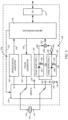
- FIG. 2 is a flowchart illustrating an exemplary method for testing a condition of a piezoelectric transducer 104 of an industrial process field device 102, in accordance with embodiments of the present disclosure.
- Embodiments of the method may refer to FIGS. 3 and 4 , which are simplified diagrams of circuitry comprising an exemplary sensor circuit 124 and an exemplary test circuit 130, with the piezoelectric transducer respectively operating in sensing and testing modes, in accordance with embodiments of the present disclosure.
- the piezoelectric transducer 104 is operated in a sensing mode ( FIG. 3 ) using the sensor circuit 124 of the field device 102. This involves generating the sensor signal 126 that indicates the process variable based on a voltage across the piezoelectric transducer 104, such as across terminals 142 and 144 of the piezoelectric transducer 104.
- the terminal 144 of the piezoelectric transducer 104 is connected to electrical ground 146, and the terminal 142 is connected to a sensor signal amplifier 148 of the sensor circuit 124, as indicated in FIG. 3 .
- the sensor signal amplifier 148 may be any suitable amplifier for use with piezoelectric transducers to amplify the voltage signal (sensor signal) across the piezoelectric transducer 104 that indicates the sensed process variable.
- the sensor signal amplifier 148 may include signal amplifying circuits, analog-to-digital converters, and other conventional components for translating the voltage signal across the piezoelectric transducer 104 into a form that may be used by a microcontroller 150 or the controller 120 to discern the process variable measurement.
- the microcontroller 150 may communicate the sensor signal 126, or the value represented thereby, through a suitable input/output component 152, as indicated in FIG. 3 .
- the piezoelectric transducer 104 generates the sensor signal based on the process variable being detected.
- the sensor signal may be amplified by the sensor signal amplifier 148 and provided to the microcontroller 150.
- the microcontroller 150 may perform additional processing of the sensor signal 126, and may communicate the sensor signal 126, or a corresponding value indicated by the sensor signal 126, to the controller 120 of the device 102, as indicated by the sensor signal 126 in FIG. 1 .
- the controller 120 may then communicate the sensor signal 126, or the value indicated by the sensor signal 126, to the control unit 110 or another external computing device.
- the piezoelectric transducer 104 or the device 102 is operated in a testing mode ( FIG. 4 ) using the test circuit 130 of the field device 102.
- the terminal 142 of the piezoelectric transducer 104 is coupled to a pulse generator 162 of the test circuit 130, and the terminal 144 is coupled to a node 164 of the test circuit 130, as indicated in FIG. 4 .
- the pulse generator 162 applies a voltage pulse to the piezoelectric transducer 104, such as in response to a signal 163 from the microcontroller 150.
- the voltage pulse deforms the piezoelectric transducer 104 and causes the piezoelectric transducer 104 to generate a response signal, at 168 of the method.
- FIG. 5 is a chart of voltage over time illustrating an exemplary voltage pulse 170 and a corresponding response signal 172 from the piezoelectric transducer 104, in accordance with embodiments of the present disclosure.
- the voltage pulse 170 includes a pulse voltage 174, a rise time 176, a fall time 178 and a pulse duration 180.
- the response signal 172 generated by the piezoelectric transducer 104 may be measured using any suitable technique.
- a current from the piezoelectric transducer 104 is delivered through a reference resistance, and the measured response signal 172 corresponds to a voltage generated across the reference resistance 182 in response to the current.
- the test circuit 130 includes a reference resistance 182 ( FIG. 4 ) that is connected between the node 164 and electrical ground 146.
- the response signal 172 corresponds to a voltage across the reference resistance 182, such as the voltage at node 164 of the test circuit 130.
- a peak positive voltage 186 and a peak negative voltage 188 ( FIG. 5 ) of the response signal 172 are captured using the test circuit 130.
- the peak positive voltage 186 of the response signal 172 is sampled during the rise time 176 of the voltage pulse 170
- the peak negative voltage 188 of the response signal 172 is sampled during the fall time 178 of the voltage pulse 170, as indicated in FIG. 5 .
- the test circuit 130 may include a peak positive voltage detector 190 and a peak negative voltage detector 192 that are each coupled to the node 164 of the test circuit 130.
- the peak positive voltage detector 190 may include a diode 194, and a capacitor 196 that is coupled to electrical ground 146 and captures the peak positive voltage 186 of the response signal 172.
- the peak negative voltage detector 192 may include a diode 198 and a capacitor 199 that is attached to electrical ground 146 and captures the peak negative voltage 188 of the response signal 172 at the node 164.
- the test circuit 130 may include components of the sensor circuit 124.
- the test circuit 130 may use the sensor signal amplifier 148 or components thereof (e.g., an analog-to-digital converter), to form the detectors 190 and 192 and capture the peak positive and negative voltages 186, 188, for example.
- a current condition value of the piezoelectric transducer 104 is calculated using the controller 120 of the device 102.
- the current condition value of the piezoelectric transducer 104 is calculated based on the peak positive voltage 186, the peak negative voltage 188 and the pulse voltage 174.
- the controller 120 stores the detected peak positive voltage 186 and peak negative voltage 188 in the memory 122, as indicated in FIG. 1 .
- the pulse voltage 174 may be predefined and stored in the memory 122.
- the controller 120 calculates the current condition value of the piezoelectric transducer 104 based on a ratio of the sum of the absolute values of the peak positive voltage 186 and the peak negative voltage 188 (voltage 202 in FIG. 5 ) and the pulse voltage 174.
- the current condition value is calculated based on the pulse voltage 174 divided by the absolute value of the sum of the peak positive voltage 186 and the peak negative voltage 188 or voltage 202.
- the current condition value may be calculated as 10,000/739 or 13.53.
- the test circuit 130 includes an inverter 204 and an adder 206.
- the inverter 204 is coupled to the output of the peak negative voltage detector 192 that operates to invert the peak negative voltage 188 detected by the detector 192.
- the adder 206 is coupled to the output of the peak positive voltage detector 190 and the output from the inverter 204.
- the adder outputs the sum (202) of the peak positive voltage 186 and the absolute value of the peak negative voltage 188 to the microcontroller 150, as indicated in FIG. 4 .
- the test circuit 130 may also include analog-to-digital converters and other components that are used to process signals from the detectors 190, 192, the inverter 204, and/or the adder 206 before presenting the voltage sum 202 to the microcontroller 150.
- the microcontroller 150 may be used to determine a value of the voltage sum 202 and output the value to the controller 120 of the device 102 through the input/output component 152.
- the controller 120 may then calculate the current condition value based on the ratio of the pulse voltage 174 to the voltage sum 202.
- the calculated current condition value may be stored in the memory 122, as indicated at 208, and may be an entry in a condition values log 210, for example.
- the condition values log 210 may also include previously calculated current condition values for the piezoelectric transducer 104. Trends in the condition of the piezoelectric transducer 104 can be monitored using the condition values stored in the log 210, and used to provide additional diagnostic analysis of the transducer 104.
- the controller 120 generates a diagnostic test result 214 for the piezoelectric transducer 104, which may be stored in the memory 122, based on the current condition value and a reference condition value 216, which may also be stored in the memory 122, as indicated in FIG. 1 .
- the reference condition value 216 may be calculated in the same or similar manner as the current condition value, and corresponds to a condition value of the piezoelectric transducer when it is operating properly.
- the reference condition value 216 may be based upon empirical studies of one or more piezoelectric transducers that are similar to the piezoelectric transducer 104 of the device 102, or one or more empirical studies of the piezoelectric transducer 104 taken at the time of manufacture of the piezoelectric transducer 104 or the device 102.
- the diagnostic test result 214 is generated based on a comparison of a difference between the calculated current condition value 208 and the reference condition value 216 to a threshold value 218, which may be retrieved by the controller 120 from the memory 122 of the device 102, as indicated in FIG. 1 .
- the diagnostic test result 214 indicates that the condition of the piezoelectric transducer 104 is abnormal when the difference exceeds the threshold value 218.
- the method may also include a step of communicating information to the control unit 110 or another external computing device using the communications circuit 108.
- the information may include, for example, the detected process variable value indicated by the sensor signal 126, the diagnostic test result 214, and/or other information.
- the device 102 includes a switch 220 ( FIGS. 3 and 4 ) for transitioning the device 102 between the sensing and testing modes, such as in response to a signal 222 from the microcontroller 150.
- the switch 220 is configured to couple the terminal 142 of the piezoelectric transducer 104 to the sensor circuit 124 (e.g., sensor signal amplifier 148), and couple the terminal 144 of the piezoelectric transducer 104 to electrical ground 146, when in the sensing mode, as shown in FIG. 3 .
- the switch 220 disconnects the piezoelectric transducer 104 from the test circuit 130 when in the sensing mode.
- the switch 220 is configured to couple the terminal 142 of the piezoelectric transducer 104 to the test circuit 130 (e.g., the pulse generator 162), and couple the terminal 144 of the piezoelectric transducer 104 to the node 164, the reference resistance 182, the peak positive voltage detector 190 and the peak negative voltage detector 192, when in the testing mode, as shown in FIG. 4 .
- the switch 220 disconnects the piezoelectric transducer 104 from the sensor circuit 124 when in the testing mode.
- FIG. 6 is a simplified front view of an exemplary vortex flowmeter 230
- FIG. 7 is a top cross-sectional view of the vortex flowmeter 230 of FIG. 6 taken generally along line 7-7, in accordance with embodiments of the present disclosure.
- the vortex flowmeter 230 includes a piezoelectric transducer for detecting a flow rate of a process medium fluid flow 232 ( FIG. 7 ) traveling through a process vessel 234, such as a pipe, for example.
- a process vessel 234 such as a pipe
- Some embodiments of the vortex flowmeter 230 include a housing 236, a vortex shedder 238 and a vortex frequency sensor 240.
- the housing 236 includes an interior cavity 242, such as a tubular interior cavity having a central axis 244.
- the housing 236 may be connected in line with the pipe 234, such that the central axis 244 is substantially coaxial to a central axis 246 of the pipe 234, as shown in FIG. 7 .
- the vortex shedder 238 is supported by the housing 236 and extends into the tubular interior cavity 242 along an axis 248 that is oblique to the central axis 244.
- the vortex shedder 238 has a conventional cross-sectional shape that is configured to shed vortices 250 in response to the fluid flow 232, as indicated in FIG. 7 .
- the vortex shedder 238 has a trapezoidal cross-sectional shape, as shown in FIG. 7 .
- the vortex shedder 238 may extend through the center of the tubular cavity 242, such that the axis 248 intersects the axis 244, as shown in FIG. 6 .
- both ends of the vortex shedder 238 are attached to the housing 236, as indicated in FIG. 6 .
- the vortex shedder 238 may be secured to the housing 236 at only one of its ends.
- the vortex frequency sensor 240 is supported by the housing 236 on a downstream side 254 from the vortex shedder 238 relative to the fluid flow 232, as shown in FIG. 7 .
- the sensor 240 includes a beam 256 that extends from a wall 258 of the housing 236 into the tubular interior cavity 242, and a piezoelectric transducer 260, which is indicated in phantom lines in FIG. 6 .
- the piezoelectric transducer 260 is used to sense motion of the beam 256 in response to the vortices 250 flowing past the beam 256.
- the beam 256 oscillates in response to the vortices 250 and the piezoelectric transducer 260 produces a sensor signal (e.g., voltage) indicating the oscillatory movement of the beam 256 and, thus, the frequency at which the vortices 250 flow past the beam 256.
- This vortex frequency may be used to estimate the flow rate of the fluid flow 232, in accordance with conventional techniques.
- the vortex flowmeter 230 also includes embodiments of the sensor and test circuits 124, 130 described above.
- the vortex flowmeter 230 and the piezoelectric transducer 260 may be operated in a sensing mode using the sensor circuit 124, in accordance with embodiments of the method step 140 described above.
- the controller 120 estimates the flow rate of the fluid flow 232 based on the vortex frequency that is obtained from the sensor signal output from the piezoelectric transducer 260 (e.g., voltage across the terminals 142 and 144 shown in FIG. 3 ).
- the controller 120 may communicate the flow rate to the control unit 110 or another external computing device using the communications circuit 108.
- the vortex flowmeter 230 and the piezoelectric transducer 260 may also be operated in a testing mode using the test circuit 130, in accordance with embodiments of the method step 160 described above.
- the test circuit 130 applies the voltage pulse 170 to the piezoelectric transducer 260 (method step 166), which generates the response signal 172 (method step 168), as described above with reference to FIG. 5 .
- the peak positive voltage 186 and the peak negative voltage 188 of the response signal 172 are captured or sampled (method step 184).
- the controller 120 may calculate a current condition value 208 for the piezoelectric transducer 260 based on the peak positive voltage 186, the peak negative voltage 188 and the pulse voltage 174, as described above (method step 200).
- the controller 120 may also generate a diagnostic test result 214 based on a comparison of the current condition value 208 and a reference condition value 216 corresponding to a properly operating piezoelectric transducer (method step 212). Finally, the controller 120 may communicate the diagnostic test result 214 to an external computing device, such as the control unit 110, over a process control loop, which may take the form of a physical communication link (e.g., two-wire loop 114) and/or a wireless communication link.
- a process control loop which may take the form of a physical communication link (e.g., two-wire loop 114) and/or a wireless communication link.
Landscapes
- Physics & Mathematics (AREA)
- General Physics & Mathematics (AREA)
- Fluid Mechanics (AREA)
- Engineering & Computer Science (AREA)
- Mechanical Engineering (AREA)
- Automation & Control Theory (AREA)
- Arrangements For Transmission Of Measured Signals (AREA)
- Measurement Of Mechanical Vibrations Or Ultrasonic Waves (AREA)
- Testing And Monitoring For Control Systems (AREA)
Claims (14)
- Dispositif de terrain de processus industriel (102) pour détecter une variable de processus comprenant :un transducteur piézoélectrique (104) ;un circuit de capteur (124) configuré pour faire fonctionner le transducteur piézoélectrique (104) dans un mode de détection, dans lequel le circuit de capteur (124) génère un signal de capteur indiquant la variable de processus sur la base d'une tension à travers le transducteur piézoélectrique (104) ;un circuit de test (130) configuré pour faire fonctionner le transducteur piézoélectrique (104) dans un mode de test,dans lequel le circuit de test (130) :applique une impulsion de tension ayant une tension d'impulsion au transducteur piézoélectrique (104) qui déforme le transducteur piézoélectrique (104) et induit un signal de réponse du transducteur piézoélectrique (104) ;capture une tension positive de crête du signal de réponse ; etcapture une tension négative de crête du signal de réponse ;une mémoire (122) ;un dispositif de commande (120) configuré pour :stocker la tension positive de crête capturée du signal de réponse dans la mémoire (122) ;stocker la tension négative de crête capturée du signal de réponse dans la mémoire (122) ;calculer une valeur d'état actuel du transducteur piézoélectrique (104) sur la base d'un rapport de la somme des valeurs absolues de la tension positive de crête (186) et de la tension négative de crête (188) sur la tension d'impulsion (174) ; etgénérer un résultat de test de diagnostic sur la base d'une comparaison de la valeur d'état actuel à une valeur d'état de référence correspondant à un transducteur piézoélectrique (104) fonctionnant correctement ; etun circuit de communication (108) configuré pour communiquer la variable de processus et le résultat du test de diagnostic à une unité de commande externe (110) par l'intermédiaire d'une boucle de commande de processus (114).
- Dispositif (102) selon la revendication 1, dans lequel :la tension positive de crête du signal de réponse est échantillonnée pendant un temps de montée de l'impulsion de tension ; etla tension négative de crête du signal de réponse est échantillonnée pendant un temps de descente de l'impulsion de tension.
- Dispositif (102) selon la revendication 1, dans lequel le circuit de test (130) comprend :un générateur d'impulsions configuré pour générer l'impulsion de tension ;une résistance de référence à travers laquelle le signal de réponse circule ;un détecteur de tension positive de crête comprenant une première diode (194) et un premier condensateur (196) configurés pour capturer la tension positive de crête à travers la résistance de référence ; etun détecteur de tension négative de crête comprenant une seconde diode (198) et un second condensateur (199) configurés pour capturer la tension négative de crête à travers la résistance de référence.
- Dispositif (102) selon la revendication 3,
dans lequel le circuit de test (130) comprend un inverseur (204) configuré pour inverser la tension négative de crête ; et un additionneur (206) configuré pour ajouter la tension positive de crête à la tension négative de crête inversée. - Dispositif (102) selon la revendication 3,
dans lequel le résultat du test de diagnostic indique que l'état du transducteur piézoélectrique (104) est anormal lorsqu'une différence entre la valeur d'état actuel et la valeur d'état de référence dépasse une valeur seuil, dans lequel la valeur seuil et la valeur d'état de référence sont en particulier stockées dans un support lisible par ordinateur qui est accessible par le dispositif de commande (120) . - Dispositif (102) selon la revendication 3, comprenant en outre un commutateur (220) configuré pour commuter le dispositif (102) entre les modes de détection et de test, dans lequel :le commutateur (220) couple une première borne du transducteur piézoélectrique (104) au circuit de capteur (124) et couple une seconde borne du transducteur piézoélectrique (104) à la masse électrique, en mode de détection ; etle commutateur couple la première borne du transducteur piézoélectrique (104) au générateur d'impulsions et couple la seconde borne du transducteur piézoélectrique (104) à la résistance de référence, au détecteur de tension positive de crête et au détecteur de tension négative de crête, en mode de test.
- Dispositif (102) selon la revendication 1, dans lequel la variable de processus du processus industriel comprend un débit d'un fluide de processus (106).
- Procédé pour tester un état d'un transducteur piézoélectrique (104) dans un dispositif de terrain de processus industriel (102), le procédé comprenant de :faire fonctionner (140) le transducteur piézoélectrique (104) dans un mode de détection en utilisant un circuit de détection (124) du dispositif de terrain (102), comprenant la génération d'un signal de capteur indiquant une variable de processus sur la base d'une tension à travers le transducteur piézoélectrique (104) ;faire fonctionner (160) le transducteur piézoélectrique (104) dans un mode de test en utilisant un circuit de test (130) du dispositif de terrain (102), comportant de :appliquer (166) une impulsion de tension ayant une tension d'impulsion au transducteur piézoélectrique (104) qui déforme le transducteur piézoélectrique (104) ;générer (168) un signal de réponse du transducteur piézoélectrique (104) en réponse à l'impulsion de tension ;capturer (184) une tension positive de crête du signal de réponse en utilisant le circuit de test (130) ; etcapturer (184) une tension négative de crête du signal de réponse en utilisant le circuit de test (130) ;générer un résultat de test de diagnostic pour le transducteur piézoélectrique (104) en utilisant un dispositif de commande (120) du dispositif de terrain (102), comprenant de :stocker la tension positive de crête capturée du signal de réponse dans une mémoire (122) en utilisant le dispositif de commande (120) ;stocker la tension négative de crête capturée du signal de réponse dans la mémoire (122) en utilisant le dispositif de commande (120) ;calculer (200) une valeur d'état actuel du transducteur piézoélectrique (104) sur la base d'un rapport de la somme des valeurs absolues de la tension positive de crête (186) et de la tension négative de crête (18) sur la tension d'impulsion (174), dans lequel le fait de calculer (200) la valeur d'état actuel du transducteur piézoélectrique (104) comprend le fait de calculer la valeur d'état actuel sur la base d'un rapport de la somme des valeurs absolues des tensions positives de crête (186) et des tensions négatives de crête (188) sur la tension d'impulsion (174) ; etgénérer (212) le résultat du test de diagnostic sur la base d'une comparaison de la valeur d'état actuel à une valeur d'état de référence correspondant à un transducteur piézoélectrique (104) fonctionnant correctement ; etcommuniquer la variable de processus et le résultat du test de diagnostic à une unité de commande externe (110) par l'intermédiaire d'une boucle de commande de processus (114) en utilisant un circuit de communication (108) du dispositif de terrain (102).
- Procédé selon la revendication 8, dans lequel :la tension positive de crête du signal de réponse est échantillonnée pendant un temps de montée de l'impulsion de tension ; etla tension négative de crête du signal de réponse est échantillonnée pendant un temps de descente de l'impulsion de tension.
- Procédé selon la revendication 8, dans lequel le fait de faire fonctionner (160) le transducteur piézoélectrique (104) dans un mode de test en utilisant un circuit de test (130) comprend de :générer l'impulsion de tension en utilisant un générateur d'impulsions ;diriger le signal de réponse à travers une résistance de référence ;capturer la tension positive de crête à travers la résistance de référence en utilisant un détecteur de tension positive de crête comprenant une première diode (194) et un premier condensateur (196) ; etcapturer la tension négative de crête à travers la résistance de référence en utilisant un détecteur de tension négative de crête comprenant une seconde diode (198) et un second condensateur (199).
- Procédé selon la revendication 10, dans lequel le fait de faire fonctionner (160) le transducteur piézoélectrique (104) dans un mode de test en utilisant un circuit de test (130) comprend de :inverser la tension négative de crête en utilisant un inverseur ; etadditionner la tension positive de crête à la tension négative de crête inversée en utilisant un additionneur ; oudans lequel le fait de générer un résultat de test de diagnostic pour le transducteur piézoélectrique (104) en utilisant le dispositif de commande (120) comprend le fait de comparer une différence entre la valeur d'état actuel et la valeur d'état de référence à une valeur seuil ; etle résultat du test de diagnostic indique que l'état du transducteur piézoélectrique (104) est anormal lorsque la différence dépasse la valeur seuil, et comprend en particulier le fait d'obtenir la valeur seuil et la valeur de condition de référence à partir d'un support lisible par ordinateur en utilisant le dispositif de commande (120).
- Procédé selon la revendication 10, comprenant en outre de commuter entre le mode de détection et le mode de test en utilisant un commutateur (220), comprenant de :coupler une première borne du transducteur piézoélectrique (104) au circuit de capteur (124) et coupler une seconde borne du transducteur piézoélectrique (104) à la masse électrique, en mode de détection ; etcoupler la première borne du transducteur piézoélectrique (104) au générateur d'impulsions et coupler la seconde borne du transducteur piézoélectrique (104) à la résistance de référence, au détecteur de tension positive de crête et au détecteur de tension négative de crête, en mode de test.
- Procédé selon la revendication 8, dans lequel la variable de processus comprend un débit d'un fluide de processus (106).
- Débitmètre à vortex (230) configuré pour mesurer le débit d'un écoulement de fluide (232), comprenant :le dispositif de terrain de processus industriel (102) selon l'une quelconque des revendications 1 à 7 ;un boîtier (236) comprenant une cavité intérieure tubulaire (242) ;un formateur de vortex (238) supporté par le boîtier (236) et s'étendant dans la cavité intérieure tubulaire (242) ;un capteur de fréquence de vortex (240) supporté par le boîtier (236) sur un côté aval du formateur de vortex (238) par rapport à l'écoulement de fluide (232) et comprenant :
une poutre (256) s'étendant à partir d'une paroi (258) de la cavité intérieure tubulaire (242), configurée pour osciller en réponse aux vortex formés par le formateur de vortex (238) ; etle transducteur piézoélectrique (104).
Applications Claiming Priority (1)
| Application Number | Priority Date | Filing Date | Title |
|---|---|---|---|
| PCT/RU2019/000673 WO2021061001A1 (fr) | 2019-09-25 | 2019-09-25 | Surveillance d'état de transducteur piézoélectrique |
Publications (2)
| Publication Number | Publication Date |
|---|---|
| EP4007943A1 EP4007943A1 (fr) | 2022-06-08 |
| EP4007943B1 true EP4007943B1 (fr) | 2025-06-04 |
Family
ID=68426784
Family Applications (1)
| Application Number | Title | Priority Date | Filing Date |
|---|---|---|---|
| EP19797842.2A Active EP4007943B1 (fr) | 2019-09-25 | 2019-09-25 | Surveillance d'état de transducteur piézoélectrique |
Country Status (5)
| Country | Link |
|---|---|
| US (1) | US11293790B2 (fr) |
| EP (1) | EP4007943B1 (fr) |
| JP (1) | JP7359949B2 (fr) |
| CN (1) | CN112912805B (fr) |
| WO (1) | WO2021061001A1 (fr) |
Families Citing this family (3)
| Publication number | Priority date | Publication date | Assignee | Title |
|---|---|---|---|---|
| DE102019129177A1 (de) * | 2019-10-29 | 2021-04-29 | Krohne Messtechnik Gmbh | Wirbeldurchflussmessgerät und Verfahren zum Betreiben eines Wirbeldurchflussmessgeräts |
| DE102020134066A1 (de) * | 2020-12-17 | 2022-06-23 | Endress+Hauser Flowtec Ag | Vortex-Durchflussmessgerät und Verfahren zum Überprüfen eines Vortex-Durchflussmessgeräts |
| FI20215120A1 (en) * | 2021-02-04 | 2022-08-05 | Aito Bv | A piezoelectric sensing device |
Family Cites Families (25)
| Publication number | Priority date | Publication date | Assignee | Title |
|---|---|---|---|---|
| US4546651A (en) * | 1984-04-02 | 1985-10-15 | Hewlett-Packard Co. | Transducer coupling |
| US5247838A (en) * | 1991-12-19 | 1993-09-28 | Badger Meter, Inc. | Double wing vortex flowmeter |
| US5447051A (en) | 1993-08-05 | 1995-09-05 | Hewlett-Packard Company | Method and apparatus for testing a piezoelectric force sensor |
| EP0715722B1 (fr) * | 1993-08-24 | 1998-06-03 | A/S BRÜEL & KJAER | Appareil de detection d'une defaillance dans un accelerometre |
| US6754601B1 (en) * | 1996-11-07 | 2004-06-22 | Rosemount Inc. | Diagnostics for resistive elements of process devices |
| JPH10142017A (ja) * | 1996-11-11 | 1998-05-29 | Saginomiya Seisakusho Inc | カルマン渦流量計 |
| EP0962749A1 (fr) * | 1998-05-14 | 1999-12-08 | Endress + Hauser Flowtec AG | Procédé de calibration sèche des débimètres à tourbillon |
| US6352000B1 (en) * | 1998-08-12 | 2002-03-05 | Flowtec Ag | Vortex flow sensor |
| US6556028B1 (en) | 2001-05-07 | 2003-04-29 | Storage Test Solutions, Inc. | Method and apparatus for detecting defects in piezoelectric actuators |
| US6531884B1 (en) | 2001-08-27 | 2003-03-11 | Rosemount Inc. | Diagnostics for piezoelectric sensor |
| JP4153721B2 (ja) * | 2002-05-14 | 2008-09-24 | 松下電器産業株式会社 | 超音波流量計および超音波流量計の自己診断方法 |
| US7523667B2 (en) * | 2003-12-23 | 2009-04-28 | Rosemount Inc. | Diagnostics of impulse piping in an industrial process |
| US7882751B2 (en) * | 2007-07-19 | 2011-02-08 | Endress + Hauser Flowtec Ag | Measuring system with a flow conditioner for flow profile stabilization |
| JP2009236596A (ja) * | 2008-03-26 | 2009-10-15 | Jfe Steel Corp | 振動センサ及び振動センサの状態判別方法 |
| US8401820B2 (en) * | 2008-10-03 | 2013-03-19 | United States Of America As Represented By The Administrator Of The National Aeronautics And Space Administration | In situ health monitoring of piezoelectric sensors |
| US8387463B2 (en) | 2008-10-06 | 2013-03-05 | Rosemount Inc. | Pressure-based diagnostic system for process transmitter |
| CN101451864B (zh) * | 2008-12-22 | 2012-12-26 | 合肥工业大学 | 改进的低功耗两线制涡街流量计 |
| DE102009001525A1 (de) * | 2009-03-12 | 2010-09-16 | Endress + Hauser Flowtec Ag | Verfahren und Wirbelströmungsmessgerät zum Überwachen und/oder Messen einer Wandströmung eines in einer Rohrleitung strömenden, zwei- oder mehrphasigen Mediums |
| EP2246984B1 (fr) * | 2009-04-28 | 2013-07-03 | VEGA Grieshaber KG | Appareil de diagnostic destinée au contrôle d'un appareil de conversion analogique-numérique |
| AU2012366764B2 (en) * | 2012-01-20 | 2015-04-09 | Rosemount Inc. | Field device with self-testing of a piezoelectric transducer |
| US9091613B2 (en) * | 2012-06-27 | 2015-07-28 | General Monitors, Inc. | Multi-spectral ultrasonic gas leak detector |
| US9222844B2 (en) * | 2013-02-25 | 2015-12-29 | Rosemount Inc. | Process temperature transmitter with improved sensor diagnostics |
| CN104535140B (zh) * | 2014-12-23 | 2017-12-29 | 重庆川仪自动化股份有限公司 | 超声波流量计换能器的谐振频率测试方法 |
| US11269067B2 (en) * | 2017-09-12 | 2022-03-08 | Semiconductor Components Industries, Llc | Response-based determination of piezoelectric transducer state |
| EP4421497A3 (fr) * | 2018-02-12 | 2024-12-11 | Honeywell International Inc. | Auto-test fonctionnel pour un élément piézoélectrique déployé dans un produit final |
-
2019
- 2019-09-25 JP JP2022516461A patent/JP7359949B2/ja active Active
- 2019-09-25 EP EP19797842.2A patent/EP4007943B1/fr active Active
- 2019-09-25 US US16/652,478 patent/US11293790B2/en active Active
- 2019-09-25 CN CN201980006129.4A patent/CN112912805B/zh active Active
- 2019-09-25 WO PCT/RU2019/000673 patent/WO2021061001A1/fr not_active Ceased
Also Published As
| Publication number | Publication date |
|---|---|
| JP7359949B2 (ja) | 2023-10-11 |
| JP2022549093A (ja) | 2022-11-24 |
| US11293790B2 (en) | 2022-04-05 |
| WO2021061001A1 (fr) | 2021-04-01 |
| EP4007943A1 (fr) | 2022-06-08 |
| CN112912805A (zh) | 2021-06-04 |
| WO2021061001A8 (fr) | 2021-05-27 |
| US20210231472A1 (en) | 2021-07-29 |
| CN112912805B (zh) | 2024-11-08 |
Similar Documents
| Publication | Publication Date | Title |
|---|---|---|
| JP6186651B2 (ja) | 圧電型トランスデューサの自己検査機能を有したフィールドデバイス | |
| EP4007943B1 (fr) | Surveillance d'état de transducteur piézoélectrique | |
| JP5318194B2 (ja) | 圧電変換器を利用する工業プロセス機器 | |
| JP6325004B2 (ja) | 改善されたセンサ診断を有するプロセス温度送信機 | |
| US11181403B2 (en) | Process variable sensor testing | |
| RU2407997C2 (ru) | Обнаружение повреждения датчика давления | |
| JP4519463B2 (ja) | 圧電センサの診断 | |
| RU2006105010A (ru) | Диагностика процесса | |
| EP3971537B1 (fr) | Surveillance de l'état d'un transducteur ultrasonique | |
| CN103454485B (zh) | 过程控制回路电流验证 | |
| CN107218955A (zh) | 现场设备以及检测器 | |
| EP3781911B1 (fr) | Débitmètre à vortex avec détection d'instabilité de flux | |
| RU2795496C1 (ru) | Мониторинг состояния пьезоэлектрического преобразователя | |
| US11473947B2 (en) | Dual sensor vortex flowmeter | |
| US12571670B2 (en) | Diagnostic method for a flow measurement apparatus with effective pressure lines with vibration measurement | |
| EP3971536B1 (fr) | Débitmètre à ultrasons doté d'un mode de fonctionnement résistant aux vibrations | |
| GB1603934A (en) | Alarm and/or control apparatus | |
| CN115218995A (zh) | 传感器诊断 | |
| Henry | Validation for Micro-and Nano-Sensors |
Legal Events
| Date | Code | Title | Description |
|---|---|---|---|
| STAA | Information on the status of an ep patent application or granted ep patent |
Free format text: STATUS: UNKNOWN |
|
| STAA | Information on the status of an ep patent application or granted ep patent |
Free format text: STATUS: THE INTERNATIONAL PUBLICATION HAS BEEN MADE |
|
| PUAI | Public reference made under article 153(3) epc to a published international application that has entered the european phase |
Free format text: ORIGINAL CODE: 0009012 |
|
| STAA | Information on the status of an ep patent application or granted ep patent |
Free format text: STATUS: REQUEST FOR EXAMINATION WAS MADE |
|
| 17P | Request for examination filed |
Effective date: 20220304 |
|
| AK | Designated contracting states |
Kind code of ref document: A1 Designated state(s): AL AT BE BG CH CY CZ DE DK EE ES FI FR GB GR HR HU IE IS IT LI LT LU LV MC MK MT NL NO PL PT RO RS SE SI SK SM TR |
|
| DAV | Request for validation of the european patent (deleted) | ||
| DAX | Request for extension of the european patent (deleted) | ||
| STAA | Information on the status of an ep patent application or granted ep patent |
Free format text: STATUS: EXAMINATION IS IN PROGRESS |
|
| 17Q | First examination report despatched |
Effective date: 20230626 |
|
| GRAP | Despatch of communication of intention to grant a patent |
Free format text: ORIGINAL CODE: EPIDOSNIGR1 |
|
| STAA | Information on the status of an ep patent application or granted ep patent |
Free format text: STATUS: GRANT OF PATENT IS INTENDED |
|
| RIC1 | Information provided on ipc code assigned before grant |
Ipc: G01F 25/10 20220101ALN20250114BHEP Ipc: G01F 1/325 20220101ALN20250114BHEP Ipc: G01P 21/02 20060101ALI20250114BHEP Ipc: G05B 23/02 20060101AFI20250114BHEP |
|
| INTG | Intention to grant announced |
Effective date: 20250128 |
|
| RIC1 | Information provided on ipc code assigned before grant |
Ipc: G01F 25/10 20220101ALN20250121BHEP Ipc: G01F 1/325 20220101ALN20250121BHEP Ipc: G01P 21/02 20060101ALI20250121BHEP Ipc: G05B 23/02 20060101AFI20250121BHEP |
|
| GRAS | Grant fee paid |
Free format text: ORIGINAL CODE: EPIDOSNIGR3 |
|
| GRAA | (expected) grant |
Free format text: ORIGINAL CODE: 0009210 |
|
| STAA | Information on the status of an ep patent application or granted ep patent |
Free format text: STATUS: THE PATENT HAS BEEN GRANTED |
|
| AK | Designated contracting states |
Kind code of ref document: B1 Designated state(s): AL AT BE BG CH CY CZ DE DK EE ES FI FR GB GR HR HU IE IS IT LI LT LU LV MC MK MT NL NO PL PT RO RS SE SI SK SM TR |
|
| REG | Reference to a national code |
Ref country code: GB Ref legal event code: FG4D |
|
| REG | Reference to a national code |
Ref country code: CH Ref legal event code: EP |
|
| REG | Reference to a national code |
Ref country code: DE Ref legal event code: R096 Ref document number: 602019070801 Country of ref document: DE |
|
| REG | Reference to a national code |
Ref country code: IE Ref legal event code: FG4D |
|
| REG | Reference to a national code |
Ref country code: CH Ref legal event code: U11 Free format text: ST27 STATUS EVENT CODE: U-0-0-U10-U11 (AS PROVIDED BY THE NATIONAL OFFICE) Effective date: 20251001 |
|
| REG | Reference to a national code |
Ref country code: NL Ref legal event code: MP Effective date: 20250604 |
|
| PG25 | Lapsed in a contracting state [announced via postgrant information from national office to epo] |
Ref country code: FI Free format text: LAPSE BECAUSE OF FAILURE TO SUBMIT A TRANSLATION OF THE DESCRIPTION OR TO PAY THE FEE WITHIN THE PRESCRIBED TIME-LIMIT Effective date: 20250604 Ref country code: ES Free format text: LAPSE BECAUSE OF FAILURE TO SUBMIT A TRANSLATION OF THE DESCRIPTION OR TO PAY THE FEE WITHIN THE PRESCRIBED TIME-LIMIT Effective date: 20250604 |
|
| PGFP | Annual fee paid to national office [announced via postgrant information from national office to epo] |
Ref country code: DE Payment date: 20250820 Year of fee payment: 7 |
|
| REG | Reference to a national code |
Ref country code: LT Ref legal event code: MG9D |
|
| PG25 | Lapsed in a contracting state [announced via postgrant information from national office to epo] |
Ref country code: NO Free format text: LAPSE BECAUSE OF FAILURE TO SUBMIT A TRANSLATION OF THE DESCRIPTION OR TO PAY THE FEE WITHIN THE PRESCRIBED TIME-LIMIT Effective date: 20250904 Ref country code: GR Free format text: LAPSE BECAUSE OF FAILURE TO SUBMIT A TRANSLATION OF THE DESCRIPTION OR TO PAY THE FEE WITHIN THE PRESCRIBED TIME-LIMIT Effective date: 20250905 |
|
| PG25 | Lapsed in a contracting state [announced via postgrant information from national office to epo] |
Ref country code: PL Free format text: LAPSE BECAUSE OF FAILURE TO SUBMIT A TRANSLATION OF THE DESCRIPTION OR TO PAY THE FEE WITHIN THE PRESCRIBED TIME-LIMIT Effective date: 20250604 |
|
| PG25 | Lapsed in a contracting state [announced via postgrant information from national office to epo] |
Ref country code: BG Free format text: LAPSE BECAUSE OF FAILURE TO SUBMIT A TRANSLATION OF THE DESCRIPTION OR TO PAY THE FEE WITHIN THE PRESCRIBED TIME-LIMIT Effective date: 20250604 |
|
| PG25 | Lapsed in a contracting state [announced via postgrant information from national office to epo] |
Ref country code: HR Free format text: LAPSE BECAUSE OF FAILURE TO SUBMIT A TRANSLATION OF THE DESCRIPTION OR TO PAY THE FEE WITHIN THE PRESCRIBED TIME-LIMIT Effective date: 20250604 |
|
| PG25 | Lapsed in a contracting state [announced via postgrant information from national office to epo] |
Ref country code: RS Free format text: LAPSE BECAUSE OF FAILURE TO SUBMIT A TRANSLATION OF THE DESCRIPTION OR TO PAY THE FEE WITHIN THE PRESCRIBED TIME-LIMIT Effective date: 20250904 |
|
| PG25 | Lapsed in a contracting state [announced via postgrant information from national office to epo] |
Ref country code: LV Free format text: LAPSE BECAUSE OF FAILURE TO SUBMIT A TRANSLATION OF THE DESCRIPTION OR TO PAY THE FEE WITHIN THE PRESCRIBED TIME-LIMIT Effective date: 20250604 |
|
| PG25 | Lapsed in a contracting state [announced via postgrant information from national office to epo] |
Ref country code: NL Free format text: LAPSE BECAUSE OF FAILURE TO SUBMIT A TRANSLATION OF THE DESCRIPTION OR TO PAY THE FEE WITHIN THE PRESCRIBED TIME-LIMIT Effective date: 20250604 |
|
| PG25 | Lapsed in a contracting state [announced via postgrant information from national office to epo] |
Ref country code: PT Free format text: LAPSE BECAUSE OF FAILURE TO SUBMIT A TRANSLATION OF THE DESCRIPTION OR TO PAY THE FEE WITHIN THE PRESCRIBED TIME-LIMIT Effective date: 20251006 |
|
| REG | Reference to a national code |
Ref country code: AT Ref legal event code: MK05 Ref document number: 1800928 Country of ref document: AT Kind code of ref document: T Effective date: 20250604 |
|
| PG25 | Lapsed in a contracting state [announced via postgrant information from national office to epo] |
Ref country code: IS Free format text: LAPSE BECAUSE OF FAILURE TO SUBMIT A TRANSLATION OF THE DESCRIPTION OR TO PAY THE FEE WITHIN THE PRESCRIBED TIME-LIMIT Effective date: 20251004 |
|
| PG25 | Lapsed in a contracting state [announced via postgrant information from national office to epo] |
Ref country code: SM Free format text: LAPSE BECAUSE OF FAILURE TO SUBMIT A TRANSLATION OF THE DESCRIPTION OR TO PAY THE FEE WITHIN THE PRESCRIBED TIME-LIMIT Effective date: 20250604 Ref country code: AT Free format text: LAPSE BECAUSE OF FAILURE TO SUBMIT A TRANSLATION OF THE DESCRIPTION OR TO PAY THE FEE WITHIN THE PRESCRIBED TIME-LIMIT Effective date: 20250604 |
|
| PGFP | Annual fee paid to national office [announced via postgrant information from national office to epo] |
Ref country code: CH Payment date: 20251001 Year of fee payment: 7 |
|
| PG25 | Lapsed in a contracting state [announced via postgrant information from national office to epo] |
Ref country code: CZ Free format text: LAPSE BECAUSE OF FAILURE TO SUBMIT A TRANSLATION OF THE DESCRIPTION OR TO PAY THE FEE WITHIN THE PRESCRIBED TIME-LIMIT Effective date: 20250604 |
|
| PG25 | Lapsed in a contracting state [announced via postgrant information from national office to epo] |
Ref country code: EE Free format text: LAPSE BECAUSE OF FAILURE TO SUBMIT A TRANSLATION OF THE DESCRIPTION OR TO PAY THE FEE WITHIN THE PRESCRIBED TIME-LIMIT Effective date: 20250604 |
|
| PG25 | Lapsed in a contracting state [announced via postgrant information from national office to epo] |
Ref country code: SK Free format text: LAPSE BECAUSE OF FAILURE TO SUBMIT A TRANSLATION OF THE DESCRIPTION OR TO PAY THE FEE WITHIN THE PRESCRIBED TIME-LIMIT Effective date: 20250604 Ref country code: RO Free format text: LAPSE BECAUSE OF FAILURE TO SUBMIT A TRANSLATION OF THE DESCRIPTION OR TO PAY THE FEE WITHIN THE PRESCRIBED TIME-LIMIT Effective date: 20250604 |
|
| PG25 | Lapsed in a contracting state [announced via postgrant information from national office to epo] |
Ref country code: IT Free format text: LAPSE BECAUSE OF FAILURE TO SUBMIT A TRANSLATION OF THE DESCRIPTION OR TO PAY THE FEE WITHIN THE PRESCRIBED TIME-LIMIT Effective date: 20250604 |
|
| REG | Reference to a national code |
Ref country code: DE Ref legal event code: R097 Ref document number: 602019070801 Country of ref document: DE |
|
| PLBE | No opposition filed within time limit |
Free format text: ORIGINAL CODE: 0009261 |
|
| STAA | Information on the status of an ep patent application or granted ep patent |
Free format text: STATUS: NO OPPOSITION FILED WITHIN TIME LIMIT |
|
| PG25 | Lapsed in a contracting state [announced via postgrant information from national office to epo] |
Ref country code: DK Free format text: LAPSE BECAUSE OF FAILURE TO SUBMIT A TRANSLATION OF THE DESCRIPTION OR TO PAY THE FEE WITHIN THE PRESCRIBED TIME-LIMIT Effective date: 20250604 |
|
| REG | Reference to a national code |
Ref country code: CH Ref legal event code: L10 Free format text: ST27 STATUS EVENT CODE: U-0-0-L10-L00 (AS PROVIDED BY THE NATIONAL OFFICE) Effective date: 20260416 |