EP4008523B1 - Procédé et dispositif de construction en couches d'un composant en matière photopolymerisable - Google Patents
Procédé et dispositif de construction en couches d'un composant en matière photopolymerisable Download PDFInfo
- Publication number
- EP4008523B1 EP4008523B1 EP20020586.2A EP20020586A EP4008523B1 EP 4008523 B1 EP4008523 B1 EP 4008523B1 EP 20020586 A EP20020586 A EP 20020586A EP 4008523 B1 EP4008523 B1 EP 4008523B1
- Authority
- EP
- European Patent Office
- Prior art keywords
- component
- layer
- photopolymerizable
- component layer
- material removal
- Prior art date
- Legal status (The legal status is an assumption and is not a legal conclusion. Google has not performed a legal analysis and makes no representation as to the accuracy of the status listed.)
- Active
Links
Images


Classifications
-
- B—PERFORMING OPERATIONS; TRANSPORTING
- B29—WORKING OF PLASTICS; WORKING OF SUBSTANCES IN A PLASTIC STATE IN GENERAL
- B29C—SHAPING OR JOINING OF PLASTICS; SHAPING OF MATERIAL IN A PLASTIC STATE, NOT OTHERWISE PROVIDED FOR; AFTER-TREATMENT OF THE SHAPED PRODUCTS, e.g. REPAIRING
- B29C64/00—Additive manufacturing, i.e. manufacturing of three-dimensional [3D] objects by additive deposition, additive agglomeration or additive layering, e.g. by 3D printing, stereolithography or selective laser sintering
- B29C64/10—Processes of additive manufacturing
- B29C64/188—Processes of additive manufacturing involving additional operations performed on the added layers, e.g. smoothing, grinding or thickness control
-
- B—PERFORMING OPERATIONS; TRANSPORTING
- B29—WORKING OF PLASTICS; WORKING OF SUBSTANCES IN A PLASTIC STATE IN GENERAL
- B29C—SHAPING OR JOINING OF PLASTICS; SHAPING OF MATERIAL IN A PLASTIC STATE, NOT OTHERWISE PROVIDED FOR; AFTER-TREATMENT OF THE SHAPED PRODUCTS, e.g. REPAIRING
- B29C64/00—Additive manufacturing, i.e. manufacturing of three-dimensional [3D] objects by additive deposition, additive agglomeration or additive layering, e.g. by 3D printing, stereolithography or selective laser sintering
- B29C64/10—Processes of additive manufacturing
- B29C64/106—Processes of additive manufacturing using only liquids or viscous materials, e.g. depositing a continuous bead of viscous material
- B29C64/124—Processes of additive manufacturing using only liquids or viscous materials, e.g. depositing a continuous bead of viscous material using layers of liquid which are selectively solidified
-
- B—PERFORMING OPERATIONS; TRANSPORTING
- B08—CLEANING
- B08B—CLEANING IN GENERAL; PREVENTION OF FOULING IN GENERAL
- B08B1/00—Cleaning by methods involving the use of tools
- B08B1/10—Cleaning by methods involving the use of tools characterised by the type of cleaning tool
- B08B1/14—Wipes; Absorbent members, e.g. swabs or sponges
- B08B1/143—Wipes
-
- B—PERFORMING OPERATIONS; TRANSPORTING
- B08—CLEANING
- B08B—CLEANING IN GENERAL; PREVENTION OF FOULING IN GENERAL
- B08B1/00—Cleaning by methods involving the use of tools
- B08B1/30—Cleaning by methods involving the use of tools by movement of cleaning members over a surface
-
- B—PERFORMING OPERATIONS; TRANSPORTING
- B22—CASTING; POWDER METALLURGY
- B22F—WORKING METALLIC POWDER; MANUFACTURE OF ARTICLES FROM METALLIC POWDER; MAKING METALLIC POWDER; APPARATUS OR DEVICES SPECIALLY ADAPTED FOR METALLIC POWDER
- B22F12/00—Apparatus or devices specially adapted for additive manufacturing; Auxiliary means for additive manufacturing; Combinations of additive manufacturing apparatus or devices with other processing apparatus or devices
- B22F12/30—Platforms or substrates
- B22F12/37—Rotatable
-
- B—PERFORMING OPERATIONS; TRANSPORTING
- B29—WORKING OF PLASTICS; WORKING OF SUBSTANCES IN A PLASTIC STATE IN GENERAL
- B29C—SHAPING OR JOINING OF PLASTICS; SHAPING OF MATERIAL IN A PLASTIC STATE, NOT OTHERWISE PROVIDED FOR; AFTER-TREATMENT OF THE SHAPED PRODUCTS, e.g. REPAIRING
- B29C64/00—Additive manufacturing, i.e. manufacturing of three-dimensional [3D] objects by additive deposition, additive agglomeration or additive layering, e.g. by 3D printing, stereolithography or selective laser sintering
- B29C64/10—Processes of additive manufacturing
- B29C64/188—Processes of additive manufacturing involving additional operations performed on the added layers, e.g. smoothing, grinding or thickness control
- B29C64/194—Processes of additive manufacturing involving additional operations performed on the added layers, e.g. smoothing, grinding or thickness control during lay-up
-
- B—PERFORMING OPERATIONS; TRANSPORTING
- B29—WORKING OF PLASTICS; WORKING OF SUBSTANCES IN A PLASTIC STATE IN GENERAL
- B29C—SHAPING OR JOINING OF PLASTICS; SHAPING OF MATERIAL IN A PLASTIC STATE, NOT OTHERWISE PROVIDED FOR; AFTER-TREATMENT OF THE SHAPED PRODUCTS, e.g. REPAIRING
- B29C64/00—Additive manufacturing, i.e. manufacturing of three-dimensional [3D] objects by additive deposition, additive agglomeration or additive layering, e.g. by 3D printing, stereolithography or selective laser sintering
- B29C64/20—Apparatus for additive manufacturing; Details thereof or accessories therefor
- B29C64/227—Driving means
- B29C64/236—Driving means for motion in a direction within the plane of a layer
-
- B—PERFORMING OPERATIONS; TRANSPORTING
- B29—WORKING OF PLASTICS; WORKING OF SUBSTANCES IN A PLASTIC STATE IN GENERAL
- B29C—SHAPING OR JOINING OF PLASTICS; SHAPING OF MATERIAL IN A PLASTIC STATE, NOT OTHERWISE PROVIDED FOR; AFTER-TREATMENT OF THE SHAPED PRODUCTS, e.g. REPAIRING
- B29C64/00—Additive manufacturing, i.e. manufacturing of three-dimensional [3D] objects by additive deposition, additive agglomeration or additive layering, e.g. by 3D printing, stereolithography or selective laser sintering
- B29C64/20—Apparatus for additive manufacturing; Details thereof or accessories therefor
- B29C64/227—Driving means
- B29C64/241—Driving means for rotary motion
-
- B—PERFORMING OPERATIONS; TRANSPORTING
- B29—WORKING OF PLASTICS; WORKING OF SUBSTANCES IN A PLASTIC STATE IN GENERAL
- B29C—SHAPING OR JOINING OF PLASTICS; SHAPING OF MATERIAL IN A PLASTIC STATE, NOT OTHERWISE PROVIDED FOR; AFTER-TREATMENT OF THE SHAPED PRODUCTS, e.g. REPAIRING
- B29C64/00—Additive manufacturing, i.e. manufacturing of three-dimensional [3D] objects by additive deposition, additive agglomeration or additive layering, e.g. by 3D printing, stereolithography or selective laser sintering
- B29C64/30—Auxiliary operations or equipment
- B29C64/307—Handling of material to be used in additive manufacturing
- B29C64/321—Feeding
-
- B—PERFORMING OPERATIONS; TRANSPORTING
- B29—WORKING OF PLASTICS; WORKING OF SUBSTANCES IN A PLASTIC STATE IN GENERAL
- B29C—SHAPING OR JOINING OF PLASTICS; SHAPING OF MATERIAL IN A PLASTIC STATE, NOT OTHERWISE PROVIDED FOR; AFTER-TREATMENT OF THE SHAPED PRODUCTS, e.g. REPAIRING
- B29C64/00—Additive manufacturing, i.e. manufacturing of three-dimensional [3D] objects by additive deposition, additive agglomeration or additive layering, e.g. by 3D printing, stereolithography or selective laser sintering
- B29C64/30—Auxiliary operations or equipment
- B29C64/35—Cleaning
-
- B—PERFORMING OPERATIONS; TRANSPORTING
- B29—WORKING OF PLASTICS; WORKING OF SUBSTANCES IN A PLASTIC STATE IN GENERAL
- B29C—SHAPING OR JOINING OF PLASTICS; SHAPING OF MATERIAL IN A PLASTIC STATE, NOT OTHERWISE PROVIDED FOR; AFTER-TREATMENT OF THE SHAPED PRODUCTS, e.g. REPAIRING
- B29C64/00—Additive manufacturing, i.e. manufacturing of three-dimensional [3D] objects by additive deposition, additive agglomeration or additive layering, e.g. by 3D printing, stereolithography or selective laser sintering
- B29C64/30—Auxiliary operations or equipment
- B29C64/386—Data acquisition or data processing for additive manufacturing
- B29C64/393—Data acquisition or data processing for additive manufacturing for controlling or regulating additive manufacturing processes
-
- B—PERFORMING OPERATIONS; TRANSPORTING
- B33—ADDITIVE MANUFACTURING TECHNOLOGY
- B33Y—ADDITIVE MANUFACTURING, i.e. MANUFACTURING OF THREE-DIMENSIONAL [3D] OBJECTS BY ADDITIVE DEPOSITION, ADDITIVE AGGLOMERATION OR ADDITIVE LAYERING, e.g. BY 3D PRINTING, STEREOLITHOGRAPHY OR SELECTIVE LASER SINTERING
- B33Y10/00—Processes of additive manufacturing
-
- B—PERFORMING OPERATIONS; TRANSPORTING
- B33—ADDITIVE MANUFACTURING TECHNOLOGY
- B33Y—ADDITIVE MANUFACTURING, i.e. MANUFACTURING OF THREE-DIMENSIONAL [3D] OBJECTS BY ADDITIVE DEPOSITION, ADDITIVE AGGLOMERATION OR ADDITIVE LAYERING, e.g. BY 3D PRINTING, STEREOLITHOGRAPHY OR SELECTIVE LASER SINTERING
- B33Y30/00—Apparatus for additive manufacturing; Details thereof or accessories therefor
-
- B—PERFORMING OPERATIONS; TRANSPORTING
- B33—ADDITIVE MANUFACTURING TECHNOLOGY
- B33Y—ADDITIVE MANUFACTURING, i.e. MANUFACTURING OF THREE-DIMENSIONAL [3D] OBJECTS BY ADDITIVE DEPOSITION, ADDITIVE AGGLOMERATION OR ADDITIVE LAYERING, e.g. BY 3D PRINTING, STEREOLITHOGRAPHY OR SELECTIVE LASER SINTERING
- B33Y40/00—Auxiliary operations or equipment, e.g. for material handling
-
- B—PERFORMING OPERATIONS; TRANSPORTING
- B33—ADDITIVE MANUFACTURING TECHNOLOGY
- B33Y—ADDITIVE MANUFACTURING, i.e. MANUFACTURING OF THREE-DIMENSIONAL [3D] OBJECTS BY ADDITIVE DEPOSITION, ADDITIVE AGGLOMERATION OR ADDITIVE LAYERING, e.g. BY 3D PRINTING, STEREOLITHOGRAPHY OR SELECTIVE LASER SINTERING
- B33Y50/00—Data acquisition or data processing for additive manufacturing
- B33Y50/02—Data acquisition or data processing for additive manufacturing for controlling or regulating additive manufacturing processes
-
- B—PERFORMING OPERATIONS; TRANSPORTING
- B33—ADDITIVE MANUFACTURING TECHNOLOGY
- B33Y—ADDITIVE MANUFACTURING, i.e. MANUFACTURING OF THREE-DIMENSIONAL [3D] OBJECTS BY ADDITIVE DEPOSITION, ADDITIVE AGGLOMERATION OR ADDITIVE LAYERING, e.g. BY 3D PRINTING, STEREOLITHOGRAPHY OR SELECTIVE LASER SINTERING
- B33Y70/00—Materials specially adapted for additive manufacturing
- B33Y70/10—Composites of different types of material, e.g. mixtures of ceramics and polymers or mixtures of metals and biomaterials
-
- B—PERFORMING OPERATIONS; TRANSPORTING
- B22—CASTING; POWDER METALLURGY
- B22F—WORKING METALLIC POWDER; MANUFACTURE OF ARTICLES FROM METALLIC POWDER; MAKING METALLIC POWDER; APPARATUS OR DEVICES SPECIALLY ADAPTED FOR METALLIC POWDER
- B22F10/00—Additive manufacturing of workpieces or articles from metallic powder
- B22F10/10—Formation of a green body
- B22F10/12—Formation of a green body by photopolymerisation, e.g. stereolithography [SLA] or digital light processing [DLP]
-
- B—PERFORMING OPERATIONS; TRANSPORTING
- B22—CASTING; POWDER METALLURGY
- B22F—WORKING METALLIC POWDER; MANUFACTURE OF ARTICLES FROM METALLIC POWDER; MAKING METALLIC POWDER; APPARATUS OR DEVICES SPECIALLY ADAPTED FOR METALLIC POWDER
- B22F10/00—Additive manufacturing of workpieces or articles from metallic powder
- B22F10/50—Treatment of workpieces or articles during build-up, e.g. treatments applied to fused layers during build-up
-
- B—PERFORMING OPERATIONS; TRANSPORTING
- B22—CASTING; POWDER METALLURGY
- B22F—WORKING METALLIC POWDER; MANUFACTURE OF ARTICLES FROM METALLIC POWDER; MAKING METALLIC POWDER; APPARATUS OR DEVICES SPECIALLY ADAPTED FOR METALLIC POWDER
- B22F10/00—Additive manufacturing of workpieces or articles from metallic powder
- B22F10/80—Data acquisition or data processing
- B22F10/85—Data acquisition or data processing for controlling or regulating additive manufacturing processes
-
- B—PERFORMING OPERATIONS; TRANSPORTING
- B22—CASTING; POWDER METALLURGY
- B22F—WORKING METALLIC POWDER; MANUFACTURE OF ARTICLES FROM METALLIC POWDER; MAKING METALLIC POWDER; APPARATUS OR DEVICES SPECIALLY ADAPTED FOR METALLIC POWDER
- B22F12/00—Apparatus or devices specially adapted for additive manufacturing; Auxiliary means for additive manufacturing; Combinations of additive manufacturing apparatus or devices with other processing apparatus or devices
- B22F12/90—Means for process control, e.g. cameras or sensors
-
- B—PERFORMING OPERATIONS; TRANSPORTING
- B22—CASTING; POWDER METALLURGY
- B22F—WORKING METALLIC POWDER; MANUFACTURE OF ARTICLES FROM METALLIC POWDER; MAKING METALLIC POWDER; APPARATUS OR DEVICES SPECIALLY ADAPTED FOR METALLIC POWDER
- B22F2998/00—Supplementary information concerning processes or compositions relating to powder metallurgy
- B22F2998/10—Processes characterised by the sequence of their steps
-
- B—PERFORMING OPERATIONS; TRANSPORTING
- B22—CASTING; POWDER METALLURGY
- B22F—WORKING METALLIC POWDER; MANUFACTURE OF ARTICLES FROM METALLIC POWDER; MAKING METALLIC POWDER; APPARATUS OR DEVICES SPECIALLY ADAPTED FOR METALLIC POWDER
- B22F2999/00—Aspects linked to processes or compositions used in powder metallurgy
-
- B—PERFORMING OPERATIONS; TRANSPORTING
- B22—CASTING; POWDER METALLURGY
- B22F—WORKING METALLIC POWDER; MANUFACTURE OF ARTICLES FROM METALLIC POWDER; MAKING METALLIC POWDER; APPARATUS OR DEVICES SPECIALLY ADAPTED FOR METALLIC POWDER
- B22F7/00—Manufacture of composite layers, workpieces, or articles, comprising metallic powder, by sintering the powder, with or without compacting wherein at least one part is obtained by sintering or compression
- B22F7/06—Manufacture of composite layers, workpieces, or articles, comprising metallic powder, by sintering the powder, with or without compacting wherein at least one part is obtained by sintering or compression of composite workpieces or articles from parts, e.g. to form tipped tools
- B22F7/08—Manufacture of composite layers, workpieces, or articles, comprising metallic powder, by sintering the powder, with or without compacting wherein at least one part is obtained by sintering or compression of composite workpieces or articles from parts, e.g. to form tipped tools with one or more parts not made from powder
-
- B—PERFORMING OPERATIONS; TRANSPORTING
- B28—WORKING CEMENT, CLAY, OR STONE
- B28B—SHAPING CLAY OR OTHER CERAMIC COMPOSITIONS; SHAPING SLAG; SHAPING MIXTURES CONTAINING CEMENTITIOUS MATERIAL, e.g. PLASTER
- B28B1/00—Producing shaped prefabricated articles from the material
- B28B1/001—Rapid manufacturing of 3D objects by additive depositing, agglomerating or laminating of material
-
- Y—GENERAL TAGGING OF NEW TECHNOLOGICAL DEVELOPMENTS; GENERAL TAGGING OF CROSS-SECTIONAL TECHNOLOGIES SPANNING OVER SEVERAL SECTIONS OF THE IPC; TECHNICAL SUBJECTS COVERED BY FORMER USPC CROSS-REFERENCE ART COLLECTIONS [XRACs] AND DIGESTS
- Y02—TECHNOLOGIES OR APPLICATIONS FOR MITIGATION OR ADAPTATION AGAINST CLIMATE CHANGE
- Y02P—CLIMATE CHANGE MITIGATION TECHNOLOGIES IN THE PRODUCTION OR PROCESSING OF GOODS
- Y02P10/00—Technologies related to metal processing
- Y02P10/25—Process efficiency
Definitions
- the invention relates to a method for the layered construction of a component made of photopolymerizable material, in particular a resin with a ceramic or metallic filler, in which component layers are successively formed one on top of the other by forming a material layer of the photopolymerizable material on a material carrier and the construction platform or that on the
- the building platform is at least partially constructed component is lowered into the material layer, so that a layer of the photopolymerizable material is formed between the building platform or the component and the material carrier, which is hardened in a location-selective manner, in particular by irradiation through the material carrier, to form the desired geometry of the component layer, after which the component is lifted with the component layer.
- the invention further relates to a device for carrying out the method according to the invention.
- Claim 1 defines the method according to the invention and claim 11 defines the device according to the invention.
- a method and a device of the type mentioned are in the WO 2010/045950 A1 and in the EP 2505341 A1 described.
- the process is used to build a component layer by layer using lithography-based generative manufacturing, for example rapid prototyping.
- a defined layer of photopolymerizable material which is located on a material carrier that is translucent in at least some areas, is formed in the following manner.
- a vertically controlled movable construction platform is carried by a lifting mechanism so that it can be vertically raised and lowered by the lifting mechanism under the control of a control unit. By lowering the construction platform Material is displaced from the space between the underside of the building platform and the material carrier into the photopolymerizable material.
- a layer of photopolymerizable material can be created between the underside of the building platform and the material carrier with a precisely defined layer thickness.
- the layer of photopolymerizable material defined in this way is then exposed to the desired geometry by location-selective exposure from below through the translucent material carrier in order to harden the layer on the construction platform.
- the construction platform with the first layer hardened on it is then raised and photopolymerizable material is moved into the exposure area on the material carrier.
- the process described above is particularly suitable for processing photopolymerizable material with high viscosity.
- a high viscosity of the material can be observed, for example, in the case of ceramic-filled photopolymerizable material.
- the high viscosity of the photopolymerizable material causes a significant deterioration in processability in lithography-based additive manufacturing.
- this refers in particular to a viscosity of at least 10 Pa s.
- uncured photopolymerizable material After a component layer has hardened, uncured photopolymerizable material remains attached to the component when the component is lifted from the material located on the material carrier. The uncured photopolymerizable material sticks in particular to the component layer that was last built. This results in the component being surrounded by a viscous layer of uncured photopolymerizable material at the end of the construction process, which must be laboriously removed during post-processing.
- Another disadvantage of the adhesive material is that no components with closed geometries, such as closed cavities (e.g. spheres), can be produced, since these would undesirably contain uncured photopolymerizable material in the cavities.
- the invention essentially provides for a method of the type mentioned at the outset that after the formation of a component layer, a material removal step takes place in which, after the component has been lifted, the material adhering to the component, in particular to the component layer, is not or not completely adhered to cured photopolymerizable material is at least partially removed by means of a material removal unit, whereupon the component is lowered again for the next construction step if necessary.
- the terms “lower” and “raise” do not imply a specific direction of movement, such as a vertical movement, but rather include any movement in which the component moves towards the material carrier ("lowered") and away from it (“ raised”).
- the lowering can include immersing the component in the material layer and raising the component can involve the emergence of the formed component layer from the material.
- uncured photopolymerizable material is preferably removed after the formation of each component layer, so that at the end of the construction process a component is actually obtained to which significantly fewer or ideally no uncured material residues adhere.
- Removing adhering material also opens up the possibility of producing components with closed cavities that contain significantly less uncured material.
- the material is removed with the aid of a material removal unit, preferably by means of an automatic material removal unit, so that manual work steps during the construction process can be avoided.
- the material is removed in an advantageous manner in such a way that the Material removal unit is brought to the underside or to the lower edge of the component after lifting the component and / or conversely the component is brought to the material removal unit, the approach preferably taking place automatically and being controlled by an electronic control unit.
- the material removal step includes bringing the adhering photopolymerizable material into contact with a contact element, preferably an absorbent, in particular flat, contact element.
- a contact element preferably an absorbent, in particular flat, contact element.
- the absorbent contact element can be, for example, a cellulose tape, a paper, a film, a fleece or a sponge.
- the bringing into contact occurs due to a relative movement between the component and the absorbent contact element.
- the absorbent flat contact element and the component layer with the adhering material can, for example, be brought into contact with one another in a relative movement running transversely, in particular perpendicularly, to the plane of the component layer.
- the material is removed in the manner of dabbing the component layer, with the uncured material adhering to the edge of the component layer in particular remaining stuck to the absorbent contact element.
- the absorbent contact element and the component are spaced apart so that the component can be lowered back into the material on the material carrier for the next construction step.
- the contact element can alternatively have an arcuate, in particular cylindrical, absorbent surface, so that the material is removed by rolling the arcuate surface on the component.
- the contact element can be designed, for example, as a roller.
- the contact element is preferably mounted rotatably about an axis of rotation of the arcuate, in particular cylindrical surface.
- the material removal unit for the material removal step is brought between the lifted component and the material carrier. This means that the construction platform, together with the unfinished component formed on it, only needs to be displaced in the height direction for the material removal step, whereby the lateral alignment of the component to the material carrier and the exposure unit can be maintained.
- the absorbent flat contact element is designed as a movable belt, the belt being moved after a material removal step in order to convey away a belt section with photopolymerizable material and to provide a new belt section for a further material removal step.
- the movable belt can be kept on a supply roll.
- the tape is successively unrolled from a supply roll and the used tape is rolled onto a receiver roll to the extent of unrolling.
- the band can be kept taut in the area between the supply roll and the receiver roll with the help of motors, such as servo motors.
- the movable belt can be on the side facing away from the component be supported by a support element in order to be able to apply counter pressure.
- the support element preferably provides an elastically flexible support surface, so that although a counterpressure is generated when it comes into contact with the component, the movable band also yields due to the pressure of the component layer, which leads to a slight inclination of the band in the edge region of the component layer, which in turn the material removal in the edge area or on the side surfaces of the component layer is improved.
- the resilient support element can be formed, for example, by a sponge.
- the movable belt can be formed, for example, from a paper, a film, a fabric, a felt or a fleece.
- the material removal step is carried out in at least two steps, with a subset of the adhering photopolymerizable material being removed in a first step and a remaining amount of the adhering photopolymerizable material being removed in a second step and possibly at least one further step.
- the absorbent contact element is soaked with a liquid or is provided with a liquid, preferably a solvent, before being brought into contact. The solvent then comes into contact with the material to be removed and dissolves it from the component layer.
- a further preferred embodiment provides that after the material removal step and before the next construction step, particles are applied to the component layer, the particles preferably being transported to the component layer with the absorbent contact element and applied to the component layer by bringing the absorbent contact element into contact with the component layer.
- particles can be integrated into the component.
- the particles can have any shape, such as spherical, oval or fibrous particles.
- the particles introduced can be, for example, (ceramic) short or continuous fibers, metallic particles or porogens.
- a preferred procedure here provides that a component layer with a first geometry is formed from a first photopolymerizable material, the first geometry leaving at least a portion of the underside of the last formed component layer uncovered, by means of the material removal step on the component layer and in the at least one First photopolymerizable material adhering to the uncovered partial area is removed and that a construction step is then carried out with a second photopolymerizable material that differs from the first photopolymerizable material, the construction step comprising the curing of material in the partial area.
- An alternative option for material removal is fluidic or pneumatic material removal.
- the material removal step includes generating a fluid flow, such as a liquid or gas flow, in the area of the adhering, uncured photopolymerizable material, which entrains the material.
- the material can be removed by immersing the component in an ultrasonic bath.
- the preferred procedure is that the construction platform is raised after the curing step and lowered again to the material carrier to form the next component layer after material has been tracked under the raised construction platform in order to form the material layer.
- the method according to the invention is particularly suitable for the processing of highly viscous, photopolymerizable material, such as a resin with a ceramic or metallic filler.
- a highly viscous material is understood to mean a material that has a viscosity of at least 10 Pa s at a temperature of 20 ° C.
- the material removal unit is displaceably arranged in order to be brought between the raised component and the material carrier for the material removal step.
- the material removal unit can be moved in the horizontal direction, ie parallel to the plane of the component layers, in order to move between the lifted component and the material carrier to be brought.
- the material removal unit is brought into contact with the uncured material adhering to the component.
- the component can be moved vertically downwards in the direction of the material removal unit or the material removal unit can be moved vertically upwards in the direction of the component.
- the device preferably further comprises a squeegee held above the material carrier at an adjustable height and/or with an adjustable inclination for forming the material layer on the material carrier, an adjusting unit being provided for height adjustment.
- the material removal unit preferably comprises a contact element, preferably an absorbent, in particular flat, contact element, which is arranged to bring it into contact with the adhering photopolymerizable material.
- the absorbent flat contact element is designed as a movable band.
- the absorbent contact element can be, for example, a cellulose tape, in particular a low-lint cellulose tape.
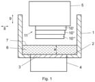
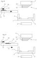
- Fig. 1 to 3 A method and a device for the layered construction of a component made of photopolymerizable material will first be described with reference to Fig. 1 to 3 described, which is basically already from the EP 2505341 A1 known device.
- the device located in air or another gas atmosphere has a trough 1, the trough bottom of which forms a material carrier 2 which is transparent or translucent at least in a partial area 3.
- This partial area 3 of the material carrier detects at least the extent of the surface that can be irradiated by the exposure unit 4, the exposure unit 4 being arranged under the material carrier 2.
- the exposure unit 4 has a light source (not shown) and a light modulator with which the intensity can be controlled by a control unit and set in a location-selective manner in order to generate an exposure field with the geometry desired for the layer currently being formed on the material carrier 2.
- a laser can also be used in the exposure unit, the light beam of which successively scans the exposure field with the desired intensity pattern via a movable mirror that is controlled by a control unit.
- a construction platform 5 is provided above the material carrier 2, which is carried by a lifting mechanism, not shown, so that it is height-adjustable above the Material carrier 2 is held in the area above the exposure unit 4.
- the building platform 5 can also be transparent or translucent.
- the squeegee is used when the construction platform is as in Fig. 1 shown in the raised state, and serves to distribute the material 6 evenly while setting a predetermined layer thickness.
- the layer thickness of the material 6 resulting from the material distribution process is defined by the distance of the lower edge of the doctor blade from the material carrier 2.
- the location-selective exposure specific to this component layer takes place in order to harden the component layer 10 ⁇ in the desired shape.
- the building platform 5 is raised again using the lifting mechanism, which means the in Fig. 3 shown condition.
- the photopolymerizable material 6 is no longer present in the exposed area.
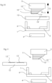
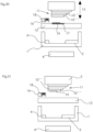
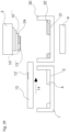
- the device therefore comprises a material removal unit 12, as in the Fig. 4 to 11 shown.
- the Fig. 4 shows the device before the formation of the component layer 10 ⁇ .
- the material removal unit 12 is positioned in its starting position next to the trough 1 and is in the direction of the arrow 14 ( Fig. 5 ) movable in horizontal direction.
- Adhering material 13 is now at least partially removed after the component layer 10 ⁇ has been formed by first moving the material removal unit 12 between the component 11 and the tub 1 with the construction platform 5 raised.
- the component layer 10 ⁇ created last and the material removal unit 12 are brought into contact by a relative movement in the direction of the arrow 15, so that the uncured amount of material 13 adhering to the underside and possibly on the side surface of the lowest component layer 10 ⁇ is at least partially applied to the material removal unit 12 is transferred so that the amount of material 13 ' reaches the material removal unit 12, as in Fig. 6 is shown.
- the amount of material 13' is transferred to the material removal unit 12, for example, by the capillary action of an absorbent material of the material removal unit 12. A relative movement then takes place in order to separate the component from the material removal unit.
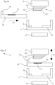
- the material removal unit 12 has an applicator 16 for a liquid, such as a solvent.
- a liquid such as a solvent.
- the liquid is applied to the surface of the material removal unit 12, so that a saturated layer 17 is created ( Fig. 13 ).
- the adhering amount of material 13 is subsequently at least partially transferred from the component layer with the aid of the layer 17 ( Fig. 15 ), so that the amount of material 13 ' reaches the material removal unit 12.
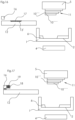
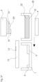
- Fig. 22 to 31 show an example of a process with which a component layer can be produced from two different photopolymerizable materials.
- a modified device is used which, in comparison to the previous examples, has a second material trough 20 with a material carrier 21, in which a second material 22 is accommodated.
- the component 11 is immersed in the second material 22 until the previously created component layer 10 touches the material carrier 2, so that a material layer is formed in the partial area 23, which is hardened ( Fig. 28 ). Since the adhering amount of material 13 of the first material 6 is previously at least partially transferred to the material removal unit 12, so that the amount of material 13 'reaches the material removal unit 12, it is avoided that material 6 mixes with the material 22 when immersed in the tub 20. Furthermore, it is avoided that the previously adhering amount of material 13 is also hardened by the last-mentioned training and distorts the geometry to be formed.
- Fig. 29 the partial layer 24 produced from the second material 22 can be seen.
- the amount of material 13" adhering to the last component layer is again at least partially transferred to the material removal unit 12, so that the amount of material 13" reaches the material removal unit 12 ( Fig. 30 and 31 ).
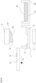
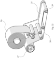
- Fig. 32 shows a preferred embodiment of the material removal unit 12.
- the material removal unit 12 comprises a movable belt 25, which is unrolled from a supply roll 26 and rolled up onto the receiver roll 27. In between, the movable belt 25 is guided around several deflection and pressure rollers, with a section of the belt 25 located between the rollers 28 and 29 forming the contact section, which is brought into contact with the component layer in order to at least partially transfer the adhering amount of material 13 to the material removal unit 12 to transfer so that the amount of material 13 ' reaches the material removal unit 12.
- the movable belt 25 can consist of an absorbent material, in particular based on cellulose.
- Fig. 33 shows an alternative design of the material removal unit 12, with which the adhering amount of material 13 is at least partially removed or sucked off pneumatically.
- the material removal unit 12 comprises a first channel 30 for a gas, which generates a negative pressure at the mouth of the channel 32 using the Venturi effect.
- Another channel 31 opens at the surface of the material removal unit 12 and generates a gas jet directed against the adhering amount of material 13.
- an overpressure is also generated on the underside of the component by generating a gas pressure via bores 33 (or other cavities) formed in the component 11 and the construction platform 5
- Adhering amount of material 13 is directed towards the channel 32.
Landscapes
- Engineering & Computer Science (AREA)
- Chemical & Material Sciences (AREA)
- Materials Engineering (AREA)
- Manufacturing & Machinery (AREA)
- Optics & Photonics (AREA)
- Mechanical Engineering (AREA)
- Physics & Mathematics (AREA)
- Ceramic Engineering (AREA)
- Civil Engineering (AREA)
- Composite Materials (AREA)
- Structural Engineering (AREA)
- Health & Medical Sciences (AREA)
- Toxicology (AREA)
Claims (14)
- Procédé pour la construction en couches d'un composant (11) en un matériau photopolymérisable, en particulier une résine avec une charge céramique ou métallique, dans lequel des couches de composant (10', 10", 10ʺ′) sont formées l'une après l'autre, l'une sur l'autre, une couche de matériau (6) du matériau photopolymérisable étant formée à chaque fois sur un support de matériau (2), et la plate-forme de construction (5) ou le composant (11) construit au moins partiellement au niveau de la plate-forme de construction (5) étant abaissé(e) dans la couche de matériau (6), de sorte qu'une couche du matériau photopolymérisable se forme entre la plate-forme de construction (5) resp. le composant (11) et le support de matériau (2), qui est durcie de manière sélective en fonction de la position, en particulier par irradiation à travers le support de matériau (2), afin d'obtenir la géométrie souhaitée de la couche de composant (10', 10", 10ʺ′), après quoi le composant (11) est soulevé avec la couche de composant (10', 10", 10ʺ′), une étape d'enlèvement de matière ayant lieu après la formation d'une couche de composant (10', 10", 10ʺ′), dans lequel, le composant (11) ayant été soulevé, du matériau photopolymérisable non-durci ou pas complètement durci qui adhère au composant (11), en particulier à la couche de composant (10', 10", 10ʺ′), est enlevé au moins partiellement au moyen d'une unité d'enlèvement de matière (12),
caractérisé en ce que
pour l'étape d'enlèvement de matière, l'unité d'enlèvement de matière (12) est amenée entre le composant soulevé (11) et le support de matériau (2). - Procédé selon la revendication 1, caractérisé en ce que l'étape d'enlèvement de matière comprend la mise en contact du matériau photopolymérisable adhérent avec un élément de contact, de préférence un élément de contact absorbant, notamment plat.
- Procédé selon la revendication 2, caractérisé en ce que l'élément de contact est conçu comme une bande mobile, la bande étant déplacée après une étape d'enlèvement de matière afin d'évacuer une section de bande contenant du matériau photopolymérisable et afin de fournir une nouvelle section de bande pour une autre étape d'enlèvement de matière.
- Procédé selon l'une des revendications 1, 2 ou 3, caractérisé en ce que l'étape d'enlèvement de matière est réalisée en au moins deux étapes, dans lequel, dans une première étape, on enlève une partie du matériau photopolymérisable adhérent, et dans une seconde étape, et éventuellement au moins une étape supplémentaire, on enlève une quantité résiduelle de matériau photopolymérisable adhérent.
- Procédé selon l'une des revendications 2, 3 ou 4, caractérisé en ce que l'élément de contact absorbant est imprégné d'un liquide ou est muni d'un liquide, de préférence un solvant, avant sa mise en contact.
- Procédé selon l'une des revendications 2 à 5, caractérisé en ce que des particules sont appliquées sur la couche de composant après l'étape d'enlèvement de matière, les particules étant de préférence transportées avec l'élément de contact vers la couche de composant et étant appliquées sur la couche de composant en mettant l'élément de contact en contact avec la couche de composant.
- Procédé selon l'une des revendications 1 à 6, caractérisé en ce que, après l'étape d'enlèvement de matière, la couche de composant est soumise à un contrôle optique à l'aide d'un appareil d'enregistrement d'images ou d'un scanner 3D.
- Procédé selon l'une des revendications 1 à 7, caractérisé en ce qu'une première couche de composant est formée à partir d'un premier matériau photopolymérisable et en ce que, après l'étape d'enlèvement de matière pour enlever du premier matériau photopolymérisable adhérent à la première couche de composant, une deuxième couche de composant est formée à partir d'un deuxième matériau photopolymérisable, qui est différent du premier matériau photopolymérisable.
- Procédé selon l'une des revendications 1 à 8, caractérisé en ce que une couche de composant avec une première géométrie est formée à partir d'un premier matériau photopolymérisable, la première géométrie laissant non-couverte au moins une zone partielle de la couche de composant formée en dernier lieu, en ce que, dans l'étape d'enlèvement de matière, on enlève du premier matériau photopolymérisable adhérent à la couche de composant et dans l'au moins une zone partielle non-couverte, et en ce que une étape de construction est ensuite réalisée avec un deuxième matériau photopolymérisable, qui est différent du premier matériau photopolymérisable, l'étape de construction comprenant le durcissement du matériau dans la zone partielle.
- Procédé selon l'une des revendications 1 à 9, caractérisé en ce que l'étape d'enlèvement de matière comprend la génération d'un flux de fluide, tel que par ex. un flux de liquide ou de gaz, au niveau du matériau photopolymérisable adhérent et non durci, qui entraîne le matériau.
- Dispositif pour la mise en oeuvre du procédé selon l'une des revendications 1 à 10, comprenant- un support de matériau (2) pour un matériau photopolymérisable, qui est au moins partiellement translucide,- une plate-forme de construction (5), qui est maintenue à une hauteur réglable au-dessus du support de matériau (2),- une unité d'irradiation (4), qui peut être commandée pour l'irradiation de manière sélective en fonction de la position d'une couche de matériau (6) formée entre la face inférieure de la plate-forme de construction (5) et le support de matériau (2), moyennant quoi une couche de composant (10', 10", 10ʺ′) peut être produite,- une unité d'enlèvement de matière (12) pour l'enlèvement au moins partiel de matériau photopolymérisable non durci adhérant au composant (11) après le soulèvement de celui-ci, en particulier à la couche de composant (10', 10", 10ʺ′), caractérisé en ce que l'unité d'enlèvement de matière (12) est disposée de manière mobile, pour être amenée entre le composant soulevé (11) et le support de matériau (2) pour l'étape d'enlèvement de matière.
- Dispositif selon la revendication 11, caractérisé en ce que l'unité d'enlèvement de matière comprend un élément de contact, de préférence un élément de contact absorbant, notamment plat, qui est conçu pour sa mise en contact avec le matériau photopolymérisable adhérent.
- Dispositif selon la revendication 11 ou 12, caractérisé en ce que l'élément de contact est conçu comme une bande mobile.
- Dispositif selon la revendication 12 ou 13, caractérisé en ce que l'unité d'enlèvement de matière comporte un applicateur pour appliquer un liquide, de préférence un solvant, ou des particules sur l'élément de contact.
Priority Applications (2)
| Application Number | Priority Date | Filing Date | Title |
|---|---|---|---|
| EP20020586.2A EP4008523B1 (fr) | 2020-12-03 | 2020-12-03 | Procédé et dispositif de construction en couches d'un composant en matière photopolymerisable |
| US17/538,772 US20220176626A1 (en) | 2020-12-03 | 2021-11-30 | Method and device for building up a component in layers from photopolymerizable material |
Applications Claiming Priority (1)
| Application Number | Priority Date | Filing Date | Title |
|---|---|---|---|
| EP20020586.2A EP4008523B1 (fr) | 2020-12-03 | 2020-12-03 | Procédé et dispositif de construction en couches d'un composant en matière photopolymerisable |
Publications (3)
| Publication Number | Publication Date |
|---|---|
| EP4008523A1 EP4008523A1 (fr) | 2022-06-08 |
| EP4008523B1 true EP4008523B1 (fr) | 2023-11-29 |
| EP4008523C0 EP4008523C0 (fr) | 2023-11-29 |
Family
ID=73726532
Family Applications (1)
| Application Number | Title | Priority Date | Filing Date |
|---|---|---|---|
| EP20020586.2A Active EP4008523B1 (fr) | 2020-12-03 | 2020-12-03 | Procédé et dispositif de construction en couches d'un composant en matière photopolymerisable |
Country Status (2)
| Country | Link |
|---|---|
| US (1) | US20220176626A1 (fr) |
| EP (1) | EP4008523B1 (fr) |
Families Citing this family (2)
| Publication number | Priority date | Publication date | Assignee | Title |
|---|---|---|---|---|
| US20240033993A1 (en) * | 2022-07-28 | 2024-02-01 | General Electric Company | Systems and methods for additive manufacturing |
| CN115816826B (zh) * | 2022-09-30 | 2025-07-01 | 上海普利生三维科技有限公司 | 混合多材料三维打印方法及系统 |
Citations (1)
| Publication number | Priority date | Publication date | Assignee | Title |
|---|---|---|---|---|
| EP3621186B1 (fr) * | 2018-09-05 | 2021-03-17 | VAF GmbH | Dispositif de nettoyage et procédé de nettoyage d'un corps revêtu trempé |
Family Cites Families (9)
| Publication number | Priority date | Publication date | Assignee | Title |
|---|---|---|---|---|
| WO2010045950A1 (fr) | 2008-10-20 | 2010-04-29 | Ivoclar Vivadent Ag | Dispositif et procédé de traitement d’un matériau photopolymérisable permettant la réalisation par couches de corps moulés |
| ES2934103T3 (es) * | 2011-01-31 | 2023-02-16 | Global Filtration Systems Dba Gulf Filtration Systems Inc | Aparato para fabricar objetos tridimensionales a partir de múltiples materiales solidificables |
| EP2505341B1 (fr) | 2011-03-29 | 2013-05-08 | Ivoclar Vivadent AG | Procédé de fabrication par couches d'un objet en matériau photopolymérisable hautement visqueux |
| TW201522017A (zh) * | 2013-12-13 | 2015-06-16 | 三緯國際立體列印科技股份有限公司 | 立體列印裝置 |
| US11141919B2 (en) * | 2015-12-09 | 2021-10-12 | Holo, Inc. | Multi-material stereolithographic three dimensional printing |
| US11027487B2 (en) * | 2018-03-27 | 2021-06-08 | Carbon, Inc. | Functional surface coating methods for additively manufactured products |
| WO2019204095A1 (fr) * | 2018-04-20 | 2019-10-24 | Carbon, Inc. | Méthodes de revêtement de surface liée pour produits fabriqués par fabrication additive |
| KR102197597B1 (ko) | 2018-12-27 | 2021-01-05 | 한국재료연구원 | 3차원 프린팅 구조체 세척장치 및 이를 이용한 3차원 프린팅 구조체 세척방법 |
| EP3969245A4 (fr) * | 2019-05-17 | 2023-01-25 | Holo, Inc. | Procédés et systèmes d'impression tridimensionnelle par stéréolithographie |
-
2020
- 2020-12-03 EP EP20020586.2A patent/EP4008523B1/fr active Active
-
2021
- 2021-11-30 US US17/538,772 patent/US20220176626A1/en not_active Abandoned
Patent Citations (1)
| Publication number | Priority date | Publication date | Assignee | Title |
|---|---|---|---|---|
| EP3621186B1 (fr) * | 2018-09-05 | 2021-03-17 | VAF GmbH | Dispositif de nettoyage et procédé de nettoyage d'un corps revêtu trempé |
Also Published As
| Publication number | Publication date |
|---|---|
| US20220176626A1 (en) | 2022-06-09 |
| EP4008523C0 (fr) | 2023-11-29 |
| EP4008523A1 (fr) | 2022-06-08 |
Similar Documents
| Publication | Publication Date | Title |
|---|---|---|
| EP2855119B1 (fr) | Procédé destiné à la création d'un objet tridimensionnel | |
| EP2864108B1 (fr) | Dispositif et procédé de fabrication par couches d'un objet tridimensionnel | |
| DE69623213T2 (de) | Verfahren und Anlage zum Düsebeschichten | |
| DE19957370C2 (de) | Verfahren und Vorrichtung zum Beschichten eines Substrates | |
| EP3277481B1 (fr) | Procédé et dispositif de fabrication additive d'un corps | |
| DE69820905T2 (de) | Vorrichtung zum aufbringen eines materials auf einem substrat | |
| DE60012667T2 (de) | Vorrichtung zur Herstellung eines dreidimensionalen laminierten Gegenstandes aus einer lichthärtenden Flüssigkeit | |
| DE4134265C2 (de) | Vorrichtung und Verfahren zur Herstellung eines dreidimensionalen Objekts mittels Stereographie | |
| DE69431311T2 (de) | Vorrichtung zur Modellerzeugung durch Folienlaminierung | |
| EP3277482B1 (fr) | Procédé et dispositif de fabrication additive d'un corps | |
| EP1144146B1 (fr) | Dispositif de fusion selective au laser pour la fabrication d'un corps moule | |
| EP0897796B1 (fr) | Procédé de fabrication d'un gabarit de sérigraphie et dispositif à cet effet | |
| EP0739704A1 (fr) | Dispositif pour produire un objet par stéréolithographie | |
| EP4008523B1 (fr) | Procédé et dispositif de construction en couches d'un composant en matière photopolymerisable | |
| EP4096898A1 (fr) | Imprimante 3d pour la fabrication additive d'une pièce et procédé d'impression | |
| DE2833377A1 (de) | Verfahren zum aufbringen von hochviskosem beschichtungsmaterial auf ein metallband sowie vorrichtung zur durchfuehrung dieses verfahrens | |
| DE3012988A1 (de) | Vorrichtung und verfahren zur herstellung eines druckplattenrohlings | |
| EP1523413B1 (fr) | Procede et dispositif pour la production d'un timbre | |
| WO2018146287A1 (fr) | Procédé et dispositif de fabrication d'un objet moulé tridimensionnel par apport de matière par couches | |
| WO1996014203A1 (fr) | Procede et dispositif pour la production d'un objet a trois dimensions | |
| DE10225541A1 (de) | Verfahren und Vorrichtung zum Herstellen eines hülsenförmigen Gummituchs | |
| EP0733951B1 (fr) | Procédé et appareil pour la fabrication d'un écran sérigraphique | |
| DE10159084A1 (de) | Druckform für den Hoch- oder Tiefdruck sowie Verfahren zu ihrer Herstellung | |
| DE102019007480A1 (de) | Anordnung und Verfahren zum Erzeugen einer Schicht eines partikelförmigen Baumaterials in einem 3D-Drucker | |
| DE102024101731B3 (de) | Anordnung und Verfahren für den Bad-basierten 3D-Druck |
Legal Events
| Date | Code | Title | Description |
|---|---|---|---|
| PUAI | Public reference made under article 153(3) epc to a published international application that has entered the european phase |
Free format text: ORIGINAL CODE: 0009012 |
|
| STAA | Information on the status of an ep patent application or granted ep patent |
Free format text: STATUS: THE APPLICATION HAS BEEN PUBLISHED |
|
| AK | Designated contracting states |
Kind code of ref document: A1 Designated state(s): AL AT BE BG CH CY CZ DE DK EE ES FI FR GB GR HR HU IE IS IT LI LT LU LV MC MK MT NL NO PL PT RO RS SE SI SK SM TR |
|
| STAA | Information on the status of an ep patent application or granted ep patent |
Free format text: STATUS: REQUEST FOR EXAMINATION WAS MADE |
|
| 17P | Request for examination filed |
Effective date: 20221201 |
|
| RBV | Designated contracting states (corrected) |
Designated state(s): AL AT BE BG CH CY CZ DE DK EE ES FI FR GB GR HR HU IE IS IT LI LT LU LV MC MK MT NL NO PL PT RO RS SE SI SK SM TR |
|
| TPAC | Observations filed by third parties |
Free format text: ORIGINAL CODE: EPIDOSNTIPA |
|
| RIC1 | Information provided on ipc code assigned before grant |
Ipc: B22F 7/08 20060101ALI20230608BHEP Ipc: B29C 64/194 20170101ALI20230608BHEP Ipc: B29C 64/236 20170101ALI20230608BHEP Ipc: B29C 64/241 20170101ALI20230608BHEP Ipc: B29C 64/321 20170101ALI20230608BHEP Ipc: B29C 64/35 20170101ALI20230608BHEP Ipc: B33Y 10/00 20150101ALI20230608BHEP Ipc: B33Y 30/00 20150101ALI20230608BHEP Ipc: B33Y 40/00 20200101ALI20230608BHEP Ipc: B22F 10/00 20210101ALI20230608BHEP Ipc: B22F 12/00 20210101ALI20230608BHEP Ipc: B33Y 70/10 20200101ALI20230608BHEP Ipc: B08B 1/00 20060101ALI20230608BHEP Ipc: B29C 64/124 20170101AFI20230608BHEP |
|
| GRAP | Despatch of communication of intention to grant a patent |
Free format text: ORIGINAL CODE: EPIDOSNIGR1 |
|
| STAA | Information on the status of an ep patent application or granted ep patent |
Free format text: STATUS: GRANT OF PATENT IS INTENDED |
|
| INTG | Intention to grant announced |
Effective date: 20230717 |
|
| GRAS | Grant fee paid |
Free format text: ORIGINAL CODE: EPIDOSNIGR3 |
|
| GRAA | (expected) grant |
Free format text: ORIGINAL CODE: 0009210 |
|
| STAA | Information on the status of an ep patent application or granted ep patent |
Free format text: STATUS: THE PATENT HAS BEEN GRANTED |
|
| AK | Designated contracting states |
Kind code of ref document: B1 Designated state(s): AL AT BE BG CH CY CZ DE DK EE ES FI FR GB GR HR HU IE IS IT LI LT LU LV MC MK MT NL NO PL PT RO RS SE SI SK SM TR |
|
| REG | Reference to a national code |
Ref country code: GB Ref legal event code: FG4D Free format text: NOT ENGLISH |
|
| REG | Reference to a national code |
Ref country code: CH Ref legal event code: EP |
|
| REG | Reference to a national code |
Ref country code: DE Ref legal event code: R096 Ref document number: 502020006164 Country of ref document: DE |
|
| REG | Reference to a national code |
Ref country code: IE Ref legal event code: FG4D Free format text: LANGUAGE OF EP DOCUMENT: GERMAN |
|
| U01 | Request for unitary effect filed |
Effective date: 20231206 |
|
| U07 | Unitary effect registered |
Designated state(s): AT BE BG DE DK EE FI FR IT LT LU LV MT NL PT SE SI Effective date: 20231212 |
|
| U20 | Renewal fee for the european patent with unitary effect paid |
Year of fee payment: 4 Effective date: 20231207 |
|
| PG25 | Lapsed in a contracting state [announced via postgrant information from national office to epo] |
Ref country code: GR Free format text: LAPSE BECAUSE OF FAILURE TO SUBMIT A TRANSLATION OF THE DESCRIPTION OR TO PAY THE FEE WITHIN THE PRESCRIBED TIME-LIMIT Effective date: 20240301 |
|
| PG25 | Lapsed in a contracting state [announced via postgrant information from national office to epo] |
Ref country code: IS Free format text: LAPSE BECAUSE OF FAILURE TO SUBMIT A TRANSLATION OF THE DESCRIPTION OR TO PAY THE FEE WITHIN THE PRESCRIBED TIME-LIMIT Effective date: 20240329 |
|
| PG25 | Lapsed in a contracting state [announced via postgrant information from national office to epo] |
Ref country code: ES Free format text: LAPSE BECAUSE OF FAILURE TO SUBMIT A TRANSLATION OF THE DESCRIPTION OR TO PAY THE FEE WITHIN THE PRESCRIBED TIME-LIMIT Effective date: 20231129 |
|
| PG25 | Lapsed in a contracting state [announced via postgrant information from national office to epo] |
Ref country code: IS Free format text: LAPSE BECAUSE OF FAILURE TO SUBMIT A TRANSLATION OF THE DESCRIPTION OR TO PAY THE FEE WITHIN THE PRESCRIBED TIME-LIMIT Effective date: 20240329 Ref country code: GR Free format text: LAPSE BECAUSE OF FAILURE TO SUBMIT A TRANSLATION OF THE DESCRIPTION OR TO PAY THE FEE WITHIN THE PRESCRIBED TIME-LIMIT Effective date: 20240301 Ref country code: ES Free format text: LAPSE BECAUSE OF FAILURE TO SUBMIT A TRANSLATION OF THE DESCRIPTION OR TO PAY THE FEE WITHIN THE PRESCRIBED TIME-LIMIT Effective date: 20231129 |
|
| PG25 | Lapsed in a contracting state [announced via postgrant information from national office to epo] |
Ref country code: RS Free format text: LAPSE BECAUSE OF FAILURE TO SUBMIT A TRANSLATION OF THE DESCRIPTION OR TO PAY THE FEE WITHIN THE PRESCRIBED TIME-LIMIT Effective date: 20231129 Ref country code: PL Free format text: LAPSE BECAUSE OF FAILURE TO SUBMIT A TRANSLATION OF THE DESCRIPTION OR TO PAY THE FEE WITHIN THE PRESCRIBED TIME-LIMIT Effective date: 20231129 Ref country code: NO Free format text: LAPSE BECAUSE OF FAILURE TO SUBMIT A TRANSLATION OF THE DESCRIPTION OR TO PAY THE FEE WITHIN THE PRESCRIBED TIME-LIMIT Effective date: 20240229 Ref country code: HR Free format text: LAPSE BECAUSE OF FAILURE TO SUBMIT A TRANSLATION OF THE DESCRIPTION OR TO PAY THE FEE WITHIN THE PRESCRIBED TIME-LIMIT Effective date: 20231129 |
|
| PG25 | Lapsed in a contracting state [announced via postgrant information from national office to epo] |
Ref country code: CZ Free format text: LAPSE BECAUSE OF FAILURE TO SUBMIT A TRANSLATION OF THE DESCRIPTION OR TO PAY THE FEE WITHIN THE PRESCRIBED TIME-LIMIT Effective date: 20231129 |
|
| PG25 | Lapsed in a contracting state [announced via postgrant information from national office to epo] |
Ref country code: SK Free format text: LAPSE BECAUSE OF FAILURE TO SUBMIT A TRANSLATION OF THE DESCRIPTION OR TO PAY THE FEE WITHIN THE PRESCRIBED TIME-LIMIT Effective date: 20231129 |
|
| PG25 | Lapsed in a contracting state [announced via postgrant information from national office to epo] |
Ref country code: SM Free format text: LAPSE BECAUSE OF FAILURE TO SUBMIT A TRANSLATION OF THE DESCRIPTION OR TO PAY THE FEE WITHIN THE PRESCRIBED TIME-LIMIT Effective date: 20231129 Ref country code: SK Free format text: LAPSE BECAUSE OF FAILURE TO SUBMIT A TRANSLATION OF THE DESCRIPTION OR TO PAY THE FEE WITHIN THE PRESCRIBED TIME-LIMIT Effective date: 20231129 Ref country code: RO Free format text: LAPSE BECAUSE OF FAILURE TO SUBMIT A TRANSLATION OF THE DESCRIPTION OR TO PAY THE FEE WITHIN THE PRESCRIBED TIME-LIMIT Effective date: 20231129 Ref country code: CZ Free format text: LAPSE BECAUSE OF FAILURE TO SUBMIT A TRANSLATION OF THE DESCRIPTION OR TO PAY THE FEE WITHIN THE PRESCRIBED TIME-LIMIT Effective date: 20231129 |
|
| REG | Reference to a national code |
Ref country code: CH Ref legal event code: PL |
|
| U1N | Appointed representative for the unitary patent procedure changed after the registration of the unitary effect |
Representative=s name: SONN PATENTANWAELTE GMBH & CO KG; AT |
|
| PG25 | Lapsed in a contracting state [announced via postgrant information from national office to epo] |
Ref country code: MC Free format text: LAPSE BECAUSE OF FAILURE TO SUBMIT A TRANSLATION OF THE DESCRIPTION OR TO PAY THE FEE WITHIN THE PRESCRIBED TIME-LIMIT Effective date: 20231129 |
|
| PG25 | Lapsed in a contracting state [announced via postgrant information from national office to epo] |
Ref country code: MC Free format text: LAPSE BECAUSE OF FAILURE TO SUBMIT A TRANSLATION OF THE DESCRIPTION OR TO PAY THE FEE WITHIN THE PRESCRIBED TIME-LIMIT Effective date: 20231129 |
|
| REG | Reference to a national code |
Ref country code: DE Ref legal event code: R097 Ref document number: 502020006164 Country of ref document: DE |
|
| PLBE | No opposition filed within time limit |
Free format text: ORIGINAL CODE: 0009261 |
|
| STAA | Information on the status of an ep patent application or granted ep patent |
Free format text: STATUS: NO OPPOSITION FILED WITHIN TIME LIMIT |
|
| REG | Reference to a national code |
Ref country code: IE Ref legal event code: MM4A |
|
| PG25 | Lapsed in a contracting state [announced via postgrant information from national office to epo] |
Ref country code: IE Free format text: LAPSE BECAUSE OF NON-PAYMENT OF DUE FEES Effective date: 20231203 |
|
| PG25 | Lapsed in a contracting state [announced via postgrant information from national office to epo] |
Ref country code: CH Free format text: LAPSE BECAUSE OF NON-PAYMENT OF DUE FEES Effective date: 20231231 |
|
| PG25 | Lapsed in a contracting state [announced via postgrant information from national office to epo] |
Ref country code: IE Free format text: LAPSE BECAUSE OF NON-PAYMENT OF DUE FEES Effective date: 20231203 Ref country code: CH Free format text: LAPSE BECAUSE OF NON-PAYMENT OF DUE FEES Effective date: 20231231 |
|
| 26N | No opposition filed |
Effective date: 20240830 |
|
| U20 | Renewal fee for the european patent with unitary effect paid |
Year of fee payment: 5 Effective date: 20241107 |
|
| PG25 | Lapsed in a contracting state [announced via postgrant information from national office to epo] |
Ref country code: CY Free format text: LAPSE BECAUSE OF FAILURE TO SUBMIT A TRANSLATION OF THE DESCRIPTION OR TO PAY THE FEE WITHIN THE PRESCRIBED TIME-LIMIT; INVALID AB INITIO Effective date: 20201203 |
|
| PG25 | Lapsed in a contracting state [announced via postgrant information from national office to epo] |
Ref country code: HU Free format text: LAPSE BECAUSE OF FAILURE TO SUBMIT A TRANSLATION OF THE DESCRIPTION OR TO PAY THE FEE WITHIN THE PRESCRIBED TIME-LIMIT; INVALID AB INITIO Effective date: 20201203 |
|
| GBPC | Gb: european patent ceased through non-payment of renewal fee |
Effective date: 20241203 |
|
| PG25 | Lapsed in a contracting state [announced via postgrant information from national office to epo] |
Ref country code: GB Free format text: LAPSE BECAUSE OF NON-PAYMENT OF DUE FEES Effective date: 20241203 |
|
| U20 | Renewal fee for the european patent with unitary effect paid |
Year of fee payment: 6 Effective date: 20251104 |
|
| PG25 | Lapsed in a contracting state [announced via postgrant information from national office to epo] |
Ref country code: TR Free format text: LAPSE BECAUSE OF FAILURE TO SUBMIT A TRANSLATION OF THE DESCRIPTION OR TO PAY THE FEE WITHIN THE PRESCRIBED TIME-LIMIT Effective date: 20231129 |