EP4008875A1 - Store vénitien et procédé de modification d'un store vénitien - Google Patents
Store vénitien et procédé de modification d'un store vénitien Download PDFInfo
- Publication number
- EP4008875A1 EP4008875A1 EP21211922.6A EP21211922A EP4008875A1 EP 4008875 A1 EP4008875 A1 EP 4008875A1 EP 21211922 A EP21211922 A EP 21211922A EP 4008875 A1 EP4008875 A1 EP 4008875A1
- Authority
- EP
- European Patent Office
- Prior art keywords
- venetian blind
- slats
- external venetian
- traction
- coupled
- Prior art date
- Legal status (The legal status is an assumption and is not a legal conclusion. Google has not performed a legal analysis and makes no representation as to the accuracy of the status listed.)
- Withdrawn
Links
- 238000000034 method Methods 0.000 title claims abstract description 16
- 230000008878 coupling Effects 0.000 claims description 68
- 238000010168 coupling process Methods 0.000 claims description 68
- 238000005859 coupling reaction Methods 0.000 claims description 68
- 238000004804 winding Methods 0.000 claims description 13
- 238000004904 shortening Methods 0.000 claims description 5
- 230000008672 reprogramming Effects 0.000 claims description 4
- 238000004519 manufacturing process Methods 0.000 claims description 3
- 230000001066 destructive effect Effects 0.000 claims 1
- 230000007246 mechanism Effects 0.000 description 44
- 238000012986 modification Methods 0.000 description 6
- 239000004020 conductor Substances 0.000 description 5
- 230000008901 benefit Effects 0.000 description 4
- 230000008859 change Effects 0.000 description 4
- 230000004048 modification Effects 0.000 description 4
- 238000009434 installation Methods 0.000 description 3
- 241000446313 Lamella Species 0.000 description 1
- 230000005540 biological transmission Effects 0.000 description 1
- 238000006243 chemical reaction Methods 0.000 description 1
- 238000011161 development Methods 0.000 description 1
- 230000018109 developmental process Effects 0.000 description 1
- 230000000694 effects Effects 0.000 description 1
- 239000000463 material Substances 0.000 description 1
- 238000012544 monitoring process Methods 0.000 description 1
- 230000037072 sun protection Effects 0.000 description 1
Images



Classifications
-
- E—FIXED CONSTRUCTIONS
- E06—DOORS, WINDOWS, SHUTTERS, OR ROLLER BLINDS IN GENERAL; LADDERS
- E06B—FIXED OR MOVABLE CLOSURES FOR OPENINGS IN BUILDINGS, VEHICLES, FENCES OR LIKE ENCLOSURES IN GENERAL, e.g. DOORS, WINDOWS, BLINDS, GATES
- E06B9/00—Screening or protective devices for wall or similar openings, with or without operating or securing mechanisms; Closures of similar construction
- E06B9/24—Screens or other constructions affording protection against light, especially against sunshine; Similar screens for privacy or appearance; Slat blinds
- E06B9/26—Lamellar or like blinds, e.g. venetian blinds
- E06B9/28—Lamellar or like blinds, e.g. venetian blinds with horizontal lamellae, e.g. non-liftable
- E06B9/30—Lamellar or like blinds, e.g. venetian blinds with horizontal lamellae, e.g. non-liftable liftable
- E06B9/303—Lamellar or like blinds, e.g. venetian blinds with horizontal lamellae, e.g. non-liftable liftable with ladder-tape
-
- E—FIXED CONSTRUCTIONS
- E06—DOORS, WINDOWS, SHUTTERS, OR ROLLER BLINDS IN GENERAL; LADDERS
- E06B—FIXED OR MOVABLE CLOSURES FOR OPENINGS IN BUILDINGS, VEHICLES, FENCES OR LIKE ENCLOSURES IN GENERAL, e.g. DOORS, WINDOWS, BLINDS, GATES
- E06B9/00—Screening or protective devices for wall or similar openings, with or without operating or securing mechanisms; Closures of similar construction
- E06B9/24—Screens or other constructions affording protection against light, especially against sunshine; Similar screens for privacy or appearance; Slat blinds
- E06B9/26—Lamellar or like blinds, e.g. venetian blinds
- E06B9/38—Other details
-
- E—FIXED CONSTRUCTIONS
- E06—DOORS, WINDOWS, SHUTTERS, OR ROLLER BLINDS IN GENERAL; LADDERS
- E06B—FIXED OR MOVABLE CLOSURES FOR OPENINGS IN BUILDINGS, VEHICLES, FENCES OR LIKE ENCLOSURES IN GENERAL, e.g. DOORS, WINDOWS, BLINDS, GATES
- E06B9/00—Screening or protective devices for wall or similar openings, with or without operating or securing mechanisms; Closures of similar construction
- E06B9/24—Screens or other constructions affording protection against light, especially against sunshine; Similar screens for privacy or appearance; Slat blinds
- E06B9/26—Lamellar or like blinds, e.g. venetian blinds
- E06B9/38—Other details
- E06B9/388—Details of bottom or upper slats or their attachment
Definitions
- the invention relates to a method for modifying, in particular for reducing the maximum vertical length, of an external venetian blind which has slats parallel to one another and which can be selectively converted into a retracted state or an extended state.
- the invention also relates to an external venetian blind that has slats that are parallel to one another and that can be selectively converted into a retracted state or an extended state.
- An external venetian blind is a sun protection device to be fitted on the outside of a window or door of a building with horizontally aligned, parallel slats, which are usually held by flexible conductors, which ensure the spacing of the slats when the external venetian blind is extended and allow the angle of the slats to be adjusted.
- a lower rail which is usually connected to a drive device in a hanging manner by means of two traction means.
- the object is achieved by a method that is characterized in that several of the slats are coupled to one another in such a way that they have the same distance from one another when the external venetian blind is in the extended state as when it is in the retracted state.
- a further object of the present invention is to specify a venetian blind whose size can be adapted to the respective application situation.
- an external venetian blind which is characterized by a coupling device by means of which several of the slats can be coupled in such a way that they have the same distance from one another when the external venetian blind is in the extended state as when it is in the retracted state.
- the invention makes it possible in particular to convert an already manufactured and functional external venetian blind in a simple manner in order to be able to subsequently individually adapt it to the respective situation at the installation site, in particular to the height of the respective building opening, for example a window height or a door height.
- the installation of the coupling device can in particular also be carried out subsequently in an already existing and functional external venetian blind.
- the invention makes it possible, in particular, to be able to adapt the size of an external venetian blind to the respective application situation without having to permanently damage or dismantle parts of the external venetian blind.
- the conversion can advantageously also be reversed again by removing the coupling device again.
- it is not fundamentally impossible to permanently change the slats to be coupled for example by introducing additional bores and/or by screwing in screws, for the purpose of coupling.
- the extended state is that state in which the external venetian blind has the maximum vertical length that can be achieved using a manual or electric drive device.
- the retracted state is the state in which the external venetian blind is fully retracted and all slats are at their minimum distance from one another.
- the vertical length of the external venetian blind is reduced when fully extended, because the slats that are coupled together (in contrast to the non- coupled slats) maintain their closely spaced spacing.
- the coupling of slats prevents the ladder from being able to unfold completely.
- the external venetian blind would not be able to be extended at all if all the slats, including any bottom rail that might be present, were coupled to one another. If you were to couple 10% of the existing slats in a venetian blind (preferably the top ones), the maximum vertical length of the venetian blind that can be achieved by means of the drive device when fully extended would correspondingly be reduced by about 10%.
- a venetian blind according to the invention can be produced according to an independent inventive idea, in particular in that several slats, in particular several of the uppermost slats, of an external venetian blind are coupled so that they have the same distance from one another when the external venetian blind is in the extended state as when it is retracted Condition.
- the external venetian blind to be modified can in particular be one of many external venetian blinds that are pre-produced in the same way or at least in the same size.
- the invention has the further particular advantage that the slat angle can be adjusted in an unchanged manner.
- the slat angle changes in the Way that the vertical tethers of each ladder perform a vertical movement relative to each other (in particular: one tether up the other down).
- This relative vertical movement of the vertical retaining cables causes both a rotary movement of the entire block of slats coupled to one another and a rotary movement of each of the slats that are not coupled, in each case about their direction of longitudinal extension.
- the block of mutually coupled slats advantageously does not or only insignificantly impede the changing of the slat angle of the remaining, non-coupled slats in such an embodiment.
- the coupling device is preferably designed in such a way that it can be used independently of the number of slats to be coupled. The more slats that are coupled, the shorter the maximum vertical extension length of the external venetian blind.
- the uppermost slats of the external venetian blind are preferably coupled to one another. This has the very particular advantage that when the external venetian blind is extended, they remain completely or partially outside of the field of vision, in particular remain in a drive device housing, and are therefore not visible or at least not visually noticeable.
- the maximum output length of at least one traction device that connects a lower rail of the external venetian blind to a drive device, in particular an electric drive device is reduced.
- the maximum output length is preferably reduced in such a way that when fully extended (i.e. at the maximum output length of the traction mechanism), no more slats are lying on top of each other apart from the coupled slats and/or the distance between the lower rail and the directly adjacent slat corresponds to the distance between the other slats that are directly adjacent to one another.
- the slats are held by flexible conductors, when fully extended, adjacent, non-coupled slats are at the distance from one another that is predetermined by the distance between adjacent transverse cables.
- the maximum output length of the traction mechanism can be achieved by changing, in particular reprogramming and/or teaching, an end position setting of a control device that controls the drive device.
- the teaching takes place automatically after the slats have been coupled.
- a control device operates the drive motor for extending the external venetian blind and, for example, using a Sensor signal or based on a change in the electrical power requirement of the drive motor detects when the maximum output length has been reached.
- the maximum output length can be recognized by the control device in that all non-coupled slats are carried by the ladders and no longer rest on the lower rail when the maximum output length is reached, so that their weight no longer depends on the traction means driven by the drive motor .
- This state can be detected, for example, by a change in the electrical power requirement of the drive motor, in particular by measuring the electrical current intensity.
- At least one sensor can be present, by means of which it is possible to detect when the maximum extension length has been reached.
- it can be a sensor that detects the tensile force acting on the traction device or traction devices.
- the control device can also automatically detect the upper end stop, for example by monitoring the change in the electrical power requirement of the drive motor or, for example, by means of a sensor.
- the maximum output length of the traction device it is also possible, for example, for the maximum output length of the traction device to be reduced by shortening the traction device. As an alternative or in addition, it is also possible to reduce the maximum output length of the traction means by fixing the lower rail at a different point on the traction means.
- the maximum output length of the traction device from the drive device to the bottom rail and/or the maximum distance between the bottom rail and the drive device in the vertical plane of the traction device are adjusted by means of a traction device coupling device that connects the traction device to the bottom rail.
- the traction mechanism coupling device can be arranged in particular in a cavity of the bottom rail.
- the cavity may be formed between a base portion and a lid portion of the sub-bills.
- the bottom rail has a base part that is curved perpendicularly to its direction of longitudinal extent and a cover part that is curved perpendicularly to its direction of longitudinal extent, between which the cavity is formed.
- the cover part can have the same shape and/or be made of the same material as the slats of the external venetian blind.
- the lower rail can be fixed at different points of the traction means by means of the traction mechanism coupling device, in particular steplessly. This makes it possible to easily set the maximum output length of the traction device from the drive device to the bottom rail and/or the maximum distance between the bottom rail and the drive device in the vertical plane of the traction device.
- the traction mechanism is or can be secured in a frictionally and/or positively locking manner by means of the traction mechanism coupling device.
- the traction mechanism coupling device can be designed in such a way that the traction mechanism can be clamped within the traction mechanism coupling device in order to define the setting that has been made.
- the traction means can be locked within the traction means coupling device by a form-fitting connection, for example by a mandrel that engages in the traction means, in particular a pointed mandrel, or by several mandrels, in particular pointed mandrels, that engage in the traction means, in order to Maintain the setting and set the traction mechanism.
- the traction mechanism coupling device can optionally, in particular without tools and/or non-destructively, switch between a release setting in which the maximum output length and/or the maximum distance between the bottom rail and the drive device can be adjusted and a fixed setting in which the maximum output length and /or the maximum distance between the lower rail and the drive device is fixed, can be switched.
- the traction mechanism coupling device can, for example, be designed in such a way that switching can be carried out by actuating a switching element, for example by throwing a lever or by inserting a clamping element or turning a cam.
- the venetian blind according to the invention can advantageously be designed as a front-mounted venetian blind or as a facade venetian blind or as a top-mounted venetian blind.
- the external venetian blind is preferably designed to be fastened to or in an outer wall of a building, in particular in a window or door niche.
- the drive device of the external venetian blind preferably has at least one electric drive motor, which drives a winding shaft directly or indirectly.
- a transmission can be connected downstream of the drive motor.
- the coupling device is designed so that it can be operated without tools.
- the coupling device can be designed in such a way that the coupling can be released again without tools and/or non-destructively.
- the two coupling devices are used to couple the slats.
- the two coupling devices can be attached in the area of the ends of the slats to be coupled. In this way, a secure coupling is achieved, with the coupling devices nevertheless being easy to attach.
- the coupling device can be designed, for example, as a clip or as a spring clip.
- the coupling device can be designed as a retaining strap, which is placed tightly around the slats to be coupled and whose ends are connected to one another, for example by means of a Velcro connection.
- the coupling device can in particular also be designed as an elastic ring, which is pushed laterally onto the block of slats to be coupled and holds the slats enclosed by it together.
- figure 1 shows a first exemplary embodiment of a fully extended external venetian blind in a top view with a view into the drive device housing 5 of a drive device 1 of the external venetian blind before a modification according to the invention.
- the external venetian blind has a drive device 1 with a drive motor 2 which drives two winding shafts 3 for winding up traction means 4 .
- the drive device 1 also has a drive device housing 5 in which the drive motor 2 and the winding shafts 3 and a control device 13 are arranged.
- the drive motor 2 can be designed as a geared motor.
- the traction means 4 are designed as belts (alternatively as cables) and are connected to a bottom rail 8 by means of traction means coupling devices 12 .
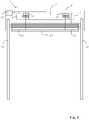
- the bottom rail 8 is pulled up into the drive device housing 5 of the drive device 1, which in figure 2 is shown.
- the lower rail 8 has a base part 15 which can be closed with a cover part 16 .
- the cover part 16 has an opening 7 for the traction mechanism 4 .
- the external venetian blind has several slats 6 .
- the slats 6 each have openings 7 through which the traction means 4 run to the bottom rail 8 .
- the slats 6 are held in the extended state of the external venetian blind by two flexible conductors 9 formed from ropes, which ensure the spacing of the slats 6 in the illustrated extended state of the external venetian blind and allow the slat angle to be adjusted.
- the ladders 9 each have two vertically running tethers 10 and between the tethers 10 transverse cross ropes 11, which in the Figures 1 to 3 are not visible because they are perpendicular to the plane of the drawing.
- the slats 6 lie on the transverse cables 11 in the illustrated extended state of the external venetian blind.
- the slats 6 are laterally guided in guide rails 14 alternately on the left and right at the ends.
- the vertically extending tethers 10 of the ladder 9 are also coupled to the drive device 1, which in the Figures 1 to 3 only schematically illustrated.
- the retaining cables 10 can each be coupled to a hollow shaft 15 which can be rotated by means of the drive motor 2 and through which the winding shafts 3 run.
- the slat angle is changed in such a way that the vertical tethers 10 of each ladder 9 perform a vertical movement relative to one another (one tether up and the other down).
- This relative vertical movement of the vertical tethers 10 causes a rotary movement of each of the slats 6 about their longitudinal extension direction.
- the drive device 1 has a control device 13, which controls the drive motor 2 and, if necessary, a switching coupling with regard to the retraction and extension of the external venetian blind and with regard to the setting of the slat angle.
- the control device 13 receives setting specifications, for example from a user via a radio remote control.
- FIG 3 shows the embodiment of the external venetian blind modified according to the invention.
- the modified external venetian blind has two coupling devices 18, by means of which several of the slats 6, namely the top four Slats 6 are coupled in such a way that they have the same distance from one another in the (shown) extended state of the external venetian blind as in the retracted state. It goes without saying that, depending on the desired total vertical length of the external venetian blind, any other number of slats 6, preferably the topmost slats 6, can be coupled.
- the top four slats 6 Due to the coupling of the top four slats 6, they remain in their retracted position (preferably within the drive device housing 5) when the traction means 4 are unwound, while the other slats 6 move downwards in the usual way until the external venetian blind (in the changed vertical length) is completely closed is extended.
- the maximum output length of the traction means 4 namely preferably the output length at which the lower rail 8 is at the same distance from the immediately adjacent slat 6 as all pairs of immediately adjacent slats 6 are to one another, can be changed, for example by changing, in particular reprogramming and/or teaching, the end position adjustment stored in the control device 13 takes place.
- the maximum output length of the traction means 4 it is also possible, for example, for the maximum output length of the traction means 4 to be reduced by shortening the traction means.
- the traction mechanism coupling devices 12 can be designed accordingly, which is described in detail below with reference to examples.
- figure 4 shows the external venetian blind after the guide rails 14 have been shortened.
- the guide rails 14 are preferably shortened in such a way that their lower ends are at the height of the lower rail 8 when the external venetian blind is fully extended (in the changed vertical length).
- figure 5 shows a second embodiment of a fully extended external venetian blind in a plan view before a modification according to the invention.
- the external venetian blind has a drive device 1 (not shown in this figure) with a drive motor 2 (not shown in this figure), which drives a winding shaft 3 for winding up traction means 4 .
- the drive device 1 also has a drive device housing 5 .
- the traction means 4 is designed as a band (alternatively as a cable) and is connected to a lower rail 8 by means of a traction means coupling device 12 .
- a traction means coupling device 12 When the traction means 4 is wound onto the winding shaft 3 , the bottom rail 8 is pulled up into the drive device housing 5 of the drive device 1 .
- the lower rail 8 has a base part 15 which can be closed with a cover part 16 .
- the cover part 16 has an opening 7 for the traction mechanism 4 .
- the traction mechanism coupling device 12 is arranged in a cavity of the lower rail.
- the external venetian blind has several slats 6 .
- the slats 6 each have openings 7 through which the traction mechanism 4 runs to the bottom rail 8 .
- the slats 6 are held in the extended state of the blind by flexible conductors 9 made of ropes (or ribbons), which ensure the spacing of the slats 6 in the shown extended state of the blind and allow the slat angle to be adjusted.
- the ladders 9 each have two vertically running tethers 10 and between the tethers 10 transverse cables 11 running transversely. On the transverse cables 11, the slats 6 lie in (in figure 5 shown) in the extended state of the external venetian blind.
- the vertical tethers 10 of the ladders 9 are also connected to the Drive device 1 coupled.
- the slat angle is changed in such a way that the vertical tethers 10 of each ladder 9 perform a vertical movement relative to one another (one tether up and the other down).
- This vertical relative movement of the vertical retaining cables 10 causes a rotary movement of each of the slats 6 in each case about their direction of longitudinal extent.
- figure 6 shows the inventively modified second embodiment of the external venetian blind.
- the modified external venetian blind has coupling devices 18 (shown very schematically), by means of which several of the slats 6, namely the four uppermost slats 6, are coupled in such a way that they have the same distance from one another when the external venetian blind is in the (shown) extended state as when it is in the retracted state . It goes without saying that, depending on the desired total vertical length of the external venetian blind, any other number of slats 6, preferably the topmost slats 6, can be coupled.
- the top four slats 6 Due to the coupling of the top four slats 6, they remain in their retracted position (preferably within the drive device housing 5) when the traction means 4 are unwound, while the other slats 6 move downwards in the usual way until the external venetian blind (in the changed vertical length) is completely closed is extended.
- the traction means 4 moves through the openings 7 of the coupled top four slats 6 when extending.
- the maximum output length of the traction means 4 namely preferably the output length at which the lower rail 8 is at the same distance from the immediately adjacent slat 6 as all pairs of immediately adjacent slats 6 are to one another, can be changed, for example by changing, in particular reprogramming and/or teaching, the end position setting stored in the control device 13 (not shown).
- the maximum output length of the traction means 4 is reduced by shortening the traction means 4.
- the traction mechanism coupling device 12 is designed for this purpose, which is explained further below with reference to FIG figure 8 is described in detail.
- the vertical length of the external venetian blind (when fully extended) is shorter by a vertical length difference 19 after the top slats 6 have been coupled.
- the original position of the bottom rail 8 when the external venetian blind is fully extended is also drawn in dashed lines to illustrate the difference in length 19 .
- figure 7 shows the second exemplary embodiment of the external venetian blind modified according to the invention with a different setting of the slat angle.
- the slat angle can be adjusted in the same way.
- the slat angle is changed in such a way that the vertical retaining cables 10 of the ladder 9 perform a vertical movement relative to one another (one retaining cable 10 upwards and the other downwards).
- This vertical relative movement of the vertical tethers 10 causes both a rotary movement of the entire block of coupled slats 6 about its longitudinal direction and a rotary movement of each of the non-coupled slats 6 in each case about their longitudinal direction.
- the block of slats 6 coupled to one another does not impede the changing of the slat angle, or only insignificantly.
- figure 8 shows a cross-sectional view of the lower rail 8 and the traction mechanism coupling device 12 of the first exemplary embodiment.
- Two counter-fastening elements 20 designed as strips are arranged on the base part 15 and each have a bend 21 along their free end. The bends 21 are aligned opposite to each other.
- the traction mechanism coupling device 12 has fastening elements 22 with receptacles 23 for the bends 21 of the counter-fastening elements 20 .
- the traction mechanism coupling device 12 can be moved linearly along the counter-fastening elements 20 designed as strips (perpendicular to the plane of the drawing) relative to the base part 15 .
- a bolt 24 is arranged inside the traction mechanism coupling device 12, around which the traction mechanism 4 is placed.
- the traction mechanism 4 runs through an opening 25 into the traction mechanism coupling device 12 .
- the free end of the traction mechanism 4 runs through the opening 25 out of the traction mechanism coupling device 12 .
- a wedge element 27 is arranged between bolt 24 and a traction mechanism coupling device housing 26 of traction mechanism coupling device 12, which has opening 25 Wergekupplungsvoriquessgephase 26 - either release or pinch - depending on the sliding direction.
- FIG 9 shows a cross-sectional illustration of another exemplary embodiment of a traction mechanism coupling device 12 in a release setting.
- the traction mechanism coupling device 12 has a traction mechanism coupling device housing 26 with an opening 25 .
- the traction mechanism 4 runs through the opening 25 into the traction mechanism coupling device 12 and is placed within the traction mechanism coupling device 12 around a cam 28 that is rotatably mounted and has an elliptical cross section.
- the free end of the traction device 4 runs through the opening 25 again from the Switzerlandstoffkupplungsvortechnischgepur 26 also.
- Two counter-fastening elements 20 designed as strips are arranged on the base part 15 and each have a bend 21 along their free end.
- the developments 21 are aligned opposite to each other.
- the traction mechanism coupling device 12 has fastening elements 22 with receptacles 23 for the bends 21 of the counter-fastening elements 20 .
- the traction mechanism coupling device 12 can be moved linearly along the counter-fastening elements 20 designed as strips (perpendicular to the plane of the drawing) relative to the base part 15 .
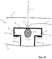
- the traction mechanism coupling device 12 can be transferred to the fixed setting by rotating the cam 28 about an axis of rotation 29 which corresponds to its longitudinal central axis (and runs perpendicular to the plane of the drawing), which is shown in figure 10 is shown.
- the traction mechanism 4 is clamped between the traction mechanism coupling device housing 26 and the cam 28, while in the release setting, shown in FIG figure 9 is shown, is not clamped between the traction mechanism coupling device housing 26 and the cam 28, so that the vertical end position of the bottom rail 8 can be adjusted when the blind is fully extended.
Landscapes
- Engineering & Computer Science (AREA)
- Structural Engineering (AREA)
- Architecture (AREA)
- Civil Engineering (AREA)
- Blinds (AREA)
Applications Claiming Priority (1)
| Application Number | Priority Date | Filing Date | Title |
|---|---|---|---|
| LU102270A LU102270B1 (de) | 2020-12-03 | 2020-12-03 | Raffstore und Verfahren zum Modifizieren eines Raffstores |
Publications (1)
| Publication Number | Publication Date |
|---|---|
| EP4008875A1 true EP4008875A1 (fr) | 2022-06-08 |
Family
ID=74418506
Family Applications (1)
| Application Number | Title | Priority Date | Filing Date |
|---|---|---|---|
| EP21211922.6A Withdrawn EP4008875A1 (fr) | 2020-12-03 | 2021-12-02 | Store vénitien et procédé de modification d'un store vénitien |
Country Status (3)
| Country | Link |
|---|---|
| EP (1) | EP4008875A1 (fr) |
| DE (1) | DE202021004186U1 (fr) |
| LU (1) | LU102270B1 (fr) |
Citations (2)
| Publication number | Priority date | Publication date | Assignee | Title |
|---|---|---|---|---|
| DE202009015473U1 (de) * | 2009-02-05 | 2010-05-20 | Roma Rolladensysteme Gmbh | Lamellenjalousie |
| DE202017000322U1 (de) * | 2017-01-13 | 2017-03-16 | Alukon Kg | Raffstore aus Raffstorelamellen |
-
2020
- 2020-12-03 LU LU102270A patent/LU102270B1/de active IP Right Grant
-
2021
- 2021-12-02 DE DE202021004186.9U patent/DE202021004186U1/de active Active
- 2021-12-02 EP EP21211922.6A patent/EP4008875A1/fr not_active Withdrawn
Patent Citations (2)
| Publication number | Priority date | Publication date | Assignee | Title |
|---|---|---|---|---|
| DE202009015473U1 (de) * | 2009-02-05 | 2010-05-20 | Roma Rolladensysteme Gmbh | Lamellenjalousie |
| DE202017000322U1 (de) * | 2017-01-13 | 2017-03-16 | Alukon Kg | Raffstore aus Raffstorelamellen |
Also Published As
| Publication number | Publication date |
|---|---|
| DE202021004186U1 (de) | 2023-01-13 |
| LU102270B1 (de) | 2022-06-07 |
Similar Documents
| Publication | Publication Date | Title |
|---|---|---|
| EP0082302B1 (fr) | Dispositif de protection contre le rayonnement solaire et/ou les intempéries | |
| EP2452034B1 (fr) | Dispositif à enroulement pour l'occlusion d'ouvertures pratiquées dans des murs ou de fenêtres | |
| AT510762B1 (de) | Seilzugeinrichtung, insbesondere prospektzuganlage für eine bühne oder dgl. | |
| EP2305943B1 (fr) | Agencement de rideaux pour une ouverture architectonique | |
| EP4008875A1 (fr) | Store vénitien et procédé de modification d'un store vénitien | |
| DE4105865C2 (de) | Vorrichtung zum Auf- und Abwickeln von Behängen, insbesondere Markisenstoffen, Rolläden, Gittern oder dergleichen | |
| EP1589627B1 (fr) | Dispositif de levage et de fixation pour barres omnibus | |
| DE102015117707A1 (de) | Antriebsvorrichtung zum Antreiben einer Verdunklungsvorrichtung, insbesondere eines Rollladens oder einer Jalousie | |
| DE10336943A1 (de) | Wickeljalousie | |
| DE20204939U1 (de) | Seitenverschattung für Gelenkarmmarkisen | |
| DE102016124955A1 (de) | Verriegelungsvorrichtung eines Verriegelungssystems, Verriegelungssystem sowie Schiebewandanlage | |
| DE102015017190B4 (de) | Antriebsvorrichtung zum Antreiben eines Rollladens | |
| LU102269B1 (de) | Raffstore und Verfahren zum Modifizieren eines Raffstores | |
| DE102024118753B4 (de) | Sonnenschutzrollo für eine fahrzeugscheibe | |
| EP4279697B1 (fr) | Porte avec dispositif d'entraînement | |
| EP4008874A1 (fr) | Store vénitien et procédé de modification d'un store vénitien | |
| DE20005567U1 (de) | Sonnenschutzanlage mit gegen Ausfall gesichertem Antrieb | |
| DE102005015902B4 (de) | Verfahrbare Hubvorrichtung | |
| DE102014105647B3 (de) | Torantriebsbefestigungsvorrichtung und damit versehene Torantriebsvorrichtung | |
| DE102022105035A1 (de) | Wandhalter zum Befestigen eines Führungselements einer Sonnenschutzanlage sowie Sonnenschutzanlage | |
| DE202017100061U1 (de) | Seilgetragenes Rollo sowie Rolloanordnung mit einem solchen Rollo | |
| DE202016105975U1 (de) | Beschattungsvorrichtung | |
| EP4474611A1 (fr) | Ouverture de bâtiment dotée d'un dispositif de protection | |
| EP4474610A1 (fr) | Dispositif de protection pour une ouverture de bâtiment et ouverture de bâtiment dotée d'un tel dispositif de protection | |
| EP1182320A1 (fr) | Volet roulant |
Legal Events
| Date | Code | Title | Description |
|---|---|---|---|
| PUAI | Public reference made under article 153(3) epc to a published international application that has entered the european phase |
Free format text: ORIGINAL CODE: 0009012 |
|
| STAA | Information on the status of an ep patent application or granted ep patent |
Free format text: STATUS: THE APPLICATION HAS BEEN PUBLISHED |
|
| AK | Designated contracting states |
Kind code of ref document: A1 Designated state(s): AL AT BE BG CH CY CZ DE DK EE ES FI FR GB GR HR HU IE IS IT LI LT LU LV MC MK MT NL NO PL PT RO RS SE SI SK SM TR |
|
| STAA | Information on the status of an ep patent application or granted ep patent |
Free format text: STATUS: THE APPLICATION IS DEEMED TO BE WITHDRAWN |
|
| 18D | Application deemed to be withdrawn |
Effective date: 20221209 |