EP4008970B1 - Unterstation für wärmequelle und entsprechendes betriebsverfahren - Google Patents
Unterstation für wärmequelle und entsprechendes betriebsverfahren Download PDFInfo
- Publication number
- EP4008970B1 EP4008970B1 EP21211799.8A EP21211799A EP4008970B1 EP 4008970 B1 EP4008970 B1 EP 4008970B1 EP 21211799 A EP21211799 A EP 21211799A EP 4008970 B1 EP4008970 B1 EP 4008970B1
- Authority
- EP
- European Patent Office
- Prior art keywords
- storage device
- thermal storage
- absorption machine
- supply inlet
- distribution circuit
- Prior art date
- Legal status (The legal status is an assumption and is not a legal conclusion. Google has not performed a legal analysis and makes no representation as to the accuracy of the status listed.)
- Active
Links
Images




Classifications
-
- F—MECHANICAL ENGINEERING; LIGHTING; HEATING; WEAPONS; BLASTING
- F24—HEATING; RANGES; VENTILATING
- F24D—DOMESTIC- OR SPACE-HEATING SYSTEMS, e.g. CENTRAL HEATING SYSTEMS; DOMESTIC HOT-WATER SUPPLY SYSTEMS; ELEMENTS OR COMPONENTS THEREFOR
- F24D10/00—District heating systems
- F24D10/003—Domestic delivery stations having a heat exchanger
-
- F—MECHANICAL ENGINEERING; LIGHTING; HEATING; WEAPONS; BLASTING
- F24—HEATING; RANGES; VENTILATING
- F24F—AIR-CONDITIONING; AIR-HUMIDIFICATION; VENTILATION; USE OF AIR CURRENTS FOR SCREENING
- F24F5/00—Air-conditioning systems or apparatus not covered by F24F1/00 or F24F3/00, e.g. using solar heat or combined with household units such as an oven or water heater
- F24F5/0007—Air-conditioning systems or apparatus not covered by F24F1/00 or F24F3/00, e.g. using solar heat or combined with household units such as an oven or water heater cooling apparatus specially adapted for use in air-conditioning
- F24F5/0014—Air-conditioning systems or apparatus not covered by F24F1/00 or F24F3/00, e.g. using solar heat or combined with household units such as an oven or water heater cooling apparatus specially adapted for use in air-conditioning using absorption or desorption
-
- F—MECHANICAL ENGINEERING; LIGHTING; HEATING; WEAPONS; BLASTING
- F24—HEATING; RANGES; VENTILATING
- F24F—AIR-CONDITIONING; AIR-HUMIDIFICATION; VENTILATION; USE OF AIR CURRENTS FOR SCREENING
- F24F5/00—Air-conditioning systems or apparatus not covered by F24F1/00 or F24F3/00, e.g. using solar heat or combined with household units such as an oven or water heater
- F24F5/0096—Air-conditioning systems or apparatus not covered by F24F1/00 or F24F3/00, e.g. using solar heat or combined with household units such as an oven or water heater combined with domestic apparatus
-
- F—MECHANICAL ENGINEERING; LIGHTING; HEATING; WEAPONS; BLASTING
- F24—HEATING; RANGES; VENTILATING
- F24D—DOMESTIC- OR SPACE-HEATING SYSTEMS, e.g. CENTRAL HEATING SYSTEMS; DOMESTIC HOT-WATER SUPPLY SYSTEMS; ELEMENTS OR COMPONENTS THEREFOR
- F24D2200/00—Heat sources or energy sources
- F24D2200/12—Heat pump
- F24D2200/126—Absorption type heat pumps
-
- Y—GENERAL TAGGING OF NEW TECHNOLOGICAL DEVELOPMENTS; GENERAL TAGGING OF CROSS-SECTIONAL TECHNOLOGIES SPANNING OVER SEVERAL SECTIONS OF THE IPC; TECHNICAL SUBJECTS COVERED BY FORMER USPC CROSS-REFERENCE ART COLLECTIONS [XRACs] AND DIGESTS
- Y02—TECHNOLOGIES OR APPLICATIONS FOR MITIGATION OR ADAPTATION AGAINST CLIMATE CHANGE
- Y02B—CLIMATE CHANGE MITIGATION TECHNOLOGIES RELATED TO BUILDINGS, e.g. HOUSING, HOUSE APPLIANCES OR RELATED END-USER APPLICATIONS
- Y02B30/00—Energy efficient heating, ventilation or air conditioning [HVAC]
- Y02B30/17—District heating
Definitions
- the present invention relates to the field of managing a heat source for the production of domestic hot water (DHW), heating or cooling.
- DHW domestic hot water
- It relates more particularly to a substation for a heat source for the production of heating and cooling, and an associated operating method.
- an absorption machine can be used for a production of hot water at an average temperature (for example between 40 and 65°C). This use is interesting because it offers a coefficient of performance greater than 1, saving heat from the primary network.
- An example of the architecture of a water production system at an average temperature of 45°C by absorption machine coupled with a heat network and a geothermal well is described in article No. 109403 of Z. Song, N. Wang, S. You et al., 2019, published in the journal “Energy & Buildings”, vol. 202 .
- An object of the present invention is therefore to propose a heat source substation and an associated operating method which make it possible to overcome at least the drawbacks of the prior art.
- a heat source substation according to the appended claim 1 is provided.
- the substation as introduced above may further have at least any one of the following features which may be taken separately or in combination.
- the absorption machine can be intended to be thermally coupled with a cooling circuit or cold source.
- the substation further includes a mechanical vapor compression machine coupled to the absorption machine.
- the system may further comprise at least one additional thermal storage device arranged on at least one of a supply pipe of the heating and cooling distribution circuit and a supply pipe of the domestic hot water distribution circuit.
- the heating and cooling distribution circuit and the domestic hot water distribution circuit may comprise the same supply pipe and/or the same return pipe. Where appropriate, the heating and cooling distribution circuit and the domestic hot water distribution circuit domestic hot water are used alternately.
- the method of operation as introduced above may further have at least any of the following steps which may be taken separately or in combination.
- the invention relates to a substation 2 for a heat source 1.
- the substation 2 according to the first aspect of the invention comprises at least one absorption machine 21 and a heat exchanger 22.
- the heat exchanger 22 is intended to be thermally coupled with a domestic hot water distribution circuit 4.
- the absorption machine 21 implemented in this invention can be of working torque H 2 O/LiBr or NH 3 /H 2 O or others.
- it comprises: a generator, an absorber, an evaporator, a condenser and a solution pump.
- the solution pump is for example arranged between the absorber and the generator of the absorption machine 21.
- a solution expander can also be arranged between the absorber and the generator of the absorption machine 21.
- the absorption machine 21 makes it possible to carry out a single-stage and single-effect absorption cycle.
- the condenser and the generator of the absorption machine 21 can work at a higher pressure than the evaporator and the absorber of the absorption machine 21.
- the temperature of the solution can be maximum at the generator of the absorption machine 21 and can be minimum at the evaporator of the absorption machine 21.
- the invention according to its first aspect therefore relates to a sub-element, called “substation 2”, of a system for producing heat for domestic hot water, heating and/or cooling, from a heat source 1.
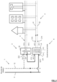
- a first of the three illustrated circuits represents the heat source circuit 1 (in bold on the left).
- a second of the three illustrated circuits represents the heating and cooling distribution circuit 3 (bottom right).
- a third of the three illustrated circuits represents the hot water distribution circuit (top right).
- Each of these circuits is represented by at least one solid line pipe and at least one dashed line pipe.
- the solid line pipes are so-called “supply” pipes.
- the dashed pipes are so-called “return” pipes, or equivalently “loop” pipes.
- a substation 2 according to the first aspect of the invention can be provided for a set of houses or for a building or for a factory, or for any combination thereof.
- several substations 2 according to the first aspect of the invention can be distributed along the circuit of the heat source 1 so that the production system can be deployed for the benefit of different sets of users.
- Different heat sources 1 are conceivable, and this indifferently, for each of the embodiments/operations described below.
- a heat network a fatal heat recovery network
- a solar heat capture device a thermal storage device (of which a supply inlet is in fluid connection with the supply pipe 11 of the heat source 1 and of which an evacuation outlet is in fluid connection with the return pipe 12 of the heat source 1) or a combination of one or more of these different heat sources 1.
- a thermal storage device of which a supply inlet is in fluid connection with the supply pipe 11 of the heat source 1 and of which an evacuation outlet is in fluid connection with the return pipe 12 of the heat source 1
- a combination of one or more of these different heat sources 1 1.
- the embodiments described above consider a heat network as heat source 1.
- the heat network 1, and more particularly a supply pipe 11 of the heat network 1, supplies the absorption machine 21 to its generator with hot water, at a temperature for example around 120°C.
- the absorption machine 21 thus produces cold at its evaporator, for example at a temperature substantially equal to 12°C, for a cooling requirement.
- the heat rejection at the condensers and the absorber of the absorption machine 21 is done through a cooling circuit 5.
- the latter can be connected with, or include, either a geothermal source, or with air heaters, or a combination of the two.
- Hot water comes out of the absorption machine 21, at a temperature as for example around 90°C, to then enter the heat exchanger 22 and thus provide heat to the DHW circuit 4. Leaving the heat exchanger 22, the hot water is at a temperature for example around 70°C and it then returns to the heat network 1, and more particularly to a return pipe 12 of the heat network 1.
- the two pipes illustrating the heating and cooling distribution circuit 3 are used to transport cold and the two pipes of the DHW circuit 4 are used to transport DHW.
- the DHW circuit 4 can also be used to provide heating if necessary.
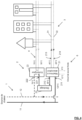
- FIG. 2 illustrated is a production mode designed to meet the needs of end users mainly in winter.
- the heat network 1, and more particularly a supply pipe 11 of the heat network 1, supplies the absorption machine 21 to its generator with hot water, at a temperature for example around 120°C.
- the absorption machine 21 thus produces water at a low temperature, for example substantially equal to 40°C, or at an average temperature, for example between 40 and 65°C, at its absorber and its condenser to be used for heating the end users.
- the evaporator of the absorption machine 21 is in contact with an intermediate circuit making it possible to take heat from a cold source, which is either geothermal, or composed of air heaters, or a combination of the two.
- the hot water leaves the absorption machine 21 at a temperature of around 90°C and then enters the heat exchanger 22 to provide heat to the DHW circuit 4. Leaving the heat exchanger 22, the hot water has a temperature of, for example, around 70°C and it then returns to the heat network 1, and more particularly to a return pipe 12 of the heat network.
- two pipes illustrating the heating and cooling distribution circuit 3 are used to transport heating and the two pipes of the DHW circuit 4 are used to transport DHW.
- the DHW circuit 4 can also be used to provide heating if necessary.
- substation 2 includes the same functional elements, namely essentially the absorber 21 and the heat exchanger 22. What allows these same functional elements to produce either cold or heating, in addition to providing heat for domestic hot water, consists of a variation of the fluid connections between these functional elements.
- This operating mode is a variant of the first operating mode described above. The only difference is that: the hot water, which is used to supply the absorption machine 21 then leaves it in a thermal storage device 23, before entering the heat exchanger 22.
- the thermal storage device 23 advantageously plays the role of buffer. More particularly, when there is a call for power to produce heat for the DHW, the thermal storage device 23 discharges heat to supply it to the domestic hot water distribution circuit 4 through the heat exchanger 22. This operating mode is particularly interesting for smoothing out the DHW power call peaks.
- the same principle as described above with reference to the figure 3 is applicable to heating production to meet the needs of end users in winter.
- excess heat from the heat network 1 is first stored in the thermal storage device 31.
- the inlet of the thermal storage device 23 is fluidically connected to the supply line 11 of the heat network 1 and the outlet of the thermal storage device 23 is fluidically connected to the return line 12 of the heat network 1.
- These fluid connections between the heat network 1 and the thermal storage device 23 can then be switched, so that the storage device 23 replaces, with respect to the absorption machine 21 and the heat exchanger 22, the heat network 1, by being connected to the absorption machine 21 and the heat exchanger 22 in the manner illustrated in the figure 5 .
- the thermal storage device 23 can be used in discharge to power the absorption machine 21 and in particular to provide heat for the DHW and to produce heating or cold.
- This mode of operation is particularly interesting because it allows the use of heat from network 1 to be optimized.
- thermo storage devices downstream of substation 2 it is possible to integrate additional thermal storage devices downstream of substation 2 to store DHW, heating water or cold water.
- each substation 2 described above may further comprise a mechanical vapor compression machine coupled to the absorption machine 21.
- the two distribution circuits namely the heating or cooling distribution circuit 3 and the DHW distribution circuit 4
- the heating and cooling distribution circuit (3) and the domestic hot water distribution circuit (4) can comprise the same supply pipe and/or the same return pipe for distributing either DHW or cooling or heating, and that the number of pipes in the production system can thus be advantageously reduced to three, or even two, pipes, including at least one supply pipe and one return pipe.
Landscapes
- Engineering & Computer Science (AREA)
- General Engineering & Computer Science (AREA)
- Chemical & Material Sciences (AREA)
- Combustion & Propulsion (AREA)
- Mechanical Engineering (AREA)
- Sustainable Development (AREA)
- Life Sciences & Earth Sciences (AREA)
- Physics & Mathematics (AREA)
- Thermal Sciences (AREA)
- Sorption Type Refrigeration Machines (AREA)
- Heat-Pump Type And Storage Water Heaters (AREA)
- Other Air-Conditioning Systems (AREA)
- Steam Or Hot-Water Central Heating Systems (AREA)
Claims (11)
- Unterstation (2) für Wärmequelle (1), die eine Absorptionsmaschine (21) und einen Wärmetauscher (22) umfasst,wobei ein erster Versorgungseingang (211) der Absorptionsmaschine (21) dazu bestimmt ist, strömungstechnisch in Verbindung mit einer Vorlaufleitung (11) der Wärmequelle (1) zu stehen,ein Austragsausgang (222) des Wärmetauschers (22) dazu bestimmt ist, strömungstechnisch in Verbindung mit einer Rücklaufleitung (12) der Wärmequelle (1) zu stehen,ein erster Austragsausgang (212) der Absorptionsmaschine (21) strömungstechnisch in Verbindung mit einem Versorgungseingang (221) des Wärmetauschers (22) steht, ein zweiter Austragsausgang (213) der Absorptionsmaschine (21) dazu bestimmt ist, strömungstechnisch in Verbindung mit einer Vorlaufleitung (31) eine Heiz- und Kühlverteilungskreislaufs (3) zu stehen, undein zweiter Versorgungseingang (214) der Absorptionsmaschine (21) strömungstechnisch in Verbindung mit einer Rücklaufleitung (32) des Heiz- und Kühlverteilungskreislaufs (3) steht, undwobei der Wärmetauscher (22) dazu bestimmt ist, thermisch mit einem Brauchwarmwasserverteilungskreislauf (4) gekoppelt zu sein;wobei die Absorptionsmaschine (21) einen Generator, einen Absorber, einen Verdampfer, einen Kondensator und eine Lösungspumpe umfasst,dadurch gekennzeichnet, dass die Unterstation weiter mindestens einen sogenannten "Frühjahr-Winter"-Fluidumschalter umfasst, der angeordnet ist, um die Unterstation umzuschalten zwischen:- einer Konfiguration zum Erzeugen von Wärme im Brauchwarmwasserverteilungskreislauf (4) und von Kälte im Heiz- und Kühlverteilungskreislauf (3), in welcher der zweite Austragsausgang (213) der Absorptionsmaschine (21) ein Austragsausgang des Verdampfers der Absorptionsmaschine (21) ist, und der zweite Versorgungseingang (214) der Absorptionsmaschine (21) ein Versorgungseingang des Verdampfers der Absorptionsmaschine (21) ist, und in welcher die Absorptionsmaschine (21) dazu bestimmt ist, thermisch mit einem Kühlkreislauf (5) gekoppelt zu werden, und- einer Konfiguration zum Erzeugen von Wärme im Brauchwarmwasserverteilungskreislauf (4) und von Heizung im Heiz- und Kühlverteilungskreislauf (3), in welcher der zweite Austragsausgang (213) der Absorptionsmaschine (21) ein Austragsausgang des Kondensators der Absorptionsmaschine (21) ist, und der zweite Versorgungseingang (214) der Absorptionsmaschine (21) ein Versorgungseingang des Absorbers der Absorptionsmaschine (21) ist, und in der die Absorptionsmaschine (21) dazu bestimmt ist, thermisch mit einem Kältequellenkreislauf (6) gekoppelt zu werden.
- Unterstation (2) nach dem vorstehenden Anspruch, wobei die Absorptionsmaschine (21) dazu bestimmt ist, thermisch mit einem Kühl- (5) oder einem Kältequellenkreislauf (6) gekoppelt zu werden.
- Unterstation (2) nach einem der vorstehenden Ansprüche:- weiter umfassend eine thermische Speichervorrichtung (23), die einen Versorgungseingang und einen Austragsausgang umfasst, wobei die thermische Speichervorrichtung (23) beispielsweise aus einer thermischen Speichervorrichtung durch flüssiges Wasser mit oder ohne Druckaufschlag, und einer thermischen Speichervorrichtung durch einen Phasenänderungswerkstoff ausgewählt ist, und- wobei der Versorgungseingang der thermischen Speichervorrichtung (23) strömungstechnisch in Verbindung mit einem ersten Austragsausgang (212) der Absorptionsmaschine (21) steht und der Austragsausgang der thermischen Speichervorrichtung (23) strömungstechnisch in Verbindung mit dem Versorgungseingang (221) des Wärmetauschers (22) steht, wobei der erste Austragsausgang (212) der Absorptionsmaschine (21) über die thermische Speichervorrichtung (23) strömungstechnisch in Verbindung mit dem Versorgungseingang (221) des Wärmetauschers (22) steht.
- Unterstation (2) nach einem der Ansprüche 1 bis 2, weiter umfassend:- eine thermische Speichervorrichtung (23), die einen Versorgungseingang und einen Austragsausgang umfasst, wobei die thermische Speichervorrichtung (23) beispielsweise aus einer thermischen Speichervorrichtung durch flüssiges Wasser mit oder ohne Druckaufschlag, und einer thermischen Speichervorrichtung durch einen Phasenänderungswerkstoff ausgewählt ist, und- mindestens einen Fluidumschalter zum Laden und Entladen, der angeordnet ist, um die Unterstation umzuschalten zwischen:- einer Konfiguration zum Laden der thermischen Speichervorrichtung (23), in welcher der Versorgungseingang der thermischen Speichervorrichtung (23) dazu bestimmt ist, strömungstechnisch in Verbindung mit der Vorlaufleitung (11) der Wärmequelle (1) zu stehen, und der Austragsausgang der thermischen Speichervorrichtung (23) dazu bestimmt ist, strömungstechnisch in Verbindung mit der Rücklaufleitung (12) der Wärmequelle (1) zu stehen, und- einer Konfiguration zum Entladen der thermischen Speichervorrichtung (23), in welcher der Versorgungseingang der thermischen Speichervorrichtung (23) strömungstechnisch in Verbindung mit dem ersten Versorgungseingang (211) der Absorptionsmaschine (21) steht, und der Austragsausgang der thermischen Speichervorrichtung (23) strömungstechnisch in Verbindung mit dem Austragsausgang (222) des Wärmetauschers (22) steht.
- Unterstation (2) nach einem der Ansprüche 1 bis 2, weiter umfassend:- eine thermische Speichervorrichtung (23), die einen Versorgungseingang und einen Austragsausgang umfasst, wobei die thermische Speichervorrichtung (23) beispielsweise aus einer thermischen Speichervorrichtung durch flüssiges Wasser mit oder ohne Druckaufschlag, und einer thermischen Speichervorrichtung durch einen Phasenänderungswerkstoff ausgewählt ist, und- mindestens eine Steuereinheit zur Fluidverwaltung, die angeordnet ist, um eine Versorgungskonfiguration der Absorptionsmaschine durch die Wärmequelle (1) und/oder die thermische Speichervorrichtung (23) zu verwalten,in der:der Versorgungseingang der thermischen Speichervorrichtung (23) strömungstechnisch in Verbindung mit dem Austragsausgang (222) des Wärmetauschers (22) und/oder mit der Rücklaufleitung (12) der Wärmequelle (1) steht, undder Austragsausgang der thermischen Speichervorrichtung (23) strömungstechnisch in Verbindung mit dem ersten Versorgungseingang (211) der Absorptionsmaschine (21) und/oder mit der Vorlaufleitung (11) der Wärmequelle (1) steht.
- System zum Erzeugen von Wärme für warmes Brauchwasser (ECS), Heizung und Kühlung, umfassend eine Wärmequelle (1), mindestens einen Heiz- und Kühlverteilungskreislauf (3), mindestens einen Brauchwarmwasserverteilungskreislauf (4) und mindestens eine Unterstation (2) nach einem der vorstehenden Ansprüche, wobei die Wärmequelle mindestens eines umfasst aus:- einem Wärmenetz,- einem Abwärme-Rückgewinnungsnetz,- einer Vorrichtung zum Auffangen von Sonnenwärme,- einer thermischen Speichervorrichtung, von der ein Versorgungseingang strömungstechnisch in Verbindung mit der Vorlaufleitung (11) der Wärmequelle (1) steht, und von der ein Austragsausgang strömungstechnisch in Verbindung mit der Rücklaufleitung (12) der Wärmequelle (1) steht.
- System nach dem vorstehenden Anspruch, wobei der Heiz- und Kühlverteilungskreislauf (3) und der Brauchwarmwasserverteilungskreislauf (4) eine gleiche Vorlaufleitung und/oder eine gleiche Rücklaufleitung umfassen, wobei gegebenenfalls der Heiz- und Kühlverteilungskreislauf (3) und der Brauchwarmwasserverteilungskreislauf (4) abwechselnd verwendet werden.
- Verfahren zum Betreiben einer Unterstation (2) einer Wärmequelle (1), die eine Absorptionsmaschine (21) und einen Wärmetauscher (22) umfasst,wobei ein erster Versorgungseingang (211) der Absorptionsmaschine (21) dazu bestimmt ist, strömungstechnisch in Verbindung mit einer Vorlaufleitung (11) der Wärmequelle (1) zu stehen,ein Austragsausgang (222) des Wärmetauschers (22) dazu bestimmt ist, strömungstechnisch in Verbindung mit einer Rücklaufleitung (12) der Wärmequelle (1) zu stehen,ein erster Austragsausgang (212) der Absorptionsmaschine (21) strömungstechnisch in Verbindung mit einem Versorgungseingang (221) des Wärmetauschers (22) steht, ein zweiter Austragsausgang (213) der Absorptionsmaschine (21) dazu bestimmt ist, strömungstechnisch in Verbindung mit einer Vorlaufleitung (31) eines Heiz- und Kühlverteilungskreislaufs (3) zu stehen, undein zweiter Versorgungseingang (214) der Absorptionsmaschine (21) strömungstechnisch in Verbindung mit einer Rücklaufleitung (32) des Heiz- und Kühlverteilungskreislaufs (3) steht,wobei der Wärmetauscher (22) dazu bestimmt ist, thermisch mit einem Brauchwarmwasserverteilungskreislauf (4) gekoppelt zu sein;wobei das Verfahren dergestalt ist, dass die Absorptionsmaschine (21) verwendet wird, um neben der Wärme für den Brauchwarmwasserverteilungskreislauf (4) über den Wärmetauscher (22) dem Heiz- und Kühlverteilungskreislauf (3) abwechselnd Heizung und Kühlung bereitzustellen,wobei die Absorptionsmaschine (21) einen Generator, einen Absorber, einen Verdampfer, einen Kondensator und eine Lösungspumpe umfasst,wobei das Verfahren weiter mindestens einen Schritt zum Umschalten der Unterstation durch den Einsatz eines sogenannten "Frühjahr-Winter"-Fluidumschalters umfasst, zwischen:- einer Konfiguration zum Erzeugen von Wärme im Brauchwarmwasserverteilungskreislauf (4) und von Kälte im Heiz- und Kühlverteilungskreislauf (3), durch:∘ thermisches Koppeln der Absorptionsmaschine (21) mit einem Kühlkreislauf (5),∘ Versorgen der Absorptionsmaschine (21) über einen Versorgungseingang des Verdampfers der Absorptionsmaschine (21) als zweiten Versorgungseingang (214) der Absorptionsmaschine (21), und∘ Austragen aus der Absorptionsmaschine (21) durch einen Austragsausgang des Verdampfers der Absorptionsmaschine (21) als zweiten Ausgang (213) der Absorptionsmaschine (21),um dem Brauchwarmwasserverteilungskreislauf (4) Wärme bereitzustellen, und im Heiz- und Kühlverteilungskreislauf (3) Kälte zu erzeugen,- einer Konfiguration zum Erzeugen von Wärme im Brauchwarmwasserverteilungskreislauf (4) und von Heizung im Heiz- und Kühlverteilungskreislauf (3), durch:∘ thermisches Koppeln der Absorptionsmaschine (21) mit einem Kältequellenkreislauf (6),∘ Versorgen der Absorptionsmaschine (21) durch einen Versorgungseingang des Absorbers der Absorptionsmaschine (21) als zweiten Versorgungseingang (214) der Absorptionsmaschine (21), und∘ Austragen aus der Absorptionsmaschine (21) durch einen Austragsausgang des Kondensators der Absorptionsmaschine (21) als zweiten Ausgang (213) der Absorptionsmaschine (21),um dem Brauchwarmwasserverteilungskreislauf (4) Wärme bereitzustellen und um im Heiz- und Kühlverteilungskreislauf (3) Heizung zu erzeugen.
- Verfahren zum Betreiben nach dem vorstehenden Anspruch, wobei das Verfahren mit der Unterstation, die weiter eine thermische Speichervorrichtung (23) umfasst, weiter umfasst:- das Glätten von Leistungsabrufspitzen im Brauchwarmwasserverteilungskreislauf (4) durch den Einsatz der der thermischen Speichervorrichtung (23),wobei ein Versorgungseingang der thermischen Speichervorrichtung (23) strömungstechnisch in Verbindung mit einem ersten Austragsausgang (212) der Absorptionsmaschine (21) steht und der Austragsausgang der thermischen Speichervorrichtung (23) strömungstechnisch in Verbindung mit dem Versorgungseingang (221) des Wärmetauschers (22) steht, wobei der erste Austragsausgang (212) der Absorptionsmaschine (21) über die thermische Speichervorrichtung (23) strömungstechnisch in Verbindung mit dem Versorgungseingang (221) des Wärmetauschers (22) steht.
- Verfahren zum Betreiben nach einem der Ansprüche 8 und 9, wobei mit der Unterstation (2), die weiter eine thermische Speichervorrichtung (23) und mindestens einen Fluidumschalter zum Laden und Entladen umfasst, dieser letztere angeordnet ist, um die Unterstation (2) umzuschalten zwischen:- einer Konfiguration zum Laden der thermischen Speichervorrichtung (23), in welcher der Versorgungseingang der thermischen Speichervorrichtung (23) dazu bestimmt ist, strömungstechnisch in Verbindung mit der Vorlaufleitung (11) der Wärmequelle (1) zu stehen, und der Austragsausgang der thermischen Speichervorrichtung (23) dazu bestimmt ist, strömungstechnisch in Verbindung mit der Rücklaufleitung (12) der Wärmequelle (1) zu stehen, und- einer Konfiguration zum Entladen der thermischen Speichervorrichtung (23), in welcher der Versorgungseingang der thermischen Speichervorrichtung (23) strömungstechnisch in Verbindung mit dem ersten Versorgungseingang (211) der Absorptionsmaschine (21) steht, und der Austragsausgang der thermischen Speichervorrichtung (23) strömungstechnisch in Verbindung mit dem Austragsausgang (222) des Wärmetauschers (22) steht,das Verfahren weiter umfasst:- das Glätten von Leistungsabrufspitzen im Brauchwarmwasserverteilungskreislauf (4) durch den Einsatz der thermischen Speichervorrichtung (23) und des Fluidumschalters zum Laden und Entladen.
- Verfahren zum Betreiben nach einem der Ansprüche 8 und 9, wobei mit der Unterstation (2), die weiter eine thermische Speichervorrichtung (23) und mindestens eine Steuereinheit zur Fluidverwaltung umfasst, wobei diese letztere angeordnet ist, um eine Versorgungskonfiguration der Absorptionsmaschine durch die Wärmequelle (1) und/oder die thermische Speichervorrichtung (23) zu verwalten, in welcher:- der Versorgungseingang der thermischen Speichervorrichtung (23) strömungstechnisch in Verbindung mit dem Austragsausgang (222) des Wärmetauschers (22) und/oder mit der Rücklaufleitung (12) der Wärmequelle (1) steht, und- der Austragsausgang der thermischen Speichervorrichtung (23) strömungstechnisch in Verbindung mit dem ersten Versorgungseingang (211) der Absorptionsmaschine (21) und/oder mit der Vorlaufleitung (11) der Wärmequelle (1) steht,das Verfahren weiter umfasst:- das Glätten von Leistungsabrufspitzen im Heiz- und Kühlverteilungskreislauf (3) und im Brauchwarmwasserverteilungskreislauf (4) durch den Einsatz der thermischen Speichervorrichtung (23) und der Steuereinheit zur Fluidverwaltung.
Applications Claiming Priority (1)
| Application Number | Priority Date | Filing Date | Title |
|---|---|---|---|
| FR2012546A FR3116888B1 (fr) | 2020-12-02 | 2020-12-02 | Sous-station pour source de chaleur et procédé de fonctionnement associé |
Publications (2)
| Publication Number | Publication Date |
|---|---|
| EP4008970A1 EP4008970A1 (de) | 2022-06-08 |
| EP4008970B1 true EP4008970B1 (de) | 2024-10-23 |
Family
ID=74183454
Family Applications (1)
| Application Number | Title | Priority Date | Filing Date |
|---|---|---|---|
| EP21211799.8A Active EP4008970B1 (de) | 2020-12-02 | 2021-12-01 | Unterstation für wärmequelle und entsprechendes betriebsverfahren |
Country Status (4)
| Country | Link |
|---|---|
| EP (1) | EP4008970B1 (de) |
| DK (1) | DK4008970T3 (de) |
| FI (1) | FI4008970T3 (de) |
| FR (1) | FR3116888B1 (de) |
Families Citing this family (1)
| Publication number | Priority date | Publication date | Assignee | Title |
|---|---|---|---|---|
| AU2024277719A1 (en) * | 2023-05-23 | 2025-12-04 | Snf Group | District heating plant and method |
Family Cites Families (3)
| Publication number | Priority date | Publication date | Assignee | Title |
|---|---|---|---|---|
| FI98858C (fi) * | 1994-01-24 | 1997-08-25 | Abb Installaatiot Oy | Menetelmä termisen energian jakelujärjestelmän yhteydessä ja termisen energian jakelujärjestelmä |
| KR102087862B1 (ko) * | 2018-10-31 | 2020-03-12 | 한국지역난방공사 | 지역난방과 지열을 연계한 급탕 히트 펌프 시스템 |
| KR102211617B1 (ko) * | 2019-03-25 | 2021-02-03 | 한국지역난방공사 | 난방효율을 증대하는 저온 지역난방 시스템 |
-
2020
- 2020-12-02 FR FR2012546A patent/FR3116888B1/fr active Active
-
2021
- 2021-12-01 FI FIEP21211799.8T patent/FI4008970T3/fi active
- 2021-12-01 EP EP21211799.8A patent/EP4008970B1/de active Active
- 2021-12-01 DK DK21211799.8T patent/DK4008970T3/da active
Also Published As
| Publication number | Publication date |
|---|---|
| FI4008970T3 (fi) | 2025-01-23 |
| EP4008970A1 (de) | 2022-06-08 |
| DK4008970T3 (da) | 2025-01-27 |
| FR3116888B1 (fr) | 2023-01-27 |
| FR3116888A1 (fr) | 2022-06-03 |
Similar Documents
| Publication | Publication Date | Title |
|---|---|---|
| EP2904220B1 (de) | Dampfwärmespeichersystem | |
| EP2263894B1 (de) | Wärmemanagmentsystem mit einem Klimaanlagenkreislauf und einem Kältemittelkreislauf | |
| FR2834778A1 (fr) | Dispositif de gestion thermique, notamment pour vehicule automobile equipe d'une pile a combustible | |
| FR2912995A1 (fr) | Dispositif de controle thermique embarque a bord d'un engin spatial | |
| EP4008970B1 (de) | Unterstation für wärmequelle und entsprechendes betriebsverfahren | |
| EP3172499B1 (de) | Kälteerzeugungsvorrichtung mit mittel zur gleichzeitigen kondensation durch luft und verfahren zur implementierung dieser einrichtung | |
| EP4132809A1 (de) | Anordnung zur kühlung einer brennstoffzelle und eines elektrischen antriebs- und/oder antriebsmotor eines fahrzeugs | |
| EP2827068B1 (de) | Wärmepumpe mit Kaskadenregelung | |
| FR3076600A1 (fr) | Systeme thermodynamique de chauffage, de climatisation et de production d'eau chaude sanitaire | |
| EP3225937A1 (de) | Vorrichtung für gebäude, die ein speicherelement für ein thermisch wiederaufladbares fluid enthält | |
| EP2984434B1 (de) | Thermochemisches speichersystem mit verbesserter speichereffizienz | |
| WO2002039033A1 (fr) | Systeme reversible de recuperation d'energie calorifique | |
| FR3042856B1 (fr) | Systeme de traitement d’air hybride solaire et thermodynamique | |
| EP3152410B1 (de) | Kraftwerk zur umwandlung von wärme in mechanische energie mit verbessertem arbeitsfluidkühlsystem | |
| FR2986860A1 (fr) | Installation thermique et procede assurant un conditionnement thermique d'un local et une production d'eau chaude sanitaire | |
| FR2934890A1 (fr) | Installation de pompe a chaleur pour le chauffage d'un fluide. | |
| FR2906604A1 (fr) | Module utilisable pour le stockage et le transfert thermique. | |
| FR3161727A1 (fr) | Installation thermique multifonctionnelle, comprenant une pompe à chaleur à quantité réduite de fluide frigorigène | |
| FR3036177A1 (fr) | Dispositif de stockage d'energie thermique | |
| EP4616433A1 (de) | Elektronuklear-heizkraftwerk mit leichtwasserreaktor und system zum abscheiden von atmosphärischem co2 oder zum entsalzen von meerwasser | |
| EP3152510B1 (de) | Anlage zur umwandlung von wärme in mechanische energie mit optimierter kühlung durch ein system zur rückgewinnung und speicherung eines teils der wärmeenergie der arbeitsflüssigkeit | |
| WO2019073177A1 (fr) | Systeme d'echangeurs de chaleur en particulier pour une trigeneration solaire | |
| EP3848659B1 (de) | Unterteilter wärmetauscher, rückgewinnungseinheit der wärmeenergie und entsprechende sterilisationsvorrichtung | |
| FR2909440A1 (fr) | Installation de pompe a chaleur a rendement ameliore, utilisant une serie d'echanges avec un fluide exterieur introduit en amont du detenteur | |
| FR3148831A1 (fr) | Dispositif de generation de fluides froid et chaud dans des phases distinctes |
Legal Events
| Date | Code | Title | Description |
|---|---|---|---|
| PUAI | Public reference made under article 153(3) epc to a published international application that has entered the european phase |
Free format text: ORIGINAL CODE: 0009012 |
|
| STAA | Information on the status of an ep patent application or granted ep patent |
Free format text: STATUS: REQUEST FOR EXAMINATION WAS MADE |
|
| 17P | Request for examination filed |
Effective date: 20211201 |
|
| AK | Designated contracting states |
Kind code of ref document: A1 Designated state(s): AL AT BE BG CH CY CZ DE DK EE ES FI FR GB GR HR HU IE IS IT LI LT LU LV MC MK MT NL NO PL PT RO RS SE SI SK SM TR |
|
| GRAP | Despatch of communication of intention to grant a patent |
Free format text: ORIGINAL CODE: EPIDOSNIGR1 |
|
| STAA | Information on the status of an ep patent application or granted ep patent |
Free format text: STATUS: GRANT OF PATENT IS INTENDED |
|
| RIC1 | Information provided on ipc code assigned before grant |
Ipc: F24F 5/00 20060101ALI20240422BHEP Ipc: F24D 10/00 20220101AFI20240422BHEP |
|
| INTG | Intention to grant announced |
Effective date: 20240522 |
|
| GRAS | Grant fee paid |
Free format text: ORIGINAL CODE: EPIDOSNIGR3 |
|
| GRAA | (expected) grant |
Free format text: ORIGINAL CODE: 0009210 |
|
| STAA | Information on the status of an ep patent application or granted ep patent |
Free format text: STATUS: THE PATENT HAS BEEN GRANTED |
|
| AK | Designated contracting states |
Kind code of ref document: B1 Designated state(s): AL AT BE BG CH CY CZ DE DK EE ES FI FR GB GR HR HU IE IS IT LI LT LU LV MC MK MT NL NO PL PT RO RS SE SI SK SM TR |
|
| REG | Reference to a national code |
Ref country code: GB Ref legal event code: FG4D Free format text: NOT ENGLISH |
|
| RAP4 | Party data changed (patent owner data changed or rights of a patent transferred) |
Owner name: COMPAGNIE DE CHAUFFAGE INTERCOMMUNALE DEL'AGGLOMERATION GRENOBLOISE Owner name: COMMISSARIAT A L'ENERGIE ATOMIQUE ET AUX ENERGIESALTERNATIVES |
|
| REG | Reference to a national code |
Ref country code: CH Ref legal event code: EP |
|
| REG | Reference to a national code |
Ref country code: DE Ref legal event code: R096 Ref document number: 602021020603 Country of ref document: DE |
|
| REG | Reference to a national code |
Ref country code: IE Ref legal event code: FG4D Free format text: LANGUAGE OF EP DOCUMENT: FRENCH |
|
| REG | Reference to a national code |
Ref country code: FI Ref legal event code: FGE |
|
| REG | Reference to a national code |
Ref country code: DK Ref legal event code: T3 Effective date: 20250120 |
|
| REG | Reference to a national code |
Ref country code: SE Ref legal event code: TRGR |
|
| REG | Reference to a national code |
Ref country code: LT Ref legal event code: MG9D |
|
| REG | Reference to a national code |
Ref country code: NL Ref legal event code: MP Effective date: 20241023 |
|
| REG | Reference to a national code |
Ref country code: AT Ref legal event code: MK05 Ref document number: 1735129 Country of ref document: AT Kind code of ref document: T Effective date: 20241023 |
|
| PG25 | Lapsed in a contracting state [announced via postgrant information from national office to epo] |
Ref country code: NL Free format text: LAPSE BECAUSE OF FAILURE TO SUBMIT A TRANSLATION OF THE DESCRIPTION OR TO PAY THE FEE WITHIN THE PRESCRIBED TIME-LIMIT Effective date: 20241023 |
|
| PG25 | Lapsed in a contracting state [announced via postgrant information from national office to epo] |
Ref country code: NL Free format text: LAPSE BECAUSE OF FAILURE TO SUBMIT A TRANSLATION OF THE DESCRIPTION OR TO PAY THE FEE WITHIN THE PRESCRIBED TIME-LIMIT Effective date: 20241023 |
|
| PGFP | Annual fee paid to national office [announced via postgrant information from national office to epo] |
Ref country code: SE Payment date: 20250314 Year of fee payment: 4 |
|
| PG25 | Lapsed in a contracting state [announced via postgrant information from national office to epo] |
Ref country code: PT Free format text: LAPSE BECAUSE OF FAILURE TO SUBMIT A TRANSLATION OF THE DESCRIPTION OR TO PAY THE FEE WITHIN THE PRESCRIBED TIME-LIMIT Effective date: 20250224 Ref country code: HR Free format text: LAPSE BECAUSE OF FAILURE TO SUBMIT A TRANSLATION OF THE DESCRIPTION OR TO PAY THE FEE WITHIN THE PRESCRIBED TIME-LIMIT Effective date: 20241023 Ref country code: IS Free format text: LAPSE BECAUSE OF FAILURE TO SUBMIT A TRANSLATION OF THE DESCRIPTION OR TO PAY THE FEE WITHIN THE PRESCRIBED TIME-LIMIT Effective date: 20250223 |
|
| PGFP | Annual fee paid to national office [announced via postgrant information from national office to epo] |
Ref country code: DE Payment date: 20250207 Year of fee payment: 4 |
|
| PGFP | Annual fee paid to national office [announced via postgrant information from national office to epo] |
Ref country code: DK Payment date: 20250226 Year of fee payment: 4 Ref country code: FI Payment date: 20250224 Year of fee payment: 4 |
|
| PG25 | Lapsed in a contracting state [announced via postgrant information from national office to epo] |
Ref country code: BG Free format text: LAPSE BECAUSE OF FAILURE TO SUBMIT A TRANSLATION OF THE DESCRIPTION OR TO PAY THE FEE WITHIN THE PRESCRIBED TIME-LIMIT Effective date: 20241023 |
|
| PG25 | Lapsed in a contracting state [announced via postgrant information from national office to epo] |
Ref country code: ES Free format text: LAPSE BECAUSE OF FAILURE TO SUBMIT A TRANSLATION OF THE DESCRIPTION OR TO PAY THE FEE WITHIN THE PRESCRIBED TIME-LIMIT Effective date: 20241023 |
|
| PG25 | Lapsed in a contracting state [announced via postgrant information from national office to epo] |
Ref country code: NO Free format text: LAPSE BECAUSE OF FAILURE TO SUBMIT A TRANSLATION OF THE DESCRIPTION OR TO PAY THE FEE WITHIN THE PRESCRIBED TIME-LIMIT Effective date: 20250123 |
|
| PG25 | Lapsed in a contracting state [announced via postgrant information from national office to epo] |
Ref country code: LV Free format text: LAPSE BECAUSE OF FAILURE TO SUBMIT A TRANSLATION OF THE DESCRIPTION OR TO PAY THE FEE WITHIN THE PRESCRIBED TIME-LIMIT Effective date: 20241023 Ref country code: AT Free format text: LAPSE BECAUSE OF FAILURE TO SUBMIT A TRANSLATION OF THE DESCRIPTION OR TO PAY THE FEE WITHIN THE PRESCRIBED TIME-LIMIT Effective date: 20241023 Ref country code: GR Free format text: LAPSE BECAUSE OF FAILURE TO SUBMIT A TRANSLATION OF THE DESCRIPTION OR TO PAY THE FEE WITHIN THE PRESCRIBED TIME-LIMIT Effective date: 20250124 |
|
| PG25 | Lapsed in a contracting state [announced via postgrant information from national office to epo] |
Ref country code: PL Free format text: LAPSE BECAUSE OF FAILURE TO SUBMIT A TRANSLATION OF THE DESCRIPTION OR TO PAY THE FEE WITHIN THE PRESCRIBED TIME-LIMIT Effective date: 20241023 |
|
| PG25 | Lapsed in a contracting state [announced via postgrant information from national office to epo] |
Ref country code: IT Free format text: LAPSE BECAUSE OF NON-PAYMENT OF DUE FEES Effective date: 20241201 |
|
| PG25 | Lapsed in a contracting state [announced via postgrant information from national office to epo] |
Ref country code: RS Free format text: LAPSE BECAUSE OF FAILURE TO SUBMIT A TRANSLATION OF THE DESCRIPTION OR TO PAY THE FEE WITHIN THE PRESCRIBED TIME-LIMIT Effective date: 20250123 |
|
| PG25 | Lapsed in a contracting state [announced via postgrant information from national office to epo] |
Ref country code: SM Free format text: LAPSE BECAUSE OF FAILURE TO SUBMIT A TRANSLATION OF THE DESCRIPTION OR TO PAY THE FEE WITHIN THE PRESCRIBED TIME-LIMIT Effective date: 20241023 |
|
| PG25 | Lapsed in a contracting state [announced via postgrant information from national office to epo] |
Ref country code: MC Free format text: LAPSE BECAUSE OF FAILURE TO SUBMIT A TRANSLATION OF THE DESCRIPTION OR TO PAY THE FEE WITHIN THE PRESCRIBED TIME-LIMIT Effective date: 20241023 |
|
| PG25 | Lapsed in a contracting state [announced via postgrant information from national office to epo] |
Ref country code: EE Free format text: LAPSE BECAUSE OF FAILURE TO SUBMIT A TRANSLATION OF THE DESCRIPTION OR TO PAY THE FEE WITHIN THE PRESCRIBED TIME-LIMIT Effective date: 20241023 |
|
| PG25 | Lapsed in a contracting state [announced via postgrant information from national office to epo] |
Ref country code: RO Free format text: LAPSE BECAUSE OF FAILURE TO SUBMIT A TRANSLATION OF THE DESCRIPTION OR TO PAY THE FEE WITHIN THE PRESCRIBED TIME-LIMIT Effective date: 20241023 |
|
| REG | Reference to a national code |
Ref country code: DE Ref legal event code: R097 Ref document number: 602021020603 Country of ref document: DE |
|
| PG25 | Lapsed in a contracting state [announced via postgrant information from national office to epo] |
Ref country code: SK Free format text: LAPSE BECAUSE OF FAILURE TO SUBMIT A TRANSLATION OF THE DESCRIPTION OR TO PAY THE FEE WITHIN THE PRESCRIBED TIME-LIMIT Effective date: 20241023 |
|
| PG25 | Lapsed in a contracting state [announced via postgrant information from national office to epo] |
Ref country code: CZ Free format text: LAPSE BECAUSE OF FAILURE TO SUBMIT A TRANSLATION OF THE DESCRIPTION OR TO PAY THE FEE WITHIN THE PRESCRIBED TIME-LIMIT Effective date: 20241023 |
|
| REG | Reference to a national code |
Ref country code: CH Ref legal event code: PL |
|
| PG25 | Lapsed in a contracting state [announced via postgrant information from national office to epo] |
Ref country code: LU Free format text: LAPSE BECAUSE OF NON-PAYMENT OF DUE FEES Effective date: 20241201 |
|
| PLBE | No opposition filed within time limit |
Free format text: ORIGINAL CODE: 0009261 |
|
| STAA | Information on the status of an ep patent application or granted ep patent |
Free format text: STATUS: NO OPPOSITION FILED WITHIN TIME LIMIT |
|
| 26N | No opposition filed |
Effective date: 20250724 |
|
| REG | Reference to a national code |
Ref country code: BE Ref legal event code: MM Effective date: 20241231 |
|
| PG25 | Lapsed in a contracting state [announced via postgrant information from national office to epo] |
Ref country code: BE Free format text: LAPSE BECAUSE OF NON-PAYMENT OF DUE FEES Effective date: 20241231 |
|
| PG25 | Lapsed in a contracting state [announced via postgrant information from national office to epo] |
Ref country code: CH Free format text: LAPSE BECAUSE OF NON-PAYMENT OF DUE FEES Effective date: 20241231 |
|
| PG25 | Lapsed in a contracting state [announced via postgrant information from national office to epo] |
Ref country code: IE Free format text: LAPSE BECAUSE OF NON-PAYMENT OF DUE FEES Effective date: 20241201 |
|
| PG25 | Lapsed in a contracting state [announced via postgrant information from national office to epo] |
Ref country code: IT Free format text: LAPSE BECAUSE OF NON-PAYMENT OF DUE FEES Effective date: 20241201 |
|
| PGFP | Annual fee paid to national office [announced via postgrant information from national office to epo] |
Ref country code: IT Payment date: 20241231 Year of fee payment: 4 |
|
| PGRI | Patent reinstated in contracting state [announced from national office to epo] |
Ref country code: IT Effective date: 20241231 |
|
| PGFP | Annual fee paid to national office [announced via postgrant information from national office to epo] |
Ref country code: FR Payment date: 20251222 Year of fee payment: 5 |
|
| PG25 | Lapsed in a contracting state [announced via postgrant information from national office to epo] |
Ref country code: CY Free format text: LAPSE BECAUSE OF FAILURE TO SUBMIT A TRANSLATION OF THE DESCRIPTION OR TO PAY THE FEE WITHIN THE PRESCRIBED TIME-LIMIT; INVALID AB INITIO Effective date: 20211201 |