EP4009010B1 - Messsystem zum ermitteln einer abgegebenen wasserstoffmenge sowie verfahren hierzu - Google Patents
Messsystem zum ermitteln einer abgegebenen wasserstoffmenge sowie verfahren hierzu Download PDFInfo
- Publication number
- EP4009010B1 EP4009010B1 EP20211219.9A EP20211219A EP4009010B1 EP 4009010 B1 EP4009010 B1 EP 4009010B1 EP 20211219 A EP20211219 A EP 20211219A EP 4009010 B1 EP4009010 B1 EP 4009010B1
- Authority
- EP
- European Patent Office
- Prior art keywords
- hydrogen
- unit
- flowmeter
- measuring
- measuring system
- Prior art date
- Legal status (The legal status is an assumption and is not a legal conclusion. Google has not performed a legal analysis and makes no representation as to the accuracy of the status listed.)
- Active
Links
Images

Classifications
-
- G—PHYSICS
- G01—MEASURING; TESTING
- G01F—MEASURING VOLUME, VOLUME FLOW, MASS FLOW OR LIQUID LEVEL; METERING BY VOLUME
- G01F15/00—Details of, or accessories for, apparatus of groups G01F1/00 - G01F13/00 insofar as such details or appliances are not adapted to particular types of such apparatus
-
- F—MECHANICAL ENGINEERING; LIGHTING; HEATING; WEAPONS; BLASTING
- F17—STORING OR DISTRIBUTING GASES OR LIQUIDS
- F17C—VESSELS FOR CONTAINING OR STORING COMPRESSED, LIQUEFIED OR SOLIDIFIED GASES; FIXED-CAPACITY GAS-HOLDERS; FILLING VESSELS WITH, OR DISCHARGING FROM VESSELS, COMPRESSED, LIQUEFIED, OR SOLIDIFIED GASES
- F17C13/00—Details of vessels or of the filling or discharging of vessels
- F17C13/02—Special adaptations of indicating, measuring, or monitoring equipment
- F17C13/028—Special adaptations of indicating, measuring, or monitoring equipment having the volume as the parameter
-
- F—MECHANICAL ENGINEERING; LIGHTING; HEATING; WEAPONS; BLASTING
- F17—STORING OR DISTRIBUTING GASES OR LIQUIDS
- F17C—VESSELS FOR CONTAINING OR STORING COMPRESSED, LIQUEFIED OR SOLIDIFIED GASES; FIXED-CAPACITY GAS-HOLDERS; FILLING VESSELS WITH, OR DISCHARGING FROM VESSELS, COMPRESSED, LIQUEFIED, OR SOLIDIFIED GASES
- F17C5/00—Methods or apparatus for filling containers with liquefied, solidified, or compressed gases under pressures
- F17C5/06—Methods or apparatus for filling containers with liquefied, solidified, or compressed gases under pressures for filling with compressed gases
-
- G—PHYSICS
- G01—MEASURING; TESTING
- G01F—MEASURING VOLUME, VOLUME FLOW, MASS FLOW OR LIQUID LEVEL; METERING BY VOLUME
- G01F1/00—Measuring the volume flow or mass flow of fluid or fluent solid material wherein the fluid passes through a meter in a continuous flow
-
- G—PHYSICS
- G01—MEASURING; TESTING
- G01F—MEASURING VOLUME, VOLUME FLOW, MASS FLOW OR LIQUID LEVEL; METERING BY VOLUME
- G01F25/00—Testing or calibration of apparatus for measuring volume, volume flow or liquid level or for metering by volume
- G01F25/10—Testing or calibration of apparatus for measuring volume, volume flow or liquid level or for metering by volume of flowmeters
- G01F25/15—Testing or calibration of apparatus for measuring volume, volume flow or liquid level or for metering by volume of flowmeters specially adapted for gas meters
-
- F—MECHANICAL ENGINEERING; LIGHTING; HEATING; WEAPONS; BLASTING
- F17—STORING OR DISTRIBUTING GASES OR LIQUIDS
- F17C—VESSELS FOR CONTAINING OR STORING COMPRESSED, LIQUEFIED OR SOLIDIFIED GASES; FIXED-CAPACITY GAS-HOLDERS; FILLING VESSELS WITH, OR DISCHARGING FROM VESSELS, COMPRESSED, LIQUEFIED, OR SOLIDIFIED GASES
- F17C2221/00—Handled fluid, in particular type of fluid
- F17C2221/01—Pure fluids
- F17C2221/012—Hydrogen
-
- F—MECHANICAL ENGINEERING; LIGHTING; HEATING; WEAPONS; BLASTING
- F17—STORING OR DISTRIBUTING GASES OR LIQUIDS
- F17C—VESSELS FOR CONTAINING OR STORING COMPRESSED, LIQUEFIED OR SOLIDIFIED GASES; FIXED-CAPACITY GAS-HOLDERS; FILLING VESSELS WITH, OR DISCHARGING FROM VESSELS, COMPRESSED, LIQUEFIED, OR SOLIDIFIED GASES
- F17C2250/00—Accessories; Control means; Indicating, measuring or monitoring of parameters
- F17C2250/04—Indicating or measuring of parameters as input values
- F17C2250/0404—Parameters indicated or measured
- F17C2250/0443—Flow or movement of content
-
- F—MECHANICAL ENGINEERING; LIGHTING; HEATING; WEAPONS; BLASTING
- F17—STORING OR DISTRIBUTING GASES OR LIQUIDS
- F17C—VESSELS FOR CONTAINING OR STORING COMPRESSED, LIQUEFIED OR SOLIDIFIED GASES; FIXED-CAPACITY GAS-HOLDERS; FILLING VESSELS WITH, OR DISCHARGING FROM VESSELS, COMPRESSED, LIQUEFIED, OR SOLIDIFIED GASES
- F17C2265/00—Effects achieved by gas storage or gas handling
- F17C2265/06—Fluid distribution
- F17C2265/065—Fluid distribution for refuelling vehicle fuel tanks
-
- F—MECHANICAL ENGINEERING; LIGHTING; HEATING; WEAPONS; BLASTING
- F17—STORING OR DISTRIBUTING GASES OR LIQUIDS
- F17C—VESSELS FOR CONTAINING OR STORING COMPRESSED, LIQUEFIED OR SOLIDIFIED GASES; FIXED-CAPACITY GAS-HOLDERS; FILLING VESSELS WITH, OR DISCHARGING FROM VESSELS, COMPRESSED, LIQUEFIED, OR SOLIDIFIED GASES
- F17C2270/00—Applications
- F17C2270/01—Applications for fluid transport or storage
- F17C2270/0134—Applications for fluid transport or storage placed above the ground
- F17C2270/0139—Fuel stations
-
- Y—GENERAL TAGGING OF NEW TECHNOLOGICAL DEVELOPMENTS; GENERAL TAGGING OF CROSS-SECTIONAL TECHNOLOGIES SPANNING OVER SEVERAL SECTIONS OF THE IPC; TECHNICAL SUBJECTS COVERED BY FORMER USPC CROSS-REFERENCE ART COLLECTIONS [XRACs] AND DIGESTS
- Y02—TECHNOLOGIES OR APPLICATIONS FOR MITIGATION OR ADAPTATION AGAINST CLIMATE CHANGE
- Y02E—REDUCTION OF GREENHOUSE GAS [GHG] EMISSIONS, RELATED TO ENERGY GENERATION, TRANSMISSION OR DISTRIBUTION
- Y02E60/00—Enabling technologies; Technologies with a potential or indirect contribution to GHG emissions mitigation
- Y02E60/30—Hydrogen technology
- Y02E60/32—Hydrogen storage
-
- Y—GENERAL TAGGING OF NEW TECHNOLOGICAL DEVELOPMENTS; GENERAL TAGGING OF CROSS-SECTIONAL TECHNOLOGIES SPANNING OVER SEVERAL SECTIONS OF THE IPC; TECHNICAL SUBJECTS COVERED BY FORMER USPC CROSS-REFERENCE ART COLLECTIONS [XRACs] AND DIGESTS
- Y02—TECHNOLOGIES OR APPLICATIONS FOR MITIGATION OR ADAPTATION AGAINST CLIMATE CHANGE
- Y02P—CLIMATE CHANGE MITIGATION TECHNOLOGIES IN THE PRODUCTION OR PROCESSING OF GOODS
- Y02P90/00—Enabling technologies with a potential contribution to greenhouse gas [GHG] emissions mitigation
- Y02P90/45—Hydrogen technologies in production processes
Definitions
- the invention relates to a measuring system for determining a quantity of hydrogen delivered at a hydrogen delivery point from a hydrogen delivery unit present there to a receiving tank.
- a measuring unit is provided in the measuring system for this purpose.
- the hydrogen delivery point can be, for example, a hydrogen filling station, with the hydrogen delivery unit being the corresponding filling point or column.
- the invention further relates to a method for determining the amount of hydrogen delivered by a hydrogen delivery point, in particular a hydrogen filling station, with a hydrogen delivery unit to a receiving tank.
- a hydrogen filling station network does not yet exist or is not yet sufficiently dense.
- Various national regulations must be observed. For example, in Germany it is necessary to check whether the quantity stated at the gas station, i.e. the amount of hydrogen filled and thus dispensed, corresponds to the quantity actually dispensed.
- a receiving tank is mounted on a trailer and has an integrated, high-precision scale. This tank is refueled using the hydrogen delivery unit. The weight gain, which is in the range of 1kg to 4kg, is then determined with high precision. This size is compared with the measurement size specified by the gas station in order to carry out calibration.
- the problem with these systems is that they are extremely sensitive and prone to errors.
- the tank and body usually weighs around 400kg, with only a fraction of the weight being refueled - 1kg to 4kg of hydrogen.
- the trailer on which the tank is located is very susceptible to environmental influences.
- the wind pressure load on the trailer is already visible on the scale. This means that the measurement can ideally only be carried out in good weather and in the summer months.
- the hydrogen released is currently being released into the environment without being used.
- a chimney must be set up at least 20 meters from the gas station to ensure that the hydrogen can be blown off safely.
- the invention is therefore based on the object of providing an efficient measuring system and measuring method with which the amount of hydrogen released from a hydrogen delivery unit to a receiving tank is measured.
- the measuring unit has a flow meter which can be arranged between the hydrogen delivery unit and the receiving tank. Furthermore, the measuring system is designed to establish a fluid-tight connection between the hydrogen delivery unit and the receiving tank and to direct the hydrogen released by the hydrogen delivery unit through the flow meter to the receiving tank. It is further provided that the flow meter has active cooling.
- a basic idea of the invention can be seen in the fact that it is possible with appropriate additional means to determine the amount of hydrogen released with high precision using a flow meter.
- the flow meter is usually at room temperature or outside temperature before delivery. This means that temperatures can range between +5°C and +40°C amount.
- the gaseous highly compressed hydrogen has a temperature of up to -40°C. The result of this is that the required high-precision flow meters would have a high zero point drift when carrying out measurements, so that the measurement accuracy required by calibration law could not be achieved.
- the active cooling is provided as external cooling of the flow meter.
- this can also mean that the active cooling is not part of the flow meter itself, but can be added as an additional component or unit.
- active cooling In principle, various options for active cooling are conceivable. For example, a Peltier element or a classic compressor cooling system can be used for this. However, it is preferred if the active cooling is carried out using an external cooling material. Dry ice is particularly suitable for this.
- a hydrogen filling station is considered a potentially explosive zone and is classified as Ex Zone 1. This means that all devices present there must be designed to be explosion-proof. This particularly shows the advantage of an external, in particular energy-free, cooling material, which can be dry ice, for example.
- Dry ice is non-flammable and has a temperature of approximately -78°C. It is generally inexpensive to obtain and, apart from the cold temperatures, easy to handle. This means that there are no problems with this Ex zone or the necessary explosion protection. Dry ice is solid carbon dioxide (CO 2 ). It also has the advantage that it is gaseous at outside temperature, i.e. it evaporates. In general, other cold storage devices are also suitable.
- a receiving device with thermal contact with the flow meter is formed in the measuring unit. This makes it possible to introduce the external cooling material into the receiving device and to cool the flow meter as efficiently and easily as possible.
- the receiving device can, for example, be designed like a trough.
- the receiving device can be designed, for example, as a cavity accessible from the outside.
- This can be implemented in the form of a simple chamber that has a corresponding flap so that it is accessible. Closing the flap can ensure that as few environmental influences as possible affect the flow meter via this chamber while a measurement is being carried out.
- the thermal coupling between the receiving device and the flow meter can be implemented in various ways.
- One possibility is to form a wall of the receiving device through part of the body of the flow meter. It is advisable to make the housing or body of the flowmeter solid and made of stainless steel so that good heat transfer takes place and the flowmeter is cooled well.
- a higher mass of this housing or the body of the flow meter requires longer and stronger cooling, but offers the advantage that temperature fluctuations occur less strongly during the measurement process.
- flow meters can be used as flow meters. Examples of this are a Coriolis flowmeter, an ultrasonic flowmeter or a flowmeter using critical nozzles. Of course, other types of flow meters that are suitable for measuring fluids, in particular gases, can also be used.
- connection for transmitting bidirectional infrared signals is provided between the hydrogen delivery unit and the receiving tank.
- the connection can be guided as a bypass around the measuring device, but also through the measuring device itself.
- connecting means for an infrared connection between the hydrogen delivery unit, i.e. the fuel pump, and the receiving tank, for example in a car, are provided in parallel within or on the tank hose.
- This infrared connection which is usually wired, is used for bidirectional communication between the hydrogen delivery unit and the receiving tank.
- the tank parameters are negotiated or the tank process is controlled.
- the connection can also be wireless.
- the tank hose can be connected from the gas pump to the measuring unit, with the wired infrared connection being routed separately past the measuring unit with another cable directly to the receiving tank, which can be located in a vehicle.
- the measuring unit in turn establishes a connection to the tank using a second refueling hose. In this way, both the infrared signals can be transmitted between the receiving tank and the hydrogen delivery unit and the hydrogen can be transferred into the receiving tank.
- the infrared signal connection can be routed through the measurement unit.
- the tank hose of the hydrogen delivery unit is connected directly to the measuring unit. This in turn forwards the infrared signals.
- a corresponding tank hose can be connected between the measuring unit and the receiving tank, through which both the hydrogen can be filled and the infrared signals can be forwarded.
- solutions are also possible in which the infrared signals are transmitted using an intermediate radio connection.
- the measuring unit of the measuring system advantageously has the flow meter and a control and evaluation unit.
- the control and evaluation unit essentially serves to control and evaluate the data from the flow meter. This allows for a short line connection, further supporting high-precision measurement.
- a separate display unit can be provided, which has at least one data logger and a measuring unit.
- This display unit can be in communication connection with the measuring unit. In principle, however, it is also possible to design the display unit and the measuring unit in an integrated manner.
- the measurement display provided in the display unit is used to output the measured results.
- the data logger can also be provided, which also logs all data.
- a data interface to download the data from the data logger or means for data transmission via radio to a higher-level location.
- the invention further relates to a method for determining the amount of hydrogen delivered by a hydrogen delivery point, in particular a hydrogen filling station, with a hydrogen delivery unit to a receiving tank.
- a hydrogen delivery point in particular a hydrogen filling station
- a hydrogen delivery unit to a receiving tank.
- the previously described measuring system is used.
- a fluid-tight connection is established between the hydrogen delivery unit and the measuring unit and between the measuring unit and the receiving tank.
- the normal delivery hose or the tank hose of the hydrogen delivery unit can be connected to the measuring unit, which has a corresponding interface or coupling.
- a similarly designed refueling hose is connected from the measuring system to the receiving tank.
- a fluid-tight connection from the connection for the hydrogen delivery unit to the connection for the receiving tank is also provided within the measuring unit.
- Hydrogen is then transferred from the hydrogen delivery unit via the flow meter of the measuring system to the receiving tank via the fluid-tight connection.
- the flow meter of the measuring system is arranged in the connection between the connection for the hydrogen delivery unit and the receiving tank.
- Fluid in the sense of the invention can be both a gas and a liquid, although the example of hydrogen as a gas will be explained in more detail below.
- the flowmeter As the hydrogen flows through the flow meter when the hydrogen is delivered from the hydrogen delivery unit to the receiving tank, the amount that flows through the flow meter is determined. In order to eliminate the previously described temperature drift and the associated accuracy problems, the flowmeter is actively cooled before the transfer of hydrogen from the hydrogen delivery unit to the receiving tank begins. In the context of the invention, before the start of the transfer means that the cooling is started in good time so that the flow meter is at its operating temperature before the refueling process begins.
- the flow meter is cooled with a cooling material, in particular dry ice, introduced into the receiving space.
- a cooling material in particular dry ice
- dry ice offers a relatively inexpensive and easy-to-use material that can also be used without any problems in explosion-proof areas.
- the invention has been described here in particular with reference to hydrogen. However, it can also be used for highly accurate determination of a dispensed quantity of any other fluid, especially if it is transferred cooled.
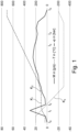
- FIG. 1 A diagram is shown to explain the standard filling process at a hydrogen filling station.
- Curve K 1 is the pressure in or on the receiving tank.
- K 2 shows the mass flow through a connecting hose between the delivery point and the receiving tank.
- K 3 shows the temperature in the tank hose during the refueling process.
- Fig. 1 The time during the refueling process is entered on the abscissa.
- the mass flow in g/s for curve K 3 is shown on the left ordinate.
- the pressure in bar for curve K 1 and the temperature in °C for curve K 3 are shown with the same resolution.
- the refueling hose is connected between the hydrogen delivery unit, i.e. the fuel pump and the receiving tank.
- a high pressure pulse is introduced into the closed hose system via the gas station system, which, however, only lasts a short time. It is then checked whether the pressure can be maintained or not. This ensures and checks whether the connection is fluid-tight. Refueling then begins at time t 2 .
- hydrogen filling stations in Europe have three different tanks: a low-pressure tank up to around 200 bar, a medium-pressure tank up to around 600 bar and a high-pressure tank with a filling between 700 bar and 800 bar.
- the gas station determines that the filling from the low-pressure tank, which was initially started, is no longer running sufficiently quickly and switches to the medium-pressure tank.
- the same determination takes place for the medium-pressure tank, so that a switch is made to the high-pressure tank.
- the refueling process is completed because the maximum permitted pressure is present in the vehicle's tank.
- Further embodiments of hydrogen filling stations use cryogenic liquid hydrogen, which is evaporated and compressed in a similar process and used as highly compressed hydrogen for vehicle refueling.
- FIG. 2 A hydrogen delivery point 60, for example in the form of a gas station, is initially provided on the left side. This has a hydrogen delivery unit 61, on which a connecting piece 62 is provided. On the right side of the figure, a motor vehicle 70 is shown, in which a receiving tank 71 is arranged, which in turn has a connecting piece 72.
- a direct fluid-tight connection would be established with a delivery hose between the hydrogen delivery point 61 or the connecting piece 62 and the receiving tank 61 or its connecting piece 72.
- a measuring system 1 is interposed.
- the measuring system 1 consists of two main components. On the one hand a measuring unit 10 and on the other hand a display unit 20.
- a flow meter 12 is provided in the measuring unit 10 and has a corresponding control and evaluation unit 19. Furthermore, two connecting pieces 11, 16 are provided. A fluid-tight connection is provided between the two connecting pieces 11, 16 and is passed through the flow meter 12. A temperature sensor 13 and a pressure sensor 14 are also arranged at this connection.
- the display unit 20 has a data logger 22 and a measurement display 24. Both the data logger 22 and the measurement display 24 are in communication connection with the control and evaluation unit 19 as well as the temperature sensor 13 and the pressure sensor 14. These connections are in Fig. 1 only hinted at.
- a fluid-tight connection is established between the hydrogen delivery unit 61 or its connection 62 and the connecting piece 11 of the measuring unit 10 as well as the connecting piece 16 of the measuring unit 10 and the connecting piece 72 of the receiving tank 71.
- the hydrogen Since the hydrogen is highly compressed and is initially filled into an empty tank 71, it heats up again in the receiving tank 71. However, since the tanks in the 70 vehicle in particular are only permitted up to a temperature of approx. + 80°C, this heating must largely be reduced or prevented. For this reason, the hydrogen delivered from the hydrogen delivery point 60 via the hydrogen delivery unit 61 is delivered cooled. This results in a temperature in the range from -10°C to -30°C in the fluid-tight connection during the release of the hydrogen.
- a receptacle 15 is provided in the measuring unit 10, which is accessible from the outside.
- an external cooling material 30, for example dry ice is provided in simplified form.
- the receiving device 15 is constructed in such a way that it ends in the area of the flow meter 12 and, for example, has a common wall 17 with the flow meter 12. This creates thermal contact so that the flow meter 12 can be cooled.
- cooling material 30 For example, if dry ice is used as the cooling material 30, it offers the advantage that it is relatively easy to obtain and inexpensive. It can also be used in the explosion-proof area of a gas station because it is inert.
- an infrared connection which can be wired, is provided in accordance with the standards. Information about the refueling status and the like is exchanged between the receiving tank 71 and the hydrogen delivery unit 61 via this infrared connection.
- the infrared connection can be routed past the measuring system 1, as shown with the infrared connection 41.
- the measuring system 1 does not record any information from the infrared channel.
- the measuring system 1 can be actively interposed.
- Two infrared connections 42 are provided for this purpose, which are in Fig. 2 are also marked.
- the advantage of the system according to the invention is that it allows a highly accurate measurement to be carried out, which, however, does not require significantly more time than a standard refueling process.
Landscapes
- Engineering & Computer Science (AREA)
- Physics & Mathematics (AREA)
- Fluid Mechanics (AREA)
- General Physics & Mathematics (AREA)
- Mechanical Engineering (AREA)
- General Engineering & Computer Science (AREA)
- Filling Or Discharging Of Gas Storage Vessels (AREA)
- Vehicle Cleaning, Maintenance, Repair, Refitting, And Outriggers (AREA)
- Measuring Volume Flow (AREA)
- Fuel Cell (AREA)
Description
- Die Erfindung betrifft ein Messsystem zum Ermitteln einer abgegebenen Wasserstoffmenge einer Wasserstoffabgabestelle von einer dort vorhandenen Wasserstoffabgabeeinheit an einen Aufnahmetank. Hierfür ist in dem Messsystem eine Messeinheit vorgesehen.
- Bei der Wasserstoffabgabestelle kann es sich beispielsweise um eine Wasserstofftankstelle handeln, wobei die Wasserstoffabgabeeinheit die entsprechende Zapfstelle oder -säule ist.
- Die Erfindung betrifft weiter ein Verfahren zum Ermitteln der abgegebenen Wasserstoffmenge einer Wasserstoffabgabestelle, insbesondere einer Wasserstofftankstelle, mit einer Wasserstoffabgabeeinheit an einen Aufnahmetank.
- Neben der Elektrifizierung von Fahrzeugen stellt die Verwendung von Wasserstoff als Energielieferant eine weitere Möglichkeit dar, Mobilität umweltfreundlicher zu realisieren. Das Verwenden von Wasserstoff hat gegenüber der Verwendung von Elektrizität zur Zeit den Vorteil, dass die Tankvorgänge im Vergleich zum Laden einer Batterie deutlich schneller vorgenommen werden können und die Reichweiten der Brennstoffzellen-Fahrzeuge deutlich größer ist, als der von rein batterieelektrischen Fahrzeugen. Auch besteht die Problematik der Entsorgung der oft hochgiftigen Batterien nicht.
- Ein Wasserstoff-Tankstellennetz besteht allerdings noch nicht beziehungsweise noch nicht in ausreichend dichter Form. Beim Betreiben und Bauen einer WasserstoffTankstelle sind verschiedene nationalen Vorgaben zu beachten. Beispielsweise ist es in Deutschland notwendig eichrechtlich zu überprüfen, ob die an der Tankstelle angegebenen Abgabemenge, also die getankte und somit abgegebene Menge Wasserstoff, mit der wirklich abgegebenen Menge übereinstimmt.
- Gängige Tankvorgänge werden mit verschiedenen Druckbereichen von etwa 20 bar bis ca. 700 bar durchgeführt. Derart hohe Drücke sind vorgesehen, um den Tankvorgang möglichst schnell durchzuführen, so dass ähnliche Tankzeiten wie bei flüssigen Kraftstoffen, wie Benzin oder Diesel, erreicht werden können.
- Dies hat jedoch die Folge, dass sich der in einem Tank eingebrachte Wasserstoff beim Komprimieren erwärmt. Konstruktionsbedingt sind derartige Tanks bis maximal 90°C zu belasten. Um nicht unnötigerweise den Tankvorgang zu früh abbrechen zu müssen und schnell zu betanken, wird der Wasserstoff gekühlt, so dass er eine Temperatur zwischen - 20°C bis zu - 40°C aufweist.
- Für die notwendigen Eichvorgänge sind zurzeit im Wesentlichen gravimetrische Systeme bekannt.
- Hierbei ist ein Aufnahmetank auf einem Anhänger montiert und weist eine integrierte, hochgenaue Waage auf. Dieser Tank wird mittels der Wasserstoffabgabeeinheit betankt. Anschließend wird die Gewichtszunahme, die im Bereich von 1kg bis 4kg liegt, hochgenau festgestellt. Diese Größe wird mit der von der Tankstelle angegebenen Messgröße verglichen, um so eine Eichung durchzuführen.
- Problematisch an diesen Systemen ist jedoch, dass sie äußerst sensibel und fehleranfällig sind. So hat der Tank mit Aufbau meist ein Gewicht von ca. 400kg, wobei lediglich ein Bruchteil des Gewichts zugetankt wird - 1kg bis 4kg Wasserstoff. Aufgrund der notwendigen hoch genauen Auflösung der Waage ist jedoch der Anhänger, auf welchem sich der Tank befindet, sehr anfällig auf Umwelteinflüsse. So ist bereits die Winddrucklast auf den Anhänger auf Waage sichtbar. Somit kann die Messung idealerweise nur bei gutem Wetter und in den Sommermonaten durchgeführt werden.
- Ein weiteres Problem ist in der Leerung des Tanks zu sehen. Um verlässliche Messungen durchzuführen, ist es eichrechtlich notwendig, mindestens drei kontinuierliche Messungen vorzulegen. Jedoch kann der Tank nur relativ langsam entleert werden, da er anderenfalls durch eine schnelle Expansion des Wasserstoffes beschädigt werden könnte und in seiner Struktur Schäden entstehen könnten. Auch kühlt der sich expandierende Wasserstoff beim Abblasen stark ab, so dass Kondensat auf dem Tank entsteht. Das Kondensat wiederum führt zu erheblichen Messabweichungen.
- Dazu wird zur Zeit der abgelassene Wasserstoff in die Umwelt abgeblasen, ohne dass er genutzt wird. Hierzu muss extra ein Kamin, mindestens 20 Meter von der Tankstelle entfernt, aufgebaut werden, um ein sicheres Abblasen des Wasserstoffes zu gewährleisten.
- All dies hat zur Folge, dass eine entsprechende Eichkampagne 3 bis 4 Tage dauert und solange die Tankstelle blockiert ist. Hierbei ist zu berücksichtigen, dass es eine derartige Eichung alle 1 bis 2 Jahre durchgeführt werden soll.
- Aus der
US 2020/173607 A1 ist ein Systeme bekannt, das zur Abgabe von Wasserstoff an Verbraucher wie ein Kfz geeignet ist, bei der Durchfluss bestimmt wird. - Der Erfindung liegt daher die Aufgabe zugrunde, ein effizientes Messsystem und Messverfahren, mit denen die abgegebene Wasserstoffmenge von einer Wasserstoffabgabeeinheit an einen Aufnahmetank gemessen wird, bereitzustellen.
- Diese Aufgabe wird erfindungsgemäß durch ein System mit den Merkmalen des Anspruchs 1 sowie ein Messverfahren mit den Merkmalen des Anspruchs 13 gelöst.
- Weitere vorteilhafte Ausführungsformen sind in den abhängigen Ansprüchen, der Beschreibung sowie in den Figuren und deren Beschreibung angegeben.
- Entsprechend der Erfindung ist vorgesehen, dass die Messeinheit einen Durchflussmesser aufweist, der zwischen der Wasserstoffabgabeeinheit und dem Aufnahmetank anordenbar ist. Ferner ist das Messsystem ausgebildet, eine fluiddichte Verbindung zwischen der Wasserstoffabgabeeinheit und dem Aufnahmetank aufzubauen und den von der Wasserstoffabgabeeinheit abgegebenen Wasserstoff durch den Durchflussmesser zum Aufnahmetank zu leiten. Weiter ist vorgesehen, dass der Durchflussmesser eine aktive Kühlung aufweist.
- Ein Grundgedanke der Erfindung kann darin gesehen werden, dass es mit entsprechend weiteren Mitteln möglich ist, die abgegebene Wasserstoffmenge mit einem Durchflussmesser hochgenau zu ermitteln. Hierbei ist zu berücksichtigen, dass der Durchflussmesser vor der Abgabe meist Raumtemperatur beziehungsweise Außentemperatur hat. Dies heißt, die Temperaturen können sich zwischen +5°C und +40°C belaufen. Wie bereits erläutert, hat der gasförmige hochkomprimierte Wasserstoff eine Temperatur von bis zu - 40°C. Dies hat zur Folge, dass bei den erforderlichen hochgenauen Durchflussmessern bei dem Durchführen von Messungen ein hoher Nullpunktdrift vorliegen würde, so dass die eichrechtlich erforderte Genauigkeit der Messung nicht erreicht werden könnte.
- Entsprechend der Erfindung wurde jedoch erkannt, dass dieses Problem umgangen werden kann, sofern der Durchflussmesser aktiv gekühlt wird. Anders ausgedrückt, ist eine aktive Kühlung vorgesehen, die den Durchflussmesser vor einer Messung bereits auf Temperaturen im Bereich zwischen - 30°C und - 50°C kühlt, so dass beim Durchleiten des hochkomprimierten und gekühlten Wasserstoffs keine oder im Wesentlichen keine Änderung der Temperatur im Durchflussmesser mehr auftritt.
- Mittels der Erfindung ist es so möglich, eine Messkampagne in deutlich kürzerer Zeit und relativ unabhängig von den Außentemperaturen durchzuführen.
- Entsprechend der Erfindung ist es bevorzugt, wenn die aktive Kühlung als externe Kühlung des Durchflussmessers vorgesehen ist. Dies kann insbesondre auch bedeutet, dass die aktive Kühlung kein Teil des Durchflussmessers selbst ist, sondern als weiteres Bauteil oder Aggregat hinzugefügt werden kann.
- Grundsätzlich sind verschiedene Möglichkeiten der aktiven Kühlung denkbar. So kann beispielsweise ein Peltier-Element oder auch eine klassische Kompressorkühlung hierfür eingesetzt werden. Es ist jedoch bevorzugt, wenn die aktive Kühlung mittels eines externen Kühlmaterials durchgeführt wird. Hierfür eignet sich insbesondere Trockeneis.
- Eine Wasserstofftankstelle gilt als explosionsgefährdete Zone und wird als Ex-Zone 1 eingeordnet. Dies bedeutet, dass alle dort vorhandenen Geräte entsprechend explosionsgeschützt ausgebildet sein müssen. Hierbei zeigt sich insbesondere der Vorteil eines externen, insbesondere energieversorgungslosen, Kühlmaterials, bei dem es sich beispielsweise um Trockeneis handeln kann.
- Trockeneis ist nicht brennbar und weist eine Temperatur von ca. -78°C auf. Es ist grundsätzlich kostengünstig zu beschaffen und, abgesehen von den kalten Temperaturen, auch einfach zu handhaben. Somit ergeben sich keine Probleme bezüglich der Ex-Zone beziehungsweise dem notwendigen Explosionsschutz. Bei Trockeneis handelt es sich um festes Kohlenstoffdioxid (CO2). Es hat auch den Vorteil, dass es bei Außentemperatur gasförmig ist, also verdampft. Generell sind aber auch andere Kältespeicher geeignet.
- Bevorzugt ist es, wenn eine Aufnahmeeinrichtung mit thermischem Kontakt zum Durchflussmesser in der Messeinheit ausgebildet ist. So ist es möglich, in die Aufnahmeeinrichtung das externe Kühlmaterial einzubringen und den Durchflussmesser möglichst effizient und einfach zu kühlen. Die Aufnahmeeinrichtung kann beispielsweise wannenartig ausgebildet sein.
- Hierfür kann die Aufnahmeeinrichtung beispielsweise als von außen zugänglicher Hohlraum ausgebildet sein. Dies kann in Form einer einfachen Kammer realisiert sein, die eine entsprechende Klappe aufweist, so dass sie zugänglich ist. Durch einen Verschluss der Klappe kann sichergestellt werden, dass während des Durchführens einer Messung möglichst wenig Umwelteinflüsse über diese Kammer auf den Durchflussmesser einwirken.
- Die thermische Kopplung zwischen der Aufnahmeeinrichtung und dem Durchflussmesser kann auf verschiedene Arten realisiert sein. Eine Möglichkeit ist es, hierbei eine Wand der Aufnahmeeinrichtung durch einen Teil des Körpers des Durchflussmessers auszubilden. Es bietet sich an, das Gehäuse oder den Körper des Durchflussmessers in Edelstahl und massiv auszuführen, so dass eine gute Wärmeübertragung stattfindet, bzw. der Durchflussmesser gut gekühlt wird.
- Eine höhere Masse dieses Gehäuses beziehungsweise des Körpers des Durchflussmessers erfordert zwar eine längere und stärkere Kühlung, bietet jedoch den Vorteil, dass Temperaturschwankungen im Prozess der Messung weniger stark auftreten.
- Als Durchflussmesser können verschiedene Durchflussmesser eingesetzt werden. Beispielhaft hierfür ist ein Coriolis-Durchflussmesser, ein Ultraschalldurchflussmesser oder ein Durchflussmesser mittels kritischer Düsen. Selbstverständlich können auch andere Arten von Durchflussmessern, die geeignet sind, Fluide, insbesondere Gase, zu messen, verwendet werden.
- Vorteilhaft ist es, wenn eine Verbindung zum Übertragen bidirektionaler Infrarotsignale zwischen der Wasserstoffabgabeeinheit und dem Aufnahmetank vorgesehen ist. Hierbei kann die Verbindung als Bypass um die Messeinrichtung, aber auch durch die Messeinrichtung selbst geführt werden.
- Bei in Europa üblichen Wasserstofftankstellen sind parallel innerhalb beziehungsweise am Tankschlauch Verbindungsmittel für eine Infrarotverbindung zwischen der Wasserstoffabgabeeinheit, also der Zapfsäule, und dem Aufnahmetank, beispielsweise in einem Auto, vorgesehen. Diese Infrarotverbindung, die meist kabelgebunden ist, dient zur bidirektionalen Kommunikation zwischen der Wasserstoffabgabeeinheit und dem Aufnahmetank. Wie im Folgenden noch genauer erläutert, werden hierbei die Tankparameter ausgehandelt beziehungsweise der Tankvorgang gesteuert. Die Verbindung kann aber auch drahtlos sein.
- Durch das Vorsehen der bidirektionalen Infrarotverbindung während des Messvorgangs kann ein sicheres Tanken ermöglicht werden. Eine Möglichkeit ist, die Verbindung für die bidirektionalen Infrarotsignale an der Messeinheit vorbeizuführen. Anders ausgedrückt kann der Tankschlauch von der Zapfsäule an die Messeinheit angeschlossen werden, wobei die kabelgebundene Infrarotverbindung mit einem weiteren Kabel separat an der Messeinheit vorbei direkt zum Aufnahmetank, der sich in einem Kfz befinden kann, geleitet wird. Von der Messeinheit wiederum wird mit einem zweiten Betankungsschlauch eine Verbindung zu dem Tank hergestellt. So können sowohl die Infrarotsignale zwischen dem Aufnahmetank und der Wasserstoffabgabeeinheit übertragen werden als auch der Wasserstoff in den Aufnahmetank transferiert werden.
- In einer anderen Ausführungsform kann die Infrarotsignalverbindung durch die Messeinheit geführt werden. Hierzu wird der Tankschlauch der Wasserstoffabgabeeinheit direkt an die Messeinheit angeschlossen. Diese leitet die Infrarotsignale wiederum weiter. Dafür kann ein entsprechender Tankschlauch zwischen der Messeinheit und dem Aufnahmetank angeschlossen werden, worüber sowohl der Wasserstoff getankt werden kann als auch die Infrarotsignale weitergeleitet werden können. Selbstverständlich sind auch Lösungen möglich, in denen die Infrarotsignale mittels einer zwischengeschalteten Funkverbindung übertragen werden.
- Vorteilhafterweise weist die Messeinheit des Messsystems den Durchflussmesser sowie eine Steuer- und Auswerteeinheit auf. Die Steuer- und Auswerteeinheit dient im Wesentlichen zur Ansteuerung und Auswertung der Daten des Durchflussmessers. Dies ermöglicht eine kurze Leitungsverbindung, so dass die hochgenaue Messung weiter unterstützt wird.
- Zusätzlich kann eine separate Anzeigeeinheit vorgesehen sein, welche mindestens einen Datenlogger und eine Messeinheit aufweist. Diese Anzeigeeinheit kann in Kommunikationsverbindung mit der Messeinheit stehen. Grundsätzlich ist es aber auch möglich, die Anzeigeeinheit und die Messeinheit integriert auszuführen.
- Die in der Anzeigeeinheit vorgesehene Messanzeige dient zur Ausgabe der gemessenen Ergebnisse. Um eichrechtlich ausreichende Voraussetzungen zu schaffen, kann zusätzlich der Datenlogger vorgesehen sein, der alle Daten mitloggt.
- Außerdem ist es möglich, in der Anzeigeeinheit weitere Auswerteelektronik vorzusehen, beispielsweise eine Datenschnittstelle, um die Daten aus dem Datenlogger herunterzuladen oder auch Mittel für eine Datenübertragung per Funk an eine übergeordnete Stelle.
- Ferner betrifft die Erfindung ein Verfahren zum Ermitteln der abgegebenen Wasserstoffmenge einer Wasserstoffabgabestelle, insbesondere einer Wasserstofftankstelle, mit einer Wasserstoffabgabeeinheit an einen Aufnahmetank. Hierbei ist entsprechend der Erfindung vorgesehen, dass das zuvor beschriebene Messsystem verwendet wird. Zum Durchführen des Verfahrens wird eine fluiddichte Verbindung zwischen der Wasserstoffabgabeeinheit und der Messeinheit sowie zwischen der Messeinheit und dem Aufnahmetank aufgebaut. Hierfür kann der normale Abgabeschlauch beziehungsweise der Tankschlauch der Wasserstoffabgabeeinheit an die Messeinheit angeschlossen werden, die eine entsprechende Schnittstelle, bzw. Kupplung aufweist.
- Zusätzlich wird vom Messsystem zum Aufnahmetank ein ähnlich ausgebildeter Betankungsschlauch angeschlossen. Innerhalb der Messeinheit ist ebenfalls eine fluiddichte Verbindung von dem Anschluss für die Wasserstoffabgabeeinheit zu dem Anschluss für den Aufnahmetank vorgesehen.
- Anschließend wird über die fluiddichte Verbindung Wasserstoff von der Wasserstoffabgabeeinheit über den Durchflussmesser des Messsystems zum Aufnahmetank transferiert. Hierbei ist der Durchflussmesser des Messsystems in der Verbindung zwischen dem Anschluss für die Wasserstoffabgabeeinheit und dem Aufnahmetank angeordnet.
- Fluid im Sinne der Erfindung kann sowohl ein Gas wie auch ein Flüssigkeit sein, obwohl im Folgenden das Beispiel von Wasserstoff als Gas näher erläutert wird.
- Während des Durchflusses des Wasserstoffs durch den Durchflussmesser bei der Abgabe des Wasserstoffs von der Wasserstoffabgabeeinheit an den Aufnahmetank wird die Menge, welche durch den Durchflussmesser fließt, ermittelt. Um die zuvor beschriebene Temperaturdrift und die damit verbundenen Genauigkeitsprobleme auszuschließen, wird der Durchflussmesser vor Beginn des Transfers des Wasserstoffs von der Wasserstoffabgabeeinheit an den Aufnahmetank aktiv gekühlt. Im Rahmen der Erfindung bedeutet vor Beginn des Transfers, dass die Kühlung derart rechtzeitig begonnen wird, dass der Durchflussmesser sich auf seiner Betriebstemperatur befindet, bevor mit dem Betankungsvorgang begonnen wird.
- Vorteilhaft ist es, wenn der Durchflussmesser mit einem in den Aufnahmeraum eingebrachten Kühlmaterial, insbesondere Trockeneis, gekühlt wird. Trockeneis bietet, wie bereits beschrieben, ein relativ kostengünstiges und einfach zu handhabendes Material, welches auch unproblematisch in explosionsgeschützten Bereichen verwendet werden kann.
- Die Erfindung wurde hier insbesondere in Bezug auf Wasserstoff beschrieben. Sie kann aber auch für zum hochgenauen Ermitteln einer abgegebenen Menge einer beliebigen anderen Fluides, insbesondere wenn es gekühlt transferiert wird, verwendet werden.
- Die Erfindung wird nachfolgend anhand eines Ausführungsbeispiels sowie schematischen Zeichnungen näher erläutert. In diesen Zeichnungen zeigen:
- Fig. 1
- ein Diagramm zur Erläuterung eines typischen Befüllvorgangs an einer Wasserstofftankstelle; und
- Fig. 2
- eine vereinfachte Darstellung des erfindungsgemäßen Messsystems.
- In
Fig. 1 ist ein Diagramm zur Erläuterung des standardmäßigen Befüllvorgangs an einer Wasserstofftankstelle dargestellt. - Hierbei sind drei unterschiedliche Kurven K1, K2 und K3 über die Zeit gezeigt. Bei der Kurve K1 handelt es sich um den im beziehungsweise am Aufnahmetank anliegenden Druck. K2 zeigt den Massenstrom durch einen Verbindungsschlauch zwischen der Abgabestelle und dem Aufnahmetank. K3 verdeutlicht die Temperatur im Tankschlauch während des Tankvorgangs.
- In
Fig. 1 ist auf der Abszisse die Zeit während des Betankungsvorgangs eingetragen. Auf der linken Ordinate ist der Massenstrom in g/s für Kurve K3 gezeigt. Auf der rechten Ordinate ist mit derselben Auflösung der Druck in bar für Kurve K1 sowie die Temperatur in °C für Kurve K3 dargestellt. - Im Folgenden wird der Betankungsvorgang grundsätzlich erläutert: Zum Zeitpunkt t0 wird der Betankungsschlauch zwischen der Wasserstoffabgabeeinheit, also der Zapfsäule und dem Aufnahmetank angeschlossen. Zum Zeitpunkt t1 wird über das System der Tankstelle ein hoher Druckimpuls in das geschlossene Schlauchsystem eingeleitet, der jedoch nur eine kurze Dauer hat. Anschließend wird geprüft, ob der Druck aufrechterhalten werden kann oder nicht. Hiermit wird sichergestellt und überprüft, ob die Verbindung fluiddicht ist. Anschließend wird zum Zeitpunkt t2 mit der Betankung begonnen.
- Standardmäßig haben Wasserstofftankstellen in Europa drei verschiedene Tanks: einen Niederdrucktank bis etwa 200 bar, einen Mitteldrucktank bis etwa 600 bar und einen Hochdrucktank mit einer Füllung zwischen 700 bar und 800 bar. Zum Zeitpunkt t3 wird durch die Tankstelle ermittelt, dass die Füllung aus dem Niederdrucktank, mit dem zuerst begonnen wurde, nicht mehr ausreichend schnell verläuft und auf den Mitteldrucktank umgeschaltet. Zum Zeitpunkt t4 findet dieselbe Ermittlung beim Mitteldrucktank statt, so dass auf den Hochdrucktank umgeschaltet wird. Zum Zeitpunkt t5 ist der Tankvorgang beendet, da der maximale erlaubte Druck im Tank des Fahrzeugs vorhanden ist. Weitere Ausführungsformen von Wasserstofftankstellen nutzen tiefkalten flüssigen Wasserstoff, der verdampft und komprimiert in einem ähnlichen Prozess als hochverdichteter Wasserstoff zur Fahrzeugbetankung genutzt wird.
- Mittels des erfindungsgemäßen Messsystems, welches im Folgenden näher erläutert wird und in
Fig. 2 schematisch dargestellt ist, kann der Massenstrom während des Betankungsvorgangs hochgenau ermittelt werden. - In
Fig. 2 ist zunächst auf der linken Seite eine Wasserstoffabgabestelle 60, beispielsweise in Form einer Tankstelle, vorgesehen. Diese weist eine Wasserstoffabgabeeinheit 61 auf, an der ein Anschlussstutzen 62 vorgesehen ist. Auf der rechten Seite der Figur ist ein Kfz 70 dargestellt, in dem ein Aufnahmetank 71 angeordnet ist, der wiederum einen Anschlussstutzen 72 aufweist. - Im Normalbetrieb würde eine direkte fluiddichte Verbindung mit einem Abgabeschlauch zwischen der Wasserstoffabgabestelle 61 beziehungsweise dem Anschlussstutzen 62 und dem Aufnahmetank 61 beziehungsweise dessen Anschlussstutzen 72 aufgebaut. Um jedoch eine Eichung der durch die Wasserstoffabgabeeinheit 61 abgegebene Wasserstoffmenge oder ein zusätzliches Überprüfen vorzusehen, wird ein erfindungsgemäßen Messsystem 1 dazwischengeschaltet.
- Das erfindungsgemäße Messsystem 1 besteht aus zwei Hauptkomponenten. Zum einen eine Messeinheit 10 zum anderen eine Anzeigeeinheit 20.
- In der Messeinheit 10 ist ein Durchflussmesser 12 vorgesehen, welcher eine entsprechende Steuer- und Auswerteeinheit 19 aufweist. Ferner sind zwei Anschlussstutzen 11, 16 vorgesehen. Zwischen den beiden Anschlussstutzen 11, 16 ist eine fluiddichte Verbindung vorgesehen, die durch den Durchflussmesser 12 geleitet ist. An dieser Verbindung sind zusätzlich ein Temperatursensor 13 und ein Drucksensor 14 angeordnet. Die Anzeigeeinheit 20 weist in der exemplarisch ausgeführten Form einen Datenlogger 22 sowie eine Messanzeige 24 auf. Sowohl der Datenlogger 22 als auch die Messanzeige 24 stehen in Kommunikationsverbindung mit der Steuer- und Auswerteeinheit 19 sowie dem Temperatursensor 13 und dem Drucksensor 14. Diese Verbindungen sind in
Fig. 1 nur angedeutet. - Um eine Messung der abgegebenen Menge durchzuführen, wird entsprechend der Erfindung eine fluiddichte Verbindung zwischen der Wasserstoffabgabeeinheit 61 beziehungsweise deren Anschluss 62 und dem Anschlussstutzen 11 der Messeinheit 10 sowie dem Anschlussstutzen 16 der Messeinheit 10 und dem Anschlussstutzen 72 des Aufnahmetanks 71 hergestellt. Nun kann über die Wasserstoffabgabeeinheit 61 Wasserstoff in den Aufnahmetank 71 fließen. Hierzu wird das zuvor in Bezug auf
Fig. 1 beschriebene Verfahren angewendet. - Da der Wasserstoff hochkomprimiert ist und zunächst in einen leeren Tank 71 gefüllt wird, erwärmt er sich in dem Aufnahmetank 71 wieder. Da die Tanks gerade im Kfz 70 jedoch nur bis zu einer Temperatur von ca. + 80°C zugelassen sind, muss diese Erwärmung größtenteils vermindert beziehungsweise verhindert werden. Aus diesem Grund wird der von der Wasserstoffabgabestelle 60 über die Wasserstoffabgabeeinheit 61 abgegebene Wasserstoff gekühlt geliefert. Dies führt dazu, dass in der fluiddichten Verbindung während der Abgabe des Wasserstoffs eine Temperatur im Bereich von - 10°C bis - 30°C vorliegt.
- Dies führt jedoch zu Problemen bei der Messgenauigkeit des Durchflussmessers 12, da hier ein sehr großer Temperaturbereich abgedeckt werden muss. So tritt ein Nullpunktdrift auf, der für eine eichtechnische Messung nicht mehr akzeptabel ist.
- Aus diesem Grund wird entsprechend der Erfindung vorgeschlagen, den Durchflussmesser 12 aktiv zu kühlen. Hierfür ist entsprechend der Erfindung in der Messeinheit 10 eine Aufnahme 15 vorgesehen, die von außen zugänglich ist. In
Fig. 1 ist in dieser Aufnahme 15 vereinfacht ein externes Kühlmaterial 30, beispielsweise Trockeneis, vorgesehen. Die Aufnahmeeinrichtung 15 ist so konstruiert, dass sie im Bereich des Durchflussmessers 12 endet und beispielsweise eine gemeinsame Wand 17 mit dem Durchflussmesser 12 aufweist. So entsteht ein thermischer Kontakt, so dass der Durchflussmesser 12 gekühlt werden kann. - Wird beispielsweise als Kühlmaterial 30 Trockeneis verwendet, so bietet es den Vorteil, dass es relativ einfach zu beschaffen und kostengünstig ist. Auch in dem explosionsgeschützten Bereich einer Tankstelle kann es verwendet werden, da es inert ist.
- Die während einer derartigen Messung ermittelten Daten, zum einen der Steuer- und Auswerteeinheit 16 zum Durchfluss und zum anderen der fakultativ vorgesehenen Daten des Temperatursensors 13 und des Drucksensors 14, werden an die Anzeigeeinheit 20 weitergeleitet und dort sowohl in einem Datenlogger 22 gespeichert als auch an einer entsprechenden Messanzeige 24 dargestellt zu werden.
- Um eine Kommunikation zwischen der Wasserstoffabgabe 61 und dem Aufnahmetank 71 zu ermöglichen, ist entsprechend der Standards eine Infrarotverbindung, welche kabelgebunden ausgeführt sein kann, vorgesehen. Über diese Infrarotverbindung werden zwischen dem Aufnahmetank 71 und der Wasserstoffabgabeeinheit 61 Informationen zum Betankungszustand und dergleichen ausgetauscht.
- Um diese Kommunikation weiterhin zu erlauben, sind entsprechend der Erfindung zwei Möglichkeiten vorgeschlagen. Diese sind beide in
Fig. 2 dargestellt, wobei normalerweise nicht beide Möglichkeiten gleichzeitig verwendet werden. - Zum einen kann die Infrarotverbindung an dem Messsystem 1 vorbeigeleitet werden, wie es mit der Infrarotverbindung 41 gezeigt ist. Hierbei nimmt das Messsystem 1 keine Informationen aus dem Infrarotkanal auf. Zum anderen kann das Messsystem 1 aktiv zwischengeschaltet werden. Hierfür sind zwei Infrarotverbindungen 42 vorgesehen, die in
Fig. 2 ebenfalls eingezeichnet sind. - Dies führt dazu, dass die Informationen durch die Messeinheit 10 verlaufen und dort unter Umständen mitgelesen werden können beziehungsweise auch zusätzlich ausgewertet werden können.
- Der Vorteil des erfindungsgemäßen Systems besteht darin, dass hierdurch eine hochgenaue Messung durchgeführt werden kann, die jedoch nicht deutlich mehr Zeit benötigt als ein Standardtankvorgang.
- Eichrechtlich sind mindestens zwei bis vier Betankungsvorgänge vorgesehen, die im erfindungsgemäßen System genau wie eine Normalbetankung an der Tankstelle ohne Weiteres durchgeführt werden können. Dies bringt einen erheblichen Zeitvorteil im Gegensatz zu bekannten Systemen.
- So ist es mit dem erfindungsgemäßen Messsystem und der erfindungsgemäßen Verfahren möglich, eine Eichtestmessung einer Wasserstofftankstelle effizient und schnell durchzuführen.
Claims (14)
- Messsystem (1) zum Ermitteln einer abgegebenen Wasserstoffmenge einer Wasserstoffabgabestelle (60), insbesondere einer Wasserstofftankstelle, von einer dort vorhandenen Wasserstoffabgabeeinheit (61) in Form einer Zapfsäule an einen Aufnahmetank (71),mit einer Messeinheit (10),wobei die Messeinheit (10) einen Durchflussmesser (12) aufweist, der zwischen der Wasserstoffabgabeeinheit (61) in Form der Zapfsäule und dem Aufnahmetank (71) anordenbar ist,wobei das Messsystem (1) ausgebildet ist, eine fluiddichte Verbindung zwischen der Wasserstoffabgabeeinheit (61) in Form der Zapfsäule und dem Aufnahmetank (71) aufzubauen, wobei eine fluiddichte Verbindung von der der Wasserstoffabgabeeinheit (61) in Form einer Zapfsäule zur Messeinheit (10) und eine fluiddichte Verbindung von der Messeinheit (10) zum Aufnahmetank (71) aufbaubar ist,wobei die Messeinheit ausgebildet ist von der Wasserstoffabgabeeinheit (61) in Form der Zapfsäule abgegebenen Wasserstoff durch den Durchflussmesser (12) der Messeinheit zum Aufnahmetank (71) zuleitet unddadurch gekennzeichnet, dassder Durchflussmesser (12) eine aktive Kühlung aufweist, welche ausgebildet ist, den Durchflussmesser (12) vor dem Beginn des Transfers des Wasserstoffes derart abzukühlen, dass beim Transfer im Wesentlichen keine Änderung der Temperatur im Durchflussmesser mehr auftritt.
- Messsystem (1) nach Anspruch 1,
dadurch gekennzeichnet,
dass die aktive Kühlung eine externe Kühlung ist. - Messsystem (1) nach Anspruch 1 oder 2,
dadurch gekennzeichnet,
dass die aktive Kühlung mittels eines externen Kühlmaterials (30), insbesondere Trockeneis, realisiert ist. - Messsystem (1) nach Anspruch 1 bis 3,
dadurch gekennzeichnet,
dass eine Aufnahmeeinrichtung (15) mit thermischem Kontakt zum Durchflussmesser (12) in der Messeinheit (10) ausgebildet ist. - Messsystem (1) nach Anspruch 4,
dadurch gekennzeichnet,
dass die Aufnahmeeinrichtung (15) als von außen zugänglicher Hohlraum ausgebildet ist. - Messsystem (1) nach Anspruch 4 oder 5,
dadurch gekennzeichnet,
dass eine Wand der Aufnahmeeinrichtung (15) durch einen Körper des Durchflussmessers (12) ausgebildet ist. - Messsystem (1) nach einem der Ansprüche 1 bis 6,
dadurch gekennzeichnet,
dass der Durchflussmesser (12) als ein Coriolis-Durchflussmesser, ein Ultraschall-Durchflussmesser oder ein Durchflussmesser mittels kritischer Düsen ausgeführt ist. - Messsystem (1) nach einem der Ansprüche 1 bis 7,
dadurch gekennzeichnet,
dass eine Verbindung (41, 42) zum Übertragen kabelgebundener bidirektionaler Infrarotsignale zwischen der Wasserstoffabgabeeinheit (61) und dem Aufnahmetank (71) vorgesehen ist. - Messsystem (1) nach Anspruch 8,
dadurch gekennzeichnet,
dass die Verbindung (42) um die Messeinheit (10) geführt ist. - Messsystem (1) nach Anspruch 8,
dadurch gekennzeichnet,
dass die Verbindung (42) durch die Messeinheit (10) geführt ist. - Messsystem (1) nach einem der Ansprüche 1 bis 10,
dadurch gekennzeichnet,
dass die Messeinheit (10) den Durchflussmesser (12) und eine Steuer- und Auswerteeinheit (19) aufweist. - Messsystem (1) nach einem der Ansprüche 1 bis 11,
dadurch gekennzeichnet,dass eine Anzeigeeinheit (20) vorgesehen ist, die mindestens einen Datenlogger (22) und eine Messanzeige (14) aufweist unddass die Anzeigeeinheit (20) in Kommunikationsverbindung mit der Messeinheit (10) steht. - Verfahren zum Ermitteln der abgegebenen Wasserstoffmenge einer Wasserstoffabgabestelle (60), insbesondere einer Wasserstofftankstelle, mit einer Wasserstoffabgabeeinheit (61) in Form einer Zapfsäule an einen Aufnahmetank (71),wobei ein Messsystem mit einer Messeinheit (10) verwendet wird, wobei die Messeinheit (10) einen zwischen der Wasserstoffabgabeeinheit (61) in Form der Zapfsäule und dem Aufnahmetank (71) anordbaren Durchflussmesser (12) aufweist,wobei eine fluiddichte Verbindung zwischen der Wasserstoffabgabeeinheit (61) in Form der Zapfsäule und der Messeinheit (10) sowie zwischen der Messeinheit (10) und dem Aufnahmetank (71) aufgebaut wird,wobei über die fluiddichte Verbindung Wasserstoff von der Wasserstoffabgabeeinheit (61) in Form der Zapfsäule über den Durchflussmesser (12) der Messeinheit (10) des Messsystems (1) zum Aufnahmetank (71) transferiert wird,wobei der Durchfluss von Wasserstoff durch den Durchflussmesser (12) während der Abgabe des Wasserstoffes von der Wasserstoffabgabeeinheit (61) an den Aufnahmetank (71) ermittelt wird unddadurch gekennzeichnet, dassder Durchflussmesser (12) vor Beginn des Transfers des Wasserstoffes von der Wasserstoffabgabeeinheit (61) an den Aufnahmetank (71) aktiv gekühlt wird, so dass beim Transfer im Wesentlichen keine Änderung der Temperatur im Durchflussmesser mehr auftritt.
- Verfahren nach Anspruch 13,
dadurch gekennzeichnet,
dass der Durchflussmesser (12) mittels in den Aufnahmeraum (15) eingebrachten Kühlmaterials (30), insbesondere Trockeneis, gekühlt wird.
Priority Applications (9)
| Application Number | Priority Date | Filing Date | Title |
|---|---|---|---|
| ES20211219T ES2967985T3 (es) | 2020-12-02 | 2020-12-02 | Sistema de medición para determinar la cantidad de hidrógeno emitido así como un procedimiento para ello |
| PL20211219.9T PL4009010T3 (pl) | 2020-12-02 | 2020-12-02 | Układ pomiarowy do określania ilości dostarczanego wodoru i sposób jego działania |
| EP20211219.9A EP4009010B1 (de) | 2020-12-02 | 2020-12-02 | Messsystem zum ermitteln einer abgegebenen wasserstoffmenge sowie verfahren hierzu |
| CN202180078438.XA CN116507579A (zh) | 2020-12-02 | 2021-11-18 | 用于确定分配的氢量的测量系统及针对其的方法 |
| KR1020237017793A KR20230098820A (ko) | 2020-12-02 | 2021-11-18 | 수소 분배량 측정 시스템 및 그 방법 |
| US18/033,959 US20230400155A1 (en) | 2020-12-02 | 2021-11-18 | Measuring system for determining a dispensed amount of hydrogen and method therefor |
| JP2023534330A JP2024502543A (ja) | 2020-12-02 | 2021-11-18 | 水素の分配量を特定するための測定システムおよびその方法 |
| PCT/EP2021/082128 WO2022117356A1 (de) | 2020-12-02 | 2021-11-18 | Messsystem zum ermitteln einer abgegebenen wasserstoffmenge sowie verfahren hierzu |
| CA3198977A CA3198977A1 (en) | 2020-12-02 | 2021-11-18 | Measuring system for determining a dispensed amount of hydrogen and method therefor |
Applications Claiming Priority (1)
| Application Number | Priority Date | Filing Date | Title |
|---|---|---|---|
| EP20211219.9A EP4009010B1 (de) | 2020-12-02 | 2020-12-02 | Messsystem zum ermitteln einer abgegebenen wasserstoffmenge sowie verfahren hierzu |
Publications (3)
| Publication Number | Publication Date |
|---|---|
| EP4009010A1 EP4009010A1 (de) | 2022-06-08 |
| EP4009010C0 EP4009010C0 (de) | 2023-10-04 |
| EP4009010B1 true EP4009010B1 (de) | 2023-10-04 |
Family
ID=73694825
Family Applications (1)
| Application Number | Title | Priority Date | Filing Date |
|---|---|---|---|
| EP20211219.9A Active EP4009010B1 (de) | 2020-12-02 | 2020-12-02 | Messsystem zum ermitteln einer abgegebenen wasserstoffmenge sowie verfahren hierzu |
Country Status (9)
| Country | Link |
|---|---|
| US (1) | US20230400155A1 (de) |
| EP (1) | EP4009010B1 (de) |
| JP (1) | JP2024502543A (de) |
| KR (1) | KR20230098820A (de) |
| CN (1) | CN116507579A (de) |
| CA (1) | CA3198977A1 (de) |
| ES (1) | ES2967985T3 (de) |
| PL (1) | PL4009010T3 (de) |
| WO (1) | WO2022117356A1 (de) |
Families Citing this family (1)
| Publication number | Priority date | Publication date | Assignee | Title |
|---|---|---|---|---|
| IT202400012739A1 (it) * | 2024-06-04 | 2025-12-04 | Iveco Spa | Sistema per il rifornimento di un veicolo a idrogeno |
Citations (2)
| Publication number | Priority date | Publication date | Assignee | Title |
|---|---|---|---|---|
| US6708573B1 (en) * | 2002-09-12 | 2004-03-23 | Air Products And Chemicals, Inc. | Process for filling compressed gas fuel dispensers which utilizes volume and density calculations |
| US20200173607A1 (en) * | 2018-12-04 | 2020-06-04 | Honda Motor Co., Ltd. | Method and system for tank refueling using dispenser and nozzle readings |
Family Cites Families (13)
| Publication number | Priority date | Publication date | Assignee | Title |
|---|---|---|---|---|
| JPH08338749A (ja) * | 1995-06-14 | 1996-12-24 | Oval Corp | コリオリ流量計 |
| JP5707727B2 (ja) * | 2010-04-23 | 2015-04-30 | トヨタ自動車株式会社 | ガス充填方法、ガス充填システム、ガスステーション及び移動体 |
| US20150219278A1 (en) * | 2012-09-19 | 2015-08-06 | Linde Aktiengesellschaft | Integrated dispensing station |
| DE102013001676A1 (de) * | 2012-11-02 | 2014-05-08 | Linde Aktiengesellschaft | Verfahren und Betankungseinrichtung zum Betanken eines Speicherbehälters mit einem unter Druck stehenden, gasförmigen Medium |
| NO2948624T3 (de) * | 2013-03-15 | 2018-03-31 | ||
| CN104864261B (zh) * | 2015-03-03 | 2017-01-11 | 东京计装(上海)仪表有限公司 | 具有自预冷和低温保持功能的lng加注计量方法及装置 |
| DK201600136A1 (en) * | 2016-03-02 | 2017-10-02 | Nel Hydrogen As | Cooling of a supply pipe in a hydrogen refueling system |
| CN109073156A (zh) * | 2016-04-22 | 2018-12-21 | 株式会社龙野 | 气体填充装置 |
| CN106441473A (zh) * | 2016-08-31 | 2017-02-22 | 烟台中隆仪表有限公司 | 一种免预冷质量流量计 |
| CN109964074B (zh) * | 2016-12-06 | 2021-10-26 | 乔治洛德方法研究和开发液化空气有限公司 | 氢气加注系统 |
| JP6927925B2 (ja) * | 2018-05-30 | 2021-09-01 | Eneos株式会社 | 計量機の流量計故障診断方法及び水素充填装置 |
| US10961109B2 (en) * | 2018-11-16 | 2021-03-30 | China Energy Investment Corporation Limited | Fluid bypass method and system for controlling the temperature of a non-petroleum fuel |
| CN109340578A (zh) * | 2018-12-05 | 2019-02-15 | 上海正帆科技股份有限公司 | 一种液化气体纯化装置及方法 |
-
2020
- 2020-12-02 ES ES20211219T patent/ES2967985T3/es active Active
- 2020-12-02 PL PL20211219.9T patent/PL4009010T3/pl unknown
- 2020-12-02 EP EP20211219.9A patent/EP4009010B1/de active Active
-
2021
- 2021-11-18 WO PCT/EP2021/082128 patent/WO2022117356A1/de not_active Ceased
- 2021-11-18 US US18/033,959 patent/US20230400155A1/en not_active Abandoned
- 2021-11-18 JP JP2023534330A patent/JP2024502543A/ja active Pending
- 2021-11-18 CN CN202180078438.XA patent/CN116507579A/zh active Pending
- 2021-11-18 KR KR1020237017793A patent/KR20230098820A/ko not_active Ceased
- 2021-11-18 CA CA3198977A patent/CA3198977A1/en active Pending
Patent Citations (2)
| Publication number | Priority date | Publication date | Assignee | Title |
|---|---|---|---|---|
| US6708573B1 (en) * | 2002-09-12 | 2004-03-23 | Air Products And Chemicals, Inc. | Process for filling compressed gas fuel dispensers which utilizes volume and density calculations |
| US20200173607A1 (en) * | 2018-12-04 | 2020-06-04 | Honda Motor Co., Ltd. | Method and system for tank refueling using dispenser and nozzle readings |
Also Published As
| Publication number | Publication date |
|---|---|
| EP4009010A1 (de) | 2022-06-08 |
| WO2022117356A1 (de) | 2022-06-09 |
| EP4009010C0 (de) | 2023-10-04 |
| PL4009010T3 (pl) | 2024-03-25 |
| US20230400155A1 (en) | 2023-12-14 |
| CA3198977A1 (en) | 2022-06-09 |
| ES2967985T3 (es) | 2024-05-06 |
| JP2024502543A (ja) | 2024-01-22 |
| KR20230098820A (ko) | 2023-07-04 |
| CN116507579A (zh) | 2023-07-28 |
Similar Documents
| Publication | Publication Date | Title |
|---|---|---|
| EP0653585B1 (de) | Verfahren und Vorrichtung zum schnellen Betanken eines Druckbehälters mit einem gasförmigen Medium | |
| EP1205704B1 (de) | Verfahren zum Befüllen eines Fahrzeugtanks mit Gas | |
| EP3270034B1 (de) | Flüssiggasanlage | |
| EP2035739B1 (de) | Verfahren zum betrieb einer vorrichtung zur befüllung eines behälters mit kryogen gespeichertem kraftstoff | |
| DE102013108597A1 (de) | Baugruppe zum Bereitstellen eines dosierten Gasstroms, zugehöriges Verfahren, mit einer solchen Baugruppe ausgestatteter Abgasstrang eines Fahrzeugs | |
| DE10218678B4 (de) | Verfahren für ein Gasbetankungssystem und Vorrichtung zum Befüllen eines Druckgasbehälters | |
| WO2008151709A1 (de) | Hochdruck-gastank und verfahren zum befüllen eines hochdruck-gastanks | |
| DE112005002795T5 (de) | Kältemittelbefüllsystem und ein in der Dampfphase vorliegendes Kältemittel verwendendes Verfahren | |
| EP1543309B1 (de) | Prüfleckeinrichtung für einen schnüffellecksucher | |
| WO2022117356A1 (de) | Messsystem zum ermitteln einer abgegebenen wasserstoffmenge sowie verfahren hierzu | |
| WO2018028824A1 (de) | Verfahren und vorrichtung zur eichfähigen erfassung einer gasmenge | |
| DE19546659C2 (de) | Einrichtung zum Betanken eines Fahrzeugs | |
| DE3433221A1 (de) | Druckfester behaelter fuer feinkoernige, feste schuettgueter | |
| DE102013214044A1 (de) | Verfahren zum Bestimmen der Masse des in einem Kryodrucktank gespeicherten Mediums | |
| DE102006021820B4 (de) | Überfüllschutz für einen Flüssigwasserstofftank | |
| DE102015209621A1 (de) | Kraftfahrzeug mit einem kryogenen Druckbehälter und Verfahren zur Steigerung einer Luftaustauschrate | |
| WO2023108186A1 (de) | System zur umweltschonenden befüllung eines kryobehälters an einem fahrzeug | |
| EP1387333B1 (de) | Verfahren zur Optimierung der Betankung von Schienenfahrzeugen | |
| EP0770815A2 (de) | Gasbetankungsanlage | |
| EP1568653A2 (de) | Lüftungsmast-Überwachungssystem für Kraftstoffzisterne | |
| WO2024032991A1 (de) | Brenngastank sowie brenngastanksystem | |
| DE19821559A1 (de) | Verfahren und Einrichtung zur Abgabe meßbarer Mengen von unterschiedlichen Flüssigkeitssorten | |
| DE4420621A1 (de) | Verfahren zum überlaufsicheren Befüllen eines Speicherbehälters | |
| DE102021211085A1 (de) | Betankungseinrichtung für ein mit Wasserstoff oder einem gasförmigen Kraftstoff angetriebenen Fahrzeug und Verfahren zum Betreiben einer Betankungseinrichtung für ein mit Wasserstoff oder einem gasförmigen Kraftstoff angetriebenen Fahrzeug | |
| DE10308687A1 (de) | Prüfleckeinrichtung für einen Schnüffellecksucher |
Legal Events
| Date | Code | Title | Description |
|---|---|---|---|
| PUAI | Public reference made under article 153(3) epc to a published international application that has entered the european phase |
Free format text: ORIGINAL CODE: 0009012 |
|
| STAA | Information on the status of an ep patent application or granted ep patent |
Free format text: STATUS: THE APPLICATION HAS BEEN PUBLISHED |
|
| AK | Designated contracting states |
Kind code of ref document: A1 Designated state(s): AL AT BE BG CH CY CZ DE DK EE ES FI FR GB GR HR HU IE IS IT LI LT LU LV MC MK MT NL NO PL PT RO RS SE SI SK SM TR |
|
| STAA | Information on the status of an ep patent application or granted ep patent |
Free format text: STATUS: REQUEST FOR EXAMINATION WAS MADE |
|
| 17P | Request for examination filed |
Effective date: 20221208 |
|
| RBV | Designated contracting states (corrected) |
Designated state(s): AL AT BE BG CH CY CZ DE DK EE ES FI FR GB GR HR HU IE IS IT LI LT LU LV MC MK MT NL NO PL PT RO RS SE SI SK SM TR |
|
| GRAP | Despatch of communication of intention to grant a patent |
Free format text: ORIGINAL CODE: EPIDOSNIGR1 |
|
| STAA | Information on the status of an ep patent application or granted ep patent |
Free format text: STATUS: GRANT OF PATENT IS INTENDED |
|
| RIC1 | Information provided on ipc code assigned before grant |
Ipc: G01F 1/00 20220101ALI20230605BHEP Ipc: G01F 25/00 20220101ALI20230605BHEP Ipc: F17C 5/06 20060101ALI20230605BHEP Ipc: B67D 7/00 20100101ALI20230605BHEP Ipc: G01F 15/00 20060101AFI20230605BHEP |
|
| INTG | Intention to grant announced |
Effective date: 20230711 |
|
| GRAS | Grant fee paid |
Free format text: ORIGINAL CODE: EPIDOSNIGR3 |
|
| GRAA | (expected) grant |
Free format text: ORIGINAL CODE: 0009210 |
|
| STAA | Information on the status of an ep patent application or granted ep patent |
Free format text: STATUS: THE PATENT HAS BEEN GRANTED |
|
| AK | Designated contracting states |
Kind code of ref document: B1 Designated state(s): AL AT BE BG CH CY CZ DE DK EE ES FI FR GB GR HR HU IE IS IT LI LT LU LV MC MK MT NL NO PL PT RO RS SE SI SK SM TR |
|
| REG | Reference to a national code |
Ref country code: GB Ref legal event code: FG4D Free format text: NOT ENGLISH |
|
| REG | Reference to a national code |
Ref country code: CH Ref legal event code: EP |
|
| REG | Reference to a national code |
Ref country code: IE Ref legal event code: FG4D Free format text: LANGUAGE OF EP DOCUMENT: GERMAN |
|
| REG | Reference to a national code |
Ref country code: DE Ref legal event code: R096 Ref document number: 502020005504 Country of ref document: DE |
|
| U01 | Request for unitary effect filed |
Effective date: 20231005 |
|
| U07 | Unitary effect registered |
Designated state(s): AT BE BG DE DK EE FI FR IT LT LU LV MT NL PT SE SI Effective date: 20231017 |
|
| REG | Reference to a national code |
Ref country code: NO Ref legal event code: T2 Effective date: 20231004 |
|
| U20 | Renewal fee for the european patent with unitary effect paid |
Year of fee payment: 4 Effective date: 20231220 |
|
| PGFP | Annual fee paid to national office [announced via postgrant information from national office to epo] |
Ref country code: NO Payment date: 20231221 Year of fee payment: 4 |
|
| PG25 | Lapsed in a contracting state [announced via postgrant information from national office to epo] |
Ref country code: GR Free format text: LAPSE BECAUSE OF FAILURE TO SUBMIT A TRANSLATION OF THE DESCRIPTION OR TO PAY THE FEE WITHIN THE PRESCRIBED TIME-LIMIT Effective date: 20240105 |
|
| PG25 | Lapsed in a contracting state [announced via postgrant information from national office to epo] |
Ref country code: IS Free format text: LAPSE BECAUSE OF FAILURE TO SUBMIT A TRANSLATION OF THE DESCRIPTION OR TO PAY THE FEE WITHIN THE PRESCRIBED TIME-LIMIT Effective date: 20240204 |
|
| PGFP | Annual fee paid to national office [announced via postgrant information from national office to epo] |
Ref country code: ES Payment date: 20240118 Year of fee payment: 4 |
|
| PG25 | Lapsed in a contracting state [announced via postgrant information from national office to epo] |
Ref country code: IS Free format text: LAPSE BECAUSE OF FAILURE TO SUBMIT A TRANSLATION OF THE DESCRIPTION OR TO PAY THE FEE WITHIN THE PRESCRIBED TIME-LIMIT Effective date: 20240204 Ref country code: GR Free format text: LAPSE BECAUSE OF FAILURE TO SUBMIT A TRANSLATION OF THE DESCRIPTION OR TO PAY THE FEE WITHIN THE PRESCRIBED TIME-LIMIT Effective date: 20240105 |
|
| PGFP | Annual fee paid to national office [announced via postgrant information from national office to epo] |
Ref country code: CZ Payment date: 20231121 Year of fee payment: 4 |
|
| REG | Reference to a national code |
Ref country code: ES Ref legal event code: FG2A Ref document number: 2967985 Country of ref document: ES Kind code of ref document: T3 Effective date: 20240506 |
|
| PG25 | Lapsed in a contracting state [announced via postgrant information from national office to epo] |
Ref country code: RS Free format text: LAPSE BECAUSE OF FAILURE TO SUBMIT A TRANSLATION OF THE DESCRIPTION OR TO PAY THE FEE WITHIN THE PRESCRIBED TIME-LIMIT Effective date: 20231004 Ref country code: HR Free format text: LAPSE BECAUSE OF FAILURE TO SUBMIT A TRANSLATION OF THE DESCRIPTION OR TO PAY THE FEE WITHIN THE PRESCRIBED TIME-LIMIT Effective date: 20231004 |
|
| PGFP | Annual fee paid to national office [announced via postgrant information from national office to epo] |
Ref country code: PL Payment date: 20231123 Year of fee payment: 4 |
|
| REG | Reference to a national code |
Ref country code: DE Ref legal event code: R097 Ref document number: 502020005504 Country of ref document: DE |
|
| PG25 | Lapsed in a contracting state [announced via postgrant information from national office to epo] |
Ref country code: SK Free format text: LAPSE BECAUSE OF FAILURE TO SUBMIT A TRANSLATION OF THE DESCRIPTION OR TO PAY THE FEE WITHIN THE PRESCRIBED TIME-LIMIT Effective date: 20231004 |
|
| PG25 | Lapsed in a contracting state [announced via postgrant information from national office to epo] |
Ref country code: SM Free format text: LAPSE BECAUSE OF FAILURE TO SUBMIT A TRANSLATION OF THE DESCRIPTION OR TO PAY THE FEE WITHIN THE PRESCRIBED TIME-LIMIT Effective date: 20231004 Ref country code: SK Free format text: LAPSE BECAUSE OF FAILURE TO SUBMIT A TRANSLATION OF THE DESCRIPTION OR TO PAY THE FEE WITHIN THE PRESCRIBED TIME-LIMIT Effective date: 20231004 Ref country code: RO Free format text: LAPSE BECAUSE OF FAILURE TO SUBMIT A TRANSLATION OF THE DESCRIPTION OR TO PAY THE FEE WITHIN THE PRESCRIBED TIME-LIMIT Effective date: 20231004 |
|
| PLBE | No opposition filed within time limit |
Free format text: ORIGINAL CODE: 0009261 |
|
| STAA | Information on the status of an ep patent application or granted ep patent |
Free format text: STATUS: NO OPPOSITION FILED WITHIN TIME LIMIT |
|
| PG25 | Lapsed in a contracting state [announced via postgrant information from national office to epo] |
Ref country code: MC Free format text: LAPSE BECAUSE OF FAILURE TO SUBMIT A TRANSLATION OF THE DESCRIPTION OR TO PAY THE FEE WITHIN THE PRESCRIBED TIME-LIMIT Effective date: 20231004 |
|
| PG25 | Lapsed in a contracting state [announced via postgrant information from national office to epo] |
Ref country code: MC Free format text: LAPSE BECAUSE OF FAILURE TO SUBMIT A TRANSLATION OF THE DESCRIPTION OR TO PAY THE FEE WITHIN THE PRESCRIBED TIME-LIMIT Effective date: 20231004 |
|
| 26N | No opposition filed |
Effective date: 20240705 |
|
| REG | Reference to a national code |
Ref country code: IE Ref legal event code: MM4A |
|
| PG25 | Lapsed in a contracting state [announced via postgrant information from national office to epo] |
Ref country code: IE Free format text: LAPSE BECAUSE OF NON-PAYMENT OF DUE FEES Effective date: 20231202 |
|
| PG25 | Lapsed in a contracting state [announced via postgrant information from national office to epo] |
Ref country code: IE Free format text: LAPSE BECAUSE OF NON-PAYMENT OF DUE FEES Effective date: 20231202 |
|
| U21 | Renewal fee for the european patent with unitary effect paid with additional fee |
Year of fee payment: 5 Effective date: 20250530 |
|
| PG25 | Lapsed in a contracting state [announced via postgrant information from national office to epo] |
Ref country code: CY Free format text: LAPSE BECAUSE OF FAILURE TO SUBMIT A TRANSLATION OF THE DESCRIPTION OR TO PAY THE FEE WITHIN THE PRESCRIBED TIME-LIMIT; INVALID AB INITIO Effective date: 20201202 |
|
| PG25 | Lapsed in a contracting state [announced via postgrant information from national office to epo] |
Ref country code: CZ Free format text: LAPSE BECAUSE OF NON-PAYMENT OF DUE FEES Effective date: 20241202 |
|
| U1K | Transfer of rights of the unitary patent after the registration of the unitary effect |
Owner name: HYDROSONIC TECHNOLOGY & METERING GMBH; DE Owner name: TRIGASDM GMBH; DE |
|
| PG25 | Lapsed in a contracting state [announced via postgrant information from national office to epo] |
Ref country code: HU Free format text: LAPSE BECAUSE OF FAILURE TO SUBMIT A TRANSLATION OF THE DESCRIPTION OR TO PAY THE FEE WITHIN THE PRESCRIBED TIME-LIMIT; INVALID AB INITIO Effective date: 20201202 |
|
| GBPC | Gb: european patent ceased through non-payment of renewal fee |
Effective date: 20241202 |
|
| PG25 | Lapsed in a contracting state [announced via postgrant information from national office to epo] |
Ref country code: NO Free format text: LAPSE BECAUSE OF NON-PAYMENT OF DUE FEES Effective date: 20241231 |
|
| PG25 | Lapsed in a contracting state [announced via postgrant information from national office to epo] |
Ref country code: GB Free format text: LAPSE BECAUSE OF NON-PAYMENT OF DUE FEES Effective date: 20241202 |
|
| PG25 | Lapsed in a contracting state [announced via postgrant information from national office to epo] |
Ref country code: TR Free format text: LAPSE BECAUSE OF FAILURE TO SUBMIT A TRANSLATION OF THE DESCRIPTION OR TO PAY THE FEE WITHIN THE PRESCRIBED TIME-LIMIT Effective date: 20231004 |
|
| REG | Reference to a national code |
Ref country code: CH Ref legal event code: U11 Free format text: ST27 STATUS EVENT CODE: U-0-0-U10-U11 (AS PROVIDED BY THE NATIONAL OFFICE) Effective date: 20260101 |
|
| REG | Reference to a national code |
Ref country code: ES Ref legal event code: FD2A Effective date: 20260126 |
|
| U20 | Renewal fee for the european patent with unitary effect paid |
Year of fee payment: 6 Effective date: 20251219 |
|
| PG25 | Lapsed in a contracting state [announced via postgrant information from national office to epo] |
Ref country code: ES Free format text: LAPSE BECAUSE OF NON-PAYMENT OF DUE FEES Effective date: 20241203 |
|
| PGFP | Annual fee paid to national office [announced via postgrant information from national office to epo] |
Ref country code: CH Payment date: 20260101 Year of fee payment: 6 |
|
| PG25 | Lapsed in a contracting state [announced via postgrant information from national office to epo] |
Ref country code: PL Free format text: LAPSE BECAUSE OF NON-PAYMENT OF DUE FEES Effective date: 20241202 |