EP4009010B1 - Système de mesure pour déterminer une quantité livrée d'hydrogène et procédé associé - Google Patents
Système de mesure pour déterminer une quantité livrée d'hydrogène et procédé associé Download PDFInfo
- Publication number
- EP4009010B1 EP4009010B1 EP20211219.9A EP20211219A EP4009010B1 EP 4009010 B1 EP4009010 B1 EP 4009010B1 EP 20211219 A EP20211219 A EP 20211219A EP 4009010 B1 EP4009010 B1 EP 4009010B1
- Authority
- EP
- European Patent Office
- Prior art keywords
- hydrogen
- unit
- flowmeter
- measuring
- measuring system
- Prior art date
- Legal status (The legal status is an assumption and is not a legal conclusion. Google has not performed a legal analysis and makes no representation as to the accuracy of the status listed.)
- Active
Links
Images

Classifications
-
- G—PHYSICS
- G01—MEASURING; TESTING
- G01F—MEASURING VOLUME, VOLUME FLOW, MASS FLOW OR LIQUID LEVEL; METERING BY VOLUME
- G01F15/00—Details of, or accessories for, apparatus of groups G01F1/00 - G01F13/00 insofar as such details or appliances are not adapted to particular types of such apparatus
-
- F—MECHANICAL ENGINEERING; LIGHTING; HEATING; WEAPONS; BLASTING
- F17—STORING OR DISTRIBUTING GASES OR LIQUIDS
- F17C—VESSELS FOR CONTAINING OR STORING COMPRESSED, LIQUEFIED OR SOLIDIFIED GASES; FIXED-CAPACITY GAS-HOLDERS; FILLING VESSELS WITH, OR DISCHARGING FROM VESSELS, COMPRESSED, LIQUEFIED, OR SOLIDIFIED GASES
- F17C13/00—Details of vessels or of the filling or discharging of vessels
- F17C13/02—Special adaptations of indicating, measuring, or monitoring equipment
- F17C13/028—Special adaptations of indicating, measuring, or monitoring equipment having the volume as the parameter
-
- F—MECHANICAL ENGINEERING; LIGHTING; HEATING; WEAPONS; BLASTING
- F17—STORING OR DISTRIBUTING GASES OR LIQUIDS
- F17C—VESSELS FOR CONTAINING OR STORING COMPRESSED, LIQUEFIED OR SOLIDIFIED GASES; FIXED-CAPACITY GAS-HOLDERS; FILLING VESSELS WITH, OR DISCHARGING FROM VESSELS, COMPRESSED, LIQUEFIED, OR SOLIDIFIED GASES
- F17C5/00—Methods or apparatus for filling containers with liquefied, solidified, or compressed gases under pressures
- F17C5/06—Methods or apparatus for filling containers with liquefied, solidified, or compressed gases under pressures for filling with compressed gases
-
- G—PHYSICS
- G01—MEASURING; TESTING
- G01F—MEASURING VOLUME, VOLUME FLOW, MASS FLOW OR LIQUID LEVEL; METERING BY VOLUME
- G01F1/00—Measuring the volume flow or mass flow of fluid or fluent solid material wherein the fluid passes through a meter in a continuous flow
-
- G—PHYSICS
- G01—MEASURING; TESTING
- G01F—MEASURING VOLUME, VOLUME FLOW, MASS FLOW OR LIQUID LEVEL; METERING BY VOLUME
- G01F25/00—Testing or calibration of apparatus for measuring volume, volume flow or liquid level or for metering by volume
- G01F25/10—Testing or calibration of apparatus for measuring volume, volume flow or liquid level or for metering by volume of flowmeters
- G01F25/15—Testing or calibration of apparatus for measuring volume, volume flow or liquid level or for metering by volume of flowmeters specially adapted for gas meters
-
- F—MECHANICAL ENGINEERING; LIGHTING; HEATING; WEAPONS; BLASTING
- F17—STORING OR DISTRIBUTING GASES OR LIQUIDS
- F17C—VESSELS FOR CONTAINING OR STORING COMPRESSED, LIQUEFIED OR SOLIDIFIED GASES; FIXED-CAPACITY GAS-HOLDERS; FILLING VESSELS WITH, OR DISCHARGING FROM VESSELS, COMPRESSED, LIQUEFIED, OR SOLIDIFIED GASES
- F17C2221/00—Handled fluid, in particular type of fluid
- F17C2221/01—Pure fluids
- F17C2221/012—Hydrogen
-
- F—MECHANICAL ENGINEERING; LIGHTING; HEATING; WEAPONS; BLASTING
- F17—STORING OR DISTRIBUTING GASES OR LIQUIDS
- F17C—VESSELS FOR CONTAINING OR STORING COMPRESSED, LIQUEFIED OR SOLIDIFIED GASES; FIXED-CAPACITY GAS-HOLDERS; FILLING VESSELS WITH, OR DISCHARGING FROM VESSELS, COMPRESSED, LIQUEFIED, OR SOLIDIFIED GASES
- F17C2250/00—Accessories; Control means; Indicating, measuring or monitoring of parameters
- F17C2250/04—Indicating or measuring of parameters as input values
- F17C2250/0404—Parameters indicated or measured
- F17C2250/0443—Flow or movement of content
-
- F—MECHANICAL ENGINEERING; LIGHTING; HEATING; WEAPONS; BLASTING
- F17—STORING OR DISTRIBUTING GASES OR LIQUIDS
- F17C—VESSELS FOR CONTAINING OR STORING COMPRESSED, LIQUEFIED OR SOLIDIFIED GASES; FIXED-CAPACITY GAS-HOLDERS; FILLING VESSELS WITH, OR DISCHARGING FROM VESSELS, COMPRESSED, LIQUEFIED, OR SOLIDIFIED GASES
- F17C2265/00—Effects achieved by gas storage or gas handling
- F17C2265/06—Fluid distribution
- F17C2265/065—Fluid distribution for refuelling vehicle fuel tanks
-
- F—MECHANICAL ENGINEERING; LIGHTING; HEATING; WEAPONS; BLASTING
- F17—STORING OR DISTRIBUTING GASES OR LIQUIDS
- F17C—VESSELS FOR CONTAINING OR STORING COMPRESSED, LIQUEFIED OR SOLIDIFIED GASES; FIXED-CAPACITY GAS-HOLDERS; FILLING VESSELS WITH, OR DISCHARGING FROM VESSELS, COMPRESSED, LIQUEFIED, OR SOLIDIFIED GASES
- F17C2270/00—Applications
- F17C2270/01—Applications for fluid transport or storage
- F17C2270/0134—Applications for fluid transport or storage placed above the ground
- F17C2270/0139—Fuel stations
-
- Y—GENERAL TAGGING OF NEW TECHNOLOGICAL DEVELOPMENTS; GENERAL TAGGING OF CROSS-SECTIONAL TECHNOLOGIES SPANNING OVER SEVERAL SECTIONS OF THE IPC; TECHNICAL SUBJECTS COVERED BY FORMER USPC CROSS-REFERENCE ART COLLECTIONS [XRACs] AND DIGESTS
- Y02—TECHNOLOGIES OR APPLICATIONS FOR MITIGATION OR ADAPTATION AGAINST CLIMATE CHANGE
- Y02E—REDUCTION OF GREENHOUSE GAS [GHG] EMISSIONS, RELATED TO ENERGY GENERATION, TRANSMISSION OR DISTRIBUTION
- Y02E60/00—Enabling technologies; Technologies with a potential or indirect contribution to GHG emissions mitigation
- Y02E60/30—Hydrogen technology
- Y02E60/32—Hydrogen storage
-
- Y—GENERAL TAGGING OF NEW TECHNOLOGICAL DEVELOPMENTS; GENERAL TAGGING OF CROSS-SECTIONAL TECHNOLOGIES SPANNING OVER SEVERAL SECTIONS OF THE IPC; TECHNICAL SUBJECTS COVERED BY FORMER USPC CROSS-REFERENCE ART COLLECTIONS [XRACs] AND DIGESTS
- Y02—TECHNOLOGIES OR APPLICATIONS FOR MITIGATION OR ADAPTATION AGAINST CLIMATE CHANGE
- Y02P—CLIMATE CHANGE MITIGATION TECHNOLOGIES IN THE PRODUCTION OR PROCESSING OF GOODS
- Y02P90/00—Enabling technologies with a potential contribution to greenhouse gas [GHG] emissions mitigation
- Y02P90/45—Hydrogen technologies in production processes
Definitions
- the invention relates to a measuring system for determining a quantity of hydrogen delivered at a hydrogen delivery point from a hydrogen delivery unit present there to a receiving tank.
- a measuring unit is provided in the measuring system for this purpose.
- the hydrogen delivery point can be, for example, a hydrogen filling station, with the hydrogen delivery unit being the corresponding filling point or column.
- the invention further relates to a method for determining the amount of hydrogen delivered by a hydrogen delivery point, in particular a hydrogen filling station, with a hydrogen delivery unit to a receiving tank.
- a hydrogen filling station network does not yet exist or is not yet sufficiently dense.
- Various national regulations must be observed. For example, in Germany it is necessary to check whether the quantity stated at the gas station, i.e. the amount of hydrogen filled and thus dispensed, corresponds to the quantity actually dispensed.
- a receiving tank is mounted on a trailer and has an integrated, high-precision scale. This tank is refueled using the hydrogen delivery unit. The weight gain, which is in the range of 1kg to 4kg, is then determined with high precision. This size is compared with the measurement size specified by the gas station in order to carry out calibration.
- the problem with these systems is that they are extremely sensitive and prone to errors.
- the tank and body usually weighs around 400kg, with only a fraction of the weight being refueled - 1kg to 4kg of hydrogen.
- the trailer on which the tank is located is very susceptible to environmental influences.
- the wind pressure load on the trailer is already visible on the scale. This means that the measurement can ideally only be carried out in good weather and in the summer months.
- the hydrogen released is currently being released into the environment without being used.
- a chimney must be set up at least 20 meters from the gas station to ensure that the hydrogen can be blown off safely.
- the invention is therefore based on the object of providing an efficient measuring system and measuring method with which the amount of hydrogen released from a hydrogen delivery unit to a receiving tank is measured.
- the measuring unit has a flow meter which can be arranged between the hydrogen delivery unit and the receiving tank. Furthermore, the measuring system is designed to establish a fluid-tight connection between the hydrogen delivery unit and the receiving tank and to direct the hydrogen released by the hydrogen delivery unit through the flow meter to the receiving tank. It is further provided that the flow meter has active cooling.
- a basic idea of the invention can be seen in the fact that it is possible with appropriate additional means to determine the amount of hydrogen released with high precision using a flow meter.
- the flow meter is usually at room temperature or outside temperature before delivery. This means that temperatures can range between +5°C and +40°C amount.
- the gaseous highly compressed hydrogen has a temperature of up to -40°C. The result of this is that the required high-precision flow meters would have a high zero point drift when carrying out measurements, so that the measurement accuracy required by calibration law could not be achieved.
- the active cooling is provided as external cooling of the flow meter.
- this can also mean that the active cooling is not part of the flow meter itself, but can be added as an additional component or unit.
- active cooling In principle, various options for active cooling are conceivable. For example, a Peltier element or a classic compressor cooling system can be used for this. However, it is preferred if the active cooling is carried out using an external cooling material. Dry ice is particularly suitable for this.
- a hydrogen filling station is considered a potentially explosive zone and is classified as Ex Zone 1. This means that all devices present there must be designed to be explosion-proof. This particularly shows the advantage of an external, in particular energy-free, cooling material, which can be dry ice, for example.
- Dry ice is non-flammable and has a temperature of approximately -78°C. It is generally inexpensive to obtain and, apart from the cold temperatures, easy to handle. This means that there are no problems with this Ex zone or the necessary explosion protection. Dry ice is solid carbon dioxide (CO 2 ). It also has the advantage that it is gaseous at outside temperature, i.e. it evaporates. In general, other cold storage devices are also suitable.
- a receiving device with thermal contact with the flow meter is formed in the measuring unit. This makes it possible to introduce the external cooling material into the receiving device and to cool the flow meter as efficiently and easily as possible.
- the receiving device can, for example, be designed like a trough.
- the receiving device can be designed, for example, as a cavity accessible from the outside.
- This can be implemented in the form of a simple chamber that has a corresponding flap so that it is accessible. Closing the flap can ensure that as few environmental influences as possible affect the flow meter via this chamber while a measurement is being carried out.
- the thermal coupling between the receiving device and the flow meter can be implemented in various ways.
- One possibility is to form a wall of the receiving device through part of the body of the flow meter. It is advisable to make the housing or body of the flowmeter solid and made of stainless steel so that good heat transfer takes place and the flowmeter is cooled well.
- a higher mass of this housing or the body of the flow meter requires longer and stronger cooling, but offers the advantage that temperature fluctuations occur less strongly during the measurement process.
- flow meters can be used as flow meters. Examples of this are a Coriolis flowmeter, an ultrasonic flowmeter or a flowmeter using critical nozzles. Of course, other types of flow meters that are suitable for measuring fluids, in particular gases, can also be used.
- connection for transmitting bidirectional infrared signals is provided between the hydrogen delivery unit and the receiving tank.
- the connection can be guided as a bypass around the measuring device, but also through the measuring device itself.
- connecting means for an infrared connection between the hydrogen delivery unit, i.e. the fuel pump, and the receiving tank, for example in a car, are provided in parallel within or on the tank hose.
- This infrared connection which is usually wired, is used for bidirectional communication between the hydrogen delivery unit and the receiving tank.
- the tank parameters are negotiated or the tank process is controlled.
- the connection can also be wireless.
- the tank hose can be connected from the gas pump to the measuring unit, with the wired infrared connection being routed separately past the measuring unit with another cable directly to the receiving tank, which can be located in a vehicle.
- the measuring unit in turn establishes a connection to the tank using a second refueling hose. In this way, both the infrared signals can be transmitted between the receiving tank and the hydrogen delivery unit and the hydrogen can be transferred into the receiving tank.
- the infrared signal connection can be routed through the measurement unit.
- the tank hose of the hydrogen delivery unit is connected directly to the measuring unit. This in turn forwards the infrared signals.
- a corresponding tank hose can be connected between the measuring unit and the receiving tank, through which both the hydrogen can be filled and the infrared signals can be forwarded.
- solutions are also possible in which the infrared signals are transmitted using an intermediate radio connection.
- the measuring unit of the measuring system advantageously has the flow meter and a control and evaluation unit.
- the control and evaluation unit essentially serves to control and evaluate the data from the flow meter. This allows for a short line connection, further supporting high-precision measurement.
- a separate display unit can be provided, which has at least one data logger and a measuring unit.
- This display unit can be in communication connection with the measuring unit. In principle, however, it is also possible to design the display unit and the measuring unit in an integrated manner.
- the measurement display provided in the display unit is used to output the measured results.
- the data logger can also be provided, which also logs all data.
- a data interface to download the data from the data logger or means for data transmission via radio to a higher-level location.
- the invention further relates to a method for determining the amount of hydrogen delivered by a hydrogen delivery point, in particular a hydrogen filling station, with a hydrogen delivery unit to a receiving tank.
- a hydrogen delivery point in particular a hydrogen filling station
- a hydrogen delivery unit to a receiving tank.
- the previously described measuring system is used.
- a fluid-tight connection is established between the hydrogen delivery unit and the measuring unit and between the measuring unit and the receiving tank.
- the normal delivery hose or the tank hose of the hydrogen delivery unit can be connected to the measuring unit, which has a corresponding interface or coupling.
- a similarly designed refueling hose is connected from the measuring system to the receiving tank.
- a fluid-tight connection from the connection for the hydrogen delivery unit to the connection for the receiving tank is also provided within the measuring unit.
- Hydrogen is then transferred from the hydrogen delivery unit via the flow meter of the measuring system to the receiving tank via the fluid-tight connection.
- the flow meter of the measuring system is arranged in the connection between the connection for the hydrogen delivery unit and the receiving tank.
- Fluid in the sense of the invention can be both a gas and a liquid, although the example of hydrogen as a gas will be explained in more detail below.
- the flowmeter As the hydrogen flows through the flow meter when the hydrogen is delivered from the hydrogen delivery unit to the receiving tank, the amount that flows through the flow meter is determined. In order to eliminate the previously described temperature drift and the associated accuracy problems, the flowmeter is actively cooled before the transfer of hydrogen from the hydrogen delivery unit to the receiving tank begins. In the context of the invention, before the start of the transfer means that the cooling is started in good time so that the flow meter is at its operating temperature before the refueling process begins.
- the flow meter is cooled with a cooling material, in particular dry ice, introduced into the receiving space.
- a cooling material in particular dry ice
- dry ice offers a relatively inexpensive and easy-to-use material that can also be used without any problems in explosion-proof areas.
- the invention has been described here in particular with reference to hydrogen. However, it can also be used for highly accurate determination of a dispensed quantity of any other fluid, especially if it is transferred cooled.
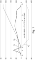
- FIG. 1 A diagram is shown to explain the standard filling process at a hydrogen filling station.
- Curve K 1 is the pressure in or on the receiving tank.
- K 2 shows the mass flow through a connecting hose between the delivery point and the receiving tank.
- K 3 shows the temperature in the tank hose during the refueling process.
- Fig. 1 The time during the refueling process is entered on the abscissa.
- the mass flow in g/s for curve K 3 is shown on the left ordinate.
- the pressure in bar for curve K 1 and the temperature in °C for curve K 3 are shown with the same resolution.
- the refueling hose is connected between the hydrogen delivery unit, i.e. the fuel pump and the receiving tank.
- a high pressure pulse is introduced into the closed hose system via the gas station system, which, however, only lasts a short time. It is then checked whether the pressure can be maintained or not. This ensures and checks whether the connection is fluid-tight. Refueling then begins at time t 2 .
- hydrogen filling stations in Europe have three different tanks: a low-pressure tank up to around 200 bar, a medium-pressure tank up to around 600 bar and a high-pressure tank with a filling between 700 bar and 800 bar.
- the gas station determines that the filling from the low-pressure tank, which was initially started, is no longer running sufficiently quickly and switches to the medium-pressure tank.
- the same determination takes place for the medium-pressure tank, so that a switch is made to the high-pressure tank.
- the refueling process is completed because the maximum permitted pressure is present in the vehicle's tank.
- Further embodiments of hydrogen filling stations use cryogenic liquid hydrogen, which is evaporated and compressed in a similar process and used as highly compressed hydrogen for vehicle refueling.
- FIG. 2 A hydrogen delivery point 60, for example in the form of a gas station, is initially provided on the left side. This has a hydrogen delivery unit 61, on which a connecting piece 62 is provided. On the right side of the figure, a motor vehicle 70 is shown, in which a receiving tank 71 is arranged, which in turn has a connecting piece 72.
- a direct fluid-tight connection would be established with a delivery hose between the hydrogen delivery point 61 or the connecting piece 62 and the receiving tank 61 or its connecting piece 72.
- a measuring system 1 is interposed.
- the measuring system 1 consists of two main components. On the one hand a measuring unit 10 and on the other hand a display unit 20.
- a flow meter 12 is provided in the measuring unit 10 and has a corresponding control and evaluation unit 19. Furthermore, two connecting pieces 11, 16 are provided. A fluid-tight connection is provided between the two connecting pieces 11, 16 and is passed through the flow meter 12. A temperature sensor 13 and a pressure sensor 14 are also arranged at this connection.
- the display unit 20 has a data logger 22 and a measurement display 24. Both the data logger 22 and the measurement display 24 are in communication connection with the control and evaluation unit 19 as well as the temperature sensor 13 and the pressure sensor 14. These connections are in Fig. 1 only hinted at.
- a fluid-tight connection is established between the hydrogen delivery unit 61 or its connection 62 and the connecting piece 11 of the measuring unit 10 as well as the connecting piece 16 of the measuring unit 10 and the connecting piece 72 of the receiving tank 71.
- the hydrogen Since the hydrogen is highly compressed and is initially filled into an empty tank 71, it heats up again in the receiving tank 71. However, since the tanks in the 70 vehicle in particular are only permitted up to a temperature of approx. + 80°C, this heating must largely be reduced or prevented. For this reason, the hydrogen delivered from the hydrogen delivery point 60 via the hydrogen delivery unit 61 is delivered cooled. This results in a temperature in the range from -10°C to -30°C in the fluid-tight connection during the release of the hydrogen.
- a receptacle 15 is provided in the measuring unit 10, which is accessible from the outside.
- an external cooling material 30, for example dry ice is provided in simplified form.
- the receiving device 15 is constructed in such a way that it ends in the area of the flow meter 12 and, for example, has a common wall 17 with the flow meter 12. This creates thermal contact so that the flow meter 12 can be cooled.
- cooling material 30 For example, if dry ice is used as the cooling material 30, it offers the advantage that it is relatively easy to obtain and inexpensive. It can also be used in the explosion-proof area of a gas station because it is inert.
- an infrared connection which can be wired, is provided in accordance with the standards. Information about the refueling status and the like is exchanged between the receiving tank 71 and the hydrogen delivery unit 61 via this infrared connection.
- the infrared connection can be routed past the measuring system 1, as shown with the infrared connection 41.
- the measuring system 1 does not record any information from the infrared channel.
- the measuring system 1 can be actively interposed.
- Two infrared connections 42 are provided for this purpose, which are in Fig. 2 are also marked.
- the advantage of the system according to the invention is that it allows a highly accurate measurement to be carried out, which, however, does not require significantly more time than a standard refueling process.
Landscapes
- Engineering & Computer Science (AREA)
- Physics & Mathematics (AREA)
- Fluid Mechanics (AREA)
- General Physics & Mathematics (AREA)
- Mechanical Engineering (AREA)
- General Engineering & Computer Science (AREA)
- Filling Or Discharging Of Gas Storage Vessels (AREA)
- Vehicle Cleaning, Maintenance, Repair, Refitting, And Outriggers (AREA)
- Measuring Volume Flow (AREA)
- Fuel Cell (AREA)
Claims (14)
- Système de mesure (1) pour déterminer une quantité d'hydrogène distribuée d'un point de distribution d'hydrogène (60), en particulier d'un réservoir d'hydrogène, d'une unité de distribution d'hydrogène (61) présente à cet endroit sous la forme d'un distributeur sur un réservoir de réception (71),avec une unité de mesure (10),dans lequell'unité de mesure (10) présente un débitmètre (12), qui peut être disposé entre l'unité de distribution d'hydrogène (61) sous la forme du distributeur et du réservoir de réception (71),dans lequelle système de mesure (1) est réalisé pour établir une liaison étanche aux fluides entre l'unité de distribution d'hydrogène (61) sous la forme du distributeur et le réservoir de réception (71), dans lequel une liaison étanche aux fluides peut être établie depuis l'unité de distribution d'hydrogène (61) sous la forme d'un distributeur à l'unité de mesure (10) et une liaison étanche aux fluides peut être établie depuis l'unité de mesure (10) au réservoir de réception (71),dans lequell'unité de mesure est réalisée pour acheminer l'hydrogène distribué par l'unité de distribution d'hydrogène (61) sous la forme du distributeur à travers le débitmètre (12) au réservoir de réception (71),caractérisé en ce quele débitmètre (12) présente un refroidissement actif, lequel est réalisé pour refroidir le débitmètre (12) avant le début du transfert de l'hydrogène de telle manière que lors du transfert sensiblement aucun changement de la température ne se produit dans le débitmètre.
- Système de mesure (1) selon la revendication 1,
caractérisé en ce
que le refroidissement actif est un refroidissement externe. - Système de mesure (1) selon la revendication 1 ou 2,
caractérisé en ce
que le refroidissement actif est réalisé au moyen d'un matériau de refroidissement externe (30), en particulier de la neige carbonique. - Système de mesure (1) selon la revendication 1 à 3,
caractérisé en ce
qu'un dispositif de réception (15) est réalisé en contact thermique avec le débitmètre (12) dans l'unité de mesure (10). - Système de mesure (1) selon la revendication 4,
caractérisé en ce
que le dispositif de réception (15) est réalisé en tant qu'espace creux accessible depuis l'extérieur. - Système de mesure (1) selon la revendication 4 ou 5,
caractérisé en ce
qu'une paroi du dispositif de réception (15) est réalisée par un corps du débitmètre (12). - Système de mesure (1) selon l'une quelconque des revendications 1 à 6,
caractérisé en ce
que le débitmètre (12) est réalisé en tant que débitmètre de Coriolis, un débitmètre à ultrasons ou un débitmètre au moyen de buses critiques. - Système de mesure (1) selon l'une quelconque des revendications 1 à 7,
caractérisé en ce
qu'une liaison (41, 42) est prévue pour transmettre des signaux infrarouges bidirectionnels filaires entre l'unité de distribution d'hydrogène (61) et le réservoir de réception (71). - Système de mesure (1) selon la revendication 8,
caractérisé en ce
que la liaison (42) est guidée autour de l'unité de mesure (10). - Système de mesure (1) selon la revendication 8,
caractérisé en ce
que la liaison (42) est guidée à travers l'unité de mesure (10). - Système de mesure (1) selon l'une quelconque des revendications 1 à 10,
caractérisé en ce
que l'unité de mesure (10) présente le débitmètre (12) et une unité de commande et d'évaluation (19). - Système de mesure (1) selon l'une quelconque des revendications 1 à 11,
caractérisé en cequ'est prévue une unité d'affichage (20), qui présente au moins un enregistreur de données (22) et un affichage de mesure (14), etque l'unité d'affichage (20) est en liaison de communication avec l'unité de mesure (10). - Procédé de détermination de la quantité d'hydrogène distribuée d'un point de distribution d'hydrogène (60), en particulier d'un réservoir d'hydrogène, avec une unité de distribution d'hydrogène (61) sous la forme d'un distributeur sur un réservoir de réception (71),dans lequel un système de mesure avec une unité de mesure (10) est utilisé, dans lequel l'unité de mesure (10) présente un débitmètre (12) pouvant être disposé entre l'unité de distribution d'hydrogène (61) sous la forme du distributeur et le réservoir de réception (71),dans lequel une liaison étanche aux fluides entre l'unité de distribution d'hydrogène (61) sous la forme du distributeur et l'unité de mesure (10) ainsi qu'entre l'unité de mesure (10) et le réservoir de réception (71) est établie,dans lequel de l'hydrogène est transféré depuis l'unité de distribution d'hydrogène (61) sous la forme du distributeur en passant par le débitmètre (12) de l'unité de mesure (10) du système de mesure (1) au réservoir de réception (71) par l'intermédiaire de la liaison étanche aux fluides,dans lequel le débit de l'hydrogène est déterminé par le débitmètre (12) pendant la distribution de l'hydrogène depuis l'unité de distribution d'hydrogène (61) au réservoir de réception (71), etcaractérisé en ce quele débitmètre (12) est activement refroidi avant le début du transfert de l'hydrogène depuis l'unité de distribution d'hydrogène (61) au réservoir de réception (71) de sorte que lors du transfert, sensiblement plus aucun changement de la température dans le débitmètre ne se produit.
- Procédé selon la revendication 13,
caractérisé en ce
que le débitmètre (12) est refroidi au moyen du matériau de refroidissement (30) introduit dans l'espace de réception (15), en particulier de la neige carbonique.
Priority Applications (9)
| Application Number | Priority Date | Filing Date | Title |
|---|---|---|---|
| ES20211219T ES2967985T3 (es) | 2020-12-02 | 2020-12-02 | Sistema de medición para determinar la cantidad de hidrógeno emitido así como un procedimiento para ello |
| PL20211219.9T PL4009010T3 (pl) | 2020-12-02 | 2020-12-02 | Układ pomiarowy do określania ilości dostarczanego wodoru i sposób jego działania |
| EP20211219.9A EP4009010B1 (fr) | 2020-12-02 | 2020-12-02 | Système de mesure pour déterminer une quantité livrée d'hydrogène et procédé associé |
| CN202180078438.XA CN116507579A (zh) | 2020-12-02 | 2021-11-18 | 用于确定分配的氢量的测量系统及针对其的方法 |
| KR1020237017793A KR20230098820A (ko) | 2020-12-02 | 2021-11-18 | 수소 분배량 측정 시스템 및 그 방법 |
| US18/033,959 US20230400155A1 (en) | 2020-12-02 | 2021-11-18 | Measuring system for determining a dispensed amount of hydrogen and method therefor |
| JP2023534330A JP2024502543A (ja) | 2020-12-02 | 2021-11-18 | 水素の分配量を特定するための測定システムおよびその方法 |
| PCT/EP2021/082128 WO2022117356A1 (fr) | 2020-12-02 | 2021-11-18 | Système de mesure permettant de déterminer une quantité distribuée d'hydrogène et procédé associé |
| CA3198977A CA3198977A1 (fr) | 2020-12-02 | 2021-11-18 | Systeme de mesure permettant de determiner une quantite distribuee d'hydrogene et procede associe |
Applications Claiming Priority (1)
| Application Number | Priority Date | Filing Date | Title |
|---|---|---|---|
| EP20211219.9A EP4009010B1 (fr) | 2020-12-02 | 2020-12-02 | Système de mesure pour déterminer une quantité livrée d'hydrogène et procédé associé |
Publications (3)
| Publication Number | Publication Date |
|---|---|
| EP4009010A1 EP4009010A1 (fr) | 2022-06-08 |
| EP4009010C0 EP4009010C0 (fr) | 2023-10-04 |
| EP4009010B1 true EP4009010B1 (fr) | 2023-10-04 |
Family
ID=73694825
Family Applications (1)
| Application Number | Title | Priority Date | Filing Date |
|---|---|---|---|
| EP20211219.9A Active EP4009010B1 (fr) | 2020-12-02 | 2020-12-02 | Système de mesure pour déterminer une quantité livrée d'hydrogène et procédé associé |
Country Status (9)
| Country | Link |
|---|---|
| US (1) | US20230400155A1 (fr) |
| EP (1) | EP4009010B1 (fr) |
| JP (1) | JP2024502543A (fr) |
| KR (1) | KR20230098820A (fr) |
| CN (1) | CN116507579A (fr) |
| CA (1) | CA3198977A1 (fr) |
| ES (1) | ES2967985T3 (fr) |
| PL (1) | PL4009010T3 (fr) |
| WO (1) | WO2022117356A1 (fr) |
Families Citing this family (1)
| Publication number | Priority date | Publication date | Assignee | Title |
|---|---|---|---|---|
| IT202400012739A1 (it) * | 2024-06-04 | 2025-12-04 | Iveco Spa | Sistema per il rifornimento di un veicolo a idrogeno |
Citations (2)
| Publication number | Priority date | Publication date | Assignee | Title |
|---|---|---|---|---|
| US6708573B1 (en) * | 2002-09-12 | 2004-03-23 | Air Products And Chemicals, Inc. | Process for filling compressed gas fuel dispensers which utilizes volume and density calculations |
| US20200173607A1 (en) * | 2018-12-04 | 2020-06-04 | Honda Motor Co., Ltd. | Method and system for tank refueling using dispenser and nozzle readings |
Family Cites Families (13)
| Publication number | Priority date | Publication date | Assignee | Title |
|---|---|---|---|---|
| JPH08338749A (ja) * | 1995-06-14 | 1996-12-24 | Oval Corp | コリオリ流量計 |
| JP5707727B2 (ja) * | 2010-04-23 | 2015-04-30 | トヨタ自動車株式会社 | ガス充填方法、ガス充填システム、ガスステーション及び移動体 |
| US20150219278A1 (en) * | 2012-09-19 | 2015-08-06 | Linde Aktiengesellschaft | Integrated dispensing station |
| DE102013001676A1 (de) * | 2012-11-02 | 2014-05-08 | Linde Aktiengesellschaft | Verfahren und Betankungseinrichtung zum Betanken eines Speicherbehälters mit einem unter Druck stehenden, gasförmigen Medium |
| NO2948624T3 (fr) * | 2013-03-15 | 2018-03-31 | ||
| CN104864261B (zh) * | 2015-03-03 | 2017-01-11 | 东京计装(上海)仪表有限公司 | 具有自预冷和低温保持功能的lng加注计量方法及装置 |
| DK201600136A1 (en) * | 2016-03-02 | 2017-10-02 | Nel Hydrogen As | Cooling of a supply pipe in a hydrogen refueling system |
| CN109073156A (zh) * | 2016-04-22 | 2018-12-21 | 株式会社龙野 | 气体填充装置 |
| CN106441473A (zh) * | 2016-08-31 | 2017-02-22 | 烟台中隆仪表有限公司 | 一种免预冷质量流量计 |
| CN109964074B (zh) * | 2016-12-06 | 2021-10-26 | 乔治洛德方法研究和开发液化空气有限公司 | 氢气加注系统 |
| JP6927925B2 (ja) * | 2018-05-30 | 2021-09-01 | Eneos株式会社 | 計量機の流量計故障診断方法及び水素充填装置 |
| US10961109B2 (en) * | 2018-11-16 | 2021-03-30 | China Energy Investment Corporation Limited | Fluid bypass method and system for controlling the temperature of a non-petroleum fuel |
| CN109340578A (zh) * | 2018-12-05 | 2019-02-15 | 上海正帆科技股份有限公司 | 一种液化气体纯化装置及方法 |
-
2020
- 2020-12-02 ES ES20211219T patent/ES2967985T3/es active Active
- 2020-12-02 PL PL20211219.9T patent/PL4009010T3/pl unknown
- 2020-12-02 EP EP20211219.9A patent/EP4009010B1/fr active Active
-
2021
- 2021-11-18 WO PCT/EP2021/082128 patent/WO2022117356A1/fr not_active Ceased
- 2021-11-18 US US18/033,959 patent/US20230400155A1/en not_active Abandoned
- 2021-11-18 JP JP2023534330A patent/JP2024502543A/ja active Pending
- 2021-11-18 CN CN202180078438.XA patent/CN116507579A/zh active Pending
- 2021-11-18 KR KR1020237017793A patent/KR20230098820A/ko not_active Ceased
- 2021-11-18 CA CA3198977A patent/CA3198977A1/fr active Pending
Patent Citations (2)
| Publication number | Priority date | Publication date | Assignee | Title |
|---|---|---|---|---|
| US6708573B1 (en) * | 2002-09-12 | 2004-03-23 | Air Products And Chemicals, Inc. | Process for filling compressed gas fuel dispensers which utilizes volume and density calculations |
| US20200173607A1 (en) * | 2018-12-04 | 2020-06-04 | Honda Motor Co., Ltd. | Method and system for tank refueling using dispenser and nozzle readings |
Also Published As
| Publication number | Publication date |
|---|---|
| EP4009010A1 (fr) | 2022-06-08 |
| WO2022117356A1 (fr) | 2022-06-09 |
| EP4009010C0 (fr) | 2023-10-04 |
| PL4009010T3 (pl) | 2024-03-25 |
| US20230400155A1 (en) | 2023-12-14 |
| CA3198977A1 (fr) | 2022-06-09 |
| ES2967985T3 (es) | 2024-05-06 |
| JP2024502543A (ja) | 2024-01-22 |
| KR20230098820A (ko) | 2023-07-04 |
| CN116507579A (zh) | 2023-07-28 |
Similar Documents
| Publication | Publication Date | Title |
|---|---|---|
| EP0653585B1 (fr) | Procédé et installation pour la remplissage rapide d'un réservoir sous pression avec un fluide gazeux | |
| EP1205704B1 (fr) | Procédé de remplissage d'un réservoir avec du gaz | |
| EP3270034B1 (fr) | Installation de gaz liquide | |
| EP2035739B1 (fr) | Procédé de fonctionnement d'un dispositif destiné au remplissage d'un réservoir de carburant stocké sous forme cryogénique | |
| DE102013108597A1 (de) | Baugruppe zum Bereitstellen eines dosierten Gasstroms, zugehöriges Verfahren, mit einer solchen Baugruppe ausgestatteter Abgasstrang eines Fahrzeugs | |
| DE10218678B4 (de) | Verfahren für ein Gasbetankungssystem und Vorrichtung zum Befüllen eines Druckgasbehälters | |
| WO2008151709A1 (fr) | Réservoir de gaz haute pression et procédé pour remplir un réservoir de gaz haute pression | |
| DE112005002795T5 (de) | Kältemittelbefüllsystem und ein in der Dampfphase vorliegendes Kältemittel verwendendes Verfahren | |
| EP1543309B1 (fr) | Dispositif de fuite de reference pour detecteur renifleur de fuite | |
| WO2022117356A1 (fr) | Système de mesure permettant de déterminer une quantité distribuée d'hydrogène et procédé associé | |
| WO2018028824A1 (fr) | Procédé et dispositif permettant de détecter de manière étalonnable une quantité de gaz | |
| DE19546659C2 (de) | Einrichtung zum Betanken eines Fahrzeugs | |
| DE3433221A1 (de) | Druckfester behaelter fuer feinkoernige, feste schuettgueter | |
| DE102013214044A1 (de) | Verfahren zum Bestimmen der Masse des in einem Kryodrucktank gespeicherten Mediums | |
| DE102006021820B4 (de) | Überfüllschutz für einen Flüssigwasserstofftank | |
| DE102015209621A1 (de) | Kraftfahrzeug mit einem kryogenen Druckbehälter und Verfahren zur Steigerung einer Luftaustauschrate | |
| WO2023108186A1 (fr) | Système de remplissage respectueux de l'environnement de contenant cryogénique de véhicule | |
| EP1387333B1 (fr) | Méthode d'optimisation du plein des locomotives | |
| EP0770815A2 (fr) | Installation de remplissage en gaz | |
| EP1568653A2 (fr) | Système de contrôle de ventilation pour citernes de carburants | |
| WO2024032991A1 (fr) | Réservoir de gaz combustible et système de réservoir de gaz combustible | |
| DE19821559A1 (de) | Verfahren und Einrichtung zur Abgabe meßbarer Mengen von unterschiedlichen Flüssigkeitssorten | |
| DE4420621A1 (de) | Verfahren zum überlaufsicheren Befüllen eines Speicherbehälters | |
| DE102021211085A1 (de) | Betankungseinrichtung für ein mit Wasserstoff oder einem gasförmigen Kraftstoff angetriebenen Fahrzeug und Verfahren zum Betreiben einer Betankungseinrichtung für ein mit Wasserstoff oder einem gasförmigen Kraftstoff angetriebenen Fahrzeug | |
| DE10308687A1 (de) | Prüfleckeinrichtung für einen Schnüffellecksucher |
Legal Events
| Date | Code | Title | Description |
|---|---|---|---|
| PUAI | Public reference made under article 153(3) epc to a published international application that has entered the european phase |
Free format text: ORIGINAL CODE: 0009012 |
|
| STAA | Information on the status of an ep patent application or granted ep patent |
Free format text: STATUS: THE APPLICATION HAS BEEN PUBLISHED |
|
| AK | Designated contracting states |
Kind code of ref document: A1 Designated state(s): AL AT BE BG CH CY CZ DE DK EE ES FI FR GB GR HR HU IE IS IT LI LT LU LV MC MK MT NL NO PL PT RO RS SE SI SK SM TR |
|
| STAA | Information on the status of an ep patent application or granted ep patent |
Free format text: STATUS: REQUEST FOR EXAMINATION WAS MADE |
|
| 17P | Request for examination filed |
Effective date: 20221208 |
|
| RBV | Designated contracting states (corrected) |
Designated state(s): AL AT BE BG CH CY CZ DE DK EE ES FI FR GB GR HR HU IE IS IT LI LT LU LV MC MK MT NL NO PL PT RO RS SE SI SK SM TR |
|
| GRAP | Despatch of communication of intention to grant a patent |
Free format text: ORIGINAL CODE: EPIDOSNIGR1 |
|
| STAA | Information on the status of an ep patent application or granted ep patent |
Free format text: STATUS: GRANT OF PATENT IS INTENDED |
|
| RIC1 | Information provided on ipc code assigned before grant |
Ipc: G01F 1/00 20220101ALI20230605BHEP Ipc: G01F 25/00 20220101ALI20230605BHEP Ipc: F17C 5/06 20060101ALI20230605BHEP Ipc: B67D 7/00 20100101ALI20230605BHEP Ipc: G01F 15/00 20060101AFI20230605BHEP |
|
| INTG | Intention to grant announced |
Effective date: 20230711 |
|
| GRAS | Grant fee paid |
Free format text: ORIGINAL CODE: EPIDOSNIGR3 |
|
| GRAA | (expected) grant |
Free format text: ORIGINAL CODE: 0009210 |
|
| STAA | Information on the status of an ep patent application or granted ep patent |
Free format text: STATUS: THE PATENT HAS BEEN GRANTED |
|
| AK | Designated contracting states |
Kind code of ref document: B1 Designated state(s): AL AT BE BG CH CY CZ DE DK EE ES FI FR GB GR HR HU IE IS IT LI LT LU LV MC MK MT NL NO PL PT RO RS SE SI SK SM TR |
|
| REG | Reference to a national code |
Ref country code: GB Ref legal event code: FG4D Free format text: NOT ENGLISH |
|
| REG | Reference to a national code |
Ref country code: CH Ref legal event code: EP |
|
| REG | Reference to a national code |
Ref country code: IE Ref legal event code: FG4D Free format text: LANGUAGE OF EP DOCUMENT: GERMAN |
|
| REG | Reference to a national code |
Ref country code: DE Ref legal event code: R096 Ref document number: 502020005504 Country of ref document: DE |
|
| U01 | Request for unitary effect filed |
Effective date: 20231005 |
|
| U07 | Unitary effect registered |
Designated state(s): AT BE BG DE DK EE FI FR IT LT LU LV MT NL PT SE SI Effective date: 20231017 |
|
| REG | Reference to a national code |
Ref country code: NO Ref legal event code: T2 Effective date: 20231004 |
|
| U20 | Renewal fee for the european patent with unitary effect paid |
Year of fee payment: 4 Effective date: 20231220 |
|
| PGFP | Annual fee paid to national office [announced via postgrant information from national office to epo] |
Ref country code: NO Payment date: 20231221 Year of fee payment: 4 |
|
| PG25 | Lapsed in a contracting state [announced via postgrant information from national office to epo] |
Ref country code: GR Free format text: LAPSE BECAUSE OF FAILURE TO SUBMIT A TRANSLATION OF THE DESCRIPTION OR TO PAY THE FEE WITHIN THE PRESCRIBED TIME-LIMIT Effective date: 20240105 |
|
| PG25 | Lapsed in a contracting state [announced via postgrant information from national office to epo] |
Ref country code: IS Free format text: LAPSE BECAUSE OF FAILURE TO SUBMIT A TRANSLATION OF THE DESCRIPTION OR TO PAY THE FEE WITHIN THE PRESCRIBED TIME-LIMIT Effective date: 20240204 |
|
| PGFP | Annual fee paid to national office [announced via postgrant information from national office to epo] |
Ref country code: ES Payment date: 20240118 Year of fee payment: 4 |
|
| PG25 | Lapsed in a contracting state [announced via postgrant information from national office to epo] |
Ref country code: IS Free format text: LAPSE BECAUSE OF FAILURE TO SUBMIT A TRANSLATION OF THE DESCRIPTION OR TO PAY THE FEE WITHIN THE PRESCRIBED TIME-LIMIT Effective date: 20240204 Ref country code: GR Free format text: LAPSE BECAUSE OF FAILURE TO SUBMIT A TRANSLATION OF THE DESCRIPTION OR TO PAY THE FEE WITHIN THE PRESCRIBED TIME-LIMIT Effective date: 20240105 |
|
| PGFP | Annual fee paid to national office [announced via postgrant information from national office to epo] |
Ref country code: CZ Payment date: 20231121 Year of fee payment: 4 |
|
| REG | Reference to a national code |
Ref country code: ES Ref legal event code: FG2A Ref document number: 2967985 Country of ref document: ES Kind code of ref document: T3 Effective date: 20240506 |
|
| PG25 | Lapsed in a contracting state [announced via postgrant information from national office to epo] |
Ref country code: RS Free format text: LAPSE BECAUSE OF FAILURE TO SUBMIT A TRANSLATION OF THE DESCRIPTION OR TO PAY THE FEE WITHIN THE PRESCRIBED TIME-LIMIT Effective date: 20231004 Ref country code: HR Free format text: LAPSE BECAUSE OF FAILURE TO SUBMIT A TRANSLATION OF THE DESCRIPTION OR TO PAY THE FEE WITHIN THE PRESCRIBED TIME-LIMIT Effective date: 20231004 |
|
| PGFP | Annual fee paid to national office [announced via postgrant information from national office to epo] |
Ref country code: PL Payment date: 20231123 Year of fee payment: 4 |
|
| REG | Reference to a national code |
Ref country code: DE Ref legal event code: R097 Ref document number: 502020005504 Country of ref document: DE |
|
| PG25 | Lapsed in a contracting state [announced via postgrant information from national office to epo] |
Ref country code: SK Free format text: LAPSE BECAUSE OF FAILURE TO SUBMIT A TRANSLATION OF THE DESCRIPTION OR TO PAY THE FEE WITHIN THE PRESCRIBED TIME-LIMIT Effective date: 20231004 |
|
| PG25 | Lapsed in a contracting state [announced via postgrant information from national office to epo] |
Ref country code: SM Free format text: LAPSE BECAUSE OF FAILURE TO SUBMIT A TRANSLATION OF THE DESCRIPTION OR TO PAY THE FEE WITHIN THE PRESCRIBED TIME-LIMIT Effective date: 20231004 Ref country code: SK Free format text: LAPSE BECAUSE OF FAILURE TO SUBMIT A TRANSLATION OF THE DESCRIPTION OR TO PAY THE FEE WITHIN THE PRESCRIBED TIME-LIMIT Effective date: 20231004 Ref country code: RO Free format text: LAPSE BECAUSE OF FAILURE TO SUBMIT A TRANSLATION OF THE DESCRIPTION OR TO PAY THE FEE WITHIN THE PRESCRIBED TIME-LIMIT Effective date: 20231004 |
|
| PLBE | No opposition filed within time limit |
Free format text: ORIGINAL CODE: 0009261 |
|
| STAA | Information on the status of an ep patent application or granted ep patent |
Free format text: STATUS: NO OPPOSITION FILED WITHIN TIME LIMIT |
|
| PG25 | Lapsed in a contracting state [announced via postgrant information from national office to epo] |
Ref country code: MC Free format text: LAPSE BECAUSE OF FAILURE TO SUBMIT A TRANSLATION OF THE DESCRIPTION OR TO PAY THE FEE WITHIN THE PRESCRIBED TIME-LIMIT Effective date: 20231004 |
|
| PG25 | Lapsed in a contracting state [announced via postgrant information from national office to epo] |
Ref country code: MC Free format text: LAPSE BECAUSE OF FAILURE TO SUBMIT A TRANSLATION OF THE DESCRIPTION OR TO PAY THE FEE WITHIN THE PRESCRIBED TIME-LIMIT Effective date: 20231004 |
|
| 26N | No opposition filed |
Effective date: 20240705 |
|
| REG | Reference to a national code |
Ref country code: IE Ref legal event code: MM4A |
|
| PG25 | Lapsed in a contracting state [announced via postgrant information from national office to epo] |
Ref country code: IE Free format text: LAPSE BECAUSE OF NON-PAYMENT OF DUE FEES Effective date: 20231202 |
|
| PG25 | Lapsed in a contracting state [announced via postgrant information from national office to epo] |
Ref country code: IE Free format text: LAPSE BECAUSE OF NON-PAYMENT OF DUE FEES Effective date: 20231202 |
|
| U21 | Renewal fee for the european patent with unitary effect paid with additional fee |
Year of fee payment: 5 Effective date: 20250530 |
|
| PG25 | Lapsed in a contracting state [announced via postgrant information from national office to epo] |
Ref country code: CY Free format text: LAPSE BECAUSE OF FAILURE TO SUBMIT A TRANSLATION OF THE DESCRIPTION OR TO PAY THE FEE WITHIN THE PRESCRIBED TIME-LIMIT; INVALID AB INITIO Effective date: 20201202 |
|
| PG25 | Lapsed in a contracting state [announced via postgrant information from national office to epo] |
Ref country code: CZ Free format text: LAPSE BECAUSE OF NON-PAYMENT OF DUE FEES Effective date: 20241202 |
|
| U1K | Transfer of rights of the unitary patent after the registration of the unitary effect |
Owner name: HYDROSONIC TECHNOLOGY & METERING GMBH; DE Owner name: TRIGASDM GMBH; DE |
|
| PG25 | Lapsed in a contracting state [announced via postgrant information from national office to epo] |
Ref country code: HU Free format text: LAPSE BECAUSE OF FAILURE TO SUBMIT A TRANSLATION OF THE DESCRIPTION OR TO PAY THE FEE WITHIN THE PRESCRIBED TIME-LIMIT; INVALID AB INITIO Effective date: 20201202 |
|
| GBPC | Gb: european patent ceased through non-payment of renewal fee |
Effective date: 20241202 |
|
| PG25 | Lapsed in a contracting state [announced via postgrant information from national office to epo] |
Ref country code: NO Free format text: LAPSE BECAUSE OF NON-PAYMENT OF DUE FEES Effective date: 20241231 |
|
| PG25 | Lapsed in a contracting state [announced via postgrant information from national office to epo] |
Ref country code: GB Free format text: LAPSE BECAUSE OF NON-PAYMENT OF DUE FEES Effective date: 20241202 |
|
| PG25 | Lapsed in a contracting state [announced via postgrant information from national office to epo] |
Ref country code: TR Free format text: LAPSE BECAUSE OF FAILURE TO SUBMIT A TRANSLATION OF THE DESCRIPTION OR TO PAY THE FEE WITHIN THE PRESCRIBED TIME-LIMIT Effective date: 20231004 |
|
| REG | Reference to a national code |
Ref country code: CH Ref legal event code: U11 Free format text: ST27 STATUS EVENT CODE: U-0-0-U10-U11 (AS PROVIDED BY THE NATIONAL OFFICE) Effective date: 20260101 |
|
| REG | Reference to a national code |
Ref country code: ES Ref legal event code: FD2A Effective date: 20260126 |
|
| U20 | Renewal fee for the european patent with unitary effect paid |
Year of fee payment: 6 Effective date: 20251219 |
|
| PG25 | Lapsed in a contracting state [announced via postgrant information from national office to epo] |
Ref country code: ES Free format text: LAPSE BECAUSE OF NON-PAYMENT OF DUE FEES Effective date: 20241203 |
|
| PGFP | Annual fee paid to national office [announced via postgrant information from national office to epo] |
Ref country code: CH Payment date: 20260101 Year of fee payment: 6 |
|
| PG25 | Lapsed in a contracting state [announced via postgrant information from national office to epo] |
Ref country code: PL Free format text: LAPSE BECAUSE OF NON-PAYMENT OF DUE FEES Effective date: 20241202 |