EP4009659A1 - Casque micro anti-bruit - Google Patents
Casque micro anti-bruit Download PDFInfo
- Publication number
- EP4009659A1 EP4009659A1 EP20211095.3A EP20211095A EP4009659A1 EP 4009659 A1 EP4009659 A1 EP 4009659A1 EP 20211095 A EP20211095 A EP 20211095A EP 4009659 A1 EP4009659 A1 EP 4009659A1
- Authority
- EP
- European Patent Office
- Prior art keywords
- earpiece
- button
- positioning pocket
- headset according
- headset
- Prior art date
- Legal status (The legal status is an assumption and is not a legal conclusion. Google has not performed a legal analysis and makes no representation as to the accuracy of the status listed.)
- Granted
Links
Images

Classifications
-
- H—ELECTRICITY
- H04—ELECTRIC COMMUNICATION TECHNIQUE
- H04R—LOUDSPEAKERS, MICROPHONES, GRAMOPHONE PICK-UPS OR LIKE ACOUSTIC ELECTROMECHANICAL TRANSDUCERS; ELECTRIC HEARING AIDS; PUBLIC ADDRESS SYSTEMS
- H04R1/00—Details of transducers, loudspeakers or microphones
- H04R1/10—Earpieces; Attachments therefor ; Earphones; Monophonic headphones
-
- A—HUMAN NECESSITIES
- A61—MEDICAL OR VETERINARY SCIENCE; HYGIENE
- A61F—FILTERS IMPLANTABLE INTO BLOOD VESSELS; PROSTHESES; DEVICES PROVIDING PATENCY TO, OR PREVENTING COLLAPSING OF, TUBULAR STRUCTURES OF THE BODY, e.g. STENTS; ORTHOPAEDIC, NURSING OR CONTRACEPTIVE DEVICES; FOMENTATION; TREATMENT OR PROTECTION OF EYES OR EARS; BANDAGES, DRESSINGS OR ABSORBENT PADS; FIRST-AID KITS
- A61F11/00—Methods or devices for treatment of the ears or hearing sense; Non-electric hearing aids; Methods or devices for enabling ear patients to achieve auditory perception through physiological senses other than hearing sense; Protective devices for the ears, carried on the body or in the hand
- A61F11/06—Protective devices for the ears
- A61F11/14—Protective devices for the ears external, e.g. earcaps or earmuffs
- A61F11/145—Protective devices for the ears external, e.g. earcaps or earmuffs electric, e.g. for active noise reduction
-
- H—ELECTRICITY
- H04—ELECTRIC COMMUNICATION TECHNIQUE
- H04R—LOUDSPEAKERS, MICROPHONES, GRAMOPHONE PICK-UPS OR LIKE ACOUSTIC ELECTROMECHANICAL TRANSDUCERS; ELECTRIC HEARING AIDS; PUBLIC ADDRESS SYSTEMS
- H04R1/00—Details of transducers, loudspeakers or microphones
- H04R1/10—Earpieces; Attachments therefor ; Earphones; Monophonic headphones
- H04R1/1008—Earpieces of the supra-aural or circum-aural type
-
- H—ELECTRICITY
- H04—ELECTRIC COMMUNICATION TECHNIQUE
- H04R—LOUDSPEAKERS, MICROPHONES, GRAMOPHONE PICK-UPS OR LIKE ACOUSTIC ELECTROMECHANICAL TRANSDUCERS; ELECTRIC HEARING AIDS; PUBLIC ADDRESS SYSTEMS
- H04R1/00—Details of transducers, loudspeakers or microphones
- H04R1/10—Earpieces; Attachments therefor ; Earphones; Monophonic headphones
- H04R1/1041—Mechanical or electronic switches, or control elements
-
- H—ELECTRICITY
- H04—ELECTRIC COMMUNICATION TECHNIQUE
- H04R—LOUDSPEAKERS, MICROPHONES, GRAMOPHONE PICK-UPS OR LIKE ACOUSTIC ELECTROMECHANICAL TRANSDUCERS; ELECTRIC HEARING AIDS; PUBLIC ADDRESS SYSTEMS
- H04R1/00—Details of transducers, loudspeakers or microphones
- H04R1/10—Earpieces; Attachments therefor ; Earphones; Monophonic headphones
- H04R1/1058—Manufacture or assembly
- H04R1/1075—Mountings of transducers in earphones or headphones
-
- H—ELECTRICITY
- H04—ELECTRIC COMMUNICATION TECHNIQUE
- H04R—LOUDSPEAKERS, MICROPHONES, GRAMOPHONE PICK-UPS OR LIKE ACOUSTIC ELECTROMECHANICAL TRANSDUCERS; ELECTRIC HEARING AIDS; PUBLIC ADDRESS SYSTEMS
- H04R1/00—Details of transducers, loudspeakers or microphones
- H04R1/10—Earpieces; Attachments therefor ; Earphones; Monophonic headphones
- H04R1/1091—Details not provided for in groups H04R1/1008 - H04R1/1083
-
- H—ELECTRICITY
- H04—ELECTRIC COMMUNICATION TECHNIQUE
- H04M—TELEPHONIC COMMUNICATION
- H04M1/00—Substation equipment, e.g. for use by subscribers
- H04M1/02—Constructional features of telephone sets
- H04M1/04—Supports for telephone transmitters or receivers
- H04M1/05—Supports for telephone transmitters or receivers specially adapted for use on head, throat or breast
-
- H—ELECTRICITY
- H04—ELECTRIC COMMUNICATION TECHNIQUE
- H04R—LOUDSPEAKERS, MICROPHONES, GRAMOPHONE PICK-UPS OR LIKE ACOUSTIC ELECTROMECHANICAL TRANSDUCERS; ELECTRIC HEARING AIDS; PUBLIC ADDRESS SYSTEMS
- H04R2201/00—Details of transducers, loudspeakers or microphones covered by H04R1/00 but not provided for in any of its subgroups
- H04R2201/10—Details of earpieces, attachments therefor, earphones or monophonic headphones covered by H04R1/10 but not provided for in any of its subgroups
- H04R2201/107—Monophonic and stereophonic headphones with microphone for two-way hands free communication
-
- H—ELECTRICITY
- H04—ELECTRIC COMMUNICATION TECHNIQUE
- H04W—WIRELESS COMMUNICATION NETWORKS
- H04W4/00—Services specially adapted for wireless communication networks; Facilities therefor
- H04W4/06—Selective distribution of broadcast services, e.g. multimedia broadcast multicast service [MBMS]; Services to user groups; One-way selective calling services
- H04W4/10—Push-to-Talk [PTT] or Push-On-Call services
Definitions
- the invention relates to a headset according to the preamble of claim 1.
- a headset which comprises two earpieces, the earpieces being connected to one another via a carrying handle.
- the headset is designed in such a way that the operator can clamp it onto his head using the carrying bracket and the operator's ears are covered by the earpieces.
- the earpieces serve as hearing protection
- loudspeakers are provided in the earpieces in order to transmit information to the operator via a control interface.
- a number of buttons are provided on the earpieces to enable operation of the control interface.
- buttons are difficult to find, making it difficult to operate the control interface.
- Headsets of this type are intended in particular for outdoor work, for example forest work, garden work or the like, in which the operator usually wears work gloves. This circumstance also makes it more difficult to press the corresponding keys in a targeted manner.
- the invention is based on the object of further developing a headset of the generic type in such a way that simple operation of the headset is made possible.
- the headset includes a first earpiece and a second earpiece, the first earpiece and the second earpiece being connected to one another via a connecting element.
- the earpieces each have an inside and an outside, with the insides of the earpieces facing each other and the outsides of the earpieces facing away from each other.
- the earpieces each extend from their bottom to their top in a vertical direction and from their first long side to their second long side in a second transverse direction.
- the first earpiece and/or the second earpiece has a positioning pocket with at least one button on its outside, the positioning pocket extending over a width in the second transverse direction of the earpiece, the width of the positioning pocket being at least 50% of the width measured in the second transverse direction corresponds to the earpiece.
- the positioning pocket extends from a lower end to an upper end in the vertical direction of the earpiece. The upper end of the positioning pocket is formed by a stop edge for the fingertips of an operator to rest against.
- the operator can easily feel the stop edge of the positioning pocket.
- the headset is designed in such a way that the operator can slide his hand into the positioning pocket until the operator's fingertips come to rest on the stop edge of the positioning pocket. If the operator's fingertips lie approximately on the stop edge of the positioning pocket, the hand is in a basic position. To do this, the operator can position their hand on the outside near the bottom of the earpiece and then slide their hand up towards the top of the earpiece until the fingertips contact the stop edge of the positioning pocket. As a result, the operator's hand can always be brought back into the basic position in a simple manner, from which the at least one button in the positioning pocket can be actuated.
- the stop edge of the positioning pocket thus forms an easy-to-touch orientation element, which means that the headset can be operated without visual contact with the headset.
- the stop edge has a depth measured in a first transverse direction from the inside to the outside of the earpiece, the depth of the stop edge corresponding to at least 5% of the depth of the earpiece measured in the first transverse direction.
- the positioning pocket transitions at its lower end, preferably without a step, into a base area forming the outside of the earpiece. Due to the smooth transition between the base of the earpiece and the positioning pocket, the operator's hand can be pushed over the base into the positioning pocket.
- the positioning pocket is delimited in the second transverse direction of the earpiece by a first side wall and a second side wall, the two side walls forming a guide in the transverse direction of the earpiece for lateral guidance of the operator's fingers.
- the first side wall and the second side wall of the positioning pocket form stops for the operator's fingers in the second transverse direction. As soon as the fingers are pushed into the positioning pocket, they are guided vertically through the side walls. If the operator's hand is in the basic position, the hand on the earpiece is aligned by the stop edge of the positioning pocket in the vertical direction and by the side walls in the second transverse direction.
- connection button is preferably designed for connection to a computer unit, in particular a smartphone.
- the at least two keys or the at least three keys are advantageously separated from one another by a separating web. This allows the operator to easily distinguish the keys from each other.
- one of the at least two buttons is recessed in relation to the other button towards the inside of the earpiece in the positioning pocket. The depth offset of the keys to each other also allows the operator to easily distinguish between the keys.
- the at least one button advantageously has a collar that at least partially surrounds the button.
- a side button to be arranged on the first earpiece and/or on the second earpiece outside of the positioning pocket, with the side button and the positioning pocket being arranged relative to one another in such a way that when the operator's hand is in a basic position, the at least one button is in the Positioning pocket and the side button can be operated without having to reposition the hand.
- three buttons in the positioning pocket and the side button can preferably be actuated without having to reposition the hand. This enables a particularly ergonomic operation of the headset.
- the side button is preferably arranged between the underside of the earpiece and the second long side of the earpiece. This makes it easy to press the side button with your thumb.
- the earpiece in the direction of view along the first transverse direction on the outside, has a first centroid and the side button has a second centroid, the distance measured in the vertical direction between the first centroid and the second centroid corresponds to at least 20%, in particular at least 30%, preferably approximately 35% of the height of the earpiece.
- the first centroid of the earpiece preferably lies on the positioning pocket, in particular on the at least one button.
- the distance between the two centroids ensures an ergonomic arrangement of the side button in relation to the at least one button in the positioning pocket. This enables the operator to be able to actuate the at least one button with the index finger, middle finger and/or the ring finger in the basic position of the hand, and also to be able to conveniently actuate the side button with the thumb in the basic position.
- the side button of the first earpiece has three nub-like elevations. This distinguishes the side button on the first earpiece from the side button on the second earpiece.
- the side button of the second earpiece is preferably designed as a circular function button, in particular as a push-to-talk button or a mute button.
- a communication-related function can be activated or deactivated, in particular a push-to-talk function for a radio device that can be connected to the headset or a function for group communication or microphone muting.
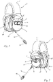
- a headset 1 according to the invention is shown.
- the headset 1 serves, among other things, as hearing protection when working with correspondingly high noise emissions. This includes, for example, working with motor chain saws, brush cutters, trimmers, blowers, angle grinders, stone cutters and the like.
- the headset 1 comprises a first earpiece 2, a second earpiece 3 and a connecting element 4.
- the first earpiece 2 and the second earpiece 3 are connected via the connecting element 4 connected to each other.
- the connecting element 4 is designed as an elastic bracket.
- the bracket is at least partially covered with a cushion to increase the wearing comfort of the headset 1.
- the connecting element 4 can also be designed as a protective helmet or the like. In such an embodiment, the first earpiece 2 and the second earpiece 3 are held on the protective helmet by fastening elements.
- the first earpiece 2 and the second earpiece 3 each comprise a loudspeaker (not shown), the loudspeaker being arranged in the earpieces 2, 3 in each case.
- the headset 1 includes a microphone 33 which is attached to one of the two earpieces 2, 3 via a retaining clip 34.
- the retaining bracket 34 is preferably attached to the second earpiece 3 .
- both earpieces 2, 3 are provided with receptacles 35 for the retaining clip 34, so that the operator can attach the retaining clip 34 either to the first earpiece 2 or to the second earpiece 3.
- the bracket 34 is designed to hold the microphone 33 closer to the operator's mouth when the operator is wearing the headset 1 as intended.
- the first earpiece 2 and the second earpiece 3 each have an outer side 6, 6' and an inner side 5, 5'.
- the insides 5, 5' of the earpieces 2, 3 face each other, the outsides 6, 6' of the earpieces 2, 3 face away from one another.
- the earpieces 2, 3 each extend from their inner side 5, 5' to the outer side 6, 6' in a first transverse direction 31.
- the earpiece 2, 3 in the embodiment in the direction of view Figures 4 and 5 , So in the viewing direction of the first transverse direction 31, approximately oval-shaped. Other forms of the earpiece 2, 3 can also be useful.
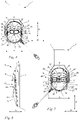
- Individual pages are to be assigned to earpiece 2, 3 as follows: As in 3 shown, the earpieces 2, 3 extend from their bottom 7, 7' to the top 8, 8' in a vertical direction 30. The top 8, 8' is the side of the earpiece 2, 3 facing away from the retaining clip 34, the bottom 7, 7' is the side of the earpiece 2, 3 facing the retaining clip 34.
- the earpieces 2, 3 extend from a first longitudinal side 9, 9' to the second longitudinal side 10, 10' in a second transverse direction 32.
- the first longitudinal side 9, 9' of the earpiece 2, 3 is the side facing the microphone 33
- the second longitudinal side 10, 10' of the earpiece 2, 3 is the side facing away from the microphone 33 .
- the first transverse direction 31, the second transverse direction 32 and the vertical direction 30 of the headset 1 are each aligned perpendicular to one another.
- the first transverse direction 31, the second transverse direction 32 and the vertical direction 30 thus correspond to a rectilinear, orthogonal coordinate system (Cartesian coordinate system), at least with regard to their alignment.
- both earpieces 2, 3 each have a positioning pocket 15, 15' for easy positioning of the operator's hand. It can also be expedient for only the first earpiece 2 or the second earpiece 3 to have a positioning pocket 15, 15'.
- the positioning pocket 15, 15' is arranged on the outside 6, 6' of the earpiece 2, 3. At least one button 22, 22' is arranged in the positioning pocket 15, 15'.
- the positioning pocket 15, 15' comprises a stop edge 20, 20'.
- the stop edge 20, 20' extends in the second transverse direction 32.
- the stop edge 20, 20' is designed in such a way that the fingertips contact the stop edge 20, 20' in the vertical direction 30 when they are inserted into the positioning pocket 15, 15' and strike against it .
- the positioning pocket 15, 15' comprises a first side wall 18, 18' and a second side wall 19, 19'.
- the side walls 18, 18', 19, 19' extend approximately in the vertical direction 30.
- the first side wall 18, 18' and the second side wall 19, 19' each have a first side facing the top 8, 8' of the earpiece 2, 3 late 36 on.
- the first side wall 18, 18' and the second side wall 19, 19' are connected to one another via the stop edge 20, 20'.
- the stop edge 20, 20' adjoins the first ends 36 of the two side walls 18, 18', 19, 19'.
- the side walls 18, 18', 19, 19' form a guide 21, 21' for the operator's fingers in the vertical direction 30.
- the fingers are positioned in the second transverse direction 32 by the guide 21, 21'. In addition, the fingers are prevented from slipping off in the second transverse direction 32 .
- the positioning pocket 15, 15' has a width a which corresponds to the distance between the two side walls 18, 18', 19, 19' measured in the second transverse direction 32.
- the earpiece 2, 3 has a width b, which corresponds to the maximum distance, measured in the second transverse direction 32, between the first longitudinal side 9, 9' and the second longitudinal side 10, 10' of the earpiece 2, 3.
- the width a of the positioning pocket 15 is at least 50%, in particular at least 60%, preferably approximately 75% of the width b of the earpiece 2, 3.
- the positioning pocket 15, 15' has a height d which corresponds to the distance, measured in the vertical direction 30, between a lower end 16, 16' and an upper end 17, 17' of the positioning pocket 15.
- the upper end 17, 17' of the positioning pocket 15, 15' is formed by the stop edge 20, 20' of the positioning pocket 15, 15'.
- the lower end 16, 16' of the positioning pocket 15, 15' is the section of the earpiece 2, 3 in which the positioning pocket 15, 15' merges into a base surface 11, 11' of the earpiece 2, 3 forming the outside 6, 6' .
- this section is formed by an edge 38, 38' without a step between a base surface 39, 39' of the positioning pocket 15, 15' and the base surface 11, 11' of the earpiece 2, 3. It can also be expedient to provide a smooth transition between the bottom surface 39, 39' of the positioning pocket 15, 15' and the bottom surface 11, 11' of the earpiece 2, 3 instead of the edge 38, 38'.
- the lower end 16, 16' of the positioning pocket 15, 15' is also closed off by the second ends 37 of the side walls 18, 18', 19, 19' of the positioning pocket 15, 15' formed.
- the earpiece 2, 3 has a height e which corresponds to the maximum distance measured in the vertical direction 30 between the underside 7, 7' and the top 8, 8' of the earpiece 2, 3.
- the height d of the positioning pocket 15, 15' is at least 15%, in particular at least 25%, preferably approximately 30% of the height e of the earpiece 2, 3.
- the bottom surface 39, 39' of the positioning pocket 15, 15' is designed to be slightly convexly curved.
- an approximation plane 40 approaching the bottom surface 39, 39' of the positioning pocket 15, 15' is shown.
- the approximation plane 40 encloses an angle ⁇ with the inside 5, 5' of the earpiece 2, 3, which is open towards the underside 7, 7' of the earpiece 2, 3.
- the angle ⁇ is at least 5°, in particular approximately 7°.
- the stop edge 20, 20' has a depth f which corresponds to the maximum distance measured in the first transverse direction 31 between the base surface 11 of the earpiece 2, 3 and the base surface 39, 39' of the positioning pocket 15, 15'.
- the earpiece 2, 3 has a depth c ( 3 ) which corresponds to the maximum distance measured in the first transverse direction 31 between the inside 5, 5' and the outside 6, 6' of the earpiece 2, 3.
- the depth f of the stop edge 20, 20' is at least 5% of the depth c of the earpiece 2, 3.
- the headset 1 also includes a control interface, not shown, in order to be able to control various devices via the headset 1 or to be able to perform functions of the headset 1 .
- the headset 1 can be connected to a computer unit, in particular to a smartphone, a tablet, a notebook or the like, via the control interface.
- the exemplary embodiment of the headset 1 includes a radio, a music player and/or the like. In the preferred embodiment, the headset 1 is designed for connection to a radio device.
- the button 22 is designed as a connection button 23 .
- the connection button 23 enables the operator to connect the headset 1 to the computer unit, in particular to a smartphone, tablet, notebook or the like.
- the radio can preferably also be activated via the connection button 23 . If the headset 1 is connected to the computer unit, calls can preferably be accepted and ended via the connection button 23 and language assistants can be activated to operate other applications. It can be advantageous to assign additional functions to the connection key 23 .
- connection button 23 has a width g measured in the second transverse direction 32, which corresponds to at least 50%, in particular at least 60%, preferably approximately 75% of the width a of the positioning pocket 15, 15'. Furthermore, the width g of the connection button 23 corresponds to at least 25%, preferably at least 35%, in particular at least 45% of the width b of the earpiece 2, 3.
- the connection button 23 has a height h measured in the vertical direction 30, which is at least 30%, in particular at least 40% %, preferably approximately 50%, of the height d of the positioning pocket 15, 15'.
- the connection button 23 comprises a raised collar 29 surrounding the connection button 23. The collar 29 enables the connection button 23 to be felt easily.
- the first earpiece 2 includes a side button 27.
- the side button 27 of the first earpiece 2 is arranged between the underside 7 of the first earpiece 2 and the second long side 10 of the earpiece 2 in the exemplary embodiment.
- On the side button 27 of the first earpiece 2 three knob-like elevations 41 are attached. In the exemplary embodiment, the elevations are arranged in a row.
- the nub-like elevations 41 allow the operator to easily identify the side button 27.
- the microphone 33 can be activated and deactivated via the side button 27 of the first earpiece 2.
- the side button 27 is arranged with the positioning pocket 15 and the corresponding connection button 23 in such a way that after the operator places his hand in the basic position, the operator can operate the connection button 23 with his index finger, middle finger and/or ring finger and the side button 27 with his thumb. The hand does not have to be moved. This ensures ergonomic operation of the first earpiece 2 . The operator's hand is then in the basic position when the operator's fingertips rest approximately against the stop edge 20, 20' of the positioning pocket 15, 15'.
- buttons 24, 25, 26 are arranged in the positioning pocket 15' of the second earpiece 3.
- the three keys 24, 25, 26 are a first key 24, a second key 25 and a third key 26.
- the three keys 24, 25, 26 are arranged next to one another in the second transverse direction 32.
- the second button 25 is arranged between the first button 24 and the third button 26 .
- the second button 25 is offset relative to the first button 24 and the third button 26 in the first transverse direction 31, in particular arranged higher.
- the second button 25 is separated from the first button 24 and the third button 26 by a separating web 28 .
- the separating web 28 allows the operator to be able to distinguish the three keys 24, 25, 26 from one another in a simple, haptic manner in their spatial arrangement.
- the first button 24 and the third button 26 are at least partially bordered on their circumference by a raised collar 29 .
- the collar 29 of the first button 24 and the third button 26 connects to the separating web 28 in each case.
- the collar 29 of the first button 24 and the third button 26 allows the operator to easily identify the buttons.
- the volume of the loudspeakers in the two earpieces 2, 3 is preferably set via the first button 24 and the third button 26.
- the radio can be activated and deactivated using the third button 26 .
- the headset 1 can be switched on using the second button 25 .
- the headset 1 can preferably also be coupled to the computer unit, ie a smartphone and the like, via the second button 25 .
- the second button 25 in the exemplary embodiment is preferably also used for navigation during music playback and for station selection when using the radio.
- the second earpiece 3 includes a side button 27'.
- the side button 27 ′ of the second earpiece 3 is arranged between the underside 7 ′ of the second earpiece 3 and the first longitudinal side 9 ′ of the second earpiece 3 .
- the side key 27' has a circular basic shape ( 1 ). Due to the fact that the side button 27 of the first earpiece 2 and the side button 27' of the second earpiece 3 are designed differently, the two side buttons 27, 27' are easy for the operator to distinguish.
- the side key 27' is designed as a communication-related function key, in particular a push-to-talk key or a mute key.
- the side button 27' of the second earpiece 3 and the buttons 24, 25, 26 in the positioning pocket 15' are arranged in such a way that the three buttons 24, 25, 26 and the side button 27 can be actuated from the basic position of the operator's hand.
- the first key 24 can preferably be actuated using the ring finger, the second key 25 using the middle finger, the third key 26 using the index finger and the side key 27' using the thumb. This means that all keys can be pressed from the basic position of the hand without having to reposition the hand.
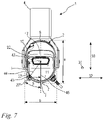
- the headset 1 according to the invention is shown in a partial side view of the first earpiece 2 .
- the first earpiece 2 has a first centroid 42 in the viewing direction along the first transverse direction 31 directed towards the outside 6 .
- the first centroid 42 is arranged, in particular approximately centrally, in the positioning pocket 15 .
- the first centroid 42 is arranged, in particular approximately centrally, in the at least one key 22 .
- the side button 27 of the earpiece 2 has a second centroid 43 in the viewing direction along the first transverse direction 31 directed towards the outside 6 .
- the first centroid 42 of the first earpiece 2 and the second centroid 43 of the side button 27 have a distance i measured in the vertical direction 30, with the distance i being at least 20%, in particular at least 30%, preferably around 35% of the height e of the earpiece 2 is equivalent to.
- the first centroid 42 of the first earpiece 2 and the second centroid 43 of the side button 27 have a distance j measured in the second transverse direction 32, the distance j being at least 20%, in particular at least 30%, preferably approximately 35% of the width b of the earpiece 2 corresponds.
- a longitudinal line 45 oriented in the vertical direction 30 runs through the first centroid 42 of the earpiece 2.
- a connecting line 44 is also shown, which runs through the first surface point 42 and through the second surface point 43 and at the same time intersects the longitudinal line 45.
- the longitudinal straight line 45 and the connecting straight line 44 span an angle ⁇ , the angle ⁇ being open toward the underside 7 of the first earpiece 2 .
- the angle ⁇ is in a range from 15° to 60°, preferably from 25° to 45°.
- the angle ⁇ is preferably approximately 35°.
- first earpiece 2 and the second earpiece 3 are essentially mirror-symmetrical with respect to a plane spanned by the vertical direction 30 and the second transverse direction 32 .
- the above-described relationships between the arrangement of the side button 27 and the centroid 42 of the first earpiece 2 also apply to the second earpiece 3.
Landscapes
- Engineering & Computer Science (AREA)
- Acoustics & Sound (AREA)
- Physics & Mathematics (AREA)
- Signal Processing (AREA)
- Health & Medical Sciences (AREA)
- Life Sciences & Earth Sciences (AREA)
- Vascular Medicine (AREA)
- Biophysics (AREA)
- Otolaryngology (AREA)
- Psychology (AREA)
- Biomedical Technology (AREA)
- Heart & Thoracic Surgery (AREA)
- Animal Behavior & Ethology (AREA)
- General Health & Medical Sciences (AREA)
- Public Health (AREA)
- Veterinary Medicine (AREA)
- Manufacturing & Machinery (AREA)
- Telephone Set Structure (AREA)
Priority Applications (3)
| Application Number | Priority Date | Filing Date | Title |
|---|---|---|---|
| EP20211095.3A EP4009659B1 (fr) | 2020-12-01 | 2020-12-01 | Casque micro anti-bruit |
| US17/536,034 US11937036B2 (en) | 2020-12-01 | 2021-11-28 | Headset |
| CN202111450143.9A CN114584886A (zh) | 2020-12-01 | 2021-12-01 | 耳机 |
Applications Claiming Priority (1)
| Application Number | Priority Date | Filing Date | Title |
|---|---|---|---|
| EP20211095.3A EP4009659B1 (fr) | 2020-12-01 | 2020-12-01 | Casque micro anti-bruit |
Publications (2)
| Publication Number | Publication Date |
|---|---|
| EP4009659A1 true EP4009659A1 (fr) | 2022-06-08 |
| EP4009659B1 EP4009659B1 (fr) | 2024-09-04 |
Family
ID=73698523
Family Applications (1)
| Application Number | Title | Priority Date | Filing Date |
|---|---|---|---|
| EP20211095.3A Active EP4009659B1 (fr) | 2020-12-01 | 2020-12-01 | Casque micro anti-bruit |
Country Status (3)
| Country | Link |
|---|---|
| US (1) | US11937036B2 (fr) |
| EP (1) | EP4009659B1 (fr) |
| CN (1) | CN114584886A (fr) |
Families Citing this family (10)
| Publication number | Priority date | Publication date | Assignee | Title |
|---|---|---|---|---|
| USD968365S1 (en) * | 2019-10-18 | 2022-11-01 | Jsp Limited | Ear defender |
| USD941798S1 (en) * | 2020-01-21 | 2022-01-25 | 3M Innovative Properties Company | Headset |
| USD1024004S1 (en) * | 2021-10-22 | 2024-04-23 | Guangzhou OPSMEN Tech. Co., Ltd | Electronic hearing protector |
| CA214014S (en) * | 2021-11-08 | 2023-05-02 | ODM GmbH | Earcup for headphones |
| USD1017576S1 (en) * | 2021-12-07 | 2024-03-12 | Tao Peng | Headphone |
| US20230179697A1 (en) * | 2021-12-07 | 2023-06-08 | Rugged Race Products, Inc. | Push to talk radio lock |
| USD1095491S1 (en) * | 2023-08-31 | 2025-09-30 | ODM GmbH | Headphone |
| USD1006784S1 (en) * | 2023-09-19 | 2023-12-05 | Shenzhen Yinzhuo Technology Co., Ltd. | Headphone |
| USD1012065S1 (en) * | 2023-09-21 | 2024-01-23 | Shengbo ZHANG | Foldable headphone |
| USD1091501S1 (en) * | 2023-11-08 | 2025-09-02 | Wei Chen | Gaming headphone |
Citations (1)
| Publication number | Priority date | Publication date | Assignee | Title |
|---|---|---|---|---|
| EP3451689A1 (fr) | 2017-08-31 | 2019-03-06 | Honeywell International Inc. | Interface de commande pour casque de protection auditive |
Family Cites Families (15)
| Publication number | Priority date | Publication date | Assignee | Title |
|---|---|---|---|---|
| SE511947C2 (sv) * | 1997-08-15 | 1999-12-20 | Peltor Ab | Hörselskydd med regleringsknappar nedsänkta i ena hörselkåpan |
| AR035939A1 (es) * | 2002-03-04 | 2004-07-28 | Rolla Jose Maria | Mejoras en auriculares plegables |
| US20050238181A1 (en) * | 2003-11-27 | 2005-10-27 | Sigvard Nilsson | Hearing protector |
| US9025806B2 (en) * | 2013-01-08 | 2015-05-05 | The Ketchum Group | Headphone assembly |
| CN105208475A (zh) * | 2014-06-30 | 2015-12-30 | Gn奈康有限公司 | 耳机 |
| US9998850B2 (en) * | 2014-07-02 | 2018-06-12 | Sonetyics Holdings, Inc. | Multiple communication mode headset |
| KR101570299B1 (ko) * | 2014-09-04 | 2015-11-18 | 엘지전자 주식회사 | 헤드셋 |
| US10111014B2 (en) * | 2015-08-10 | 2018-10-23 | Team Ip Holdings, Llc | Multi-source audio amplification and ear protection devices |
| GB2557120C (en) * | 2015-09-17 | 2021-03-31 | Motorola Solutions Inc | Rotatable push-to-talk (PTT) button for talkgroup selection and PTT communication initiation |
| EP3466104B1 (fr) * | 2016-05-26 | 2020-06-10 | 3M Innovative Properties Company | Casque acoustique avec composants intégrés de communication numérique et analogique bidirectionnelle |
| US11284185B2 (en) * | 2016-12-15 | 2022-03-22 | JLBF Enterprises | Protective headphone cover |
| WO2019100081A2 (fr) * | 2017-11-20 | 2019-05-23 | Apple Inc. | Casque d'écoute |
| US10872592B2 (en) * | 2017-12-15 | 2020-12-22 | Skullcandy, Inc. | Noise-canceling headphones including multiple vibration members and related methods |
| US20190342664A1 (en) * | 2018-05-03 | 2019-11-07 | Plantronics, Inc. | Control device with mute functionality for a headset audio system and headset audio system |
| EP4094449B1 (fr) * | 2020-01-21 | 2023-12-13 | 3M Innovative Properties Company | Système de compactage de câbles pour équipement de protection personelle |
-
2020
- 2020-12-01 EP EP20211095.3A patent/EP4009659B1/fr active Active
-
2021
- 2021-11-28 US US17/536,034 patent/US11937036B2/en active Active
- 2021-12-01 CN CN202111450143.9A patent/CN114584886A/zh active Pending
Patent Citations (1)
| Publication number | Priority date | Publication date | Assignee | Title |
|---|---|---|---|---|
| EP3451689A1 (fr) | 2017-08-31 | 2019-03-06 | Honeywell International Inc. | Interface de commande pour casque de protection auditive |
Non-Patent Citations (3)
| Title |
|---|
| HUSQVARNA: "Husqvarna Workshop manual Hearing Protector X-COM R", 16 April 2020 (2020-04-16), XP055789876, Retrieved from the Internet <URL:https://www.manualslib.com/manual/1789010/Husqvarna-X-Com-R.html> [retrieved on 20210325] * |
| HUSQVARNA: "HUSQVARNA ZUBEHÖR UND BEKLEIDUNG Katalog 2011 - Gehörschutz", 7 March 2011 (2011-03-07), XP055789824, Retrieved from the Internet <URL:https://issuu.com/husqvarna/docs/husqvarna_acc_2011_de> [retrieved on 20210325] * |
| HUSQVARNA: "Husqvarna-X-Com-R Hearing Protector Manual", 5 July 2019 (2019-07-05), XP055789837, Retrieved from the Internet <URL:https://www.manualslib.de/download/575441/Husqvarna-X-Com-R-Hp310-1.html> [retrieved on 20210325] * |
Also Published As
| Publication number | Publication date |
|---|---|
| CN114584886A (zh) | 2022-06-03 |
| US20220174387A1 (en) | 2022-06-02 |
| EP4009659B1 (fr) | 2024-09-04 |
| US11937036B2 (en) | 2024-03-19 |
Similar Documents
| Publication | Publication Date | Title |
|---|---|---|
| EP4009659B1 (fr) | Casque micro anti-bruit | |
| EP0892413B1 (fr) | Bouton poussoir | |
| EP3115863B1 (fr) | Élément de commande | |
| DE10041590B4 (de) | Lenkrad | |
| DE102010044613A1 (de) | Schleifgerät | |
| DE60121728T2 (de) | Anordnung in verbindung mit einer steuerungseinrichtung | |
| EP2595782B1 (fr) | Dispositif de levage | |
| DE102023103713A1 (de) | Steueranordnung für tragbare elektronische vorrichtung | |
| EP2060372A1 (fr) | Appareil de bureau destiné à traiter des feuilles | |
| EP3207302B1 (fr) | Dispositif de retenue pour une tôle-témoin | |
| DE202022102273U1 (de) | Vorrichtung zum manuellen Einbringen von Löchern und/oder Nieten in ein Werkstück | |
| DE2134265C2 (de) | Fahrzeug-Fernsprech-Handapparat und Auflage für diesen Apparat | |
| EP4350474A1 (fr) | Adaptateur de commande pour un terminal mobile pour la commande à distance d'un engin de chantier et procédé de commande à distance | |
| EP3064250A1 (fr) | Auto-piqueur et piqueur destiné au perçage local d'une peau humaine ou animale et agencement d'auto-piqueur | |
| DE102019125662A1 (de) | Bedienhilfe, Fernsteuerung und Verfahren zur Fernsteuerung | |
| DE102020128613B3 (de) | Drucktastenbetätigungshilfe sowie Gehörschutzkapsel mit Kommunikationssystem und Drucktaste | |
| DE102008019312B4 (de) | Ophthalmologisches Handgerät | |
| EP2060371A2 (fr) | Appareil de bureau destiné à estampiller des feuilles | |
| DE102018211111A1 (de) | Sicherheitssteuervorrichtung, Fahrzeuginnenverkleidungsteil umfassend eine entsprechende Sicherheitssteuervorrichtung und Verfahren zum Steuern eines Schließvorgangs und/oder Öffnungsvorgangs eines Fahrzeugfensters | |
| DE102019100500A1 (de) | Datenübertragungsvorrichtung zur Kommunikation und/oder Steuerung | |
| LU100917B1 (de) | Werkzeug | |
| DE102007026110A1 (de) | Bedienelement zur Steuerung von Programmen eines Computers oder elektronischen Gerätes | |
| EP3556714B1 (fr) | Commutateur de commande permettant d'opérer une grue | |
| DE1754480U (de) | Zugentlastungsstueck. | |
| DE4447256A1 (de) | Locher zur Ausbildung einer Mehrzahl von Löchern |
Legal Events
| Date | Code | Title | Description |
|---|---|---|---|
| PUAI | Public reference made under article 153(3) epc to a published international application that has entered the european phase |
Free format text: ORIGINAL CODE: 0009012 |
|
| STAA | Information on the status of an ep patent application or granted ep patent |
Free format text: STATUS: THE APPLICATION HAS BEEN PUBLISHED |
|
| AK | Designated contracting states |
Kind code of ref document: A1 Designated state(s): AL AT BE BG CH CY CZ DE DK EE ES FI FR GB GR HR HU IE IS IT LI LT LU LV MC MK MT NL NO PL PT RO RS SE SI SK SM TR |
|
| STAA | Information on the status of an ep patent application or granted ep patent |
Free format text: STATUS: REQUEST FOR EXAMINATION WAS MADE |
|
| 17P | Request for examination filed |
Effective date: 20221208 |
|
| RBV | Designated contracting states (corrected) |
Designated state(s): AL AT BE BG CH CY CZ DE DK EE ES FI FR GB GR HR HU IE IS IT LI LT LU LV MC MK MT NL NO PL PT RO RS SE SI SK SM TR |
|
| GRAP | Despatch of communication of intention to grant a patent |
Free format text: ORIGINAL CODE: EPIDOSNIGR1 |
|
| STAA | Information on the status of an ep patent application or granted ep patent |
Free format text: STATUS: GRANT OF PATENT IS INTENDED |
|
| INTG | Intention to grant announced |
Effective date: 20240327 |
|
| RIC1 | Information provided on ipc code assigned before grant |
Ipc: H04M 1/05 20060101ALN20240315BHEP Ipc: H04M 1/60 20060101ALN20240315BHEP Ipc: A61F 11/14 20060101ALI20240315BHEP Ipc: H04R 1/10 20060101AFI20240315BHEP |
|
| GRAS | Grant fee paid |
Free format text: ORIGINAL CODE: EPIDOSNIGR3 |
|
| GRAA | (expected) grant |
Free format text: ORIGINAL CODE: 0009210 |
|
| STAA | Information on the status of an ep patent application or granted ep patent |
Free format text: STATUS: THE PATENT HAS BEEN GRANTED |
|
| AK | Designated contracting states |
Kind code of ref document: B1 Designated state(s): AL AT BE BG CH CY CZ DE DK EE ES FI FR GB GR HR HU IE IS IT LI LT LU LV MC MK MT NL NO PL PT RO RS SE SI SK SM TR |
|
| REG | Reference to a national code |
Ref country code: GB Ref legal event code: FG4D Free format text: NOT ENGLISH |
|
| REG | Reference to a national code |
Ref country code: CH Ref legal event code: EP |
|
| REG | Reference to a national code |
Ref country code: IE Ref legal event code: FG4D Free format text: LANGUAGE OF EP DOCUMENT: GERMAN |
|
| REG | Reference to a national code |
Ref country code: DE Ref legal event code: R096 Ref document number: 502020009089 Country of ref document: DE |
|
| REG | Reference to a national code |
Ref country code: LT Ref legal event code: MG9D |
|
| REG | Reference to a national code |
Ref country code: NL Ref legal event code: MP Effective date: 20240904 |
|
| PG25 | Lapsed in a contracting state [announced via postgrant information from national office to epo] |
Ref country code: NO Free format text: LAPSE BECAUSE OF FAILURE TO SUBMIT A TRANSLATION OF THE DESCRIPTION OR TO PAY THE FEE WITHIN THE PRESCRIBED TIME-LIMIT Effective date: 20241204 |
|
| PG25 | Lapsed in a contracting state [announced via postgrant information from national office to epo] |
Ref country code: PL Free format text: LAPSE BECAUSE OF FAILURE TO SUBMIT A TRANSLATION OF THE DESCRIPTION OR TO PAY THE FEE WITHIN THE PRESCRIBED TIME-LIMIT Effective date: 20240904 Ref country code: GR Free format text: LAPSE BECAUSE OF FAILURE TO SUBMIT A TRANSLATION OF THE DESCRIPTION OR TO PAY THE FEE WITHIN THE PRESCRIBED TIME-LIMIT Effective date: 20241205 Ref country code: FI Free format text: LAPSE BECAUSE OF FAILURE TO SUBMIT A TRANSLATION OF THE DESCRIPTION OR TO PAY THE FEE WITHIN THE PRESCRIBED TIME-LIMIT Effective date: 20240904 |
|
| PG25 | Lapsed in a contracting state [announced via postgrant information from national office to epo] |
Ref country code: BG Free format text: LAPSE BECAUSE OF FAILURE TO SUBMIT A TRANSLATION OF THE DESCRIPTION OR TO PAY THE FEE WITHIN THE PRESCRIBED TIME-LIMIT Effective date: 20240904 |
|
| PG25 | Lapsed in a contracting state [announced via postgrant information from national office to epo] |
Ref country code: LV Free format text: LAPSE BECAUSE OF FAILURE TO SUBMIT A TRANSLATION OF THE DESCRIPTION OR TO PAY THE FEE WITHIN THE PRESCRIBED TIME-LIMIT Effective date: 20240904 |
|
| PG25 | Lapsed in a contracting state [announced via postgrant information from national office to epo] |
Ref country code: HR Free format text: LAPSE BECAUSE OF FAILURE TO SUBMIT A TRANSLATION OF THE DESCRIPTION OR TO PAY THE FEE WITHIN THE PRESCRIBED TIME-LIMIT Effective date: 20240904 |
|
| PG25 | Lapsed in a contracting state [announced via postgrant information from national office to epo] |
Ref country code: ES Free format text: LAPSE BECAUSE OF FAILURE TO SUBMIT A TRANSLATION OF THE DESCRIPTION OR TO PAY THE FEE WITHIN THE PRESCRIBED TIME-LIMIT Effective date: 20240904 Ref country code: RS Free format text: LAPSE BECAUSE OF FAILURE TO SUBMIT A TRANSLATION OF THE DESCRIPTION OR TO PAY THE FEE WITHIN THE PRESCRIBED TIME-LIMIT Effective date: 20241204 |
|
| PG25 | Lapsed in a contracting state [announced via postgrant information from national office to epo] |
Ref country code: RS Free format text: LAPSE BECAUSE OF FAILURE TO SUBMIT A TRANSLATION OF THE DESCRIPTION OR TO PAY THE FEE WITHIN THE PRESCRIBED TIME-LIMIT Effective date: 20241204 Ref country code: PL Free format text: LAPSE BECAUSE OF FAILURE TO SUBMIT A TRANSLATION OF THE DESCRIPTION OR TO PAY THE FEE WITHIN THE PRESCRIBED TIME-LIMIT Effective date: 20240904 Ref country code: NO Free format text: LAPSE BECAUSE OF FAILURE TO SUBMIT A TRANSLATION OF THE DESCRIPTION OR TO PAY THE FEE WITHIN THE PRESCRIBED TIME-LIMIT Effective date: 20241204 Ref country code: LV Free format text: LAPSE BECAUSE OF FAILURE TO SUBMIT A TRANSLATION OF THE DESCRIPTION OR TO PAY THE FEE WITHIN THE PRESCRIBED TIME-LIMIT Effective date: 20240904 Ref country code: HR Free format text: LAPSE BECAUSE OF FAILURE TO SUBMIT A TRANSLATION OF THE DESCRIPTION OR TO PAY THE FEE WITHIN THE PRESCRIBED TIME-LIMIT Effective date: 20240904 Ref country code: GR Free format text: LAPSE BECAUSE OF FAILURE TO SUBMIT A TRANSLATION OF THE DESCRIPTION OR TO PAY THE FEE WITHIN THE PRESCRIBED TIME-LIMIT Effective date: 20241205 Ref country code: FI Free format text: LAPSE BECAUSE OF FAILURE TO SUBMIT A TRANSLATION OF THE DESCRIPTION OR TO PAY THE FEE WITHIN THE PRESCRIBED TIME-LIMIT Effective date: 20240904 Ref country code: ES Free format text: LAPSE BECAUSE OF FAILURE TO SUBMIT A TRANSLATION OF THE DESCRIPTION OR TO PAY THE FEE WITHIN THE PRESCRIBED TIME-LIMIT Effective date: 20240904 Ref country code: BG Free format text: LAPSE BECAUSE OF FAILURE TO SUBMIT A TRANSLATION OF THE DESCRIPTION OR TO PAY THE FEE WITHIN THE PRESCRIBED TIME-LIMIT Effective date: 20240904 |
|
| PG25 | Lapsed in a contracting state [announced via postgrant information from national office to epo] |
Ref country code: NL Free format text: LAPSE BECAUSE OF FAILURE TO SUBMIT A TRANSLATION OF THE DESCRIPTION OR TO PAY THE FEE WITHIN THE PRESCRIBED TIME-LIMIT Effective date: 20240904 |
|
| PG25 | Lapsed in a contracting state [announced via postgrant information from national office to epo] |
Ref country code: IS Free format text: LAPSE BECAUSE OF FAILURE TO SUBMIT A TRANSLATION OF THE DESCRIPTION OR TO PAY THE FEE WITHIN THE PRESCRIBED TIME-LIMIT Effective date: 20250104 Ref country code: PT Free format text: LAPSE BECAUSE OF FAILURE TO SUBMIT A TRANSLATION OF THE DESCRIPTION OR TO PAY THE FEE WITHIN THE PRESCRIBED TIME-LIMIT Effective date: 20250106 |
|
| PG25 | Lapsed in a contracting state [announced via postgrant information from national office to epo] |
Ref country code: RO Free format text: LAPSE BECAUSE OF FAILURE TO SUBMIT A TRANSLATION OF THE DESCRIPTION OR TO PAY THE FEE WITHIN THE PRESCRIBED TIME-LIMIT Effective date: 20240904 Ref country code: SM Free format text: LAPSE BECAUSE OF FAILURE TO SUBMIT A TRANSLATION OF THE DESCRIPTION OR TO PAY THE FEE WITHIN THE PRESCRIBED TIME-LIMIT Effective date: 20240904 |
|
| PG25 | Lapsed in a contracting state [announced via postgrant information from national office to epo] |
Ref country code: EE Free format text: LAPSE BECAUSE OF FAILURE TO SUBMIT A TRANSLATION OF THE DESCRIPTION OR TO PAY THE FEE WITHIN THE PRESCRIBED TIME-LIMIT Effective date: 20240904 |
|
| PG25 | Lapsed in a contracting state [announced via postgrant information from national office to epo] |
Ref country code: CZ Free format text: LAPSE BECAUSE OF FAILURE TO SUBMIT A TRANSLATION OF THE DESCRIPTION OR TO PAY THE FEE WITHIN THE PRESCRIBED TIME-LIMIT Effective date: 20240904 |
|
| PG25 | Lapsed in a contracting state [announced via postgrant information from national office to epo] |
Ref country code: SK Free format text: LAPSE BECAUSE OF FAILURE TO SUBMIT A TRANSLATION OF THE DESCRIPTION OR TO PAY THE FEE WITHIN THE PRESCRIBED TIME-LIMIT Effective date: 20240904 Ref country code: IT Free format text: LAPSE BECAUSE OF FAILURE TO SUBMIT A TRANSLATION OF THE DESCRIPTION OR TO PAY THE FEE WITHIN THE PRESCRIBED TIME-LIMIT Effective date: 20240904 |
|
| REG | Reference to a national code |
Ref country code: DE Ref legal event code: R097 Ref document number: 502020009089 Country of ref document: DE |
|
| PG25 | Lapsed in a contracting state [announced via postgrant information from national office to epo] |
Ref country code: MC Free format text: LAPSE BECAUSE OF FAILURE TO SUBMIT A TRANSLATION OF THE DESCRIPTION OR TO PAY THE FEE WITHIN THE PRESCRIBED TIME-LIMIT Effective date: 20240904 |
|
| PG25 | Lapsed in a contracting state [announced via postgrant information from national office to epo] |
Ref country code: DK Free format text: LAPSE BECAUSE OF FAILURE TO SUBMIT A TRANSLATION OF THE DESCRIPTION OR TO PAY THE FEE WITHIN THE PRESCRIBED TIME-LIMIT Effective date: 20240904 |
|
| PLBE | No opposition filed within time limit |
Free format text: ORIGINAL CODE: 0009261 |
|
| STAA | Information on the status of an ep patent application or granted ep patent |
Free format text: STATUS: NO OPPOSITION FILED WITHIN TIME LIMIT |
|
| REG | Reference to a national code |
Ref country code: CH Ref legal event code: PL |
|
| 26N | No opposition filed |
Effective date: 20250605 |
|
| PG25 | Lapsed in a contracting state [announced via postgrant information from national office to epo] |
Ref country code: LU Free format text: LAPSE BECAUSE OF NON-PAYMENT OF DUE FEES Effective date: 20241201 |
|
| GBPC | Gb: european patent ceased through non-payment of renewal fee |
Effective date: 20241204 |
|
| PG25 | Lapsed in a contracting state [announced via postgrant information from national office to epo] |
Ref country code: SE Free format text: LAPSE BECAUSE OF FAILURE TO SUBMIT A TRANSLATION OF THE DESCRIPTION OR TO PAY THE FEE WITHIN THE PRESCRIBED TIME-LIMIT Effective date: 20240904 |
|
| REG | Reference to a national code |
Ref country code: BE Ref legal event code: MM Effective date: 20241231 |
|
| PG25 | Lapsed in a contracting state [announced via postgrant information from national office to epo] |
Ref country code: BE Free format text: LAPSE BECAUSE OF NON-PAYMENT OF DUE FEES Effective date: 20241231 Ref country code: GB Free format text: LAPSE BECAUSE OF NON-PAYMENT OF DUE FEES Effective date: 20241204 |
|
| PG25 | Lapsed in a contracting state [announced via postgrant information from national office to epo] |
Ref country code: FR Free format text: LAPSE BECAUSE OF NON-PAYMENT OF DUE FEES Effective date: 20241231 |
|
| PG25 | Lapsed in a contracting state [announced via postgrant information from national office to epo] |
Ref country code: CH Free format text: LAPSE BECAUSE OF NON-PAYMENT OF DUE FEES Effective date: 20241231 |
|
| PG25 | Lapsed in a contracting state [announced via postgrant information from national office to epo] |
Ref country code: IE Free format text: LAPSE BECAUSE OF NON-PAYMENT OF DUE FEES Effective date: 20241201 |
|
| PGFP | Annual fee paid to national office [announced via postgrant information from national office to epo] |
Ref country code: AT Payment date: 20260113 Year of fee payment: 5 |
|
| PG25 | Lapsed in a contracting state [announced via postgrant information from national office to epo] |
Ref country code: CY Free format text: LAPSE BECAUSE OF FAILURE TO SUBMIT A TRANSLATION OF THE DESCRIPTION OR TO PAY THE FEE WITHIN THE PRESCRIBED TIME-LIMIT; INVALID AB INITIO Effective date: 20201201 |
|
| PGFP | Annual fee paid to national office [announced via postgrant information from national office to epo] |
Ref country code: DE Payment date: 20251229 Year of fee payment: 6 |