EP4009659B1 - Gehörschützer mit headset-funktion - Google Patents
Gehörschützer mit headset-funktion Download PDFInfo
- Publication number
- EP4009659B1 EP4009659B1 EP20211095.3A EP20211095A EP4009659B1 EP 4009659 B1 EP4009659 B1 EP 4009659B1 EP 20211095 A EP20211095 A EP 20211095A EP 4009659 B1 EP4009659 B1 EP 4009659B1
- Authority
- EP
- European Patent Office
- Prior art keywords
- earpiece
- button
- earpieces
- positioning pocket
- transverse direction
- Prior art date
- Legal status (The legal status is an assumption and is not a legal conclusion. Google has not performed a legal analysis and makes no representation as to the accuracy of the status listed.)
- Active
Links
Images


Classifications
-
- H—ELECTRICITY
- H04—ELECTRIC COMMUNICATION TECHNIQUE
- H04R—LOUDSPEAKERS, MICROPHONES, GRAMOPHONE PICK-UPS OR LIKE ACOUSTIC ELECTROMECHANICAL TRANSDUCERS; ELECTRIC HEARING AIDS; PUBLIC ADDRESS SYSTEMS
- H04R1/00—Details of transducers, loudspeakers or microphones
- H04R1/10—Earpieces; Attachments therefor ; Earphones; Monophonic headphones
- H04R1/1008—Earpieces of the supra-aural or circum-aural type
-
- H—ELECTRICITY
- H04—ELECTRIC COMMUNICATION TECHNIQUE
- H04R—LOUDSPEAKERS, MICROPHONES, GRAMOPHONE PICK-UPS OR LIKE ACOUSTIC ELECTROMECHANICAL TRANSDUCERS; ELECTRIC HEARING AIDS; PUBLIC ADDRESS SYSTEMS
- H04R1/00—Details of transducers, loudspeakers or microphones
- H04R1/10—Earpieces; Attachments therefor ; Earphones; Monophonic headphones
- H04R1/1041—Mechanical or electronic switches, or control elements
-
- A—HUMAN NECESSITIES
- A61—MEDICAL OR VETERINARY SCIENCE; HYGIENE
- A61F—FILTERS IMPLANTABLE INTO BLOOD VESSELS; PROSTHESES; DEVICES PROVIDING PATENCY TO, OR PREVENTING COLLAPSING OF, TUBULAR STRUCTURES OF THE BODY, e.g. STENTS; ORTHOPAEDIC, NURSING OR CONTRACEPTIVE DEVICES; FOMENTATION; TREATMENT OR PROTECTION OF EYES OR EARS; BANDAGES, DRESSINGS OR ABSORBENT PADS; FIRST-AID KITS
- A61F11/00—Methods or devices for treatment of the ears or hearing sense; Non-electric hearing aids; Methods or devices for enabling ear patients to achieve auditory perception through physiological senses other than hearing sense; Protective devices for the ears, carried on the body or in the hand
- A61F11/06—Protective devices for the ears
- A61F11/14—Protective devices for the ears external, e.g. earcaps or earmuffs
- A61F11/145—Protective devices for the ears external, e.g. earcaps or earmuffs electric, e.g. for active noise reduction
-
- H—ELECTRICITY
- H04—ELECTRIC COMMUNICATION TECHNIQUE
- H04M—TELEPHONIC COMMUNICATION
- H04M1/00—Substation equipment, e.g. for use by subscribers
- H04M1/02—Constructional features of telephone sets
- H04M1/04—Supports for telephone transmitters or receivers
- H04M1/05—Supports for telephone transmitters or receivers specially adapted for use on head, throat or breast
-
- H—ELECTRICITY
- H04—ELECTRIC COMMUNICATION TECHNIQUE
- H04R—LOUDSPEAKERS, MICROPHONES, GRAMOPHONE PICK-UPS OR LIKE ACOUSTIC ELECTROMECHANICAL TRANSDUCERS; ELECTRIC HEARING AIDS; PUBLIC ADDRESS SYSTEMS
- H04R1/00—Details of transducers, loudspeakers or microphones
- H04R1/10—Earpieces; Attachments therefor ; Earphones; Monophonic headphones
- H04R1/1058—Manufacture or assembly
- H04R1/1075—Mountings of transducers in earphones or headphones
-
- H—ELECTRICITY
- H04—ELECTRIC COMMUNICATION TECHNIQUE
- H04R—LOUDSPEAKERS, MICROPHONES, GRAMOPHONE PICK-UPS OR LIKE ACOUSTIC ELECTROMECHANICAL TRANSDUCERS; ELECTRIC HEARING AIDS; PUBLIC ADDRESS SYSTEMS
- H04R1/00—Details of transducers, loudspeakers or microphones
- H04R1/10—Earpieces; Attachments therefor ; Earphones; Monophonic headphones
- H04R1/1091—Details not provided for in groups H04R1/1008 - H04R1/1083
-
- H—ELECTRICITY
- H04—ELECTRIC COMMUNICATION TECHNIQUE
- H04R—LOUDSPEAKERS, MICROPHONES, GRAMOPHONE PICK-UPS OR LIKE ACOUSTIC ELECTROMECHANICAL TRANSDUCERS; ELECTRIC HEARING AIDS; PUBLIC ADDRESS SYSTEMS
- H04R2201/00—Details of transducers, loudspeakers or microphones covered by H04R1/00 but not provided for in any of its subgroups
- H04R2201/10—Details of earpieces, attachments therefor, earphones or monophonic headphones covered by H04R1/10 but not provided for in any of its subgroups
- H04R2201/107—Monophonic and stereophonic headphones with microphone for two-way hands free communication
-
- H—ELECTRICITY
- H04—ELECTRIC COMMUNICATION TECHNIQUE
- H04W—WIRELESS COMMUNICATION NETWORKS
- H04W4/00—Services specially adapted for wireless communication networks; Facilities therefor
- H04W4/06—Selective distribution of broadcast services, e.g. multimedia broadcast multicast service [MBMS]; Services to user groups; One-way selective calling services
- H04W4/10—Push-to-Talk [PTT] or Push-On-Call services
Definitions
- the invention relates to a headset according to the preamble of claim 1.
- a headset is known that comprises two earpieces, whereby the earpieces are connected to one another via a carrying strap.
- the headset is designed in such a way that the user can clip it onto his head using the carrying strap and the user's ears are covered by the earpieces.
- the earpieces serve as hearing protection, and on the other hand, loudspeakers are provided in the earpieces to transmit information to the user via a control interface.
- Several buttons are provided on the earpieces, which enable the control interface to be operated.
- buttons are difficult to find, which makes it difficult to operate the control interface.
- Such headsets are particularly designed for outdoor work, such as forestry work, gardening or similar, where the operator usually wears work gloves. This circumstance also makes it difficult to press the relevant buttons accurately.
- the invention is based on the object of further developing a headset of the generic type in such a way that simple operation of the headset is possible.
- the headset comprises a first earpiece and a second earpiece, the first earpiece and the second earpiece being connected to one another via a connecting element.
- the earpieces each have an inner side and an outer side, the inner sides of the earpieces facing one another and the outer sides of the earpieces facing away from one another.
- the earpieces each extend from their underside to their upper side in a vertical direction and from their first long side to their second long side in a second transverse direction.
- the first earpiece and/or the second earpiece has a positioning pocket with at least one button on its outside, the positioning pocket extending over a width in the second transverse direction of the earpiece, the width of the positioning pocket corresponding to at least 50% of the width of the earpiece measured in the second transverse direction.
- the positioning pocket extends in the vertical direction of the earpiece from a lower end to an upper end. The upper end of the positioning pocket is formed by a stop edge for the fingertips of an operator to rest on.
- the operator can easily feel the stop edge of the positioning pocket.
- the headset is designed in such a way that the operator can slide his hand into the positioning pocket until the operator's fingertips come into contact with the stop edge of the positioning pocket. If the operator's fingertips are roughly on the stop edge of the positioning pocket, the hand is in a basic position. To do this, the operator can position his hand on the outside near the bottom of the earpiece and then slide his hand upwards towards the top of the earpiece until the fingertips contact the stop edge of the positioning pocket. This makes it easy to return the operator's hand to the basic position from which at least one button in the positioning pocket can be operated.
- the stop edge of the positioning pocket thus forms an easily felt orientation element, which makes it possible to operate the headset without visual contact with the headset.
- the stop edge has a depth measured in a first transverse direction from the inside to the outside of the earpiece, the depth of the stop edge corresponding to at least 5% of the depth of the earpiece measured in the first transverse direction.
- the positioning pocket preferably transitions seamlessly at its lower end into a base area that forms the outside of the earpiece.
- the seamless transition between the base area of the earpiece and the positioning pocket allows the operator's hand to be pushed over the base area into the positioning pocket.
- the positioning pocket is delimited in the second transverse direction of the earpiece by a first side wall and a second side wall, the two side walls forming a guide in the transverse direction of the earpiece for lateral guidance of the operator's fingers.
- the first side wall and the second side wall of the positioning pocket form stops for the operator's fingers in the second transverse direction. As soon as the fingers are pushed into the positioning pocket, they are guided vertically by the side walls. If the operator's hand is in the basic position, the hand on the earpiece is aligned vertically by the stop edge of the positioning pocket and in the second transverse direction by the side walls.
- connection button is arranged in the positioning pocket of the first earpiece, which extends over at least 50% of the width of the positioning pocket. Accordingly, the at least one button of the first earpiece is designed as a connection button. Due to the wide design of the connection button, it can be easily felt and operated by the operator.
- the connection button is preferably designed for connection to a computer unit, in particular a smartphone.
- buttons are arranged in the positioning pocket of the second earpiece.
- the at least two buttons or the at least three buttons are advantageously separated from one another by a divider. This allows the operator to easily distinguish the buttons from one another.
- one of the at least two buttons is arranged in the positioning pocket in a recessed position relative to the other button in the direction of the inside of the earpiece. The depth offset of the buttons from one another also enables the operator to easily distinguish the buttons.
- the at least one button advantageously has a collar that at least partially surrounds the button.
- a side button is arranged on the first earpiece and/or on the second earpiece outside the positioning pocket, the side button and the positioning pocket being arranged in relation to one another in such a way that, in a basic position of the operator's hand, the at least one button in the positioning pocket and the side button can be operated without having to reposition the hand.
- the at least one button in the positioning pocket and the side button can be operated without having to reposition the hand.
- three buttons in the positioning pocket and the side button can be operated without having to reposition the hand. This enables particularly ergonomic operation of the headset.
- the side button is arranged between the underside of the earpiece and the second long side of the earpiece. This allows the side button to be easily operated with the thumb.
- the earpiece in the viewing direction along the first transverse direction to the outside, has a first center of gravity and the side button has a second center of gravity, wherein the distance measured in the vertical direction between the first center of gravity and the second center of gravity at least 20%, in particular at least 30%, preferably approximately 35% of the height of the earpiece.
- the first center of gravity of the earpiece is preferably on the positioning pocket, in particular on the at least one button.
- the distance between the two centers of gravity ensures an ergonomic arrangement of the side button in relation to the at least one button in the positioning pocket. This enables the operator to be able to operate the at least one button with the index finger, middle finger and/or ring finger in the basic position of the hand, and also to be able to operate the side button comfortably with the thumb in the basic position.
- the side button on the first earpiece advantageously has three nub-like elevations. This makes it possible to distinguish the side button on the first earpiece from the side button on the second earpiece.
- the side button of the second earpiece is designed as a circular function button, in particular as a push-to-talk button or a mute button.
- a communication-related function can be activated or deactivated, in particular a push-to-talk function for a radio device that can be connected to the headset or a function for group communication or a microphone mute function.
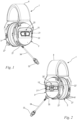
- a headset 1 according to the invention is shown.
- the headset 1 serves, among other things, as hearing protection when working with correspondingly high noise emissions. This includes, for example, working with motor chain saws, brush cutters, trimmers, blowers, cut-off grinders, stone cutters and the like.
- the headset 1 comprises a first earpiece 2, a second earpiece 3 and a connecting element 4.
- the first earpiece 2 and the second earpiece 3 are connected to one another via the connecting element 4.
- the connecting element 4 is designed as an elastic bracket.
- the bracket is at least partially covered with a pad to increase the wearing comfort of the headset 1.
- the connecting element 4 can also be designed as a protective helmet or the like. In such an embodiment, the first earpiece 2 and the second earpiece 3 are held to the protective helmet via fastening elements.
- the first earpiece 2 and the second earpiece 3 each comprise a loudspeaker (not shown), with the loudspeaker being arranged in each of the earpieces 2, 3.
- the headset 1 also comprises a microphone 33 which is attached to one of the two earpieces 2, 3 via a retaining bracket 34.
- the retaining bracket 34 is preferably attached to the second earpiece 3. However, it may also be expedient to attach the retaining bracket 34 with microphone 33 to the first earpiece 2.
- both earpieces 2, 3 have receptacles 35 for the retaining bracket 34 so that the operator can attach the retaining bracket 34 either to the first earpiece 2 or to the second earpiece 3.
- the retaining bracket 34 is designed in such a way that it holds the microphone 33 closer to the operator's mouth when the operator wears the headset 1 as intended.
- the first earpiece 2 and the second earpiece 3 each have an outer side 6, 6' and an inner side 5, 5'.
- the inner sides 5, 5' of the earpieces 2, 3 face each other, the outer sides 6, 6' of the earpieces 2, 3 face away from each other.
- the earpieces 2, 3 each extend from their inner side 5, 5' to the outer side 6, 6' in a first transverse direction 31.
- the earpiece 2, 3 in the embodiment is in the direction of the Figures 4 and 5 , i.e. in the direction of view of the first transverse direction 31, is approximately oval-shaped. Other shapes of the earpiece 2, 3 can also be useful.
- Individual sides are to be assigned to the earpiece 2, 3 as follows: As in Fig.3 shown, the earpieces 2, 3 extend from their bottom side 7, 7' to the top side 8, 8' in a vertical direction 30.
- the top side 8, 8' is the side of the earpiece 2, 3 facing away from the retaining bracket 34, the bottom side 7, 7' is the side of the earpiece 2, 3 facing the retaining bracket 34.
- the earpieces 2, 3 extend from a first longitudinal side 9, 9' to the second longitudinal side 10, 10' in a second transverse direction 32.
- the first longitudinal side 9, 9' of the earpiece 2, 3 is the side facing the microphone 33
- the second longitudinal side 10, 10' of the earpiece 2, 3 is the side facing away from the microphone 33.
- the first transverse direction 31, the second transverse direction 32 and the vertical direction 30 of the headset 1 are each aligned perpendicular to one another.
- the first transverse direction 31, the second transverse direction 32 and the vertical direction 30 thus correspond to a straight, orthogonal coordinate system (Cartesian coordinate system), at least with regard to their alignment.
- both earpieces 2, 3 each comprise a positioning pocket 15, 15' for easy positioning of the operator's hand. It can also be expedient for only the first earpiece 2 or the second earpiece 3 to comprise a positioning pocket 15, 15'.
- the positioning pocket 15, 15' is arranged on the outside 6, 6' of the earpiece 2, 3.
- At least one button 22, 22' is arranged in the positioning pocket 15, 15'.
- the positioning pocket 15, 15' comprises a stop edge 20, 20'.
- the stop edge 20, 20' extends in the second transverse direction 32.
- the stop edge 20, 20' is designed such that the fingertips contact the stop edge 20, 20' when inserted into the positioning pocket 15, 15' in the vertical direction 30 and strike against it.
- the positioning pocket 15, 15' also comprises a first side wall 18, 18' and a second side wall 19, 19'.
- the side walls 18, 18', 19, 19' extend approximately in the vertical direction 30.
- the first side wall 18, 18' and the second side wall 19, 19' each have a first end 36 facing the top side 8, 8' of the earpiece 2, 3.
- the first side wall 18, 18' and the second side wall 19, 19' are connected to one another via the stop edge 20, 20'.
- the stop edge 20, 20' adjoins the first ends 36 of the two side walls 18, 18', 19, 19'.
- the side walls 18, 18', 19, 19' form a guide 21, 21' for the operator's fingers in the vertical direction 30.
- the guide 21, 21' positions the fingers in the second transverse direction 32. In addition, slipping of the fingers in the second transverse direction 32 is prevented.
- the positioning pocket 15, 15' has a width a which corresponds to the distance between the two side walls 18, 18', 19, 19' measured in the second transverse direction 32.
- the earpiece 2, 3 has a width b which corresponds to the maximum distance between the first long side 9, 9' and the second long side 10, 10' of the earpiece 2, 3 measured in the second transverse direction 32.
- the width a of the positioning pocket 15 is at least 50%, in particular at least 60%, preferably approximately 75% of the width b of the earpiece 2, 3.
- the positioning pocket 15, 15' has a height d which corresponds to the distance measured in the vertical direction 30 between a lower end 16, 16' and an upper end 17, 17' of the positioning pocket 15.
- the upper end 17, 17' of the positioning pocket 15, 15' is formed by the stop edge 20, 20' of the positioning pocket 15, 15'.
- the lower end 16, 16' of the positioning pocket 15, 15' is the section of the earpiece 2, 3 in which the positioning pocket 15, 15' merges into a base area 11, 11' of the earpiece 2, 3 forming the outer side 6, 6'.
- this section is formed by a stepless edge 38, 38' between a bottom surface 39, 39' of the positioning pocket 15, 15' and the base surface 11, 11' of the earpiece 2, 3. It may also be expedient to provide a smooth transition between the bottom surface 39, 39' of the positioning pocket 15, 15' and the base surface 11, 11' of the earpiece 2, 3 instead of the edge 38, 38'.
- the lower end 16, 16' of the positioning pocket 15, 15' is also formed by the second ends 37 of the side walls 18, 18', 19, 19' of the positioning pocket 15, 15' facing the underside 7, 7' of the earpiece 2, 3.
- the earpiece 2, 3 has a height e which corresponds to the maximum distance measured in the vertical direction 30 between the underside 7, 7' and the top 8, 8' of the earpiece 2, 3.
- the height d of the positioning pocket 15, 15' is at least 15%, in particular at least 25%, preferably approximately 30% of the height e of the earpiece 2, 3.
- the bottom surface 39, 39' of the positioning pocket 15, 15' is slightly convexly curved.
- an approximate plane 40 is shown which approximates the bottom surface 39, 39' of the positioning pocket 15, 15'.
- the approximate plane 40 encloses an angle ⁇ with the inner side 5, 5' of the earpiece 2, 3, which is open towards the underside 7, 7' of the earpiece 2, 3.
- the angle ⁇ is at least 5°, in particular approximately 7°.
- the stop edge 20, 20' has a depth f which corresponds to the maximum distance measured in the first transverse direction 31 between the base surface 11 of the earpiece 2, 3 and the bottom surface 39, 39' of the positioning pocket 15, 15'.
- the earpiece 2, 3 has a depth c ( Fig.3 ) which corresponds to the maximum distance measured in the first transverse direction 31 between the inner side 5, 5' and the outer side 6, 6' of the earpiece 2, 3.
- the depth f of the stop edge 20, 20' is at least 5% of the depth c of the earpiece 2, 3.
- the headset 1 further comprises a control interface (not shown) in order to be able to control various devices via the headset 1 or to be able to carry out functions of the headset 1.
- the headset 1 can be connected to a computer unit, in particular to a smartphone, a tablet, a notebook or the like, via the control interface.
- the exemplary embodiment of the headset 1 also comprises a radio, a music player and/or the like. In the preferred embodiment, the headset 1 is designed to be connected to a radio device.
- the button 22 is designed as a connection button 23.
- the connection button 23 enables the operator to connect the headset 1 to the computer unit, in particular to a smartphone, tablet, notebook or the like.
- the radio can preferably also be activated via the connection button 23. If the headset 1 is connected to the computer unit, calls can preferably be received and ended via the connection button 23 and voice assistants can be activated to operate other applications. It can be advantageous to assign additional functions to the connection button 23.
- the connection button 23 comprises a width g measured in the second transverse direction 32, which corresponds to at least 50%, in particular at least 60%, preferably approximately 75% of the width a of the positioning pocket 15, 15'. Furthermore, the width g of the connection button 23 corresponds to at least 25%, preferably at least 35%, in particular at least 45% of the width b of the earpiece 2, 3.
- the connection button 23 comprises a height h measured in the vertical direction 30, which corresponds to at least 30%, in particular at least 40%, preferably approximately 50% of the height d of the positioning pocket 15, 15'.
- the connection button 23 comprises a raised collar 29 that runs around the connection button 23. The collar 29 enables the connection button 23 to be easily felt.
- the first earpiece 2 comprises a side button 27.
- the side button 27 of the first earpiece 2 is arranged between the underside 7 of the first earpiece 2 and the second long side 10 of the earpiece 2.
- Three knob-like elevations 41 are attached to the side button 27 of the first earpiece 2. In the exemplary embodiment, the elevations are arranged in a row. The knob-like elevations 41 enable the operator to easily identify the side button 27.
- the microphone 33 can be activated and deactivated via the side button 27 of the first earpiece 2.
- group communication with other Operators who wear such a headset 1 can activate and deactivate it by switching the microphone 33.
- the side button 27 is arranged with the positioning pocket 15 and the corresponding connection button 23 in such a way that after placing the operator's hand in the basic position, the operator can press the connection button 23 with his index finger, middle finger and/or ring finger and the side button 27 with his thumb. The hand does not have to be moved. This ensures ergonomic operation of the first earpiece 2. The operator's hand is then in the basic position when the operator's fingertips are approximately on the stop edge 20, 20' of the positioning pocket 15, 15'.
- buttons 24, 25, 26 are arranged in the positioning pocket 15' of the second earpiece 3.
- the three buttons 24, 25, 26 are a first button 24, a second button 25 and a third button 26.
- the three buttons 24, 25, 26 are arranged next to one another in the second transverse direction 32. This allows the operator to place a finger on each of the three buttons 24, 25, 26 in the basic position of his hand, which simplifies the operation of the buttons 24, 25, 26.
- the second button 25 is arranged between the first button 24 and the third button 26. In an alternative embodiment, it may also be expedient to provide a different number of buttons in the positioning pocket 15'.
- the second button 25 is offset from the first button 24 and the third button 26 in the first transverse direction 31, in particular is arranged higher.
- the second button 25 is separated from the first button 24 and the third button 26 by a dividing bar 28.
- the dividing bar 28 allows the operator to easily distinguish the three buttons 24, 25, 26 from one another in their spatial arrangement by touch.
- the first button 24 and the third button 26 are at least partially surrounded on their circumference by a raised collar 29.
- the collar 29 of the first button 24 and the third button 26 each adjoins the dividing bar 28.
- the collar 29 of the first button 24 and the third button 26 allows the operator to easily identify the buttons.
- the volume of the loudspeakers in the two earpieces 2, 3 can preferably be adjusted using the first button 24 and the third button 26.
- the radio can be activated and deactivated using the third button 26.
- the headset 1 can be switched on using the second button 25.
- the headset 1 can preferably also be coupled to the computer unit, i.e. a smartphone and the like, using the second button 25.
- the second button 25 in the exemplary embodiment is preferably also used for navigation when playing music and for selecting stations when using the radio.
- the second earpiece 3 comprises a side button 27 ⁇ .
- the side button 27' of the second earpiece 3 is arranged between the underside 7' of the second earpiece 3 and the first long side 9' of the second earpiece 3.
- the side button 27' has a circular basic shape in the embodiment ( Fig.1 ). Because the side button 27 of the first earpiece 2 and the side button 27' of the second earpiece 3 are designed differently, both side buttons 27, 27' are easy for the user to distinguish.
- the side button 27' is designed as a communication-related function button, in particular a push-to-talk button or a mute button.
- the side button 27' of the second earpiece 3 and the buttons 24, 25, 26 in the positioning pocket 15' are arranged such that the three buttons 24, 25, 26 and the side button 27 can be operated from the basic position of the operator's hand.
- the first button 24 can be operated using the ring finger, the second button 25 using the middle finger, the third button 26 using the index finger and the side button 27' using the thumb. All buttons can thus be operated from the basic position of the hand without having to reposition the hand.
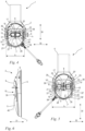
- the headset 1 according to the invention is shown in a partial side view of the first earpiece 2.
- the first earpiece 2 has a first center of gravity 42 when viewed along the first transverse direction 31 towards the outside 6.
- the first center of gravity 42 is arranged in the exemplary embodiment, in particular approximately centrally, in the positioning pocket 15.
- the first center of gravity 42 is arranged in the exemplary embodiment, in particular approximately centrally, in the at least one button 22.
- the side button 27 of the earpiece 2 has a second center of gravity 43 when viewed along the first transverse direction 31 towards the outside 6.
- the first center of gravity 42 of the first earpiece 2 and the second center of gravity 43 of the side button 27 have a distance i measured in the vertical direction 30, the distance i corresponding to at least 20%, in particular at least 30%, preferably approximately 35% of the height e of the earpiece 2.
- the first center of gravity 42 of the first earpiece 2 and the second center of gravity 43 of the side button 27 have a distance j measured in the second transverse direction 32, wherein the distance j corresponds to at least 20%, in particular at least 30%, preferably approximately 35% of the width b of the earpiece 2.
- a longitudinal straight line 45 oriented in the vertical direction 30 runs through the first surface center 42 of the earpiece 2.
- a connecting straight line 44 is shown, which runs through the first surface point 42 and through the second surface point 43 and at the same time intersects the longitudinal straight line 45.
- the longitudinal line 45 and the connecting line 44 form an angle ⁇ , with the angle ⁇ being open towards the underside 7 of the first earpiece 2.
- the angle ⁇ is in a range from 15° to 60°, preferably from 25° to 45°.
- the angle ⁇ is preferably approximately 35°.
- the first earpiece 2 and the second earpiece 3 are essentially mirror-symmetrical in their basic shape with respect to a plane spanned by the vertical direction 30 and the second transverse direction 32. Therefore, the relationships described above regarding the arrangement of the side button 27 to the center of gravity 42 of the first earpiece 2 also apply to the second earpiece 3.
Landscapes
- Engineering & Computer Science (AREA)
- Acoustics & Sound (AREA)
- Physics & Mathematics (AREA)
- Signal Processing (AREA)
- Health & Medical Sciences (AREA)
- Life Sciences & Earth Sciences (AREA)
- Vascular Medicine (AREA)
- Biophysics (AREA)
- Otolaryngology (AREA)
- Psychology (AREA)
- Biomedical Technology (AREA)
- Heart & Thoracic Surgery (AREA)
- Animal Behavior & Ethology (AREA)
- General Health & Medical Sciences (AREA)
- Public Health (AREA)
- Veterinary Medicine (AREA)
- Manufacturing & Machinery (AREA)
- Telephone Set Structure (AREA)
Description
- Die Erfindung betrifft ein Headset gemäß dem Oberbegriff des Anspruchs 1.
- Aus der
EP 3 451 689 A1 ist ein Headset bekannt, das zwei Hörmuscheln umfasst, wobei die Hörmuscheln über einen Tragbügel miteinander verbunden sind. Das Headset ist derart ausgebildet, dass der Bediener diese mittels des Tragbügels auf seinen Kopf klemmen kann und die Ohren des Bedieners durch die Hörmuscheln verdeckt sind. Zum einen dienen die Hörmuscheln als Gehörschutz, zum anderen sind in den Hörmuscheln Lautsprecher vorgesehen, um über eine Steuerschnittstelle Information an den Bediener zu übertragen. An den Hörmuscheln sind mehrere Tasten vorgesehen, die die Bedienung der Steuerschnittstelle ermöglichen. - Nachteilig an derartigen Headsets ist, dass die Tasten nur schwer auffindbar sind, wodurch die Bedienung der Steuerschnittstelle erschwert ist. Derartige Headsets sind insbesondere für Arbeiten im Freien vorgesehen, beispielsweise Waldarbeiten, Gartenarbeiten oder dgl., bei welchen der Bediener zumeist Arbeitshandschuhe trägt. Dieser Umstand erschwert zusätzlich das zielgerichtete Drücken der entsprechenden Tasten.
- Die folgenden im Internet zugänglichen Dokumente offenbaren Headsets bei welchen mindestens ein Bedienelement in einer Vertiefung angeordnet ist:
- "HUSQVARNA ZUBEHÖR UND BEKLEIDUNG Katalog 2011 - Gehörschutz", 7. März 2011, XP055789824, URL:https://issuu.com/husqvarna/docs/husqvarna_acc_2011_de [gefunden am 2021-03-25], sowie
- "Husqvarna-X-Com-R Hearing Protector Manual", 5. Juli 2019, XP055789837, URL:https:// www.manualslib.de/download/575441/Husqvarna-X-Com-R-Hp310-1.html [gefunden am 2021-03-25].
- Demnach liegt der Erfindung die Aufgabe zugrunde, ein Headset der gattungsgemäßen Art derart weiterzuentwickeln, dass eine einfache Bedienung des Headsets ermöglicht ist.
- Diese Aufgabe wird durch ein Headset mit den Merkmalen des Anspruchs 1 gelöst.
- Das Headset umfasst eine erste Hörmuschel und eine zweite Hörmuschel, wobei die erste Hörmuschel und die zweite Hörmuschel über ein Verbindungselement miteinander verbunden sind. Die Hörmuscheln weisen jeweils eine Innenseite und eine Außenseite auf, wobei die Innenseiten der Hörmuscheln einander zugewandt und die Außenseiten der Hörmuscheln einander abgewandt sind. Die Hörmuscheln erstrecken sich jeweils von ihrer Unterseite zu ihrer Oberseite in eine Hochrichtung und von ihrer ersten Längsseite zu ihrer zweiten Längsseite in eine zweite Querrichtung. Die erste Hörmuschel und/oder die zweite Hörmuschel weist an ihrer Außenseite eine Positioniertasche mit mindestens einer Taste auf, wobei sich die Positioniertasche über eine Breite in die zweite Querrichtung der Hörmuschel erstreckt, wobei die Breite der Positioniertasche mindestens 50% der in zweiter Querrichtung gemessenen Breite der Hörmuschel entspricht. Die Positioniertasche erstreckt sich in Hochrichtung der Hörmuschel von einem unteren Ende zu einem oberen Ende. Das obere Ende der Positioniertasche ist durch eine Anschlagkante zur Anlage der Fingerspitzen eines Bedieners ausgebildet.
- Die Anschlagkante der Positioniertasche kann der Bediener auf einfache Weise ertasten. Das Headset ist dabei so ausgebildet, dass der Bediener seine Hand in die Positioniertasche rutschen lassen kann bis die Fingerspitzen des Bedieners an der Anschlagkante der Positioniertasche zur Anlage kommen. Liegen die Fingerspitzen des Bedieners in etwa an der Anschlagkante der Positioniertasche an, befindet sich die Hand in einer Grundstellung. Hierzu kann der Bediener seine Hand auf der Außenseite nahe der Unterseite der Hörmuschel positionieren und anschließend seine Hand in Hochrichtung zur Oberseite der Hörmuschel schieben, bis die Fingerspitzen die Anschlagkante der Positioniertasche kontaktieren. Dadurch kann die Hand des Bedieners auf einfache Weise immer wieder in die Grundstellung gebracht werden, von welcher aus die mindestens eine Taste in der Positioniertasche betätigt werden kann. Die Anschlagkante der Positioniertasche bildet somit ein einfach ertastbares Orientierungselement, wodurch die Bedienung des Headsets ohne Sichtkontakt mit dem Headset möglich ist.
- Es ist vorzugsweise vorgesehen, dass die Anschlagkante eine in einer ersten Querrichtung von der Innenseite zur Außenseite der Hörmuschel gemessene Tiefe aufweist, wobei die Tiefe der Anschlagkante mindestens 5% der in erster Querrichtung gemessenen Tiefe der Hörmuschel entspricht. Diese Ausgestaltung der Anschlagkante ermöglicht ein noch einfacheres Ertasten der Anschlagkante. So ist es beispielsweise dem Bediener auch mit Handschuhen möglich, seine Hand durch Ertasten der Anschlagkante in die Grundstellung zu positionieren.
- Die Positioniertasche geht an ihrem unteren Ende vorzugsweise absatzlos in eine die Außenseite der Hörmuschel bildende Grundfläche über. Durch den absatzlosen Übergang zwischen der Grundfläche der Hörmuschel und der Positioniertasche kann die Hand des Bedieners über die Grundfläche in die Positioniertasche geschoben werden.
- Es ist vorteilhaft vorgesehen, dass die Positioniertasche in zweiter Querrichtung der Hörmuschel durch eine erste Seitenwand und eine zweite Seitenwand begrenzt ist, wobei die beiden Seitenwände eine Führung in Querrichtung der Hörmuschel zur seitlichen Führung der Finger des Bedieners bilden. Die erste Seitenwand und die zweite Seitenwand der Positioniertasche bilden Anschläge für die Finger des Bedieners in zweiter Querrichtung. Bereits beim Einschieben der Finger in die Positioniertasche werden diese durch die Seitenwände in Hochrichtung geführt. Befindet sich die Hand des Bedieners in Grundstellung, ist die Hand auf der Hörmuschel durch die Anschlagkante der Positioniertasche in Hochrichtung und durch die Seitenwände in zweiter Querrichtung ausgerichtet.
- Es ist vorzugsweise vorgesehen, dass in der Positioniertasche der ersten Hörmuschel lediglich eine Verbindungstaste angeordnet ist, die sich über mindestens 50% der Breite der Positioniertasche erstreckt. Demnach ist die mindestens eine Taste der ersten Hörmuschel als Verbindungstaste ausgebildet. Durch die breite Ausgestaltung der Verbindungstaste kann diese durch den Bediener auf einfache Weise ertastet und betätigt werden. Die Verbindungstaste ist vorzugsweise zur Verbindung mit einer Rechnereinheit, insbesondere einem Smartphone, ausgebildet.
- Es ist vorzugsweise vorgesehen, dass in der Positioniertasche der zweiten Hörmuschel mindestens zwei Tasten, insbesondere drei Tasten, angeordnet sind. Vorteilhaft sind die mindestens zwei Tasten respektive die mindestens drei Tasten durch einen Trennsteg voneinander getrennt. Dadurch kann der Bediener die Tasten auf einfache Weise voneinander unterscheiden. Vorzugsweise ist eine der mindestens zwei Tasten gegenüber der anderen Taste vertieft in Richtung zur Innenseite der Hörmuschel in der Positioniertasche angeordnet. Auch der Tiefenversatz der Tasten zueinander ermöglicht dem Bediener eine einfache Unterscheidung der Tasten. Vorteilhaft weist die mindestens eine Taste einen zumindest teilweise die Taste umlaufenden Kragen auf.
- Es ist gemäß dem Anspruch 1 vorgesehen, dass an der ersten Hörmuschel und/oder an der zweiten Hörmuschel außerhalb der Positioniertasche eine Seitentaste angeordnet ist, wobei die Seitentaste und die Positioniertasche derart zueinander angeordnet sind, dass in einer Grundstellung der Hand des Bedieners die mindestens eine Taste in der Positioniertasche und die Seitentaste betätigbar sind, ohne die Hand neu positionieren zu müssen. Vorzugsweise sind in der Grundstellung der Hand des Bedieners drei Tasten in der Positioniertasche und die Seitentaste betätigbar, ohne die Hand neu positionieren zu müssen. Dadurch ist eine besonders ergonomische Bedienung des Headsets möglich.
- Zudem ist gemäß dem Anspruch 1 die Seitentaste zwischen der Unterseite der Hörmuschel und der zweiten Längsseite der Hörmuschel angeordnet. Dadurch lässt sich die Seitentaste mit dem Daumen auf einfache Weise betätigen.
- Es ist vorteilhaft vorgesehen, dass in Blickrichtung entlang der ersten Querrichtung auf die Außenseite die Hörmuschel einen ersten Flächenschwerpunkt und die Seitentaste einen zweiten Flächenschwerpunkt aufweist, wobei der in Hochrichtung gemessene Abstand zwischen dem ersten Flächenschwerpunkt und dem zweiten Flächenschwerpunkt mindestens 20%, insbesondere mindestens 30%, vorzugsweise in etwa 35% der Höhe der Hörmuschel entspricht. Der erste Flächenschwerpunkt der Hörmuschel liegt vorzugsweise auf der Positioniertasche, insbesondere auf der mindestens einen Taste. Durch den Abstand zwischen den zwei Flächenschwerpunkten wird eine ergonomische Anordnung der Seitentaste zu der mindestens einen Taste in der Positioniertasche gewährleistet. Dies ermöglicht dem Bediener, in der Grundstellung der Hand die mindestens eine Taste mit dem Zeigefinger, Mittelfinger und/oder dem Ringfinger betätigen zu können, und zudem in der Grundstellung auf komfortable Weise mit dem Daumen auch die Seitentaste betätigen zu können.
- Vorteilhaft weist die Seitentaste der ersten Hörmuschel drei noppenartige Erhöhungen auf. Dadurch lässt sich die Seitentaste der ersten Hörmuschel von der Seitentaste der zweiten Hörmuschel unterscheiden.
- Vorzugsweise ist die Seitentaste der zweiten Hörmuschel als eine kreisförmige Funktions-Taste, insbesondere als eine push-to-talk-Taste oder eine Stummschaltungs-Taste, ausgebildet. Mit Betätigung der Seitentaste der ersten Hörmuschel oder der Seitentaste der zweiten Hörmuschel kann eine kommunikationsbezogene Funktion aktiviert oder deaktiviert werden, insbesondere eine push-to-talk Funktion für ein mit dem Headset verbindbares Funkgerät oder eine Funktion für eine Gruppenkommunikation oder eine Mikrofon-Stummschaltung.
- Weitere Merkmale der Erfindung ergeben sich aus der Beschreibung und der Zeichnung, in der ein nachfolgend im Einzelnen beschriebenes Ausführungsbeispiel der Erfindung dargestellt ist. Es zeigen:
- Fig. 1
- in perspektivischer Darstellung auf die erste Hörmuschel ein erfindungsgemäßes Headset,
- Fig. 2
- in perspektivischer Darstellung auf die zweite Hörmuschel das Headset nach
Fig. 1 , - Fig. 3
- in Vorderansicht das Headset nach
Fig. 1 , - Fig. 4
- in Seitenansicht auf die erste Hörmuschel das Headset nach
Fig. 1 , - Fig. 5
- in Seitenansicht auf die zweite Hörmuschel das Headset nach
Fig. 1 , - Fig. 6
- in Seitenansicht eine ausschnittsweise, schematische Darstellung der ersten Hörmuschel ohne Taste und
- Fig. 7
- in ausschnittsweiser Seitenansicht auf die erste Hörmuschel das Headset nach
Fig. 1 . - In
Fig. 1 ist ein erfindungsgemäßes Headset 1 gezeigt. Das Headset 1 dient unter anderem als Gehörschutz bei Arbeiten mit entsprechend hohen Geräuschemissionen. Hierzu zählen beispielsweise Arbeiten mit Motorkettensägen, Freischneidern, Trimmern, Blasgeräten, Trennschleifern, Gesteinsschneidern und dgl. Das Headset 1 umfasst eine erste Hörmuschel 2, eine zweite Hörmuschel 3 und ein Verbindungselement 4. Die erste Hörmuschel 2 und die zweite Hörmuschel 3 sind über das Verbindungselement 4 miteinander verbunden. In dem vorliegenden Ausführungsbeispiel ist das Verbindungselement 4 als ein elastischer Bügel ausgebildet. Der Bügel ist zumindest teilweise mit einem Polster zur Erhöhung des Tragekomforts des Headsets 1 umkleidet. In einer alternativen, nicht dargestellten Ausführung des Headsets 1 kann das Verbindungselement 4 auch als ein Schutzhelm oder dgl. ausgebildet sein. In einer solchen Ausführung sind die erste Hörmuschel 2 und die zweite Hörmuschel 3 über Befestigungselemente an dem Schutzhelm gehalten. - Die erste Hörmuschel 2 sowie die zweite Hörmuschel 3 umfassen jeweils einen nicht dargestellten Lautsprecher, wobei der Lautsprecher jeweils in den Hörmuscheln 2, 3 angeordnet ist. Zudem umfasst das Headset 1 ein Mikrofon 33, das über einen Haltebügel 34 an einer der beiden Hörmuscheln 2, 3 befestigt ist. Der Haltebügel 34 ist vorzugsweise an der zweiten Hörmuschel 3 befestigt. Es kann jedoch auch zweckmäßig sein, den Haltebügel 34 mit Mikrofon 33 an der ersten Hörmuschel 2 zu befestigen. Vorzugsweise sind an beiden Hörmuscheln 2, 3 Aufnahmen 35 für den Haltebügel 34 vorgesehen, so dass der Bediener den Haltebügel 34 entweder an der ersten Hörmuschel 2 oder an der zweiten Hörmuschel 3 befestigen kann. Der Haltebügel 34 ist derart gestaltet, dass dieser das Mikrofon 33 näher an den Mund des Bedieners hält, wenn der Bediener das Headset 1 wie vorgesehen trägt.
- Wie in
Fig. 3 gezeigt, weisen die erste Hörmuschel 2 und die zweite Hörmuschel 3 jeweils eine Außenseite 6, 6' und jeweils eine Innenseite 5, 5' auf. Die Innenseiten 5, 5' der Hörmuscheln 2, 3 sind einander zugewandt, die Außenseiten 6, 6' der Hörmuscheln 2, 3 sind einander abgewandt. Die Hörmuscheln 2, 3 erstrecken sich jeweils von ihrer Innenseite 5, 5' zur Außenseite 6, 6' in eine erste Querrichtung 31. - Wie in den
Figuren 4 und 5 gezeigt, ist die Hörmuschel 2, 3 im Ausführungsbeispiel in Blickrichtung derFiguren 4 und 5 , also in Blickrichtung der ersten Querrichtung 31, in etwa ovalförmig ausgebildet. Auch andere Formen der Hörmuschel 2, 3 können zweckmäßig sein. Der Hörmuschel 2, 3 sind wie folgt einzelne Seiten zuzuweisen:
Wie inFig. 3 gezeigt, erstrecken sich die Hörmuscheln 2, 3 von ihrer Unterseite 7, 7' zur Oberseite 8, 8' in eine Hochrichtung 30. Die Oberseite 8, 8' ist die dem Haltebügel 34 abgewandte Seite der Hörmuschel 2, 3, die Unterseite 7, 7' ist die dem Haltebügel 34 zugewandte Seite der Hörmuschel 2, 3. Wie in denFiguren 4 und 5 gezeigt, erstecken sich die Hörmuscheln 2, 3 von einer ersten Längsseite 9, 9' zur zweiten Längsseite 10, 10' in eine zweite Querrichtung 32. Die erste Längsseite 9, 9' der Hörmuschel 2, 3 ist die dem Mikrofon 33 zugewandte Seite, die zweite Längsseite 10, 10' der Hörmuschel 2, 3 ist die dem Mikrofon 33 abgewandte Seite. Im Ausführungsbeispiel sind die erste Querrichtung 31, die zweite Querrichtung 32 und die Hochrichtung 30 des Headsets 1 jeweils senkrecht zueinander ausgerichtet. Damit entsprechen die erste Querrichtung 31, die zweite Querrichtung 32 und die Hochrichtung 30 zumindest im Hinblick auf deren Ausrichtung einem geradlinigen, orthogonalen Koordinatensystem (kartesisches Koordinatensystem). - Wie in den
Figuren 1 und 2 gezeigt, umfassen im erfindungsgemäßen Ausführungsbeispiel des Headsets 1 beide Hörmuscheln 2, 3 jeweils eine Positioniertasche 15, 15' zur einfachen Positionierung der Hand des Bedieners. Es kann auch zweckmäßig sein, dass lediglich die erste Hörmuschel 2 oder die zweite Hörmuschel 3 eine Positioniertasche 15, 15' umfasst. Die Positioniertasche 15, 15' ist auf der Außenseite 6, 6' der Hörmuschel 2, 3 angeordnet. In der Positioniertasche 15, 15' ist mindestens eine Taste 22, 22' angeordnet. - Wie in den
Figuren 4 und 5 gezeigt, umfasst die Positioniertasche 15, 15' eine Anschlagkante 20, 20'. Die Anschlagkante 20, 20' erstreckt sich in die zweite Querrichtung 32. Die Anschlagkante 20, 20' ist derart ausgebildet, dass die Fingerspitzen beim Einführen in die Positioniertasche 15, 15' in Hochrichtung 30 die Anschlagkante 20, 20' kontaktieren und an dieser anschlagen. Ferner umfasst die Positioniertasche 15, 15' eine erste Seitenwand 18, 18' und eine zweite Seitenwand 19, 19'. Die Seitenwände 18, 18', 19, 19' erstrecken sich in etwa in Hochrichtung 30. Die erste Seitenwand 18, 18' und die zweite Seitenwand 19, 19' weisen jeweils ein der Oberseite 8, 8' der Hörmuschel 2, 3 zugewandtes erstes Ende 36 auf. Die erste Seitenwand 18, 18' und die zweite Seitenwand 19, 19' sind über die Anschlagkante 20, 20' miteinander verbunden. Die Anschlagkante 20, 20' schließt an den ersten Enden 36 der beiden Seitenwände 18, 18', 19, 19' an. Die Seitenwände 18, 18', 19, 19' bilden eine Führung 21, 21' für die Finger des Bedieners in Hochrichtung 30. Durch die Führung 21, 21' sind die Finger in zweiter Querrichtung 32 positioniert. Zudem wird ein Abrutschen der Finger in zweiter Querrichtung 32 vermieden. - Wie in den
Figuren 4 und 5 gezeigt, besitzt die Positioniertasche 15, 15' eine Breite a, die dem in zweiter Querrichtung 32 gemessenen Abstand der beiden Seitenwände 18, 18', 19, 19' entspricht. Die Hörmuschel 2, 3 besitzt eine Breite b, die dem in zweiter Querrichtung 32 gemessenen maximalen Abstand zwischen der ersten Längsseite 9, 9' und der zweiten Längsseite 10, 10' der Hörmuschel 2, 3 entspricht. Die Breite a der Positioniertasche 15 beträgt mindestens 50%, insbesondere mindestens 60%, vorzugsweise in etwa 75% der Breite b der Hörmuschel 2, 3. - Wie in den
Figuren 4 und 5 gezeigt, umfasst die Positioniertasche 15, 15' eine Höhe d, die dem in Hochrichtung 30 gemessenen Abstand zwischen einem unteren Ende 16, 16' und einem oberen Ende 17, 17' der Positioniertasche 15 entspricht. Das obere Ende 17, 17' der Positioniertasche 15, 15' ist durch die Anschlagkante 20, 20' der Positioniertasche 15, 15' gebildet. Das untere Ende 16, 16' der Positioniertasche 15, 15' ist der Abschnitt der Hörmuschel 2, 3, in dem die Positioniertasche 15, 15' in eine die Außenseite 6, 6' bildende Grundfläche 11, 11' der Hörmuschel 2, 3 übergeht. Im vorliegenden Ausführungsbeispiel ist dieser Abschnitt durch eine absatzlose Kante 38, 38' zwischen einer Bodenfläche 39, 39' der Positioniertasche 15, 15' und der Grundfläche 11, 11' der Hörmuschel 2, 3 gebildet. Es kann auch zweckmäßig sein, anstelle der Kante 38, 38' einen fließenden Übergang zwischen der Bodenfläche 39, 39' der Positioniertasche 15, 15' und der Grundfläche 11, 11' der Hörmuschel 2, 3 vorzusehen. Zudem ist im Ausführungsbeispiel das untere Ende 16, 16' der Positioniertasche 15, 15' auch durch die der Unterseite 7, 7' der Hörmuschel 2, 3 zugewandten zweiten Enden 37 der Seitenwände 18, 18', 19, 19' der Positioniertasche 15, 15' gebildet. Die Hörmuschel 2, 3 besitzt eine Höhe e, die dem in Hochrichtung 30 gemessenen maximalen Abstand zwischen der Unterseite 7, 7' und der Oberseite 8, 8' der Hörmuschel 2, 3 entspricht. Die Höhe d der Positioniertasche 15, 15' beträgt mindestens 15%, insbesondere mindestens 25%, vorzugsweise in etwa 30% der Höhe e der Hörmuschel 2, 3. - Im Ausführungsbeispiel ist die Bodenfläche 39, 39' der Positioniertasche 15, 15' leicht konvex gekrümmt ausgebildet. Wie in
Fig. 6 schematisch dargestellt, ist eine an die Bodenfläche 39, 39' der Positioniertasche 15, 15' angenäherte Näherungsebene 40 gezeigt. In der Seitenansicht der ersten Hörmuschel 2 nachFig. 6 wurde auf die Darstellung einer Taste 22 verzichtet, um die Bodenfläche 39 besser darstellen zu können. Die Näherungsebene 40 schließt mit der Innenseite 5, 5' der Hörmuschel 2, 3 einen Winkel α ein, der zur Unterseite 7, 7' der Hörmuschel 2, 3 hin geöffnet ist. Im Ausführungsbeispiel beträgt der Winkel α mindestens 5°, insbesondere in etwa 7°. Es kann in einer alternativen Ausführung auch zweckmäßig sein, die Bodenfläche 39, 39` bzw. deren Näherungsebene 40 und die Innenseite 5, 5' der Hörmuschel 2, 3 in etwa parallel zueinander auszurichten. - Wie in
Fig. 6 gezeigt, weist die Anschlagkante 20, 20' eine Tiefe f auf, die dem in erster Querrichtung 31 gemessenen maximalen Abstand zwischen der Grundfläche 11 der Hörmuschel 2, 3 und der Bodenfläche 39, 39' der Positioniertasche 15, 15' entspricht. Die Hörmuschel 2, 3 weist eine Tiefe c (Fig. 3 ) auf, die dem in erster Querrichtung 31 gemessenen maximalen Abstand zwischen der Innenseite 5, 5' und der Außenseite 6, 6' der Hörmuschel 2, 3 entspricht. Im Ausführungsbeispiel beträgt die Tiefe f der Anschlagkante 20, 20' mindestens 5% der Tiefe c der Hörmuschel 2, 3. - Das Headset 1 umfasst ferner eine nicht dargestellte Steuerschnittstelle, um verschiedene Gerätschaften über das Headset 1 ansteuern zu können oder Funktionen des Headsets 1 ausführen zu können. Über die Steuerschnittstelle ist das Headset 1 mit einer Rechnereinheit, insbesondere mit einem Smartphone, einem Tablet, einem Notebook oder dgl. verbindbar. Ferner umfasst das Ausführungsbeispiel des Headsets 1 ein Radio, einen Musikspieler und/oder dgl. In der bevorzugten Ausführungsform ist das Headset 1 zum Verbinden mit einem Funkgerät ausgebildet.
- Wie in
Fig. 4 gezeigt, ist in der Positioniertasche 15, 15' der ersten Hörmuschel 2, 3 lediglich eine Taste 22 angeordnet. Die Taste 22 ist als eine Verbindungstaste 23 ausgebildet. Die Verbindungstaste 23 ermöglicht es dem Bediener, das Headset 1 mit der Rechnereinheit, insbesondere mit einem Smartphone, Tablet, Notebook oder dgl. zu verbinden. Bevorzugt ist über die Verbindungstaste 23 auch das Radio aktivierbar. Ist das Headset 1 mit der Rechnereinheit verbunden, können vorzugsweise über die Verbindungstaste 23 Anrufe entgegengenommen und beendet werden und Sprachassistenten zur Bedienung weiterer Applikationen aktiviert werden. Es kann vorteilhaft sein, die Verbindungstaste 23 mit weiteren Funktionen zu belegen. - Wie in
Fig. 4 gezeigt, umfasst die Verbindungstaste 23 eine in zweiter Querrichtung 32 gemessene Breite g, die mindestens 50%, insbesondere mindestens 60%, vorzugsweise in etwa 75% der Breite a der Positioniertasche 15, 15' entspricht. Ferner entspricht die Breite g der Verbindungstaste 23 mindestens 25%, vorzugsweise mindestens 35%, insbesondere mindestens 45% der Breite b der Hörmuschel 2, 3. Die Verbindungstaste 23 umfasst eine in Hochrichtung 30 gemessene Höhe h, die mindestens 30%, insbesondere mindestens 40%, vorzugsweise in etwa 50% der Höhe d der Positioniertasche 15, 15' entspricht. Im Ausführungsbeispiel umfasst die Verbindungstaste 23 einen die Verbindungstaste 23 umlaufenden, hochgestellten Kragen 29. Der Kragen 29 ermöglicht ein einfaches Ertasten der Verbindungstaste 23. - Wie in
Fig. 4 gezeigt, umfasst die erste Hörmuschel 2 eine Seitentaste 27. Die Seitentaste 27 der ersten Hörmuschel 2 ist zwischen der Unterseite 7 der ersten Hörmuschel 2 und der zweiten Längsseite 10 der Hörmuschel 2 angeordnet. Auf der Seitentaste 27 der ersten Hörmuschel 2 sind drei noppenartige Erhöhungen 41 angebracht. Im Ausführungsbeispiel sind die Erhöhungen in einer Reihe angeordnet. Die noppenartigen Erhöhungen 41 ermöglichen es dem Bediener, die Seitentaste 27 auf einfache Weise zu erkennen. Im bevorzugten Ausführungsbeispiel des Headsets 1 kann über die Seitentaste 27 der ersten Hörmuschel 2 das Mikrofon 33 aktiviert und deaktiviert werden. Vorzugsweise kann auch eine Gruppenkommunikation mit anderen Bedienern, die ein solches Headset 1 tragen, durch Schalten des Mikrofons 33 aktiviert und deaktiviert werden. Die Seitentaste 27 ist mit der Positioniertasche 15 sowie der entsprechenden Verbindungstaste 23 derart angeordnet, dass nach Auflegen der Hand des Bedieners in die Grundstellung der Bediener die Verbindungstaste 23 mit seinem Zeigefinger, Mittelfinger und/oder Ringfinger und die Seitentaste 27 mit dem Daumen betätigen kann. Die Hand muss dabei nicht verschoben werden. Dadurch wird eine ergonomische Bedienung der ersten Hörmuschel 2 gewährleistet. Die Hand des Bedieners befindet sich dann in der Grundstellung, wenn die Fingerspitzen des Bedieners in etwa an der Anschlagkante 20, 20' der Positioniertasche 15, 15' anliegen. - Wie in
Fig. 5 gezeigt, sind in der Positioniertasche 15' der zweiten Hörmuschel 3 drei Tasten 24, 25, 26 angeordnet. Die drei Tasten 24, 25, 26 sind eine erste Taste 24, eine zweite Taste 25 und eine dritte Taste 26. Die drei Tasten 24, 25, 26 sind in der zweiten Querrichtung 32 nebeneinander angeordnet. Dadurch kann der Bediener in der Grundstellung seiner Hand auf jede der drei Tasten 24, 25, 26 einen Finger ablegen, wodurch die Bedienung der Tasten 24, 25, 26 vereinfacht ist. Die zweite Taste 25 ist zwischen der ersten Taste 24 und der dritten Taste 26 angeordnet. In einer alternativen Ausführung kann es auch zweckmäßig sein, eine andere Anzahl Tasten in der Positioniertasche 15' vorzusehen. Die zweite Taste 25 ist gegenüber der ersten Taste 24 und der dritten Taste 26 in erster Querrichtung 31 versetzt, insbesondere erhöht angeordnet. Die zweite Taste 25 ist jeweils durch einen Trennsteg 28 von der ersten Taste 24 und der dritten Taste 26 getrennt. Der Trennsteg 28 erlaubt dem Bediener, die drei Tasten 24, 25, 26 in ihrer räumlichen Anordnung haptisch auf einfache Weise voneinander unterscheiden zu können. Zudem sind die erste Taste 24 und die dritte Taste 26 an ihrem Umfang durch einen aufgestellten Kragen 29 zumindest teilweise umrandet. Der Kragen 29 der ersten Taste 24 und der dritten Taste 26 schließt jeweils an dem Trennsteg 28 an. Der Kragen 29 der ersten Taste 24 und der dritten Taste 26 ermöglicht dem Bediener eine einfache Erkennung der Tasten. - Im Ausführungsbeispiel ist über die erste Taste 24 und die dritte Taste 26 vorzugsweise die Lautstärke der Lautsprecher in den beiden Hörmuscheln 2, 3 einzustellen. Zudem kann mittels der dritten Taste 26 das Radio aktiviert und deaktiviert werden. Mittels der zweiten Taste 25 ist das Headset 1 einschaltbar. Vorzugsweise kann über die zweite Taste 25 das Headset 1 auch mit der Rechnereinheit, also einem Smartphone und dgl., gekoppelt werden. Ferner dient die zweite Taste 25 im Ausführungsbeispiel vorzugsweise auch zur Navigation bei der Musikwiedergabe sowie zur Senderwahl bei der Nutzung des Radios.
- Wie in
Fig. 5 gezeigt, umfasst die zweite Hörmuschel 3 eine Seitentaste 27`. Die Seitentaste 27' der zweiten Hörmuschel 3 ist zwischen der Unterseite 7' der zweiten Hörmuschel 3 und der ersten Längsseite 9' der zweiten Hörmuschel 3 angeordnet. Die Seitentaste 27' besitzt im Ausführungsbeispiel eine kreisrunde Grundform (Fig. 1 ). Dadurch, dass die Seitentaste 27 der ersten Hörmuschel 2 und die Seitentaste 27' der zweiten Hörmuschel 3 verschiedenartig ausgebildet sind, sind beide Seitentasten 27, 27' für den Bediener einfach zu unterscheiden. Im bevorzugten Ausführungsbeispiel des Headsets 1 ist die Seitentaste 27' als eine kommunikationsbezogene Funktions-Taste, insbesondere eine push-to-talk-Taste oder eine Stummschaltungs-Taste, ausgebildet. - Wie in
Fig. 5 gezeigt, sind die Seitentaste 27' der zweiten Hörmuschel 3 und die Tasten 24, 25, 26 in der Positioniertasche 15' derart angeordnet, dass aus der Grundstellung der Hand des Bedieners die drei Tasten 24, 25, 26 sowie die Seitentaste 27 betätigbar sind. Vorzugsweise ist in der Grundstellung der Hand die erste Taste 24 über den Ringfinger, die zweite Taste 25 über den Mittelfinger, die dritte Taste 26 über den Zeigefinger und die Seitentaste 27' über den Daumen betätigbar. Somit können aus der Grundstellung der Hand alle Tasten betätigt werden, ohne dabei die Hand neu positionieren zu müssen. - In
Fig. 7 ist das erfindungsgemäße Headset 1 in einer ausschnittsweisen Seitendarstellung auf die erste Hörmuschel 2 gezeigt. Die erste Hörmuschel 2 weist in Blickrichtung entlang der ersten Querrichtung 31 gerichtet auf die Außenseite 6 einen ersten Flächenschwerpunkt 42 auf. Der erste Flächenschwerpunkt 42 ist im Ausführungsbeispiel, insbesondere in etwa mittig, in der Positioniertasche 15 angeordnet. Der erste Flächenschwerpunkt 42 ist im Ausführungsbeispiel, insbesondere in etwa mittig, in der mindestens einen Taste 22 angeordnet. Die Seitentaste 27 der Hörmuschel 2 weist in Blickrichtung entlang der ersten Querrichtung 31 gerichtet auf die Außenseite 6 einen zweiten Flächenschwerpunkt 43 auf. Der erste Flächenschwerpunkt 42 der ersten Hörmuschel 2 und der zweite Flächenschwerpunkt 43 der Seitentaste 27 weisen einen in Hochrichtung 30 gemessenen Abstand i auf, wobei der Abstand i mindestens 20%, insbesondere mindestens 30%, vorzugsweise in etwa 35% der Höhe e der Hörmuschel 2 entspricht. Der erste Flächenschwerpunkt 42 der ersten Hörmuschel 2 und der zweite Flächenschwerpunkt 43 der Seitentaste 27 weisen einen in zweiter Querrichtung 32 gemessenen Abstand j auf, wobei der Abstand j mindestens 20%, insbesondere mindestens 30%, vorzugsweise in etwa 35% der Breite b der Hörmuschel 2 entspricht. Wie inFig. 7 gezeigt, verläuft durch den ersten Flächenschwerpunkt 42 der Hörmuschel 2 eine in Hochrichtung 30 ausgerichtete Längsgerade 45. Ferner ist eine Verbindungsgerade 44 gezeigt, die durch den ersten Flächenpunkt 42 und durch den zweiten Flächenpunkt 43 verläuft und zugleich die Längsgerade 45 schneidet. Wie inFig. 7 gezeigt, spannen die Längsgerade 45 und die Verbindungsgerade 44 einen Winkel β auf, wobei der Winkel β zur Unterseite 7 der ersten Hörmuschel 2 hin geöffnet ist. Der Winkel β liegt im Ausführungsbeispiel in einem Bereich von 15° bis 60°, vorzugsweise von 25° bis 45°. Der Winkel β beträgt vorzugsweise in etwa 35°. - Die erste Hörmuschel 2 und die zweite Hörmuschel 3 sind bezüglich ihrer Grundform im Wesentlichen gegenüber einer durch die Hochrichtung 30 und die zweite Querrichtung 32 aufgespannten Ebene spiegelsymmetrisch ausgebildet. Daher gelten die oben beschriebenen Verhältnisse der Anordnung der Seitentaste 27 zum Flächenschwerpunkt 42 der ersten Hörmuschel 2 auch für die zweite Hörmuschel 3.
Claims (13)
- Headset,umfassend eine erste Hörmuschel (2) und eine zweite Hörmuschel (3), wobei die erste Hörmuschel (2) und die zweite Hörmuschel (3) über ein Verbindungselement (4) miteinander verbunden sind,wobei die Hörmuscheln (2, 3) jeweils eine Innenseite (5, 5') und eine Außenseite (6, 6') aufweisen, wobei die Innenseiten (5, 5') der Hörmuscheln (2, 3) einander zugewandt und die Außenseiten (6, 6') der Hörmuscheln (2, 3) einander abgewandt sind,wobei sich die Hörmuscheln (2, 3) jeweils von ihrer Unterseite (7, 7') zu ihrer Oberseite (8, 8') in eine Hochrichtung (30) und von ihrer ersten Längsseite (9, 9') zu ihrer zweiten Längsseite (10, 10') in eine zweite Querrichtung (32) erstrecken, wobei die erste Hörmuschel (2) und/oder die zweite Hörmuschel (3) an ihrer Außenseite (6, 6') eine Positioniertasche (15, 15') mit mindestens einer Taste (22, 22') aufweist, wobei sich die Positioniertasche (15, 15') über eine Breite (a) in zweiter Querrichtung (32) der Hörmuschel (2, 3) erstreckt, wobei die Breite (a) der Positioniertasche (15, 15') mindestens 50% der in zweiter Querrichtung gemessenen Breite (b) der Hörmuschel (2, 3) entspricht,wobei sich die Positioniertasche (15, 15') in Hochrichtung (30) der Hörmuschel (2, 3) von einem unteren Ende (16, 16') zu einem oberen Ende (17, 17') erstreckt, das obere Ende (17, 17') der Positioniertasche (15, 15') durch eine Anschlagkante (20, 20') zur Anlage der Fingerspitzen eines Bedieners ausgebildet ist,dadurch gekennzeichnet, dass an der ersten Hörmuschel (2) und/oder an der zweiten Hörmuschel (3) außerhalb der Positioniertasche (15, 15') eine Seitentaste (27, 27') angeordnet ist, wobei die Seitentaste (27, 27') und die Positioniertasche (15, 15') derart zueinander angeordnet sind, dass in einer Grundstellung der Hand des Bedieners die mindestens eine Taste (22, 22') in der Positioniertasche (15, 15') und die Seitentaste (27, 27') betätigbar sind, ohne die Hand neu positionieren zu müssen, und dassdie Seitentaste (27, 27') zwischen der Unterseite (7, 7') der Hörmuschel (2, 3) und der zweiten Längsseite (10, 10') der Hörmuschel (2, 3) angeordnet ist.
- Headset nach Anspruch 1,
dadurch gekennzeichnet, dass die Anschlagkante (20, 20') eine in einer ersten Querrichtung von der Innenseite (5, 5') zur Außenseite (6, 6') der Hörmuschel (2, 3) gemessene Tiefe (f) aufweist, wobei die Tiefe (f) der Anschlagkante (20, 20') mindestens 5% der in erster Querrichtung (31) gemessenen Tiefe (c) der Hörmuschel (2, 3) entspricht. - Headset nach Anspruch 1 oder 2,
dadurch gekennzeichnet, dass die Positioniertasche (15, 15') an ihrem unteren Ende (16, 16') absatzlos in eine die Außenseite (6, 6') der Hörmuschel (2, 3) bildende Grundfläche (11, 11') übergeht. - Headset nach einem der Ansprüche 1 bis 3,
dadurch gekennzeichnet, dass die Positioniertasche (15, 15') in zweiter Querrichtung (32) der Hörmuschel (2, 3) durch eine erste Seitenwand (18, 18') und eine zweite Seitenwand (19, 19') begrenzt ist, wobei die beiden Seitenwände (18, 18', 19, 19') eine Führung (21, 21') in zweiter Querrichtung (32) der Hörmuschel (2, 3) zur seitlichen Führung der Finger des Bedieners bilden. - Headset nach einem der Ansprüche 1 bis 4,
dadurch gekennzeichnet, dass in der Positioniertasche (15, 15') der ersten Hörmuschel (2) lediglich eine Verbindungstaste (23) angeordnet ist, die sich über mindestens 50% der Breite (a) der Positioniertasche (15, 15') erstreckt. - Headset nach Anspruch 5,
dadurch gekennzeichnet, dass die Verbindungstaste (23) zur Verbindung mit einer Rechnereinheit, insbesondere einem Smartphone, ausgebildet ist. - Headset nach einem der Ansprüche 1 bis 6,
dadurch gekennzeichnet, dass in der Positioniertasche (15, 15') der zweiten Hörmuschel (3) mindestens zwei Tasten (24, 25, 26), insbesondere drei Tasten (24, 25, 26), angeordnet sind. - Headset nach Anspruch 7,
dadurch gekennzeichnet, dass die mindestens zwei Tasten (24, 25, 26) durch einen Trennsteg (28) voneinander getrennt sind. - Headset nach Anspruch 7 oder 8,
dadurch gekennzeichnet, dass eine der mindestens zwei Tasten (24, 25, 26) gegenüber der anderen Taste (24, 25, 26) vertieft in Richtung zur Innenseite (5, 5') der Hörmuschel (3) in der Positioniertasche (15, 15') angeordnet ist. - Headset nach Anspruch 9,
dadurch gekennzeichnet, dass in der Grundstellung der Hand des Bedieners drei in der Positioniertasche (15, 15') angeordnete Tasten (24, 25, 26) und die Seitentaste (27') betätigbar sind, ohne die Hand neu positionieren zu müssen. - Headset nach einem der Ansprüche 1 bis 10,
dadurch gekennzeichnet, dass in Blickrichtung entlang der ersten Querrichtung (31) auf die Außenseite (6, 6') die Hörmuschel (2, 3) einen ersten Flächenschwerpunkt (42) und die Seitentaste (27, 27') einen zweiten Flächenschwerpunkt (43) aufweist, wobei der in Hochrichtung (30) gemessene Abstand (i) zwischen dem ersten Flächenschwerpunkt (42) und dem zweiten Flächenschwerpunkt (43) mindestens 20%, insbesondere mindestens 30%, vorzugsweise in etwa 35% der Höhe (e) der Hörmuschel (2, 3) entspricht. - Headset nach einem der Ansprüche 1 bis 11,
dadurch gekennzeichnet, dass die Seitentaste (27) der ersten Hörmuschel (2) drei noppenartige Erhöhungen (41) aufweist. - Headset nach einem der Ansprüche 1 bis 12,
dadurch gekennzeichnet, dass die Seitentaste (27') der zweiten Hörmuschel (3) als eine kreisförmige Funktions-Taste, insbesondere eine push-to-talk-Taste oder eine Stummschaltungs-Taste, ausgebildet ist.
Priority Applications (3)
| Application Number | Priority Date | Filing Date | Title |
|---|---|---|---|
| EP20211095.3A EP4009659B1 (de) | 2020-12-01 | 2020-12-01 | Gehörschützer mit headset-funktion |
| US17/536,034 US11937036B2 (en) | 2020-12-01 | 2021-11-28 | Headset |
| CN202111450143.9A CN114584886A (zh) | 2020-12-01 | 2021-12-01 | 耳机 |
Applications Claiming Priority (1)
| Application Number | Priority Date | Filing Date | Title |
|---|---|---|---|
| EP20211095.3A EP4009659B1 (de) | 2020-12-01 | 2020-12-01 | Gehörschützer mit headset-funktion |
Publications (2)
| Publication Number | Publication Date |
|---|---|
| EP4009659A1 EP4009659A1 (de) | 2022-06-08 |
| EP4009659B1 true EP4009659B1 (de) | 2024-09-04 |
Family
ID=73698523
Family Applications (1)
| Application Number | Title | Priority Date | Filing Date |
|---|---|---|---|
| EP20211095.3A Active EP4009659B1 (de) | 2020-12-01 | 2020-12-01 | Gehörschützer mit headset-funktion |
Country Status (3)
| Country | Link |
|---|---|
| US (1) | US11937036B2 (de) |
| EP (1) | EP4009659B1 (de) |
| CN (1) | CN114584886A (de) |
Families Citing this family (10)
| Publication number | Priority date | Publication date | Assignee | Title |
|---|---|---|---|---|
| USD968365S1 (en) * | 2019-10-18 | 2022-11-01 | Jsp Limited | Ear defender |
| USD941798S1 (en) * | 2020-01-21 | 2022-01-25 | 3M Innovative Properties Company | Headset |
| USD1024004S1 (en) * | 2021-10-22 | 2024-04-23 | Guangzhou OPSMEN Tech. Co., Ltd | Electronic hearing protector |
| CA214014S (en) * | 2021-11-08 | 2023-05-02 | ODM GmbH | Earcup for headphones |
| USD1017576S1 (en) * | 2021-12-07 | 2024-03-12 | Tao Peng | Headphone |
| US20230179697A1 (en) * | 2021-12-07 | 2023-06-08 | Rugged Race Products, Inc. | Push to talk radio lock |
| USD1095491S1 (en) * | 2023-08-31 | 2025-09-30 | ODM GmbH | Headphone |
| USD1006784S1 (en) * | 2023-09-19 | 2023-12-05 | Shenzhen Yinzhuo Technology Co., Ltd. | Headphone |
| USD1012065S1 (en) * | 2023-09-21 | 2024-01-23 | Shengbo ZHANG | Foldable headphone |
| USD1091501S1 (en) * | 2023-11-08 | 2025-09-02 | Wei Chen | Gaming headphone |
Family Cites Families (16)
| Publication number | Priority date | Publication date | Assignee | Title |
|---|---|---|---|---|
| SE511947C2 (sv) * | 1997-08-15 | 1999-12-20 | Peltor Ab | Hörselskydd med regleringsknappar nedsänkta i ena hörselkåpan |
| AR035939A1 (es) * | 2002-03-04 | 2004-07-28 | Rolla Jose Maria | Mejoras en auriculares plegables |
| US20050238181A1 (en) * | 2003-11-27 | 2005-10-27 | Sigvard Nilsson | Hearing protector |
| US9025806B2 (en) * | 2013-01-08 | 2015-05-05 | The Ketchum Group | Headphone assembly |
| CN105208475A (zh) * | 2014-06-30 | 2015-12-30 | Gn奈康有限公司 | 耳机 |
| US9998850B2 (en) * | 2014-07-02 | 2018-06-12 | Sonetyics Holdings, Inc. | Multiple communication mode headset |
| KR101570299B1 (ko) * | 2014-09-04 | 2015-11-18 | 엘지전자 주식회사 | 헤드셋 |
| US10111014B2 (en) * | 2015-08-10 | 2018-10-23 | Team Ip Holdings, Llc | Multi-source audio amplification and ear protection devices |
| GB2557120C (en) * | 2015-09-17 | 2021-03-31 | Motorola Solutions Inc | Rotatable push-to-talk (PTT) button for talkgroup selection and PTT communication initiation |
| EP3466104B1 (de) * | 2016-05-26 | 2020-06-10 | 3M Innovative Properties Company | Akustischer kopfhörer mit integrierten digitalen und analogen zweiwege-kommunikationskomponenten |
| US11284185B2 (en) * | 2016-12-15 | 2022-03-22 | JLBF Enterprises | Protective headphone cover |
| EP3451689A1 (de) | 2017-08-31 | 2019-03-06 | Honeywell International Inc. | Steuerungsschnittstelle für gehörschutzkopfhörer |
| WO2019100081A2 (en) * | 2017-11-20 | 2019-05-23 | Apple Inc. | Headphones |
| US10872592B2 (en) * | 2017-12-15 | 2020-12-22 | Skullcandy, Inc. | Noise-canceling headphones including multiple vibration members and related methods |
| US20190342664A1 (en) * | 2018-05-03 | 2019-11-07 | Plantronics, Inc. | Control device with mute functionality for a headset audio system and headset audio system |
| EP4094449B1 (de) * | 2020-01-21 | 2023-12-13 | 3M Innovative Properties Company | Kabelkompaktionssystem für personenschutzausrüstung |
-
2020
- 2020-12-01 EP EP20211095.3A patent/EP4009659B1/de active Active
-
2021
- 2021-11-28 US US17/536,034 patent/US11937036B2/en active Active
- 2021-12-01 CN CN202111450143.9A patent/CN114584886A/zh active Pending
Also Published As
| Publication number | Publication date |
|---|---|
| CN114584886A (zh) | 2022-06-03 |
| EP4009659A1 (de) | 2022-06-08 |
| US20220174387A1 (en) | 2022-06-02 |
| US11937036B2 (en) | 2024-03-19 |
Similar Documents
| Publication | Publication Date | Title |
|---|---|---|
| EP4009659B1 (de) | Gehörschützer mit headset-funktion | |
| EP3792009B1 (de) | Handgeführtes arbeitsgerät mit einem werkzeug | |
| DE102012001490B4 (de) | Schneidwerkzeug | |
| EP3115863B1 (de) | Steuerelement | |
| DE69422173T2 (de) | Schneidzange, insbesondere Gartenschere | |
| DE10041590B4 (de) | Lenkrad | |
| EP3034107B1 (de) | Multifunktionaler griff einer blutbehandlungsmaschine zum händischen bewegen der blutbehandlungsmaschine sowie zum aufwickeln von leitungen und blutbehandlungsmaschine mit einem solchen griff | |
| DE20110963U1 (de) | Schnell lösbare Klemmvorrichtung | |
| EP2595782B1 (de) | Anhebvorrichtung | |
| AT513483B1 (de) | Besteckteil mit längenveränderbarem Stiel | |
| DE2629722A1 (de) | Handbetaetigbare einbauschaltvorrichtung | |
| AT11940U1 (de) | Vorrichtung zum steuern von arbeitsgeräten | |
| DE202022102273U1 (de) | Vorrichtung zum manuellen Einbringen von Löchern und/oder Nieten in ein Werkstück | |
| EP1537947B1 (de) | Längenmessvorrichtung | |
| EP3207302B1 (de) | Haltevorrichtung für ein testblech | |
| EP2060372A1 (de) | Bürogerät zur Bearbeitung von Blattgut | |
| DE2134265B2 (de) | Fahrzeug-Fernsprech-Handapparat | |
| DE2756705B1 (de) | Griffausbildung an einem zangenfoermigen Handwerkzeug,insbesondere Zange,Schneider,Schere o.dgl. | |
| DE102019125662A1 (de) | Bedienhilfe, Fernsteuerung und Verfahren zur Fernsteuerung | |
| DE4447256C2 (de) | Locher zur Ausbildung einer Mehrzahl von Löchern | |
| EP4350474A1 (de) | Bedienadapter für ein mobiles endgerät zur fernbedienung von baumaschinen und verfahren zur fernbedienung | |
| EP3556714B1 (de) | Steuerschalter zur bedienung eines krans | |
| WO2007019819A2 (de) | Eingabegerät für computer und spielkonsolen, insbesondere maus | |
| WO2025120111A1 (de) | Schutzhelm | |
| EP1523899A1 (de) | Schneiderlineal für Stoffzuschnitte |
Legal Events
| Date | Code | Title | Description |
|---|---|---|---|
| PUAI | Public reference made under article 153(3) epc to a published international application that has entered the european phase |
Free format text: ORIGINAL CODE: 0009012 |
|
| STAA | Information on the status of an ep patent application or granted ep patent |
Free format text: STATUS: THE APPLICATION HAS BEEN PUBLISHED |
|
| AK | Designated contracting states |
Kind code of ref document: A1 Designated state(s): AL AT BE BG CH CY CZ DE DK EE ES FI FR GB GR HR HU IE IS IT LI LT LU LV MC MK MT NL NO PL PT RO RS SE SI SK SM TR |
|
| STAA | Information on the status of an ep patent application or granted ep patent |
Free format text: STATUS: REQUEST FOR EXAMINATION WAS MADE |
|
| 17P | Request for examination filed |
Effective date: 20221208 |
|
| RBV | Designated contracting states (corrected) |
Designated state(s): AL AT BE BG CH CY CZ DE DK EE ES FI FR GB GR HR HU IE IS IT LI LT LU LV MC MK MT NL NO PL PT RO RS SE SI SK SM TR |
|
| GRAP | Despatch of communication of intention to grant a patent |
Free format text: ORIGINAL CODE: EPIDOSNIGR1 |
|
| STAA | Information on the status of an ep patent application or granted ep patent |
Free format text: STATUS: GRANT OF PATENT IS INTENDED |
|
| INTG | Intention to grant announced |
Effective date: 20240327 |
|
| RIC1 | Information provided on ipc code assigned before grant |
Ipc: H04M 1/05 20060101ALN20240315BHEP Ipc: H04M 1/60 20060101ALN20240315BHEP Ipc: A61F 11/14 20060101ALI20240315BHEP Ipc: H04R 1/10 20060101AFI20240315BHEP |
|
| GRAS | Grant fee paid |
Free format text: ORIGINAL CODE: EPIDOSNIGR3 |
|
| GRAA | (expected) grant |
Free format text: ORIGINAL CODE: 0009210 |
|
| STAA | Information on the status of an ep patent application or granted ep patent |
Free format text: STATUS: THE PATENT HAS BEEN GRANTED |
|
| AK | Designated contracting states |
Kind code of ref document: B1 Designated state(s): AL AT BE BG CH CY CZ DE DK EE ES FI FR GB GR HR HU IE IS IT LI LT LU LV MC MK MT NL NO PL PT RO RS SE SI SK SM TR |
|
| REG | Reference to a national code |
Ref country code: GB Ref legal event code: FG4D Free format text: NOT ENGLISH |
|
| REG | Reference to a national code |
Ref country code: CH Ref legal event code: EP |
|
| REG | Reference to a national code |
Ref country code: IE Ref legal event code: FG4D Free format text: LANGUAGE OF EP DOCUMENT: GERMAN |
|
| REG | Reference to a national code |
Ref country code: DE Ref legal event code: R096 Ref document number: 502020009089 Country of ref document: DE |
|
| REG | Reference to a national code |
Ref country code: LT Ref legal event code: MG9D |
|
| REG | Reference to a national code |
Ref country code: NL Ref legal event code: MP Effective date: 20240904 |
|
| PG25 | Lapsed in a contracting state [announced via postgrant information from national office to epo] |
Ref country code: NO Free format text: LAPSE BECAUSE OF FAILURE TO SUBMIT A TRANSLATION OF THE DESCRIPTION OR TO PAY THE FEE WITHIN THE PRESCRIBED TIME-LIMIT Effective date: 20241204 |
|
| PG25 | Lapsed in a contracting state [announced via postgrant information from national office to epo] |
Ref country code: PL Free format text: LAPSE BECAUSE OF FAILURE TO SUBMIT A TRANSLATION OF THE DESCRIPTION OR TO PAY THE FEE WITHIN THE PRESCRIBED TIME-LIMIT Effective date: 20240904 Ref country code: GR Free format text: LAPSE BECAUSE OF FAILURE TO SUBMIT A TRANSLATION OF THE DESCRIPTION OR TO PAY THE FEE WITHIN THE PRESCRIBED TIME-LIMIT Effective date: 20241205 Ref country code: FI Free format text: LAPSE BECAUSE OF FAILURE TO SUBMIT A TRANSLATION OF THE DESCRIPTION OR TO PAY THE FEE WITHIN THE PRESCRIBED TIME-LIMIT Effective date: 20240904 |
|
| PG25 | Lapsed in a contracting state [announced via postgrant information from national office to epo] |
Ref country code: BG Free format text: LAPSE BECAUSE OF FAILURE TO SUBMIT A TRANSLATION OF THE DESCRIPTION OR TO PAY THE FEE WITHIN THE PRESCRIBED TIME-LIMIT Effective date: 20240904 |
|
| PG25 | Lapsed in a contracting state [announced via postgrant information from national office to epo] |
Ref country code: LV Free format text: LAPSE BECAUSE OF FAILURE TO SUBMIT A TRANSLATION OF THE DESCRIPTION OR TO PAY THE FEE WITHIN THE PRESCRIBED TIME-LIMIT Effective date: 20240904 |
|
| PG25 | Lapsed in a contracting state [announced via postgrant information from national office to epo] |
Ref country code: HR Free format text: LAPSE BECAUSE OF FAILURE TO SUBMIT A TRANSLATION OF THE DESCRIPTION OR TO PAY THE FEE WITHIN THE PRESCRIBED TIME-LIMIT Effective date: 20240904 |
|
| PG25 | Lapsed in a contracting state [announced via postgrant information from national office to epo] |
Ref country code: ES Free format text: LAPSE BECAUSE OF FAILURE TO SUBMIT A TRANSLATION OF THE DESCRIPTION OR TO PAY THE FEE WITHIN THE PRESCRIBED TIME-LIMIT Effective date: 20240904 Ref country code: RS Free format text: LAPSE BECAUSE OF FAILURE TO SUBMIT A TRANSLATION OF THE DESCRIPTION OR TO PAY THE FEE WITHIN THE PRESCRIBED TIME-LIMIT Effective date: 20241204 |
|
| PG25 | Lapsed in a contracting state [announced via postgrant information from national office to epo] |
Ref country code: RS Free format text: LAPSE BECAUSE OF FAILURE TO SUBMIT A TRANSLATION OF THE DESCRIPTION OR TO PAY THE FEE WITHIN THE PRESCRIBED TIME-LIMIT Effective date: 20241204 Ref country code: PL Free format text: LAPSE BECAUSE OF FAILURE TO SUBMIT A TRANSLATION OF THE DESCRIPTION OR TO PAY THE FEE WITHIN THE PRESCRIBED TIME-LIMIT Effective date: 20240904 Ref country code: NO Free format text: LAPSE BECAUSE OF FAILURE TO SUBMIT A TRANSLATION OF THE DESCRIPTION OR TO PAY THE FEE WITHIN THE PRESCRIBED TIME-LIMIT Effective date: 20241204 Ref country code: LV Free format text: LAPSE BECAUSE OF FAILURE TO SUBMIT A TRANSLATION OF THE DESCRIPTION OR TO PAY THE FEE WITHIN THE PRESCRIBED TIME-LIMIT Effective date: 20240904 Ref country code: HR Free format text: LAPSE BECAUSE OF FAILURE TO SUBMIT A TRANSLATION OF THE DESCRIPTION OR TO PAY THE FEE WITHIN THE PRESCRIBED TIME-LIMIT Effective date: 20240904 Ref country code: GR Free format text: LAPSE BECAUSE OF FAILURE TO SUBMIT A TRANSLATION OF THE DESCRIPTION OR TO PAY THE FEE WITHIN THE PRESCRIBED TIME-LIMIT Effective date: 20241205 Ref country code: FI Free format text: LAPSE BECAUSE OF FAILURE TO SUBMIT A TRANSLATION OF THE DESCRIPTION OR TO PAY THE FEE WITHIN THE PRESCRIBED TIME-LIMIT Effective date: 20240904 Ref country code: ES Free format text: LAPSE BECAUSE OF FAILURE TO SUBMIT A TRANSLATION OF THE DESCRIPTION OR TO PAY THE FEE WITHIN THE PRESCRIBED TIME-LIMIT Effective date: 20240904 Ref country code: BG Free format text: LAPSE BECAUSE OF FAILURE TO SUBMIT A TRANSLATION OF THE DESCRIPTION OR TO PAY THE FEE WITHIN THE PRESCRIBED TIME-LIMIT Effective date: 20240904 |
|
| PG25 | Lapsed in a contracting state [announced via postgrant information from national office to epo] |
Ref country code: NL Free format text: LAPSE BECAUSE OF FAILURE TO SUBMIT A TRANSLATION OF THE DESCRIPTION OR TO PAY THE FEE WITHIN THE PRESCRIBED TIME-LIMIT Effective date: 20240904 |
|
| PG25 | Lapsed in a contracting state [announced via postgrant information from national office to epo] |
Ref country code: IS Free format text: LAPSE BECAUSE OF FAILURE TO SUBMIT A TRANSLATION OF THE DESCRIPTION OR TO PAY THE FEE WITHIN THE PRESCRIBED TIME-LIMIT Effective date: 20250104 Ref country code: PT Free format text: LAPSE BECAUSE OF FAILURE TO SUBMIT A TRANSLATION OF THE DESCRIPTION OR TO PAY THE FEE WITHIN THE PRESCRIBED TIME-LIMIT Effective date: 20250106 |
|
| PG25 | Lapsed in a contracting state [announced via postgrant information from national office to epo] |
Ref country code: RO Free format text: LAPSE BECAUSE OF FAILURE TO SUBMIT A TRANSLATION OF THE DESCRIPTION OR TO PAY THE FEE WITHIN THE PRESCRIBED TIME-LIMIT Effective date: 20240904 Ref country code: SM Free format text: LAPSE BECAUSE OF FAILURE TO SUBMIT A TRANSLATION OF THE DESCRIPTION OR TO PAY THE FEE WITHIN THE PRESCRIBED TIME-LIMIT Effective date: 20240904 |
|
| PG25 | Lapsed in a contracting state [announced via postgrant information from national office to epo] |
Ref country code: EE Free format text: LAPSE BECAUSE OF FAILURE TO SUBMIT A TRANSLATION OF THE DESCRIPTION OR TO PAY THE FEE WITHIN THE PRESCRIBED TIME-LIMIT Effective date: 20240904 |
|
| PG25 | Lapsed in a contracting state [announced via postgrant information from national office to epo] |
Ref country code: CZ Free format text: LAPSE BECAUSE OF FAILURE TO SUBMIT A TRANSLATION OF THE DESCRIPTION OR TO PAY THE FEE WITHIN THE PRESCRIBED TIME-LIMIT Effective date: 20240904 |
|
| PG25 | Lapsed in a contracting state [announced via postgrant information from national office to epo] |
Ref country code: SK Free format text: LAPSE BECAUSE OF FAILURE TO SUBMIT A TRANSLATION OF THE DESCRIPTION OR TO PAY THE FEE WITHIN THE PRESCRIBED TIME-LIMIT Effective date: 20240904 Ref country code: IT Free format text: LAPSE BECAUSE OF FAILURE TO SUBMIT A TRANSLATION OF THE DESCRIPTION OR TO PAY THE FEE WITHIN THE PRESCRIBED TIME-LIMIT Effective date: 20240904 |
|
| REG | Reference to a national code |
Ref country code: DE Ref legal event code: R097 Ref document number: 502020009089 Country of ref document: DE |
|
| PG25 | Lapsed in a contracting state [announced via postgrant information from national office to epo] |
Ref country code: MC Free format text: LAPSE BECAUSE OF FAILURE TO SUBMIT A TRANSLATION OF THE DESCRIPTION OR TO PAY THE FEE WITHIN THE PRESCRIBED TIME-LIMIT Effective date: 20240904 |
|
| PG25 | Lapsed in a contracting state [announced via postgrant information from national office to epo] |
Ref country code: DK Free format text: LAPSE BECAUSE OF FAILURE TO SUBMIT A TRANSLATION OF THE DESCRIPTION OR TO PAY THE FEE WITHIN THE PRESCRIBED TIME-LIMIT Effective date: 20240904 |
|
| PLBE | No opposition filed within time limit |
Free format text: ORIGINAL CODE: 0009261 |
|
| STAA | Information on the status of an ep patent application or granted ep patent |
Free format text: STATUS: NO OPPOSITION FILED WITHIN TIME LIMIT |
|
| REG | Reference to a national code |
Ref country code: CH Ref legal event code: PL |
|
| 26N | No opposition filed |
Effective date: 20250605 |
|
| PG25 | Lapsed in a contracting state [announced via postgrant information from national office to epo] |
Ref country code: LU Free format text: LAPSE BECAUSE OF NON-PAYMENT OF DUE FEES Effective date: 20241201 |
|
| GBPC | Gb: european patent ceased through non-payment of renewal fee |
Effective date: 20241204 |
|
| PG25 | Lapsed in a contracting state [announced via postgrant information from national office to epo] |
Ref country code: SE Free format text: LAPSE BECAUSE OF FAILURE TO SUBMIT A TRANSLATION OF THE DESCRIPTION OR TO PAY THE FEE WITHIN THE PRESCRIBED TIME-LIMIT Effective date: 20240904 |
|
| REG | Reference to a national code |
Ref country code: BE Ref legal event code: MM Effective date: 20241231 |
|
| PG25 | Lapsed in a contracting state [announced via postgrant information from national office to epo] |
Ref country code: BE Free format text: LAPSE BECAUSE OF NON-PAYMENT OF DUE FEES Effective date: 20241231 Ref country code: GB Free format text: LAPSE BECAUSE OF NON-PAYMENT OF DUE FEES Effective date: 20241204 |
|
| PG25 | Lapsed in a contracting state [announced via postgrant information from national office to epo] |
Ref country code: FR Free format text: LAPSE BECAUSE OF NON-PAYMENT OF DUE FEES Effective date: 20241231 |
|
| PG25 | Lapsed in a contracting state [announced via postgrant information from national office to epo] |
Ref country code: CH Free format text: LAPSE BECAUSE OF NON-PAYMENT OF DUE FEES Effective date: 20241231 |
|
| PG25 | Lapsed in a contracting state [announced via postgrant information from national office to epo] |
Ref country code: IE Free format text: LAPSE BECAUSE OF NON-PAYMENT OF DUE FEES Effective date: 20241201 |
|
| PGFP | Annual fee paid to national office [announced via postgrant information from national office to epo] |
Ref country code: AT Payment date: 20260113 Year of fee payment: 5 |
|
| PG25 | Lapsed in a contracting state [announced via postgrant information from national office to epo] |
Ref country code: CY Free format text: LAPSE BECAUSE OF FAILURE TO SUBMIT A TRANSLATION OF THE DESCRIPTION OR TO PAY THE FEE WITHIN THE PRESCRIBED TIME-LIMIT; INVALID AB INITIO Effective date: 20201201 |
|
| PGFP | Annual fee paid to national office [announced via postgrant information from national office to epo] |
Ref country code: DE Payment date: 20251229 Year of fee payment: 6 |