EP4015686B1 - Fachbildungsmechanismus und webmaschine vom typ jacquardwebmaschine, die mit einem solchen mechanismus ausgestattet ist - Google Patents
Fachbildungsmechanismus und webmaschine vom typ jacquardwebmaschine, die mit einem solchen mechanismus ausgestattet ist Download PDFInfo
- Publication number
- EP4015686B1 EP4015686B1 EP21215945.3A EP21215945A EP4015686B1 EP 4015686 B1 EP4015686 B1 EP 4015686B1 EP 21215945 A EP21215945 A EP 21215945A EP 4015686 B1 EP4015686 B1 EP 4015686B1
- Authority
- EP
- European Patent Office
- Prior art keywords
- electromagnet
- retaining lever
- lever
- axis
- retaining
- Prior art date
- Legal status (The legal status is an assumption and is not a legal conclusion. Google has not performed a legal analysis and makes no representation as to the accuracy of the status listed.)
- Active
Links
Images






Classifications
-
- D—TEXTILES; PAPER
- D03—WEAVING
- D03C—SHEDDING MECHANISMS; PATTERN CARDS OR CHAINS; PUNCHING OF CARDS; DESIGNING PATTERNS
- D03C3/00—Jacquards
- D03C3/20—Electrically-operated jacquards
-
- D—TEXTILES; PAPER
- D03—WEAVING
- D03C—SHEDDING MECHANISMS; PATTERN CARDS OR CHAINS; PUNCHING OF CARDS; DESIGNING PATTERNS
- D03C5/00—Cam or other direct-acting shedding mechanisms, i.e. operating heald frames without intervening power-supplying devices
-
- D—TEXTILES; PAPER
- D03—WEAVING
- D03C—SHEDDING MECHANISMS; PATTERN CARDS OR CHAINS; PUNCHING OF CARDS; DESIGNING PATTERNS
- D03C3/00—Jacquards
- D03C3/12—Multiple-shed jacquards, i.e. jacquards which move warp threads to several different heights, e.g. for weaving pile fabrics
-
- D—TEXTILES; PAPER
- D03—WEAVING
- D03C—SHEDDING MECHANISMS; PATTERN CARDS OR CHAINS; PUNCHING OF CARDS; DESIGNING PATTERNS
- D03C3/00—Jacquards
- D03C3/24—Features common to jacquards of different types
- D03C3/26—General arrangements of jacquards, or disposition in relation to loom
Definitions
- the present invention relates to a mechanism for forming the shed on a Jacquard type loom, as well as a Jacquard type loom equipped with such a mechanism.
- a shed forming mechanism selectively raises heddles each comprising an eyelet through which a warp thread passes.
- the thread which passes through its eyelet is located above or below a weft thread moved by the loom.
- a shedding mechanism comprises several movable hooks each provided with a lateral nozzle intended to cooperate with a knife driven by a vertical reciprocating movement.
- Each movable hook is provided to interact with a retaining member which belongs to a selection device which is part of the shedding mechanism, this retaining member being controlled by means of an electromagnet.
- the retaining lever may comprise a metal armature in magnetic interaction with two polar surfaces of the electromagnet, while the retaining lever is movable between a position remote from a lower polar surface of the electromagnet and a position pressed against the electromagnet, in which the lever can be retained due to the activation of the electromagnet. In this position, part of a metal frame of the retaining lever abuts against the lower polar surface.
- He is also known to CN-U-210506675 to equip a Jacquard module with two retaining levers which each include a magnetic armature partially surrounded by a wear-resistant sleeve. A heel formed by the magnetic armature comes to rest against a part of a Y-shaped electromagnet, without an air gap being formed.
- the present invention aims to improve the precision and reliability of the selection obtained by the selection device, by means of a shedding mechanism in which the precision of an air gap between the retaining lever and the electromagnet is improved, which makes it possible to precisely control the force of magnetic attraction between these elements and the supply current of the electromagnet.
- the abutment surface defined by the non-magnetic body makes it possible to position the external attraction surface of the metal armature, which is adjacent to it, vis-à-vis the second polar surface of the electromagnet, precisely and reproducibly in the pressed position of the retaining lever. In the pressed position, the air gap between the external surface of attraction and the second polar surface is thus well controlled, as is the force of magnetic attraction between the retaining lever and the electromagnet when the latter is activated.
- the invention relates to a Jacquard type loom which comprises a shed forming mechanism as mentioned above.
- This loom has the same advantages as the shedding mechanism.
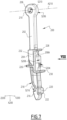
- a sheet of warp threads 1 comes from a beam 2.
- Each warp thread 1 passes through the eyelet 3a of a heddle 3 intended to open the pitch to allow the passage of a weft in order to constitute a fabric T which winds on a coil 4.
- Only two heddles 3 and 3' are represented on the figure 1 , the rail 3 being in the high position, while the rail 3' is in the low position.
- the lower end of each heddle is connected to the fixed frame of the loom M by a tension spring 5, while its upper end is secured to an arch 6.
- each arch has an end 6a secured to a housing 10 of the shed forming mechanism 7, this arch passing through a block 11 suspended from a cord 12 of which the two ends are respectively secured to two movable hooks 13 intended to be selectively lifted by knives 14 driven by a movement of alternating vertical oscillations in opposition to phase, as represented by the arrows F1 at the figure 1 .
- Other configurations of the arches, cords and mittens are possible.
- the shedding mechanism 7 can also be described as a “Jacquard module” and comprises a stack of several unit boxes, for example eight boxes.
- a selection device comprising an electromagnet and two retaining levers, is disposed in each unit housing.
- two hooks 13 are movable in each unitary housing longitudinally, that is to say along the longest dimension of the housing 10, which is vertical in the installed configuration of this housing within the shedding mechanism 7 mounted in the profession M.
- These two movable hooks are, preferably, integral with the same cord, such as the cord 12 shown in figure 1 from which is suspended the muffle 11 in which the arch 6 passes.
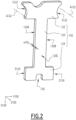
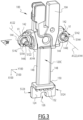
- Each electromagnet 100 of the shedding mechanism 7 comprises a ferromagnetic core 102, shown alone in the diagram. figure 2 , a carcass 104 made of non-magnetic material, a winding 106 wound around an intermediate part of the core 102, a covering 108 and electrical contacts 110 intended to be connected to two electrical cables not shown which connect it to the electronic control unit 8 and which allow the selective power supply of this electromagnet 100.
- the carcass 104 and the covering 108 together form a non-magnetic part of the electromagnet 100.
- the winding 106 and the electrical contacts 110 also belong to the non-magnetic part of the electromagnet 100.
- “amagnetic” is meant with a very low magnetic susceptibility, such that a non-magnetic part does not can interact magnetically with a ferromagnetic part.
- X100 as a longitudinal axis of the electromagnet 100 oriented from top to bottom at the figure 2 .
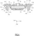
- Y100 as a transverse axis of the electromagnet 100 oriented from left to right at the Figure 4 .
- Z100 as an axis of thickness or depth of the electromagnet 100, that is to say also the axis of smallest dimension of the electromagnet 100.
- the axes X100, Y 100 and Z100 together form a mark orthogonal with direct orientation.
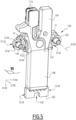
- THE figures 4 And 6 are sections taken respectively in the direction of axis X100 at the Figure 3 and in the direction opposite to the X100 axis at the Figure 5 .
- the core 102 has a thickness e102, measured parallel to the axis Z100, which is constant.
- the core 102 generally has an I shape, with a longitudinal and central branch 120, which extends in a direction parallel to the axis X100, and two transverse branches 122 and 124, which extend mainly in directions parallel to the Y100 axis.
- the longitudinal and central branch 120 is an intermediate part between the transverse branches 122 and 124.
- the lateral ends of the upper transverse branch 122 form two upper polar surfaces S122 of the electromagnet 100, these first polar surfaces being defined in the edge of the core 102, being concave and being in the form of a section of cylinder with circular section centered on a axis A122 perpendicular to the main flat surfaces of core 102. Axes A122 are parallel to axis Z100.
- the lateral ends of the lower transverse branch 124 form two lower polar surfaces S124 of the electromagnet 100. These second polar surfaces S124 are provided in the edge of the core 102, flat and parallel to the axes X100 and Z100.
- the first polar surfaces S122 are offset from the second polar surfaces S124 along the axis X100.
- a centering notch 126 is provided in the middle part of the lower branch 124, on an edge of this lower branch opposite the central branch 120.
- the centering notch is arranged between and at an equal distance from the lower polar surfaces S124, according to the Y100 axis.
- the carcass 104 is overmolded around the core 102 which it partially surrounds.
- overmolded we mean that the material of the carcass 104 is injected into a mold in which the core 102 has previously been placed, so that the material of the carcass 104 surrounds this core 102 and is fixed on this core after hardening.
- the carcass 104 is formed from a non-magnetic material, for example of the thermoplastic polymer type, optionally loaded with fibers.
- the carcass 104 is integral with the core 102 and has a fixed position relative to the core 102.
- the carcass surrounds the upper transverse branch 122 of the core 102 while being flush with the surfaces S122.
- the carcass 104 is extended, on either side of the upper transverse branch 122, by a sole 142 and by a guide shaft 144 centered on a respective axis A144.
- the two parts 142 and the two parts 144 are parts of the carcass 104 which are integral with the rest of the carcass 104, in particular with the part of this carcass which is arranged around the upper transverse branch 122.
- each guide shaft 144 is connected to the carcass 104 and in particular to the adjacent sole 142 in a non-removable manner.
- Axes A144 are parallel to axis Z100.
- Each axis A144 coincides with the central axis A122 of the adjacent upper polar surface S122. Thus each axis A144 is at the same longitudinal level as the adjacent upper polar surface S122.
- Each guide shaft 144 has a cylindrical external shape with a circular section and its external peripheral surface is denoted S144.
- the carcass 104 also defines a centering pin 146 which extends opposite a middle portion of the upper branch 122 and which is centered on an axis A146 parallel to the axes A144 and to the axis Z100.
- the centering pin 146 is also cylindrical with a circular section. Unlike the guide shafts 144, it is hollow, whereas the guide shafts are solid.
- the carcass 104 comprises two bands 148 which cover the edges 120A and 120B of the central branch 120, which are perpendicular to the axis Y100, but not the side faces 120C and 120D of this central branch, which are perpendicular to the axis Z100 .
- the carcass 104 also includes a foot 150, which covers the junction zone between the branches 120 and 124, and slats 152.
- the lower transverse branch 124 projects from the carcass 104 both in a longitudinal direction of the ferromagnetic core 102, parallel to the axis X100, and in a transverse direction of this core, parallel to the axis Y100.
- the carcass 104 does not extend at the level of the lower polar surfaces S124.
- a sole 142 is arranged in the vicinity of one end of each guide shaft 144 and extends in a ring around it, while connecting this shaft to the rest of the carcass 104.
- the soles 142 are formed on the non-magnetic part of the electromagnet 100.
- S142 a surface of each sole 142 which is annular, perpendicular to the axis Z100 and turned towards the guide shaft 144 that this sole surrounds.
- This surface S142 is perpendicular to the axis A144 of the adjacent guide shaft 144 and extends in a ring, that is to say over 360°, around this guide shaft.
- Surfaces S142 and S144 are adjacent and perpendicular.
- S'142 the peripheral surface of a sole 142. This surface is a portion of a cylinder with a circular base centered on the axis A144 of the adjacent guide shaft 144. Thus, the peripheral surface S'142 of a sole 142 is coaxial with the external peripheral surface S144 of the adjacent guide shaft 144.
- the surface S142 of a sole 142 delimits, with the external peripheral surface S144 of the adjacent guide shaft 144 and with the upper polar surface S122 which faces it, a volume V1 for receiving a part of a lever. retainer 200 represented alone in figures 7 to 9 . More precisely, the surface S144 defines the volume V1 radially to the axis A144 in a direction converging towards this axis. The surface S122 defines the volume V1 radially to the axis A144 in a direction diverging with respect to this axis. The surface S142 axially defines the volume V1, in a direction going from a free end 144E of the shaft 144 towards the adjacent sole 142, that is to say here in a direction opposite to that of the axis Z100.
- the volume V1 which is defined by the electromagnet 100, can be described as a partial reception housing for the retaining lever 200.
- each guide shaft 144 is constituted by a part of the electromagnet 100, in particular in a single piece with the carcass 104, makes it possible to reduce the positioning tolerances of this guide shaft with respect to the ferromagnetic core 102 , more precisely the positioning tolerances between surfaces S144 and S122. This contributes to the precision of the geometric definition of the volume V1 and to the precision of the guidance of the retaining lever 200 relative to the ferromagnetic core 102.
- the winding 106 is produced by winding a wire in the form of a turn around the central branch 120 of the ferromagnetic core 102 equipped with bands 148. This winding is produced after the overmolding of the carcass 104 on the ferromagnetic core 102 so that the winding 106 is in contact with the side faces 120C and 120D of the central branch 120 but separated from the edges 120A and 120B by the strips 148. Each end of the wire constituting the winding 106 is connected to one of the two electrical contacts 110. The carcass 104 then ensures the electrical insulation between the two electrical contacts 110, and the electrical insulation between the core 102 and the two electrical contacts 110, including at the level of their connection to the winding 106.
- the covering 108 is applied to the parts 102, 104 and 106 by low pressure overmolding and forms, in particular, a protective layer of the winding 106. geometry of the covering 108 is deduced from the comparison of the figures 3 And 5 . The covering 108, the winding 106 and the electrical contacts are then secured to the core 102.
- the lever 200 comprises an armature 202 made of a ferromagnetic material, for example pure iron, and a non-magnetic body 204 secured to the armature 202.
- the armature 202 interacts magnetically with the first and second polar surfaces S122, S124, as well as this emerges from the explanations which follow.
- the reinforcement 202 extends parallel to the axis with a circular section centered on an axis A210 parallel to the axis Z200.
- S210 the peripheral surface of the housing 210 which is an internal surface of the first end 206.
- S206 the external peripheral surface of the end 206.
- a portion S206A of this external peripheral surface S206 has a circular base centered on the axis A210. This portion S206A itself forms an external surface of the first longitudinal end 206.
- the second longitudinal end 208 of the frame 202 defines a second housing 212 which also passes through this frame from one side to the other, depending on its thickness and in which the non-magnetic body 204 is anchored by means of a bar 214, in one piece with the rest of the non-magnetic body 204 and which passes through the housing 212 right through.
- the non-magnetic body 204 is formed of a synthetic material, in particular a plastic material, for example of the thermoplastic polymer type, possibly loaded with fibers, which is overmolded on the metal frame 202 by filling the second housing 212, this which forms the bar 214.
- the non-magnetic body 204 has a fixed position relative to the armature 202 and is movable with the armature 202.
- the non-magnetic body 204 surrounds the end 208 of the armature 202 and extends it in the direction of the longitudinal axis X200, that is to say opposite the first longitudinal end 206.
- the non-magnetic body 204 forms a selection nose 216, a guide ramp 218 and a pin 220 surrounded, over its entire periphery, by a collar 222.
- the surface S216 of the selection nose faces towards the armature 202 and towards the first end 206 makes it possible to retain a movable hook 13 in or near its top dead center position, by engaging in an orifice of this movable hook.
- the nozzle 216 and the ramp 218 are located on the same side of this body, while the pin 220 and the collar 222 are located on the other side of this body.
- the surface portion S206A is located on the same side of the retaining lever 200 as the pin 220.
- the body 204 also includes a stop surface S204 intended to selectively come to bear against the electromagnet 100, depending on the position of the retaining lever.
- the selection nose 216, the guide ramp 218 and the pin 220 are formed in one piece with the abutment surface S204.
- the abutment surface S204 is adjacent to an external attraction surface S208 formed by the second end 208 of the armature 202, more particularly by a slice of a portion 208A of this second end which is not covered by the non-magnetic body 204.
- the abutment surface S204 is adjacent to the external attraction surface S208 to the extent that the abutment surface S204 and the external attraction surface S208 have a common boundary.
- the surfaces S206A and S208 are in electrical continuity since the armature 202 extends without discontinuity between these surfaces. This results, in particular, from the fact that, in this example, the frame 202 is in one piece.
- the portion 208A of the end 208 which defines the external surface of attraction S208 constitutes the portion of the frame 202 furthest from the first end 206.
- the armature 202 extends, in the direction of the axis X200, from the first end 206 to the junction of the external attraction surface S208 with the abutment surface S204. In other words, the armature 202 does not extend, over a significant length, inside the non-magnetic body 204, beyond the portion 208A.
- the abutment surface S204 is generally flat and parallel to the axes X200 and Z200. It is equipped with transverse grooves 224, parallel to the axis Z200, and which are juxtaposed in the longitudinal direction of the lever which is parallel to the axis X200. These grooves 224 have the effect that the surface S204 is not smooth but crenellated because it is formed from a juxtaposition of strips of material separated by the grooves 224.
- Deflectors are formed by the non-magnetic body 204 and are integral with the rest of this body.
- a first deflector 226 extends around the non-magnetic body 204, longitudinally at the same level as the abutment surface S204 but opposite this surface in the direction of the transverse axis Y200.
- Two other deflectors 228 and 230 are formed by the non-magnetic body 204 on the same side as the abutment surface S204 but at different levels along the longitudinal axis X200, on either side of this surface along this axis X200. More precisely, the deflector 228 is arranged, along the axis stop S204 and the pin 220.
- junction strips 232 connect the deflectors 228 and 230 in the longitudinal direction of the retaining lever 200. These junction strips 232 are arranged, along the axis Z200, on either side of the surfaces S204 and S208. The deflector 226 connects to the junction strips 232.
- the deflectors 226, 228 and 230 are continuous with each other.
- the deflectors 228 and 230 and the junction strips 232 form a continuous border around the surfaces S204 and S208 seen in the direction of arrow VIII at the Figure 7 .
- the deflector 226 is disposed on the same side of the non-magnetic body 204 as the selection nozzle 216, while the pair of deflectors 228 and 230 are disposed on the same side as the abutment surface S204 and the external attraction surface S208.
- the deflector 226 is arranged longitudinally, that is to say along the axis X200, between the deflectors 228 and 230.
- the shedding mechanism 7 also includes one or more unit housing(s) 300 which is or are part of the housing 10.
- the number of housings 300 which are part of the shedding mechanism 7 depends on the number of electromagnets 100. In practice, as many unit boxes 300 are provided as there are electromagnets 100.
- An orthogonal reference X300, Y300, Z300 is associated with each unitary housing 300. This reference is defined respectively by a longitudinal axis
- Each unitary housing 300 includes a half-shell 302 visible in its entirety in the upper part of the Figure 10 and which delimits a portion 304 for receiving a selection device 400 formed of an electromagnet 100 and two associated retaining levers 200, and a guide portion 306 of the two movable hooks 13 intended to be selected by means of the selection device. selection.
- the unitary housing 300 illustrated in the figures, with its electromagnet 100, comprising two pairs of first and second polar surfaces, and its two retaining levers 200 arranged on either side of the electromagnet along the axis Y100, is used in two-position Jacquard-type shedding mechanisms used for weaving so-called “flat” fabrics.
- the receiving portion 304 is shown on a larger scale in the lower right part of the Figure 10 , while a portion of a cover 308, corresponding to portion 304, is represented in the lower left part of the Figure 10 .
- the half-shell 302 and the cover 308 together constitute a unitary housing 300.
- the bottom 303 of the half-shell 302 which is parallel to the axes rods or screws for securing several boxes 300 belonging to a stack of unit boxes of the shedding mechanism 7 which together form all or part of the box 10.
- the unitary housing 300 defines a recess 314, which crosses the bottom 303 from side to side and which delimits a volume for partial reception of the electromagnet 100, and two zones 316 for receiving two associated retaining levers 200 to the electromagnet 100.
- the bottom 303 of the half-shell 302 is crossed, right through in the direction of the axis Z300, by a centering housing 320 of circular shape and intended to receive the centering pin 146 in the mounted configuration of the electromagnet 100 in the unitary housing 300.
- This centering housing has a geometry complementary to that of the centering pin 146.
- a centering pin 322 projects from the bottom 303, parallel to the axis Z300, and is arranged, along the axis X300, between the recess 314 and the guide portion 306. This centering pin 322 is arranged opposite the centering housing 320 relative to the recess 314. This centering pin is intended to be engaged in the centering notch 126 of the ferromagnetic core 102 in the mounted configuration of the electromagnet 100 in the unitary housing 300.
- the unitary housing 300 also forms baffles 324 in each zone 316 for receiving a retaining lever 200.
- the unitary housing 300 defines a housing 326 in the form of a portion of a cylinder with a circular section for receiving a sole 142 of the electromagnet 100.
- Each housing 326 is defined by an annular surface 328 and by a rib 330 which is of cylindrical internal shape with circular section and complementary to the external peripheral surface S'142 of a sole 142 of the electromagnet 100.
- the cover 308 the face visible to the Figure 10 is that which is normally turned towards the bottom 303 of the half-shell 302, defines orifices 332 for passing rods or fixing screws, these orifices 332 being aligned with the orifices 312 in mounted configuration of the cover 308 on the half-shell 302.
- This cover 308 also defines a centering housing 334 which is aligned with the centering housing 320 in the mounted configuration of the cover 308 on the half-shell 302. Alternatively, the cover 308 may not include a centering housing 334.
- This cover 308 further defines two hollow housings 336, each formed by an annular flat surface 338 and by a rib 339. These hollow housings 336 are respectively aligned with one housings 326 in the mounted configuration of the cover 308 on the half-shell 302.
- Elements 302 and 308 are made by injection of electrically insulating polymer material, optionally loaded with reinforcing fibers in order to improve their mechanical properties. Elements 302 and 308 are non-magnetic.
- the first longitudinal end 206 of the metal frame 202 is mounted around one of the guide shafts 144.
- the axes A144 and A210 are combined , the surfaces S144 and S210 face radially the axis A144 and the respective dimensions of the surfaces S144 and S210 are chosen to allow pivoting of each retaining lever 200 around the axis of oscillation X144 while effectively guiding this pivoting movement.
- the orthogonal marker X100, Y100, Z100 and each orthogonal marker axis A144 of the guide shaft around which the retaining lever 200 is mounted In the mounted configuration of a selection device 400, the orthogonal marker X100, Y100, Z100 and each orthogonal marker axis A144 of the guide shaft around which the retaining lever 200 is mounted.
- each retaining lever 200 extends generally in the longitudinal direction of the unitary housing 300, that is to say parallel to the axis X300, downwards at from the first end 206 of this retaining lever.
- the orthogonal marks X100, Y100, Z100, X200, Y200, Z200 and X300, Y300, Z300 are generally combined.
- each retaining lever 200 faces one of the lower polar surfaces S124 of the electromagnet 100 parallel to the axis Y100, without being in contact with this polar surface.
- Each retaining lever 200 is mobile, around the axis A144 of the guide shaft 144 around which the first longitudinal end 206 of its frame 202 is mounted, between a position pressed against the electromagnet, in the example pressed against the lower branch 124 of the ferromagnetic core 102, and a position remote from the electromagnet in which an empty space E of non-zero dimensions along the axes X100, Y100 and Z100 exists between the electromagnet, in the example the lower branch 124, and the lever 200.
- the thickness of the empty space E which is measured along the Y axis, is non-zero in the remote position of the retaining lever 200 relative to the electromagnet 100.
- the terms “remote” and “plated” used to define the positions of the retaining lever relative to the electromagnet concern the remote or flat nature of its surface of stop S204 with respect to the electromagnet.
- the retaining lever 200 shown in the lower part of the Figure 11 is in the pressed position against the electromagnet, while the lever 200 represented in the upper part of the Figure 11 is in a position away from the electromagnet.
- the surface S204 is in contact with a lower polar surface S124, to the point that it limits the pivoting movement of the lever 200 represented in the lower part to the Figure 11 , in the trigonometric direction around the axis A144 of the guide shaft 144 on which this lever 200 is pivotally mounted.
- the external attraction surface S208 is not in contact but at a distance from the lower polar surface S124, in the sense that there exists a transverse clearance J1 of non-zero dimension between the surfaces S208 and S124.
- the dimension of clearance J1 is measured parallel to axes Y100, Y200 and Y300.
- the presence of the clearance J1 of non-zero dimension over the entire length of the surface S208 along the axis X100 and over the entire thickness of the surface S208 taken along the axes Z100, Z200, Z300 means that an air gap exists between surfaces S124 and S208. This air gap exists between the armature 202 and the polar surface S124.
- the abutment surface S204 protrudes transversely, in a direction parallel to the axis Y200 and turned towards the electromagnet in the mounted configuration of the retaining lever 200, relative to the external attraction surface S208, and this abutment surface S204 comes into contact with the second polar surface S124 by maintaining the external attraction surface S208 at a distance from the second polar S124 when the lever 200 pivots from its position away from the electromagnet to its position pressed against the electro magnet.
- the surface S208 is an external attraction surface to the extent that, when the lever 200 is in its position pressed against the electromagnet 100 and when this electromagnet is activated, the magnetic attraction force between the ferromagnetic core 102 and the The metal frame 202 is exerted through this surface S208.
- the reinforcement 202 in particular the portion 208A of the end 208, does not extend longitudinally at the level of the entire abutment surface S204.
- the external attraction surface S208 is arranged longitudinally relative to the retaining lever 200, that is to say along the axis X200, between the abutment surface S204 and the axis A210.
- the length l8 of the external attraction surface S208 is greater than the length l4 of the abutment surface S204 which comes opposite the lower polar surface S124 in the pressed position of the retaining lever 200 and which forms the contact zone between the surfaces S204 and S124.
- Lengths l4 and l8 are measured parallel to the X200 axis. In the embodiment shown in figures 1 to 15 , the entire abutment surface S204 faces the lower polar surface S124 in the pressed position of the retaining lever 200.
- this surface S204 comes into contact with the lower polar surface S124 or either facing the lower polar surface S124.
- l48 the length, measured parallel to the axis the surfaces S208 and S204 in a plane parallel to the plane of the figure 8 .
- This line L1 is perpendicular to the plane of the Figure 12 and makes visible, on the face of the retaining lever 200 shown in figure 8 , the junction zone Z1 between the parts 202 and 204.
- the length -e48 therefore corresponds to the length of coverage of the second longitudinal end 208 by the abutment surface S204.
- the ratio l48/l4 is less than 0.2.
- the abutment surface S204 covers the armature 202 for less than a fifth of the length l4 of the useful part of the abutment surface S204, which serves to support it against the electromagnet.
- the deflectors 226, 228 and 230 are engaged in reception zones Z226, Z228 and Z230 formed by the baffles 324.
- the cooperation of the deflectors and the baffles allows to isolate certain internal parts of the unitary housing 300 equipped with the selection device 400 from the guide portion 306, which makes it possible to protect these parts against the accumulation of dust, fluff or grease.
- a helical compression spring 340 is interposed between a central rib 342 of the housing 300 and the non-magnetic body 204 of a retaining lever 200.
- Each spring 340 has the function to recall by default the retaining lever 200 against which it is supported towards its position distant from the electromagnet 100.
- the pin 220 is engaged inside the spring 340 and makes it possible to center this spring , while the collar 222 makes it possible to accommodate the terminal turn of the spring all around the support pin 220.
- the terminal turn of the spring 340 necessarily rests on this collar 222 without risk that this terminal turn slides on the side of the pin 220, which guarantees the repeatability of the return force of the spring 340.
- Each movable hook 13 comprises a body 502 made of plastic material and a flexible strip 504 mounted on the body 502.
- the flexible strip which is preferably metallic, is intended to come into sliding support against the guide ramp 218 of a lever.
- retainer 200 and has an orifice 508, visible in dotted lines at the Figure 11 and known per se, in which the selection nozzle 216 of the retaining lever 200 in question can be engaged.
- each body 502 is overmolded on one end of the cord 12 which supports the muffle 11.
- Each body 502 defines a support nozzle 506 on a knife 14. To do this, each support nozzle 506 projects laterally from the unitary housing 300 in which the movable hook 13 is installed to come to rest, by cooperation of shapes, on the upper face of the knife.
- the first longitudinal end 206 is received partially in the volume V1.
- the surface portion S206A is arranged facing the first polar surface S122 formed by the ferromagnetic core 102, these facing surfaces being in the form of a cylinder portion with a circular base centered on the axes A122, A144 and A210 then combined. These surfaces delimit between them a clearance J2, radial to the axes A122, A144 and A210.
- This radial clearance J2 has a non-zero thickness, this thickness being measured radially at the axes A122, A144 and A210.
- This radial clearance J2 defines an air gap between the surfaces S122 and S206A.
- the radial thickness of the air gap defined by the clearance J2 can be between 0.1 and 0.2 millimeters (mm), preferably of the order of 0.15 mm.
- P144 a transverse plane parallel to the axes Y100, Y200 and Y300, on the one hand, Z100, Z200, Z300, on the other hand and perpendicular to the axes X100, X200 and X300, and containing the axes A122, A144 and A210.
- the air gap defined by the radial clearance J2 extends around the axis A122 over a global angular sector with apex angle ⁇ .
- a first part of this overall angular sector is located below the transverse plane P144, on the side of the second polar surface S124 relative to this plane, and has a vertex angle ⁇ 1.
- a second part of this overall angular sector is located above the transverse plane P144, that is to say opposite the second polar surface S124, and has a vertex angle ⁇ 2.
- the sum of angles ⁇ 1 and ⁇ 2 is equal to angle ⁇ .
- the angles ⁇ , ⁇ 1 and ⁇ 2 respectively represent the angular amplitudes of the overall angular sector and its first and second parts.
- each first polar surface S122 of the electromagnet 100 extends on either side of the transverse plane P144 and comprises a first portion S122A located, relative to this plane, on the same side as the second surface polar S124 and which has an angular amplitude ⁇ 1, as well as a second portion S122B located, relative to this plane, opposite the second polar surface S124 and which has an angular amplitude ⁇ 2.
- the ⁇ 1/ ⁇ ratio is between 0.2 and 0.4, preferably equal to 0.33. In this preferred case, the ⁇ 1/ ⁇ 2 ratio is 0.5.
- the good geometric precision obtained at the level of the air gap defined between the surfaces S122 and S206A makes it possible to optimize the size of these surfaces.
- the ratio between the diameter of the surface S122 and the diameter of the surface S144 can be chosen greater than 1.4, preferably of the order of 1.5.
- This good precision also makes it possible to separate, in the longitudinal direction parallel to the axis X100 or to the axis X300, the first and second polar surfaces S122 and S124, without penalizing the longitudinal size of the electromagnet.
- the carcass 104 is overmolded onto the ferromagnetic core 102, then the winding 106 is fitted, the contacts 110 and the connecting wires are fitted. between these contacts and the winding 106 and then to the overmolding of the covering 108.
- the electromagnet 100 thus manufactured, with its guide shafts 144, is attached and immobilized in the half-shell 302 of the unitary housing 300.
- the introduction of the electromagnet 100 into the recess 314 takes place in a direction parallel to the axis Z300, by inserting the centering pin 146 into the centering housing 320 of the unitary housing 300.
- the centering pin 146 which is arranged between the two upper polar surfaces S122 and at an equal distance from them, allows, by its fitting into the bottom 303 of the half-shell 302 of the unitary housing 300, to ensure the positioning of the electromagnet 100 in the unitary housing 300, both in the longitudinal and transverse directions respectively parallel to the axis X300 and to the axis Y300.
- centering notch 126 of the ferromagnetic core 102 is placed, without play in the lateral direction parallel to the axis Y300, around the centering pin 322 of complementary shape provided on the half-shell 302.
- the winding 106 of the electromagnet 100 is then aligned with the recess 314 made through the bottom of the housing parallel to the axis Z100.
- the carcass 104 of the electromagnet 100 then rests by flat support on two bearing surfaces of the bottom 303 of the half-shell 302, one disposed between the lower polar surfaces S124, the other disposed between the upper polar surfaces S122 .
- the external peripheral surface S'142 of the sole 142 is an external radial surface in the portion of a cylinder centered on the shaft 144 which then coincides with the axis A122.
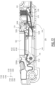
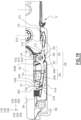
- each sole 142 of the electromagnet 100 is engaged in a housing 326 of the unit housing 300, as shown in figures 14 And 15 .
- the external radial surface S'142 of a sole 142 then faces the corresponding rib 330 in the plane of the Figure 15 , in a longitudinal direction parallel to the axes X100, X200 and X300 which is vertical and directed downwards. A part of the rib 330 is therefore arranged facing the surface S'142 in the longitudinal direction.
- a reduced longitudinal clearance J3 is defined between the external peripheral surface S'142 and the rib 330 in the plane of the Figure 15 .
- This game J3 is therefore vertical and has, in practice, a non-zero thickness when the electromagnet 100 is placed in the unit housing 300 in order to prevent this installation from generating a hyperstatic situation.
- the thickness of the game J3 is measured parallel to the axis X300.
- the thickness of the J3 game is less than or equal to 0.5 mm.
- the oscillation axes A144 are fixed relative to the half-shell 302 and the electromagnet 100.
- the free ends 144E of the guide shafts 144 extend opposite the bottom 303 of the half-shell 302.
- the two guide shafts 144 extend with their axes A144 parallel to the axis Z300 and are perpendicular to the bottom 303 of this half shell.
- the retaining levers 200 are then placed around the guide shafts 144 of the carcass 104, providing that a first longitudinal end 206 of each retaining lever 200 comes to surround a guide shaft 144.
- the axis A210 of each retaining lever 200 is aligned with the axes A122 and A144, then the first longitudinal end 206 of the armature 202 is partially engaged in the volume V1, by an axial translation parallel to the axes A122, A144 and A210, up to to come into abutment against the surface S142 of one of the soles 142. This amounts to hooking the retaining levers on the electromagnet in place in the unit housing.
- each external attraction surface S208 faces a lower polar surface S124 of the electromagnet 100, in the transverse direction parallel to the axes Y100, Y200 and Y300.
- each retaining lever 200 is neither facing the first polar surface S122, nor facing the second polar surface S124 but arranged longitudinally at the central branch 120 of the core 102 and the winding 106.
- the deflectors 226, 228 and 230 of the non-magnetic body 204 are engaged in the zones Z226, Z228 and Z230 defined by the baffles 324, at course of the axial translation mentioned above.
- these retaining levers are connected to the rest of the selection device 400 and each movable in rotation around an axis A144 which is fixed relative to the unitary housing 300 since the electromagnet 100 is immobilized in the unit housing 300.
- the external radial surfaces S144 of the guide shafts 144 therefore form cylindrical guide surfaces which cooperate, with reduced clearance, with the retaining levers 200, more particularly with the surfaces S210 of the housings 210, in their pivoting movement around their axis oscillation A144.
- reduced clearance we mean a radial clearance at the oscillation axis A144 strictly less than the clearance J2, to guarantee a non-zero air gap between the surface S206 and the first adjacent polar surface S122, and therefore the absence of contact between the armature 202 of the lever 200 and the polar surface S122, between the remote position and the pressed position of the retaining lever.
- the guide surfaces S144 are formed on the non-magnetic part of the electromagnet. Each tree of guide 144 forms a point of attachment of a lever 200 to the housing 300, this point of attachment being fixed relative to the electromagnet 100.
- the cooperation of the deflectors 228 and 230 with the zones Z228 and Z230 defined by the baffles 324 also makes it possible to isolate a zone of attraction defined between, on the one hand, the lower polar surface S124 and, on the other hand, the external surface attraction S208 and the abutment surface S204. This makes it possible to keep this attraction zone free of grease and dust to guarantee a satisfactory air gap between the lower polar surface S124 and the external attraction surface S208 when the retaining lever 200 is in its position pressed against the electromagnet.
- the two retaining levers 200 can then oscillate around their respective guide shafts 144, between the remote and placed positions respectively represented in the upper part and in the lower part of the Figure 11 . In a manner known per se, this makes it possible to selectively retain the movable hooks 13 in position, depending on a command sent to the electromagnet 100 by the electrical contacts 110.
- the movable hooks 13 and the cords 12 can then be placed in the guide portion 306 of the half-shell 302. Alternatively, the movable hooks 13 and the cords 12 are placed in the half-shell before the elements 100 and 200.
- the free ends 144E of the guide shafts 144 protrude from the retaining levers 200, in a direction parallel to the axes Z100 , Z200 and Z300. It is then possible to cover the half-shell 302 with the cover 308, the half-shell 302 and the cover 308 being stacked along the axis Z300, by aligning the orifices 332 with the orifices 312 and the housings 336 with the free ends. 144E of the guide shafts 144. Securing rods or screws are then placed in the orifices 312 and 332.
- half-shells 302 each equipped with a selection device 400, the bottom 303 of a half-shell serving as a cover for the adjacent half-shell, and to use a cover 308 only for the last half-shell 302.
- This configuration is partially represented in figures 14 And 15 .
- the orifices 312 of the half-shells 302 are superimposed and securing rods or screws are then placed in these orifices.
- first unitary housing is formed by the first half-shell and by the bottom 303 of the second half-shell. The same applies to the other unitary cases, except for the last one which is covered by the cover 308.
- the recessed housing 344 is provided on the side of the bottom 303 of the second half-shell 302 opposite the electromagnet 100. contained in this half-shell.
- the bottom 346 of the recessed housing 344 of the second half-shell bears against the free end 144E of the guide shaft 144, in a direction parallel to the axis Z300.
- the cylindrical wall 348 which defines the housing 344 is substantially complementary to the external peripheral surface S144 of the guide shaft 144, which makes it possible to center each guide shaft in the second half-shell 302 of the second unitary housing 300 .
- THE figures 14 And 15 show that the bottom of the first half-shell of the stack of unitary boxes is not equipped with a recessed housing 344, which would be useless.
- the flat and annular surface 338 constituted by the bottom 303 of the second half-shell 302 and which surrounds the recessed housing 344 faces the sole 142 of the electromagnet received in the first half-shell.
- the first end 206 of the frame 202 is arranged between the surfaces S142 and 338 which face each other in a direction parallel to the axis Z300.
- the surface 338 serves as a cover for the volume V1 in which the frame 202 is partially received.
- cover 308 is the flat and annular surface 338 of a recessed housing 336 which closes the volume V1.
- the housings 300 are centered relative to each other in the longitudinal and transverse directions parallel to the axes X300 and Y300 and are supported against each other in the direction of the axis Z300.
- each electromagnet 100 selectively controls, by means of the two retaining levers 200 associated with it, the retention or release of one and the other of the two movable hooks 13 which are arranged on either side of this electromagnet in the same unit box 300.
- the two movable hooks 13 are shown near the dead center of their trajectory.
- the mobile hook 13 visible in the upper part of the Figure 11 is hooked on the corresponding retaining lever 200, by introducing the selection nozzle 216 of this retaining lever into an orifice 508 of the strip 504 of this movable hook, which is possible because this retaining lever 200 is in a position far from the electromagnet 100.
- the movable hook 13 shown in the lower part of the Figure 11 is released from the selection nose 216 of the corresponding retaining lever, which is held in the pressed position, to the point that its selection nose 216 is not found on the trajectory of the upper end of the strip 504 of this movable hook.
- the strip 504 of each movable hook 13 comes into contact with the guide ramp 218 of the corresponding retaining lever 200 and exerts on this lever a lateral force directed towards the electromagnet parallel to the axis Y100, against the force exerted by the spring 340 engaged around the pin 220 of this retaining lever.
- This lateral force causes the retaining lever to pivot around its axis of oscillation A144 from its remote position shown in the upper part of the Figure 11 , in its plated position, shown in the lower part of this figure. This operation constitutes the leveling of the retaining levers 200.
- each retaining lever 200 between its position away from the electromagnet 100 and its position pressed against this electromagnet, the upper air gap, defined by the radial clearance J2, remains identical, with a non-zero value.
- the lower air gap defined between the external surface of attraction S208 and the lower polar surface S124 decreases until it presents a non-zero thickness represented by the clearance J1 at the Figure 12 .
- the non-zero value of the lower air gap is well controlled by the fact that the surfaces S204 and S208 are both carried by the retaining lever 200 and by the contacting of the abutment surface S204 against the electromagnet, in particular at the level of its lower polar surface S124 opposite which the external surface of attraction S208 is arranged.
- the value of the clearance J1 is chosen according to the magnetic force to be exerted on the retaining lever 200 to keep it in the pressed position against the electromagnet 100, which depends, among other things, on the magnetic properties of the armature 202 and the spring stiffness constant 340.
- the value of the clearance J1 is between 0.01 and 0.06 mm, preferably between 0.025 and 0.05 mm, more preferably of the order of 0.04 mm.
- each retaining lever 200 is configured to interact with the polar surfaces S122 and S124 of the electromagnet 100, depending on the activation of this electromagnet, in order to control the angular position of this retention lever. retained relative to the electromagnet, around its axis of oscillation A144. This makes it possible to select, that is to say maintain in the high position, or to release, that is to say let it go back down, a movable hook 13 resting on a knife 14, at the start of its downward movement .
- the electromagnet 100 makes it possible to control whether or not the retaining lever 200 is held in the position pressed against the electromagnet.
- a movable hook 13 has been retained by the retaining lever 200, when the corresponding knife 14 again reaches the vicinity of the top dead center position of its trajectory, the knife 14 again pushes back the body 502 and the blade 504 of the movable hook upwards, the strip again comes to rest against the guide ramp 218 to press the retaining lever against the lower polar surface S124 of the electromagnet 100, as part of the leveling.
- the movable hook 13 can be kept pressed against the electromagnet or not, depending on the activation of the electromagnet 100.
- the movable hook ensures the movement of the retaining lever from its remote position towards its pressed position, without pressing the retaining lever against the electromagnet, the remaining travel of the retaining lever to reach its pressed position being caused by the activation of the electromagnet (“call”).
- a single abutment surface S204 is used which is as far away as possible from the oscillation axis A144 of the retaining lever 200, which makes it possible to reduce the length of the metal frame 202 to the minimum length necessary to establish the magnetic circuit between the first and second polar surfaces.
- the metal reinforcement may only extend as far as the junction between the abutment surface S204 and the external attraction surface S208, which is marked by the line L1. This makes it possible to reduce the length of the armature 202, therefore the inertia of the retaining lever 200 and its cost price.
- the retaining lever 200 carries a stop surface S204 which is arranged along the axis X200 between two portions S208A and S208B of the external attraction surface S208.
- the external attraction surface S208 is distributed, in the longitudinal direction parallel to the axis X200, on either side of the abutment surface S204.
- a non-zero air gap J1 is present between each of the two portions S208A, S208B and the adjacent lower polar surface S124 in the pressed position of the lever 200.
- the external surface of attraction S208 is at a distance of the second polar surface S124.
- the abutment surface S204 is arranged, in a longitudinal direction parallel to the axis X200, between the axis A210 and the external attraction surface S208.
- the abutment surface S204 is arranged, within the shedding mechanism 7 in mounted configuration, above the external attraction surface S208, while it is arranged below in the method of carrying out the figures 1 to 15 .
- the first polar surfaces S122 formed by the ferromagnetic core 102 of the electromagnet 100 are arranged at the level of the lower transverse branches 122 of the core 102 located in the lower part of the electromagnet 100, while the second polar surfaces S124 are arranged at the level upper transverse branches 124 of the core 102 located in the intermediate part of this electromagnet 100.
- the second polar surfaces S124 are arranged above the first polar surfaces S122, in a longitudinal direction of this electromagnet 100 which is parallel to the axis X100.
- the carcass 104 of the electromagnet 100 is pierced with two positioning housings 145 intended to receive positioning members provided in the body 300 of the shedding mechanism.
- the second polar surfaces S124 are crenellated and provided with transverse grooves 125, which extend parallel to the axis Z100 and which delimit between them separate strips of material, in a manner comparable to the grooves 224 and strips formed on the surface S204 of the first embodiment.
- two abutment surfaces S204 are delimited on the retaining lever 200 on either side, in a longitudinal direction parallel to the axis X200, of the external attraction surface S208 defined by the armature 202 of this lever .
- the portion 206 of the frame 200 an opening 210 of which is engaged around the guide shaft 144, is defined in an intermediate zone of the lever 200.
- the frame 202 comprises, in addition this part 206, two branches 205 and 207 which extend in opposite longitudinal directions, generally parallel to the axis X200, from this portion 206 and which respectively carry a first portion 204A and a second portion 204B of the non-magnetic body 204 of this retaining lever 200.
- the first portion 204A defines the selection nozzle 216 and the guide ramp 218.
- the second portion 204B defines the two abutment surfaces S204.
- a spring 340 tends to move the abutment surfaces S204 away from the electromagnet 100 by default.
- the selection nozzle and the retaining ramp are formed directly on the frame 202 and can cooperate with a hook molded from synthetic material, as envisaged in EP-A-0823501 .
- each guide shaft 144 is arranged on the unitary housing 300 with which it is in one piece, projecting from the bottom 303 of the half-shell 302 for receiving the electromagnet 100, as envisaged in EP-A-1413657 Or EP-A-0823501 Or EP-A-0577524 . There is no sole 142. After mounting the electromagnet 100 in the half-shell 302 and in the operating configuration of the mechanism 7, the axes of oscillation A144 are fixed relative to the half-shell 302 and to the electromagnet 100.
- the portion 206 of the armature 202 which is articulated on the guide shaft is an intermediate portion of this armature 206 and the armature 202 comprises two branches 205 and 207 which extend respectively from this part 206, in two opposite directions in the longitudinal direction. This is common with the previous embodiment.
- the non-magnetic body 204 defines, on the side of the branch 205, a guide ramp 218 and a through orifice 216 delimited, on the longitudinal side of the ramp 218, by a surface S216 for hooking the nose 506 of the movable hook 513.
- This non-magnetic body 204 defines, opposite the ramp 218 relative to the portion 206, a stop surface S204 which adjoins an external surface of attraction S208 defined by the end 208 of the branch 207 and which comes opposite of the second polar surface S124.
- the guide ramp 218 and the selection surface S216 are here in one piece with the abutment surface S204.
- the fact that the axis of oscillation of the retaining lever is provided at the longitudinal level of the first polar surface guarantees good control of the air gap between the armature of the movable retaining lever and this first surface.
- polar with a radial thickness equal to the non-zero clearance J2, taken radially at the axes A122, A144, whatever the position of the retaining lever between its remote position and its position pressed against the electromagnet.
- the clearance J2 can be variable over the angular extent of the air gap between the armature and the first polar surface.
- the stop surface guarantees good control of the air gap of thickness equal to the clearance J1, measured parallel to the axes Y100, Y200 and Y300, between the retaining lever and the second polar surface, when the lever retained is in its position pressed against the electromagnet.
- the stop surface is placed on the retaining lever, rather than on the electromagnet, its position with respect to the guide ramp and the selection nose is defined with good precision, in particular better precision than if this surface was provided on the electromagnet.
- providing the abutment surface on the lever retainer simplifies the construction of the electromagnet, which constitutes a more bulky and more complicated part to manufacture than the retainer lever itself.
- the abutment surface S204 is in one piece with the guide ramp 218, as in the first, second, third and fifth embodiments, this makes it possible to best adjust the stroke and the force that the hook must exert. movable 13 against the retaining lever to ensure leveling.
- the oscillating nature of the retaining lever 200 makes it possible to more effectively control the air gap between the external attraction surface S208 and the lower polar surface S124 than in the case of a retaining element comprising a flexible blade deformed during the leveling.
- abutment surface or the second polar surface is crenellated makes it possible to prevent clumps of grease from forming at these surfaces, which guarantees the air gap between the external surface of attraction and the second polar surface.
- the length of the portion of the second polar surface which cooperates with the abutment surface can be reduced by choosing for the external surface of attraction a length greater, preferably twice greater, than the length over which the surface of stop abuts against the lower polar surface, in the pressed position of the lever.
- the guide ramp is arranged longitudinally opposite the point of attachment of the retaining lever, formed by its first longitudinal end, with respect to the abutment surface and with respect to to the external surface of attraction, it is guaranteed that once the retaining lever is pressed against the electromagnet, the portion of the retaining lever which includes the external surface of attraction will not be deformed by a force exerted by the hook movable at the level of the guide ramp.
- the abutment surface of the retaining lever is in contact with the ferromagnetic core of the electromagnet.
- the presence of the recess 314 and the fact that the winding 106 is in direct contact with the side faces 120C and 120D of the branch central 120 of the ferromagnetic core 102 gives good compactness to each unit housing 300 equipped with an electromagnet 100, in a direction parallel to the axis Z300.
- the offset of the deflectors on each lateral side of the unitary housing causes them to form, on each transverse side of the retaining lever, a relatively long edge, which improves the seal obtained.
- the first polar surfaces S122 are offset relative to the second polar surfaces S124, in the longitudinal direction of the shedding forming mechanism. crowd which is parallel to the axes X100 and X300 which are then merged.
- the winding extends between the first pole surfaces S122 and the second pole surfaces S124 in the longitudinal direction.
- the abutment surface(s) S204 may or may not be projecting from the external attraction surface S208 in the direction of the electromagnet, but aligned with the external attraction surface or offset with respect to the external attraction surface in the other direction along the axis Y200 , opposite the electromagnet, while guaranteeing a non-zero air gap between the external attraction surface and the second polar surface in the pressed position of the retaining lever and guaranteeing contact between the electromagnet and the surface(s). stop in the pressed position of the retaining lever.
- the abutment surface(s) S204 may be adjacent to the external attraction surface(s) S208 in a transverse direction, parallel to the axis Y200, and not in a longitudinal direction, parallel to the axis X200 as in the examples in the figures.
- the retaining lever 200 can have generally the shape of that described with the reference 15 in EP-A-0851048 , with an abutment surface adjacent to the external attraction surface intended to interact with the upper polar surface and/or the lower polar surface of the upper electromagnet.
- the hitch connecting the cords 12 to the heddle 3 can be modified to allow three or four positions of the heddle to be reached, which makes it possible to weave fabrics other than so-called “flat” fabrics.
- the selection device then comprises more than two movable hooks, these movable hooks being secured, in pairs, to the same cord.
- a single movable hook 13 or more than two movable hooks can be provided in the housing 30.
Landscapes
- Engineering & Computer Science (AREA)
- Textile Engineering (AREA)
- Electromagnets (AREA)
- Looms (AREA)
Claims (15)
- Fachbildungsmechanismus (7) auf einer Webmaschine (M) vom Typ Jacquard, wobei dieser Mechanismus mindestens einen beweglichen Haken (13) umfasst, der durch ein Messer (14) in einer Längsrichtung (X100, X200, X300) zwischen einer unteren Totpunktposition und einer oberen Totpunktposition verschoben wird, in oder in der Nähe der der Haken durch eine Auswahlvorrichtung (400) zurückgehalten werden kann, die mindestens Folgendes umfasst:- einen Elektromagnet (100), der einen ferromagnetischen Kern (102) beinhaltet, der mindestens eine erste polare Fläche (S122) und mindestens eine zweite polare Fläche (124) definiert, wobei diese polaren Flächen voneinander gemäß der Längsrichtung versetzt sind;- einen Rückhaltehebel (200), der konfiguriert ist, um den beweglichen Haken zurückzuhalten, wenn dieser in oder in der Nähe seiner oberen Totpunktposition ist, wobei der Rückhaltehebel mit der Möglichkeit des Schwenkens zwischen einer vom Elektromagneten entfernten Position und einer gegen den Elektromagneten gedrückten Position um eine Schwingachse (A144) montiert ist, die mit Bezug auf den Elektromagneten (100) in der Betriebskonfiguration des Mechanismus befestigt ist, wobei der Rückhaltehebel Folgendes umfasst:-- einen ferromagnetischen Anker (202), der magnetisch mit der ersten und der zweiten polaren Fläche (S122, S124) in Wechselwirkung steht, um die Winkelposition des Rückhaltehebels um die Schwingachse zu steuern, wobei dieser Anker eine äußere Anziehungsfläche (S208) umfasst, die der zweiten polaren Fläche (S124) gegenüber liegt, wenn sich der Rückhaltehebel in der gegen den Elektromagneten gedrückten Position befindet,-- einen nichtmagnetischen Körper (204), der einstückig mit dem Anker ist, dadurch gekennzeichnet, dass der nichtmagnetische Körper (204) des Rückhaltehebels (200) mindestens eine Anschlagfläche (S204) umfasst, die- benachbart der äußeren Anziehungsfläche (S208) ist,- entfernt vom Elektromagneten ist, wenn sich der Rückhaltehebel in seiner vom Elektromagneten entfernten Position befindet; und- in Kontakt mit dem Elektromagneten ist, wenn sich der Rückhaltehebel in seiner gegen den Elektromagneten gedrückten Position befindet,und dadurch, dass in der gegen den Elektromagneten gedrückten Position des Rückhaltehebels die äußere Anziehungsfläche (S208) entfernt von der zweiten polaren Fläche (S124) ist.
- Mechanismus nach Anspruch 1, dadurch gekennzeichnet, dass jede Anschlagfläche (S204) in Richtung des Elektromagneten (100) mit Bezug auf die äußere Anziehungsfläche (S208) vorspringend ist.
- Mechanismus nach einem der vorhergehenden Ansprüche, dadurch gekennzeichnet, dass jede Anschlagfläche (S204) gemäß der Längsrichtung (X100, X200, X300) gegenüber der Schwingachse (A144) mit Bezug auf die äußere Anziehungsfläche (S208) angeordnet ist.
- Mechanismus nach Anspruch 3, dadurch gekennzeichnet, dass sich der Anker (202) gemäß der Längsrichtung (X100, X200, X300) und ausgehend von der Schwingachse (A144) nur bis zu einer Verbindungszone (L1) zwischen der äußeren Anziehungsfläche (S208) und der Anschlagfläche (S204) erstreckt.
- Mechanismus nach einem der vorhergehenden Ansprüche, dadurch gekennzeichnet, dass der nichtmagnetische Körper (204) des Rückhaltehebels (200) in einem Stück gefertigt ist und eine Auswahlfläche (S216) umfasst, die ausgelegt ist, um den beweglichen Haken (13) in oder in der Nähe seiner oberen Totpunktposition zurückzuhalten, und/oder eine Rampe (218) zur Wechselwirkung mit dem beweglichen Haken (13), um den Rückhaltehebel (200) aus seiner vom Elektromagneten (100) entfernten Position in seine gegen den Elektromagneten gedrückte Position zu verschieben.
- Mechanismus nach einem der vorhergehenden Ansprüche, dadurch gekennzeichnet, dass, wenn sich der Rückhaltehebel (200) in seiner gegen den Elektromagneten (100) gedrückten Position befindet, sich die Anschlagfläche (S204) in Auflage gegen die zweite polare Fläche (S124) befindet, und dadurch, dass die zweite polare Fläche eine äußere Fläche des ferromagnetischen Kerns (102) des Elektromagneten ist, die in Richtung des Rückhaltehebels (200) mit Bezug auf die nichtmagnetische Hülle (104) des Elektromagneten vorsteht.
- Mechanismus nach Anspruch 6, dadurch gekennzeichnet, dass eine Länge (ℓ8) der äußeren Anziehungsfläche (S208), gemessen gemäß einer Richtung parallel zur Längsrichtung (X100, X200, X300), grösser als eine Länge (-e4) der Anschlagfläche (S204) ist, die sich gegenüber der zweiten polaren Fläche (S124) befindet, wenn sich der Rückhaltehebel in seiner gegen den Elektromagneten (100) gedrückten Position befindet, wobei die Länge der Anschlagfläche parallel zur Länge der Anziehungsfläche gemessen wird.
- Mechanismus nach einem der vorhergehenden Ansprüche, dadurch gekennzeichnet, dass, wenn sich der Rückhaltehebel (200) in seiner gegen den Elektromagneten (100) gedrückten Position befindet, der Rückhaltehebel (200) den beweglichen Haken (13) nicht in oder in der Nähe seiner oberen Totpunktposition zurückhält.
- Mechanismus nach einem der vorhergehenden Ansprüche, dadurch gekennzeichnet, dass der Elektromagnet (100) auf eine Gehäuse (300) des Mechanismus aufgesetzt und immobilisiert ist, dadurch, dass ein nichtmagnetischer Teil des Elektromagneten, der einstückig mit dem ferromagnetischen Kern ist, eine Fläche (S144) zur Führung des Schwenkens des Rückhaltehebels (200) um die Schwingachse (A144) umfasst, wobei diese Fläche zur Führung mit dem Rückhaltehebel (200) in einer radialen Richtung zur Schwingachse (A144) zwischen der entfernten Position und der gedrückten Position des Rückhaltehebels zusammenarbeitet, und dadurch, dass die Fläche zur Führung zylindrisch mit runder Basis, zentriert auf der Schwingachse, ist.
- Mechanismus nach einem der vorhergehenden Ansprüche, dadurch gekennzeichnet, dass der nichtmagnetische Körper (204) des Rückhaltehebels (200) einen Stift (220) und einen Flansch (222) umfasst, der den Stift auf seinem ganzen Umfang umgibt, und der konfiguriert ist, um eine spiralförmige Rückstellfeder (340) des Rückhaltehebels (200) hin zu seiner vom Elektromagneten entfernten Position in Auflage aufzunehmen.
- Mechanismus nach einem der vorhergehenden Ansprüche, dadurch gekennzeichnet, dass die Schwingachse (A144) auf der gleichen Ebene gemäß der Längsrichtung (X100, X200, X300) wie die erste polare Fläche (S122) angeordnet ist.
- Mechanismus nach einem der vorhergehenden Ansprüche, dadurch gekennzeichnet, dass der Anker (202) des Rückhaltehebels mit einer Lagerung (210) zur Aufnahme einer Welle (144) zur Führung der Schwenkens des Rückhaltehebels (200) zwischen seiner vom Elektromagneten (100) entfernten Position und seiner gegen den Elektromagneten gedrückten Position durchbrochen ist, und dadurch, dass sich diese Führungswelle gemäß der Schwingachse (A144) erstreckt, und dadurch, dass der Anker eine externe Fläche (S206A) umfasst, die der ersten polaren Fläche (S122) gegenüber liegt, mit einem Spiel (J2) von nicht null zwischen der entfernten Position und der gegen den Elektromagneten gedrückten Position des Rückhaltehebels.
- Mechanismus nach Anspruch 12, dadurch gekennzeichnet, dass er ein Gehäuse (300) umfasst, in dem der oder die beweglichen Haken (13) verschoben werden, und in dem der Elektromagnet (100) aufgesetzt und immobilisiert ist, und dadurch, dass die Welle (144) zur Führung des Schwenkens des Rückhaltehebels (200) auf dem Gehäuse oder auf einer nichtmagnetischen Hülle (104) des Elektromagneten gebildet ist.
- Mechanismus nach einem der vorhergehenden Ansprüche, dadurch gekennzeichnet, dass der ferromagnetische Kern (102) des Elektromagneten (100) einen Zwischenteil (120) umfasst, um den eine Wicklung (106) gebildet ist, und dadurch, dass die erste und zweite polare Fläche (S122, S124) auf beiden Seiten des Zwischenteils gemäß der Längsrichtung (X100, X200, X300) angeordnet sind.
- Webmaschine vom Typ Jacquard (M), dadurch gekennzeichnet, dass sie einen Fachbildungsmechanismus (7) nach einem der vorhergehenden Ansprüche umfasst.
Applications Claiming Priority (1)
| Application Number | Priority Date | Filing Date | Title |
|---|---|---|---|
| FR2013851A FR3118069B1 (fr) | 2020-12-21 | 2020-12-21 | Mecanisme de formation de la foule et metier a tisser de type jacquard |
Publications (2)
| Publication Number | Publication Date |
|---|---|
| EP4015686A1 EP4015686A1 (de) | 2022-06-22 |
| EP4015686B1 true EP4015686B1 (de) | 2023-09-20 |
Family
ID=74669100
Family Applications (1)
| Application Number | Title | Priority Date | Filing Date |
|---|---|---|---|
| EP21215945.3A Active EP4015686B1 (de) | 2020-12-21 | 2021-12-20 | Fachbildungsmechanismus und webmaschine vom typ jacquardwebmaschine, die mit einem solchen mechanismus ausgestattet ist |
Country Status (5)
| Country | Link |
|---|---|
| EP (1) | EP4015686B1 (de) |
| KR (1) | KR20220089674A (de) |
| CN (1) | CN114645361B (de) |
| CA (1) | CA3142146A1 (de) |
| FR (1) | FR3118069B1 (de) |
Family Cites Families (10)
| Publication number | Priority date | Publication date | Assignee | Title |
|---|---|---|---|---|
| FR2690695A1 (fr) | 1992-04-30 | 1993-11-05 | Staubli Verdol | Boîtier étanche pour l'électro-aimant d'un dispositif pour la formation de la foule d'un métier à tisser. |
| CH690037A5 (de) * | 1995-08-30 | 2000-03-31 | Agm Ag Mueller | Fachbildeeinrichtung für Webmaschinen. |
| FR2752246B1 (fr) * | 1996-08-06 | 1998-10-09 | Staubli Lyon | Procede et dispositif de selection des crochets mobiles d'un mecanisme de formation de la foule et metier a tisser du type jacquard |
| FR2756574B1 (fr) | 1996-11-29 | 1999-01-08 | Staubli Lyon | Dispositif de selection, mecanique d'armure a trois positions et metier a tisser equipe d'une telle mecanique d'armure |
| FR2767843B1 (fr) | 1997-09-01 | 1999-10-22 | Staubli Lyon | Dispositif de selection, mecanique d'armure a trois positions et metier a tisser equipe d'une telle mecanique d'armure |
| FR2846343B1 (fr) * | 2002-10-25 | 2004-12-17 | Staubli Lyon | Mecanisme de formation de la foule et metier a tisser equipe d'un tel mecanisme |
| FR2873131B1 (fr) * | 2004-07-19 | 2006-09-08 | Staubli Lyon Sa | Mecanisme de formation de la foule, mecanique d'armure a trois positions et metier a tisser equipe d'une telle mecanique |
| FR2900666B1 (fr) | 2006-05-03 | 2008-06-20 | Staubli Lyon Soc Par Actions S | Mecanisme de formation de la foule, metier a tisser equipe d'un tel mecanisme et procede de selection des crochets mobiles d'un tel mecanisme |
| CN102002788B (zh) * | 2010-12-14 | 2013-12-25 | 上海超诚电子科技有限公司 | 开口装置、开口装置组件及提花机 |
| CN210506675U (zh) * | 2019-07-17 | 2020-05-12 | 杭州申沛科技有限公司 | 一种提花机提综装置 |
-
2020
- 2020-12-21 FR FR2013851A patent/FR3118069B1/fr active Active
-
2021
- 2021-12-14 CA CA3142146A patent/CA3142146A1/fr active Pending
- 2021-12-20 EP EP21215945.3A patent/EP4015686B1/de active Active
- 2021-12-20 KR KR1020210182821A patent/KR20220089674A/ko active Pending
- 2021-12-21 CN CN202111574342.0A patent/CN114645361B/zh active Active
Also Published As
| Publication number | Publication date |
|---|---|
| KR20220089674A (ko) | 2022-06-28 |
| CN114645361B (zh) | 2025-11-11 |
| CA3142146A1 (fr) | 2022-06-21 |
| FR3118069B1 (fr) | 2024-01-12 |
| EP4015686A1 (de) | 2022-06-22 |
| FR3118069A1 (fr) | 2022-06-24 |
| CN114645361A (zh) | 2022-06-21 |
Similar Documents
| Publication | Publication Date | Title |
|---|---|---|
| EP4015687B1 (de) | Fachbildungsmechanismus und webmaschine vom typ jacquardwebmaschine, die mit einem solchen mechanismus ausgestattet ist | |
| EP0444971B1 (de) | Verfahren und Vorrichtung zur Verbundelement-Herstellung aus widerstandsfähigen Fasern | |
| EP0851048B1 (de) | Auswahlvorrichtung, dreistand Fachbildungsmechanismus und Webmaschine mit einem solchen Fachbildungsmechanismus | |
| CA2974141C (fr) | Lisse pour metier jacquard, son procede de fabrication, et metier a tisser comprenant une telle lisse | |
| EP4015686B1 (de) | Fachbildungsmechanismus und webmaschine vom typ jacquardwebmaschine, die mit einem solchen mechanismus ausgestattet ist | |
| EP1413657B1 (de) | Fachbildungsmechanismus und Webmaschinen mit einem solchen Mechanismus | |
| EP1741815B1 (de) | Device for connecting elements of a shed forming device, the method of making this device and the method of connecting such a device | |
| EP0947620B2 (de) | Verfahren zur Herstellung einer Weblitze, Weblitze und Fachbildungsvorrichtung für eine Webmaschine | |
| FR2551097A1 (fr) | Cylindre extracteur de tricot pour machines a tricoter rectilignes | |
| EP1852531B1 (de) | Mechanismus zur Bildung des Webfachs, mit einem solchen Mechanismus ausgestattete Webmaschine und Verfahren zur Auswahl der beweglichen Haken in einem solchen Mechanismus | |
| FR2466543A1 (fr) | Dispositif servant a coupler un element de tirage des lames a un cadre porte-lisses | |
| EP0915195B1 (de) | Vorrichtung zur Verbindung einer Weblitze mit einer Harnischkordel, Weblitze mit einer solchen Vorrichtung sowie Webmaschine mit einer solchen Weblitze | |
| EP0214074B1 (de) | Kraftübersetzer für die Fachbildungsvorrichtung einer Webmaschine | |
| EP0933456A1 (de) | Verfahren zum Befestigen einer Harnischkordel, Fachbildungsvorrichtung und Webmaschine | |
| FR2772793A1 (fr) | Dispositif de blocage d'un actionneur rotatif electrique pour la formation de la foule sur un metier a tisser, mecanique d'armure et metier a tisser | |
| FR2823369A1 (fr) | Declencheur electromagnetique comportant un circuit electromagnetique reposant sur un socle deformable elastiquement et declencheur electromagnetique comprenant une bobine flottante | |
| EP1619279B1 (de) | Fachbildemechanismus, Dreipositions-Fachbildemechanismus und Webmaschine mit einem solchen Fachbildungsmechanismus | |
| FR2464320A1 (fr) | Organe d'insertion du fil de trame dans les metiers a tisser avec prelevement du fil de trame a partir de bobines fixes | |
| EP0046119B1 (de) | Nadel mit einem Öhr, welches geöffnet werden kann | |
| EP1936014B1 (de) | Elektromagnetblock und elektromagnetische Auswahlvorrichtung für die Bewegung von Webschäften in Schaftmaschinen und anderen Vorrichtungen zur Bildung von Fächern | |
| FR2629480A1 (fr) | Metier a tisser a ratiere | |
| CA3229876A1 (fr) | Lisse pour metier a tisser et metier a tisser equipe d'une telle lisse | |
| BE678430A (de) | ||
| FR2521598A1 (fr) | Dispositif casse-fil sur metier a filer et a retordre | |
| WO1998018987A1 (fr) | Dispositif de selection de fils de trame pour un metier a tisser |
Legal Events
| Date | Code | Title | Description |
|---|---|---|---|
| PUAI | Public reference made under article 153(3) epc to a published international application that has entered the european phase |
Free format text: ORIGINAL CODE: 0009012 |
|
| STAA | Information on the status of an ep patent application or granted ep patent |
Free format text: STATUS: THE APPLICATION HAS BEEN PUBLISHED |
|
| AK | Designated contracting states |
Kind code of ref document: A1 Designated state(s): AL AT BE BG CH CY CZ DE DK EE ES FI FR GB GR HR HU IE IS IT LI LT LU LV MC MK MT NL NO PL PT RO RS SE SI SK SM TR |
|
| STAA | Information on the status of an ep patent application or granted ep patent |
Free format text: STATUS: REQUEST FOR EXAMINATION WAS MADE |
|
| 17P | Request for examination filed |
Effective date: 20221124 |
|
| RBV | Designated contracting states (corrected) |
Designated state(s): AL AT BE BG CH CY CZ DE DK EE ES FI FR GB GR HR HU IE IS IT LI LT LU LV MC MK MT NL NO PL PT RO RS SE SI SK SM TR |
|
| GRAP | Despatch of communication of intention to grant a patent |
Free format text: ORIGINAL CODE: EPIDOSNIGR1 |
|
| STAA | Information on the status of an ep patent application or granted ep patent |
Free format text: STATUS: GRANT OF PATENT IS INTENDED |
|
| RIC1 | Information provided on ipc code assigned before grant |
Ipc: D03C 3/20 20060101AFI20230331BHEP |
|
| INTG | Intention to grant announced |
Effective date: 20230508 |
|
| GRAS | Grant fee paid |
Free format text: ORIGINAL CODE: EPIDOSNIGR3 |
|
| GRAA | (expected) grant |
Free format text: ORIGINAL CODE: 0009210 |
|
| STAA | Information on the status of an ep patent application or granted ep patent |
Free format text: STATUS: THE PATENT HAS BEEN GRANTED |
|
| P01 | Opt-out of the competence of the unified patent court (upc) registered |
Effective date: 20230724 |
|
| AK | Designated contracting states |
Kind code of ref document: B1 Designated state(s): AL AT BE BG CH CY CZ DE DK EE ES FI FR GB GR HR HU IE IS IT LI LT LU LV MC MK MT NL NO PL PT RO RS SE SI SK SM TR |
|
| REG | Reference to a national code |
Ref country code: GB Ref legal event code: FG4D Free format text: NOT ENGLISH |
|
| REG | Reference to a national code |
Ref country code: CH Ref legal event code: EP |
|
| REG | Reference to a national code |
Ref country code: IE Ref legal event code: FG4D Free format text: LANGUAGE OF EP DOCUMENT: FRENCH |
|
| REG | Reference to a national code |
Ref country code: DE Ref legal event code: R096 Ref document number: 602021005277 Country of ref document: DE |
|
| REG | Reference to a national code |
Ref country code: LT Ref legal event code: MG9D |
|
| PG25 | Lapsed in a contracting state [announced via postgrant information from national office to epo] |
Ref country code: GR Free format text: LAPSE BECAUSE OF FAILURE TO SUBMIT A TRANSLATION OF THE DESCRIPTION OR TO PAY THE FEE WITHIN THE PRESCRIBED TIME-LIMIT Effective date: 20231221 |
|
| REG | Reference to a national code |
Ref country code: NL Ref legal event code: MP Effective date: 20230920 |
|
| PG25 | Lapsed in a contracting state [announced via postgrant information from national office to epo] |
Ref country code: SE Free format text: LAPSE BECAUSE OF FAILURE TO SUBMIT A TRANSLATION OF THE DESCRIPTION OR TO PAY THE FEE WITHIN THE PRESCRIBED TIME-LIMIT Effective date: 20230920 Ref country code: RS Free format text: LAPSE BECAUSE OF FAILURE TO SUBMIT A TRANSLATION OF THE DESCRIPTION OR TO PAY THE FEE WITHIN THE PRESCRIBED TIME-LIMIT Effective date: 20230920 Ref country code: NO Free format text: LAPSE BECAUSE OF FAILURE TO SUBMIT A TRANSLATION OF THE DESCRIPTION OR TO PAY THE FEE WITHIN THE PRESCRIBED TIME-LIMIT Effective date: 20231220 Ref country code: LV Free format text: LAPSE BECAUSE OF FAILURE TO SUBMIT A TRANSLATION OF THE DESCRIPTION OR TO PAY THE FEE WITHIN THE PRESCRIBED TIME-LIMIT Effective date: 20230920 Ref country code: LT Free format text: LAPSE BECAUSE OF FAILURE TO SUBMIT A TRANSLATION OF THE DESCRIPTION OR TO PAY THE FEE WITHIN THE PRESCRIBED TIME-LIMIT Effective date: 20230920 Ref country code: HR Free format text: LAPSE BECAUSE OF FAILURE TO SUBMIT A TRANSLATION OF THE DESCRIPTION OR TO PAY THE FEE WITHIN THE PRESCRIBED TIME-LIMIT Effective date: 20230920 Ref country code: GR Free format text: LAPSE BECAUSE OF FAILURE TO SUBMIT A TRANSLATION OF THE DESCRIPTION OR TO PAY THE FEE WITHIN THE PRESCRIBED TIME-LIMIT Effective date: 20231221 Ref country code: FI Free format text: LAPSE BECAUSE OF FAILURE TO SUBMIT A TRANSLATION OF THE DESCRIPTION OR TO PAY THE FEE WITHIN THE PRESCRIBED TIME-LIMIT Effective date: 20230920 |
|
| REG | Reference to a national code |
Ref country code: AT Ref legal event code: MK05 Ref document number: 1613466 Country of ref document: AT Kind code of ref document: T Effective date: 20230920 |
|
| PG25 | Lapsed in a contracting state [announced via postgrant information from national office to epo] |
Ref country code: NL Free format text: LAPSE BECAUSE OF FAILURE TO SUBMIT A TRANSLATION OF THE DESCRIPTION OR TO PAY THE FEE WITHIN THE PRESCRIBED TIME-LIMIT Effective date: 20230920 |
|
| PG25 | Lapsed in a contracting state [announced via postgrant information from national office to epo] |
Ref country code: IS Free format text: LAPSE BECAUSE OF FAILURE TO SUBMIT A TRANSLATION OF THE DESCRIPTION OR TO PAY THE FEE WITHIN THE PRESCRIBED TIME-LIMIT Effective date: 20240120 |
|
| PG25 | Lapsed in a contracting state [announced via postgrant information from national office to epo] |
Ref country code: AT Free format text: LAPSE BECAUSE OF FAILURE TO SUBMIT A TRANSLATION OF THE DESCRIPTION OR TO PAY THE FEE WITHIN THE PRESCRIBED TIME-LIMIT Effective date: 20230920 |
|
| PG25 | Lapsed in a contracting state [announced via postgrant information from national office to epo] |
Ref country code: ES Free format text: LAPSE BECAUSE OF FAILURE TO SUBMIT A TRANSLATION OF THE DESCRIPTION OR TO PAY THE FEE WITHIN THE PRESCRIBED TIME-LIMIT Effective date: 20230920 |
|
| PG25 | Lapsed in a contracting state [announced via postgrant information from national office to epo] |
Ref country code: SM Free format text: LAPSE BECAUSE OF FAILURE TO SUBMIT A TRANSLATION OF THE DESCRIPTION OR TO PAY THE FEE WITHIN THE PRESCRIBED TIME-LIMIT Effective date: 20230920 Ref country code: RO Free format text: LAPSE BECAUSE OF FAILURE TO SUBMIT A TRANSLATION OF THE DESCRIPTION OR TO PAY THE FEE WITHIN THE PRESCRIBED TIME-LIMIT Effective date: 20230920 Ref country code: IS Free format text: LAPSE BECAUSE OF FAILURE TO SUBMIT A TRANSLATION OF THE DESCRIPTION OR TO PAY THE FEE WITHIN THE PRESCRIBED TIME-LIMIT Effective date: 20240120 Ref country code: ES Free format text: LAPSE BECAUSE OF FAILURE TO SUBMIT A TRANSLATION OF THE DESCRIPTION OR TO PAY THE FEE WITHIN THE PRESCRIBED TIME-LIMIT Effective date: 20230920 Ref country code: EE Free format text: LAPSE BECAUSE OF FAILURE TO SUBMIT A TRANSLATION OF THE DESCRIPTION OR TO PAY THE FEE WITHIN THE PRESCRIBED TIME-LIMIT Effective date: 20230920 Ref country code: CZ Free format text: LAPSE BECAUSE OF FAILURE TO SUBMIT A TRANSLATION OF THE DESCRIPTION OR TO PAY THE FEE WITHIN THE PRESCRIBED TIME-LIMIT Effective date: 20230920 Ref country code: AT Free format text: LAPSE BECAUSE OF FAILURE TO SUBMIT A TRANSLATION OF THE DESCRIPTION OR TO PAY THE FEE WITHIN THE PRESCRIBED TIME-LIMIT Effective date: 20230920 Ref country code: SK Free format text: LAPSE BECAUSE OF FAILURE TO SUBMIT A TRANSLATION OF THE DESCRIPTION OR TO PAY THE FEE WITHIN THE PRESCRIBED TIME-LIMIT Effective date: 20230920 Ref country code: PT Free format text: LAPSE BECAUSE OF FAILURE TO SUBMIT A TRANSLATION OF THE DESCRIPTION OR TO PAY THE FEE WITHIN THE PRESCRIBED TIME-LIMIT Effective date: 20240122 |
|
| PG25 | Lapsed in a contracting state [announced via postgrant information from national office to epo] |
Ref country code: PL Free format text: LAPSE BECAUSE OF FAILURE TO SUBMIT A TRANSLATION OF THE DESCRIPTION OR TO PAY THE FEE WITHIN THE PRESCRIBED TIME-LIMIT Effective date: 20230920 |
|
| REG | Reference to a national code |
Ref country code: DE Ref legal event code: R097 Ref document number: 602021005277 Country of ref document: DE |
|
| PG25 | Lapsed in a contracting state [announced via postgrant information from national office to epo] |
Ref country code: DK Free format text: LAPSE BECAUSE OF FAILURE TO SUBMIT A TRANSLATION OF THE DESCRIPTION OR TO PAY THE FEE WITHIN THE PRESCRIBED TIME-LIMIT Effective date: 20230920 |
|
| PLBE | No opposition filed within time limit |
Free format text: ORIGINAL CODE: 0009261 |
|
| STAA | Information on the status of an ep patent application or granted ep patent |
Free format text: STATUS: NO OPPOSITION FILED WITHIN TIME LIMIT |
|
| PG25 | Lapsed in a contracting state [announced via postgrant information from national office to epo] |
Ref country code: IT Free format text: LAPSE BECAUSE OF NON-PAYMENT OF DUE FEES Effective date: 20231220 Ref country code: DK Free format text: LAPSE BECAUSE OF FAILURE TO SUBMIT A TRANSLATION OF THE DESCRIPTION OR TO PAY THE FEE WITHIN THE PRESCRIBED TIME-LIMIT Effective date: 20230920 |
|
| PG25 | Lapsed in a contracting state [announced via postgrant information from national office to epo] |
Ref country code: LU Free format text: LAPSE BECAUSE OF NON-PAYMENT OF DUE FEES Effective date: 20231220 |
|
| PG25 | Lapsed in a contracting state [announced via postgrant information from national office to epo] |
Ref country code: MC Free format text: LAPSE BECAUSE OF FAILURE TO SUBMIT A TRANSLATION OF THE DESCRIPTION OR TO PAY THE FEE WITHIN THE PRESCRIBED TIME-LIMIT Effective date: 20230920 |
|
| 26N | No opposition filed |
Effective date: 20240621 |
|
| PG25 | Lapsed in a contracting state [announced via postgrant information from national office to epo] |
Ref country code: MC Free format text: LAPSE BECAUSE OF FAILURE TO SUBMIT A TRANSLATION OF THE DESCRIPTION OR TO PAY THE FEE WITHIN THE PRESCRIBED TIME-LIMIT Effective date: 20230920 Ref country code: LU Free format text: LAPSE BECAUSE OF NON-PAYMENT OF DUE FEES Effective date: 20231220 |
|
| REG | Reference to a national code |
Ref country code: IE Ref legal event code: MM4A |
|
| PG25 | Lapsed in a contracting state [announced via postgrant information from national office to epo] |
Ref country code: IE Free format text: LAPSE BECAUSE OF NON-PAYMENT OF DUE FEES Effective date: 20231220 |
|
| PG25 | Lapsed in a contracting state [announced via postgrant information from national office to epo] |
Ref country code: SI Free format text: LAPSE BECAUSE OF FAILURE TO SUBMIT A TRANSLATION OF THE DESCRIPTION OR TO PAY THE FEE WITHIN THE PRESCRIBED TIME-LIMIT Effective date: 20230920 |
|
| PG25 | Lapsed in a contracting state [announced via postgrant information from national office to epo] |
Ref country code: SI Free format text: LAPSE BECAUSE OF FAILURE TO SUBMIT A TRANSLATION OF THE DESCRIPTION OR TO PAY THE FEE WITHIN THE PRESCRIBED TIME-LIMIT Effective date: 20230920 Ref country code: IE Free format text: LAPSE BECAUSE OF NON-PAYMENT OF DUE FEES Effective date: 20231220 |
|
| PG25 | Lapsed in a contracting state [announced via postgrant information from national office to epo] |
Ref country code: BG Free format text: LAPSE BECAUSE OF FAILURE TO SUBMIT A TRANSLATION OF THE DESCRIPTION OR TO PAY THE FEE WITHIN THE PRESCRIBED TIME-LIMIT Effective date: 20230920 |
|
| PG25 | Lapsed in a contracting state [announced via postgrant information from national office to epo] |
Ref country code: BG Free format text: LAPSE BECAUSE OF FAILURE TO SUBMIT A TRANSLATION OF THE DESCRIPTION OR TO PAY THE FEE WITHIN THE PRESCRIBED TIME-LIMIT Effective date: 20230920 |
|
| PG25 | Lapsed in a contracting state [announced via postgrant information from national office to epo] |
Ref country code: IT Free format text: LAPSE BECAUSE OF NON-PAYMENT OF DUE FEES Effective date: 20231220 |
|
| PGRI | Patent reinstated in contracting state [announced from national office to epo] |
Ref country code: IT Effective date: 20240102 |
|
| PG25 | Lapsed in a contracting state [announced via postgrant information from national office to epo] |
Ref country code: IT Free format text: LAPSE BECAUSE OF NON-PAYMENT OF DUE FEES Effective date: 20231220 |
|
| PGRI | Patent reinstated in contracting state [announced from national office to epo] |
Ref country code: IT Effective date: 20240102 |
|
| PG25 | Lapsed in a contracting state [announced via postgrant information from national office to epo] |
Ref country code: CY Free format text: LAPSE BECAUSE OF FAILURE TO SUBMIT A TRANSLATION OF THE DESCRIPTION OR TO PAY THE FEE WITHIN THE PRESCRIBED TIME-LIMIT; INVALID AB INITIO Effective date: 20211220 |
|
| REG | Reference to a national code |
Ref country code: CH Ref legal event code: U11 Free format text: ST27 STATUS EVENT CODE: U-0-0-U10-U11 (AS PROVIDED BY THE NATIONAL OFFICE) Effective date: 20260101 |
|
| PGFP | Annual fee paid to national office [announced via postgrant information from national office to epo] |
Ref country code: GB Payment date: 20251229 Year of fee payment: 5 |
|
| PGFP | Annual fee paid to national office [announced via postgrant information from national office to epo] |
Ref country code: IT Payment date: 20251219 Year of fee payment: 5 |
|
| PGFP | Annual fee paid to national office [announced via postgrant information from national office to epo] |
Ref country code: FR Payment date: 20251226 Year of fee payment: 5 |
|
| PGFP | Annual fee paid to national office [announced via postgrant information from national office to epo] |
Ref country code: BE Payment date: 20251229 Year of fee payment: 5 Ref country code: TR Payment date: 20251216 Year of fee payment: 5 |
|
| PGFP | Annual fee paid to national office [announced via postgrant information from national office to epo] |
Ref country code: DE Payment date: 20251229 Year of fee payment: 5 |
|
| PGFP | Annual fee paid to national office [announced via postgrant information from national office to epo] |
Ref country code: CH Payment date: 20260101 Year of fee payment: 5 |