EP4015808A1 - Steuersystem und verfahren zur steuerung eines verbrennungsmotors, das auf dem wirkungsgrad der befüllung basiert - Google Patents
Steuersystem und verfahren zur steuerung eines verbrennungsmotors, das auf dem wirkungsgrad der befüllung basiert Download PDFInfo
- Publication number
- EP4015808A1 EP4015808A1 EP21213233.6A EP21213233A EP4015808A1 EP 4015808 A1 EP4015808 A1 EP 4015808A1 EP 21213233 A EP21213233 A EP 21213233A EP 4015808 A1 EP4015808 A1 EP 4015808A1
- Authority
- EP
- European Patent Office
- Prior art keywords
- filling efficiency
- intake manifold
- value
- pressure
- function
- Prior art date
- Legal status (The legal status is an assumption and is not a legal conclusion. Google has not performed a legal analysis and makes no representation as to the accuracy of the status listed.)
- Granted
Links
Images
Classifications
-
- F—MECHANICAL ENGINEERING; LIGHTING; HEATING; WEAPONS; BLASTING
- F02—COMBUSTION ENGINES; HOT-GAS OR COMBUSTION-PRODUCT ENGINE PLANTS
- F02D—CONTROLLING COMBUSTION ENGINES
- F02D41/00—Electrical control of supply of combustible mixture or its constituents
- F02D41/02—Circuit arrangements for generating control signals
- F02D41/18—Circuit arrangements for generating control signals by measuring intake air flow
-
- F—MECHANICAL ENGINEERING; LIGHTING; HEATING; WEAPONS; BLASTING
- F02—COMBUSTION ENGINES; HOT-GAS OR COMBUSTION-PRODUCT ENGINE PLANTS
- F02D—CONTROLLING COMBUSTION ENGINES
- F02D41/00—Electrical control of supply of combustible mixture or its constituents
- F02D41/0002—Controlling intake air
-
- F—MECHANICAL ENGINEERING; LIGHTING; HEATING; WEAPONS; BLASTING
- F02—COMBUSTION ENGINES; HOT-GAS OR COMBUSTION-PRODUCT ENGINE PLANTS
- F02D—CONTROLLING COMBUSTION ENGINES
- F02D41/00—Electrical control of supply of combustible mixture or its constituents
- F02D41/0025—Controlling engines characterised by use of non-liquid fuels, pluralities of fuels, or non-fuel substances added to the combustible mixtures
- F02D41/003—Adding fuel vapours, e.g. drawn from engine fuel reservoir
-
- F—MECHANICAL ENGINEERING; LIGHTING; HEATING; WEAPONS; BLASTING
- F02—COMBUSTION ENGINES; HOT-GAS OR COMBUSTION-PRODUCT ENGINE PLANTS
- F02D—CONTROLLING COMBUSTION ENGINES
- F02D41/00—Electrical control of supply of combustible mixture or its constituents
- F02D41/0025—Controlling engines characterised by use of non-liquid fuels, pluralities of fuels, or non-fuel substances added to the combustible mixtures
- F02D41/0047—Controlling exhaust gas recirculation [EGR]
- F02D41/005—Controlling exhaust gas recirculation [EGR] according to engine operating conditions
- F02D41/0052—Feedback control of engine parameters, e.g. for control of air/fuel ratio or intake air amount
-
- F—MECHANICAL ENGINEERING; LIGHTING; HEATING; WEAPONS; BLASTING
- F02—COMBUSTION ENGINES; HOT-GAS OR COMBUSTION-PRODUCT ENGINE PLANTS
- F02D—CONTROLLING COMBUSTION ENGINES
- F02D41/00—Electrical control of supply of combustible mixture or its constituents
- F02D41/02—Circuit arrangements for generating control signals
- F02D41/14—Introducing closed-loop corrections
- F02D41/1401—Introducing closed-loop corrections characterised by the control or regulation method
-
- F—MECHANICAL ENGINEERING; LIGHTING; HEATING; WEAPONS; BLASTING
- F02—COMBUSTION ENGINES; HOT-GAS OR COMBUSTION-PRODUCT ENGINE PLANTS
- F02D—CONTROLLING COMBUSTION ENGINES
- F02D41/00—Electrical control of supply of combustible mixture or its constituents
- F02D41/0002—Controlling intake air
- F02D2041/001—Controlling intake air for engines with variable valve actuation
-
- F—MECHANICAL ENGINEERING; LIGHTING; HEATING; WEAPONS; BLASTING
- F02—COMBUSTION ENGINES; HOT-GAS OR COMBUSTION-PRODUCT ENGINE PLANTS
- F02D—CONTROLLING COMBUSTION ENGINES
- F02D2200/00—Input parameters for engine control
- F02D2200/02—Input parameters for engine control the parameters being related to the engine
- F02D2200/04—Engine intake system parameters
- F02D2200/0406—Intake manifold pressure
-
- F—MECHANICAL ENGINEERING; LIGHTING; HEATING; WEAPONS; BLASTING
- F02—COMBUSTION ENGINES; HOT-GAS OR COMBUSTION-PRODUCT ENGINE PLANTS
- F02D—CONTROLLING COMBUSTION ENGINES
- F02D2200/00—Input parameters for engine control
- F02D2200/02—Input parameters for engine control the parameters being related to the engine
- F02D2200/04—Engine intake system parameters
- F02D2200/0411—Volumetric efficiency
-
- F—MECHANICAL ENGINEERING; LIGHTING; HEATING; WEAPONS; BLASTING
- F02—COMBUSTION ENGINES; HOT-GAS OR COMBUSTION-PRODUCT ENGINE PLANTS
- F02D—CONTROLLING COMBUSTION ENGINES
- F02D2200/00—Input parameters for engine control
- F02D2200/02—Input parameters for engine control the parameters being related to the engine
- F02D2200/10—Parameters related to the engine output, e.g. engine torque or engine speed
- F02D2200/101—Engine speed
-
- F—MECHANICAL ENGINEERING; LIGHTING; HEATING; WEAPONS; BLASTING
- F02—COMBUSTION ENGINES; HOT-GAS OR COMBUSTION-PRODUCT ENGINE PLANTS
- F02D—CONTROLLING COMBUSTION ENGINES
- F02D41/00—Electrical control of supply of combustible mixture or its constituents
- F02D41/0002—Controlling intake air
- F02D41/0007—Controlling intake air for control of turbo-charged or super-charged engines
-
- Y—GENERAL TAGGING OF NEW TECHNOLOGICAL DEVELOPMENTS; GENERAL TAGGING OF CROSS-SECTIONAL TECHNOLOGIES SPANNING OVER SEVERAL SECTIONS OF THE IPC; TECHNICAL SUBJECTS COVERED BY FORMER USPC CROSS-REFERENCE ART COLLECTIONS [XRACs] AND DIGESTS
- Y02—TECHNOLOGIES OR APPLICATIONS FOR MITIGATION OR ADAPTATION AGAINST CLIMATE CHANGE
- Y02T—CLIMATE CHANGE MITIGATION TECHNOLOGIES RELATED TO TRANSPORTATION
- Y02T10/00—Road transport of goods or passengers
- Y02T10/10—Internal combustion engine [ICE] based vehicles
- Y02T10/40—Engine management systems
Definitions
- the technical field of the invention is the control of internal combustion engines, in particular such engines provided with variable valve timing.
- the fresh air flow setpoint makes it possible to determine the quantity of air to burn the fuel generally admitted in stoichiometric proportions, that is to say at richness 1, and to produce the required torque.
- the EGR flow setpoint makes it possible to obtain an EGR rate in order to produce this torque with a certain efficiency, a certain ignition advance.
- the calibrated filling efficiency ⁇ vol,cal is determined by means of tests and is stored in a map, possibly corrected to take into account the temperature or the pressure of the ambient air (via the altitude).
- the motor is then controlled via actuators up to a throttle body in order to obtain a measured value P col,mes of the manifold pressure equal to this pressure setpoint P col,sp .
- the EGR flow valve is controlled to obtain an EGR flow equal to the EGR flow setpoint, the flow being obtained by the Barré Sant Venant equation.
- an engine turbocharger may also contribute to adjust the flow by modifying the density of the gaseous mixture admitted into the cylinders of the engine.
- the pressure set point in the manifold P col,sp is determined on the basis of the filling model in order to reach the total flow set point.
- getting the airflow takes priority over getting the EGR rate.
- the air flow is carried out first.
- the technical problem to be solved is how to obtain consistency between the different sources of estimation, and how to minimize the errors of estimation of the different bit rates, by combining said different sources of estimation.
- the control system may comprise means for calculating a calibrated value of the filling efficiency as a function of the rotational speed of the engine, of the measurement of pressure in the intake manifold and of a stored map.
- the internal combustion engine may be provided with variable valve timing at the intake, the calculation means then being configured to determine the filling efficiency as a function of the rotational speed of the engine, of the pressure measurement in the manifold of intake, variable valve timing valve lift data and a stored map.
- the control system includes means for calculating the final fill yield value as the weighted average between the observed filling efficiency and a calibrated value of the filling efficiency, the weighting changing over time during a transient state until a final value of the filling efficiency equal to the observed filling efficiency.
- the control system includes means for calculating the final value of the filling efficiency as being equal to the observed filling efficiency.
- the calculating means determines the observed value of the total admitted mass as a weighted average of the function of the admitted mass, and the measured quantity of admitted air, summed with the quantity of partially recirculated exhaust gases and the mass canister purge.
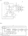
- the figure 1 illustrates an internal combustion engine 10 of the controlled ignition type (running in particular on gasoline) provided with a partial exhaust gas recirculation circuit called an EGR circuit (acronym for "exhaust gas recirculation") 20, a supercharging turbocharger 30 and variable valve timing VVT (an English acronym for “variable valve timing”,) respectively to the intake and to the exhaust 14,15 making it possible to modify the phasing of the opening of the valves in the cycle of engine combustion.
- EGR circuit an internal combustion engine 10 of the controlled ignition type (running in particular on gasoline) provided with a partial exhaust gas recirculation circuit called an EGR circuit (acronym for "exhaust gas recirculation") 20, a supercharging turbocharger 30 and variable valve timing VVT (an English acronym for “variable valve timing”,) respectively to the intake and to the exhaust 14,15 making it possible to modify the phasing of the opening of the valves in the cycle of engine combustion.
- VVT an English acronym for "variable valve timing”
- the engine is of the supercharged type.
- it may be an engine of the naturally aspirated type (atmospheric engine).
- the engine 10 comprises at least one cylinder 11 provided with intake valves 12 and exhaust valves 13 whose lift time is controlled respectively by a variable valve timing at the intake 14 and by a variable valve timing at exhaust 15.
- the intake valves 12 are connected to an intake manifold 16 fitted with a pressure sensor 16a and a temperature sensor 16b.
- the exhaust valves 13 are connected to an exhaust manifold 17 connected to the turbine 31 of the turbocharger 30.
- the outlet of the turbine 31 is connected to an exhaust pipe 17a provided with an oxygen sensor 17b used to determine the richness of the exhaust gases.
- the exhaust pipe 17a is generally provided with one or more treatment means (not shown in the figure) of the polluting species contained in the combustion gases emitted by the engine, for example a three-way catalyst, an oxide trap nitrogens, etc.
- a pipe 21 of an EGR circuit 20 is tapped upstream of the venting of the exhaust, for example downstream of the processing means.
- the EGR circuit 20 comprises an EGR flow valve 22 making it possible to control the EGR flow and can be equipped with a filter and/or a heat exchanger.
- the engine 10 is provided with a fresh air intake duct 40 comprising a vent at one of its ends, through which fresh air is taken from the outside atmosphere and then routed to the engine, generally through an air filter (not shown).
- This pipe 40 is connected by its other end to the compressor 32 of the turbocharger 30.
- the fresh air intake pipe 40 is also fitted with a flow meter 41 and a fresh air intake valve 42.
- the other end of pipe 21 of the EGR circuit is tapped onto fresh air intake pipe 40 between fresh air intake valve 42 and compressor 32 of the turbocharger.
- the EGR circuit is referred to as a low-pressure EGR circuit
- the engine in the case where the engine is of the naturally aspirated type, it does not have a turbocharger.
- the EGR circuit then generally originates downstream of the means for processing the exhaust pipe 17a, and its other end opens upstream of the engine.
- the output of the compressor 32 is connected to an intake pipe 50 leading to an intake valve 51, itself connected to the intake manifold 16.
- a discharge circuit provided with a discharge valve 33 is arranged in parallel compressor 32.
- the cylinders 11 are equipped with fuel injectors connected by at least one pump to a fuel tank.
- An electronic control unit 60 is connected at the input to the various sensors and probes and at the output to the various valves and control means so as to be able to control the internal combustion engine according to at least one control method.
- the electronic control unit 60 comprises a control system according to the invention.
- the control according to the invention consists in estimating the filling efficiency and in controlling its progressive increase up to the setpoint value determined according to the torque request of the driver, i.e. depressing the accelerator pedal.
- the command is iterative.
- the filling model is initialized at the first calculation step, with a predetermined filling efficiency value.
- the predetermined filling efficiency value is equal to a calibrated value of the filling efficiency ⁇ vol,cal , determined beforehand on a test bench and stored in a map.
- the predetermined fill yield value is equal to the last stored fill yield value.
- the canister purge flow rate Q CP corresponds to the mass flow rate of gas from the fuel tank, periodically purged into the gases admitted into the engine.
- the filling efficiency at the next step n+1 is then substituted for the previous determined value of the current step n.
- a final filling efficiency value ⁇ vol,fin is then defined taking into account the observed value ⁇ vol,obs and the mapped value ⁇ vol,cal of the filling efficiency.
- ⁇ flight , end ⁇ . ⁇ flight , ob + 1 ⁇ ⁇ ⁇ flight , callus
- the parameter ⁇ is a function of the convergence time of the filling efficiency.
- the value of the parameter ⁇ changes from a value of 0 at the start of the transient state to the value of 1 at the end of this state.
- the value of the parameter ⁇ is equal to 1. In this case, the calibrated value of the filling efficiency ⁇ vol,cal is not taken into account.
- the final filling efficiency ⁇ vol,fin thus calculated is used to modify the pressure set point in the manifold P col,sp , by correcting the estimated filling.
- the total engine flow setpoint Q tot,sp does not change and corresponds to the sum of the air flow setpoint Q air,sp and the EGR gas flow setpoint Q egr,sp that we want physically get into the engine.
- the total engine flow setpoint Q col,sp is linked to the manifold pressure P col and to the filling efficiency ⁇ vol by the filling model equation (Eq. 5). It is then understood that a modification of the filling efficiency ⁇ vol implies a modification of the pressure in the manifold P col . It is then possible to modify the pressure setpoint in the collector P coi,sp to control the motor and regulate it in closed loop according to the difference between the pressure measurement in the collector P col and the pressure setpoint in the collector P col, sp .
- a calculation means 101 determines the calibrated filling efficiency ⁇ vol,cal as a function of the rotational speed N of the engine, of the pressure measurement in the intake manifold P col and, when applicable, of the data of ignition advance of the VVT variable valve timing received as input and according to a stored map.
- a calculation means 103 determines the observed value of the total mass admitted into the cylinders m tot,obs as a function of the mass admitted into the engine m engine,est and the quantity of air admitted measured m AFS , the quantity of partially recirculated exhaust gases m EGR and canister purge mass m CP by application of an observer as described in equation Eq. 4.
- a calculation means 104 determines the observed value of the filling efficiency ⁇ vol,obs as a function of the observed value of the total mass admitted into the cylinders m tot,obs , of the temperature in the manifold T col , of the pressure in the collector P col and the volume of the cylinders V cyl by applying the equation Eq. 5.
- a calculation means 105 determines the final value of the filling efficiency ⁇ vol,fin as a function of the observed value of the filling efficiency ⁇ vol,obs and of the calibrated value of the filling efficiency ⁇ vol,cal , by applying the equation Eq. 6.
- a subtractor 106 determines the difference in filling efficiency ⁇ ⁇ vol between the final value ⁇ vol,fin and the calibrated value ⁇ vol,cal of the filling efficiency.
- a calculation means 107 saturates the filling efficiency difference ⁇ ⁇ vol so that the absolute value of the filling efficiency difference ⁇ ⁇ vol is less than 5% of the calibrated value of the filling efficiency ⁇ vol, cal .
- An adder 108 determines a filling efficiency setpoint ⁇ vol,sp by adding the saturated value ⁇ ⁇ vol,sat of the difference in filling efficiency and the calibrated value of the filling efficiency ⁇ vol,cal .
- the electronic control means of the internal combustion engine determines the pressure setpoint in the intake manifold P col,sp by applying the equation Eq. 8.
- the invention proposes the use of an observed filling efficiency to calculate the pressure set point in the manifold P col,sp , on the basis of an observed engine flow using all the data available, namely the EGR flow via the Barré Saint venant equation, the flowmeter measurement, and the filling model via the pressure in the manifold P col .
- control system can also be realized by control means such as those included in the electronic control unit in the form of process steps.
Landscapes
- Engineering & Computer Science (AREA)
- Chemical & Material Sciences (AREA)
- Combustion & Propulsion (AREA)
- Mechanical Engineering (AREA)
- General Engineering & Computer Science (AREA)
- Output Control And Ontrol Of Special Type Engine (AREA)
- Combined Controls Of Internal Combustion Engines (AREA)
- Electrical Control Of Ignition Timing (AREA)
Applications Claiming Priority (1)
| Application Number | Priority Date | Filing Date | Title |
|---|---|---|---|
| FR2013490A FR3118100B1 (fr) | 2020-12-17 | 2020-12-17 | Système et procédé de commande d’un moteur à combustion interne basée sur le rendement de remplissage |
Publications (2)
| Publication Number | Publication Date |
|---|---|
| EP4015808A1 true EP4015808A1 (de) | 2022-06-22 |
| EP4015808B1 EP4015808B1 (de) | 2024-08-28 |
Family
ID=74347437
Family Applications (1)
| Application Number | Title | Priority Date | Filing Date |
|---|---|---|---|
| EP21213233.6A Active EP4015808B1 (de) | 2020-12-17 | 2021-12-08 | Steuersystem und verfahren zur steuerung eines verbrennungsmotors, das auf dem wirkungsgrad der befüllung basiert |
Country Status (2)
| Country | Link |
|---|---|
| EP (1) | EP4015808B1 (de) |
| FR (1) | FR3118100B1 (de) |
Citations (4)
| Publication number | Priority date | Publication date | Assignee | Title |
|---|---|---|---|---|
| US5465617A (en) * | 1994-03-25 | 1995-11-14 | General Motors Corporation | Internal combustion engine control |
| EP2474728A1 (de) * | 2009-09-02 | 2012-07-11 | Toyota Jidosha Kabushiki Kaisha | Agr-steuersystem für einen verbrennungsmotor |
| US20140067287A1 (en) * | 2012-09-04 | 2014-03-06 | Hideki Hagari | Cylinder intake air amount estimation apparatus for internal combustion engine |
| EP3020940A1 (de) * | 2014-11-12 | 2016-05-18 | Deere & Company | Steuerungsverfahren und -system eines turboladers mit veränderlicher geometrie für ein motorluftsystem mit turbolader mit veränderlicher geometrie mit verstellbaren schaufeln |
-
2020
- 2020-12-17 FR FR2013490A patent/FR3118100B1/fr active Active
-
2021
- 2021-12-08 EP EP21213233.6A patent/EP4015808B1/de active Active
Patent Citations (4)
| Publication number | Priority date | Publication date | Assignee | Title |
|---|---|---|---|---|
| US5465617A (en) * | 1994-03-25 | 1995-11-14 | General Motors Corporation | Internal combustion engine control |
| EP2474728A1 (de) * | 2009-09-02 | 2012-07-11 | Toyota Jidosha Kabushiki Kaisha | Agr-steuersystem für einen verbrennungsmotor |
| US20140067287A1 (en) * | 2012-09-04 | 2014-03-06 | Hideki Hagari | Cylinder intake air amount estimation apparatus for internal combustion engine |
| EP3020940A1 (de) * | 2014-11-12 | 2016-05-18 | Deere & Company | Steuerungsverfahren und -system eines turboladers mit veränderlicher geometrie für ein motorluftsystem mit turbolader mit veränderlicher geometrie mit verstellbaren schaufeln |
Also Published As
| Publication number | Publication date |
|---|---|
| FR3118100A1 (fr) | 2022-06-24 |
| EP4015808B1 (de) | 2024-08-28 |
| FR3118100B1 (fr) | 2023-10-06 |
Similar Documents
| Publication | Publication Date | Title |
|---|---|---|
| CN110552799A (zh) | 一种废气再循环控制方法及装置 | |
| JP4173565B2 (ja) | 外部排気ガス再循環を有する内燃機関の負荷信号の決定方法 | |
| KR20200074520A (ko) | 액티브 퍼지 시스템에서의 퍼지 농도 산출 제어 방법 및 이를 이용한 연료량제어 방법 | |
| EP2956651B1 (de) | Verfarhen zur bestimmung des abgasdrucks stromaufwärts eines turboladers und der über dessen turbine fliessenden gasmenge | |
| EP2148979A2 (de) | Verfahren zur steuerung der verbrennung eines dieselmotors | |
| EP1590562B1 (de) | Verfahren zur steuerung von zur ausführung der grundfunktionen eines verbrennungsmotors verwendeten elementen | |
| EP4015808B1 (de) | Steuersystem und verfahren zur steuerung eines verbrennungsmotors, das auf dem wirkungsgrad der befüllung basiert | |
| EP1630387A1 (de) | Verfahren zur Steuerung der Abgasrückführmenge in einer Brennkraftmaschine eines Kraftfahrzeuges | |
| EP3995685B1 (de) | Verfahren zur diagnose eines luftdurchflussmessers für einen verbrennungsmotor | |
| FR2939475A1 (fr) | Procede anti-pollution avec correction de la courbe aeraulique de la vanne egr. | |
| CN113431690B (zh) | 一种发动机管理系统控制方法及装置 | |
| FR3085430A1 (fr) | Procede de calcul d'une position de consigne d'un turbocompresseur de moteur thermique | |
| EP2655838B1 (de) | System und verfahren zur steuerung eines verbrennungsmotors für ein kraftfahrzeug auf dem transportweg | |
| EP2256322B1 (de) | Einfluss der nox regelung auf die motorgeräuschregelung in einer brennkraftmaschine | |
| EP4222363B1 (de) | Verfahren zur bestimmung der masse von aspiriertem gas in einem zylinder unter berücksichtigung realer verwendungsbedingungen | |
| FR3115565A1 (fr) | Procédé et système de correction d’une mesure de débit d’air admis dans un moteur à combustion interne | |
| JP7690873B2 (ja) | エンジン制御装置 | |
| EP3004608B1 (de) | Verfahren zur messung des schadstoffausstosses eines verbrennungsmotors und verfahren zur steuerung des motors | |
| KR102187578B1 (ko) | 실린더 공기량 연산 방법 | |
| EP1519023B1 (de) | Prozess und Einrichtung zur Steuerung eines aufgeladenen, selbstzündenden Verbrennungsmotors für ein Fahrzeug | |
| FR3082887A1 (fr) | Procede de determination d’une consigne de puissance d’un compresseur de moteur a combustion interne | |
| FR2931892A1 (fr) | Procede d'estimation du debit de recirculation des gaz d'echappement sur un moteur bi-plenum avec volet de turbulence | |
| JP6292169B2 (ja) | 内燃機関の制御装置 | |
| EP4234909A1 (de) | Verfahren zur steuerung des gemischverhältnisses des kraftstoffgemischs einer brennkraftmaschine eines kraftfahrzeugs | |
| FR2829185A1 (fr) | Procede et dispositif de commande d'une soupape de reglage d'un flux de gaz d'echappement recircules dans le collecteur d'admission d'un moteur a combustion interne |
Legal Events
| Date | Code | Title | Description |
|---|---|---|---|
| PUAI | Public reference made under article 153(3) epc to a published international application that has entered the european phase |
Free format text: ORIGINAL CODE: 0009012 |
|
| STAA | Information on the status of an ep patent application or granted ep patent |
Free format text: STATUS: THE APPLICATION HAS BEEN PUBLISHED |
|
| AK | Designated contracting states |
Kind code of ref document: A1 Designated state(s): AL AT BE BG CH CY CZ DE DK EE ES FI FR GB GR HR HU IE IS IT LI LT LU LV MC MK MT NL NO PL PT RO RS SE SI SK SM TR |
|
| RAP3 | Party data changed (applicant data changed or rights of an application transferred) |
Owner name: RENAULT S.A.S |
|
| STAA | Information on the status of an ep patent application or granted ep patent |
Free format text: STATUS: REQUEST FOR EXAMINATION WAS MADE |
|
| 17P | Request for examination filed |
Effective date: 20221124 |
|
| RBV | Designated contracting states (corrected) |
Designated state(s): AL AT BE BG CH CY CZ DE DK EE ES FI FR GB GR HR HU IE IS IT LI LT LU LV MC MK MT NL NO PL PT RO RS SE SI SK SM TR |
|
| P01 | Opt-out of the competence of the unified patent court (upc) registered |
Effective date: 20230608 |
|
| RAP1 | Party data changed (applicant data changed or rights of an application transferred) |
Owner name: NEW H POWERTRAIN HOLDING, S.L.U. |
|
| GRAP | Despatch of communication of intention to grant a patent |
Free format text: ORIGINAL CODE: EPIDOSNIGR1 |
|
| STAA | Information on the status of an ep patent application or granted ep patent |
Free format text: STATUS: GRANT OF PATENT IS INTENDED |
|
| RIC1 | Information provided on ipc code assigned before grant |
Ipc: F02D 41/00 20060101ALN20240221BHEP Ipc: F02D 41/14 20060101ALI20240221BHEP Ipc: F02D 41/18 20060101AFI20240221BHEP |
|
| INTG | Intention to grant announced |
Effective date: 20240318 |
|
| GRAS | Grant fee paid |
Free format text: ORIGINAL CODE: EPIDOSNIGR3 |
|
| GRAA | (expected) grant |
Free format text: ORIGINAL CODE: 0009210 |
|
| STAA | Information on the status of an ep patent application or granted ep patent |
Free format text: STATUS: THE PATENT HAS BEEN GRANTED |
|
| AK | Designated contracting states |
Kind code of ref document: B1 Designated state(s): AL AT BE BG CH CY CZ DE DK EE ES FI FR GB GR HR HU IE IS IT LI LT LU LV MC MK MT NL NO PL PT RO RS SE SI SK SM TR |
|
| REG | Reference to a national code |
Ref country code: CH Ref legal event code: EP |
|
| REG | Reference to a national code |
Ref country code: DE Ref legal event code: R096 Ref document number: 602021017872 Country of ref document: DE |
|
| REG | Reference to a national code |
Ref country code: IE Ref legal event code: FG4D Free format text: LANGUAGE OF EP DOCUMENT: FRENCH |
|
| REG | Reference to a national code |
Ref country code: LT Ref legal event code: MG9D |
|
| PG25 | Lapsed in a contracting state [announced via postgrant information from national office to epo] |
Ref country code: NO Free format text: LAPSE BECAUSE OF FAILURE TO SUBMIT A TRANSLATION OF THE DESCRIPTION OR TO PAY THE FEE WITHIN THE PRESCRIBED TIME-LIMIT Effective date: 20241128 |
|
| REG | Reference to a national code |
Ref country code: AT Ref legal event code: MK05 Ref document number: 1718179 Country of ref document: AT Kind code of ref document: T Effective date: 20240828 |
|
| PG25 | Lapsed in a contracting state [announced via postgrant information from national office to epo] |
Ref country code: NL Free format text: LAPSE BECAUSE OF FAILURE TO SUBMIT A TRANSLATION OF THE DESCRIPTION OR TO PAY THE FEE WITHIN THE PRESCRIBED TIME-LIMIT Effective date: 20240828 Ref country code: PT Free format text: LAPSE BECAUSE OF FAILURE TO SUBMIT A TRANSLATION OF THE DESCRIPTION OR TO PAY THE FEE WITHIN THE PRESCRIBED TIME-LIMIT Effective date: 20241230 Ref country code: GR Free format text: LAPSE BECAUSE OF FAILURE TO SUBMIT A TRANSLATION OF THE DESCRIPTION OR TO PAY THE FEE WITHIN THE PRESCRIBED TIME-LIMIT Effective date: 20241129 Ref country code: PL Free format text: LAPSE BECAUSE OF FAILURE TO SUBMIT A TRANSLATION OF THE DESCRIPTION OR TO PAY THE FEE WITHIN THE PRESCRIBED TIME-LIMIT Effective date: 20240828 Ref country code: FI Free format text: LAPSE BECAUSE OF FAILURE TO SUBMIT A TRANSLATION OF THE DESCRIPTION OR TO PAY THE FEE WITHIN THE PRESCRIBED TIME-LIMIT Effective date: 20240828 |
|
| PG25 | Lapsed in a contracting state [announced via postgrant information from national office to epo] |
Ref country code: BG Free format text: LAPSE BECAUSE OF FAILURE TO SUBMIT A TRANSLATION OF THE DESCRIPTION OR TO PAY THE FEE WITHIN THE PRESCRIBED TIME-LIMIT Effective date: 20240828 |
|
| PG25 | Lapsed in a contracting state [announced via postgrant information from national office to epo] |
Ref country code: LV Free format text: LAPSE BECAUSE OF FAILURE TO SUBMIT A TRANSLATION OF THE DESCRIPTION OR TO PAY THE FEE WITHIN THE PRESCRIBED TIME-LIMIT Effective date: 20240828 |
|
| REG | Reference to a national code |
Ref country code: NL Ref legal event code: MP Effective date: 20240828 |
|
| PG25 | Lapsed in a contracting state [announced via postgrant information from national office to epo] |
Ref country code: IS Free format text: LAPSE BECAUSE OF FAILURE TO SUBMIT A TRANSLATION OF THE DESCRIPTION OR TO PAY THE FEE WITHIN THE PRESCRIBED TIME-LIMIT Effective date: 20241228 Ref country code: AT Free format text: LAPSE BECAUSE OF FAILURE TO SUBMIT A TRANSLATION OF THE DESCRIPTION OR TO PAY THE FEE WITHIN THE PRESCRIBED TIME-LIMIT Effective date: 20240828 |
|
| PG25 | Lapsed in a contracting state [announced via postgrant information from national office to epo] |
Ref country code: HR Free format text: LAPSE BECAUSE OF FAILURE TO SUBMIT A TRANSLATION OF THE DESCRIPTION OR TO PAY THE FEE WITHIN THE PRESCRIBED TIME-LIMIT Effective date: 20240828 |
|
| PG25 | Lapsed in a contracting state [announced via postgrant information from national office to epo] |
Ref country code: ES Free format text: LAPSE BECAUSE OF FAILURE TO SUBMIT A TRANSLATION OF THE DESCRIPTION OR TO PAY THE FEE WITHIN THE PRESCRIBED TIME-LIMIT Effective date: 20240828 Ref country code: RS Free format text: LAPSE BECAUSE OF FAILURE TO SUBMIT A TRANSLATION OF THE DESCRIPTION OR TO PAY THE FEE WITHIN THE PRESCRIBED TIME-LIMIT Effective date: 20241128 |
|
| PG25 | Lapsed in a contracting state [announced via postgrant information from national office to epo] |
Ref country code: RS Free format text: LAPSE BECAUSE OF FAILURE TO SUBMIT A TRANSLATION OF THE DESCRIPTION OR TO PAY THE FEE WITHIN THE PRESCRIBED TIME-LIMIT Effective date: 20241128 Ref country code: PT Free format text: LAPSE BECAUSE OF FAILURE TO SUBMIT A TRANSLATION OF THE DESCRIPTION OR TO PAY THE FEE WITHIN THE PRESCRIBED TIME-LIMIT Effective date: 20241230 Ref country code: PL Free format text: LAPSE BECAUSE OF FAILURE TO SUBMIT A TRANSLATION OF THE DESCRIPTION OR TO PAY THE FEE WITHIN THE PRESCRIBED TIME-LIMIT Effective date: 20240828 Ref country code: NO Free format text: LAPSE BECAUSE OF FAILURE TO SUBMIT A TRANSLATION OF THE DESCRIPTION OR TO PAY THE FEE WITHIN THE PRESCRIBED TIME-LIMIT Effective date: 20241128 Ref country code: NL Free format text: LAPSE BECAUSE OF FAILURE TO SUBMIT A TRANSLATION OF THE DESCRIPTION OR TO PAY THE FEE WITHIN THE PRESCRIBED TIME-LIMIT Effective date: 20240828 Ref country code: LV Free format text: LAPSE BECAUSE OF FAILURE TO SUBMIT A TRANSLATION OF THE DESCRIPTION OR TO PAY THE FEE WITHIN THE PRESCRIBED TIME-LIMIT Effective date: 20240828 Ref country code: IS Free format text: LAPSE BECAUSE OF FAILURE TO SUBMIT A TRANSLATION OF THE DESCRIPTION OR TO PAY THE FEE WITHIN THE PRESCRIBED TIME-LIMIT Effective date: 20241228 Ref country code: HR Free format text: LAPSE BECAUSE OF FAILURE TO SUBMIT A TRANSLATION OF THE DESCRIPTION OR TO PAY THE FEE WITHIN THE PRESCRIBED TIME-LIMIT Effective date: 20240828 Ref country code: GR Free format text: LAPSE BECAUSE OF FAILURE TO SUBMIT A TRANSLATION OF THE DESCRIPTION OR TO PAY THE FEE WITHIN THE PRESCRIBED TIME-LIMIT Effective date: 20241129 Ref country code: FI Free format text: LAPSE BECAUSE OF FAILURE TO SUBMIT A TRANSLATION OF THE DESCRIPTION OR TO PAY THE FEE WITHIN THE PRESCRIBED TIME-LIMIT Effective date: 20240828 Ref country code: ES Free format text: LAPSE BECAUSE OF FAILURE TO SUBMIT A TRANSLATION OF THE DESCRIPTION OR TO PAY THE FEE WITHIN THE PRESCRIBED TIME-LIMIT Effective date: 20240828 Ref country code: BG Free format text: LAPSE BECAUSE OF FAILURE TO SUBMIT A TRANSLATION OF THE DESCRIPTION OR TO PAY THE FEE WITHIN THE PRESCRIBED TIME-LIMIT Effective date: 20240828 Ref country code: AT Free format text: LAPSE BECAUSE OF FAILURE TO SUBMIT A TRANSLATION OF THE DESCRIPTION OR TO PAY THE FEE WITHIN THE PRESCRIBED TIME-LIMIT Effective date: 20240828 |
|
| PG25 | Lapsed in a contracting state [announced via postgrant information from national office to epo] |
Ref country code: RO Free format text: LAPSE BECAUSE OF FAILURE TO SUBMIT A TRANSLATION OF THE DESCRIPTION OR TO PAY THE FEE WITHIN THE PRESCRIBED TIME-LIMIT Effective date: 20240828 Ref country code: SM Free format text: LAPSE BECAUSE OF FAILURE TO SUBMIT A TRANSLATION OF THE DESCRIPTION OR TO PAY THE FEE WITHIN THE PRESCRIBED TIME-LIMIT Effective date: 20240828 Ref country code: DK Free format text: LAPSE BECAUSE OF FAILURE TO SUBMIT A TRANSLATION OF THE DESCRIPTION OR TO PAY THE FEE WITHIN THE PRESCRIBED TIME-LIMIT Effective date: 20240828 |
|
| PG25 | Lapsed in a contracting state [announced via postgrant information from national office to epo] |
Ref country code: EE Free format text: LAPSE BECAUSE OF FAILURE TO SUBMIT A TRANSLATION OF THE DESCRIPTION OR TO PAY THE FEE WITHIN THE PRESCRIBED TIME-LIMIT Effective date: 20240828 |
|
| PG25 | Lapsed in a contracting state [announced via postgrant information from national office to epo] |
Ref country code: CZ Free format text: LAPSE BECAUSE OF FAILURE TO SUBMIT A TRANSLATION OF THE DESCRIPTION OR TO PAY THE FEE WITHIN THE PRESCRIBED TIME-LIMIT Effective date: 20240828 |
|
| PG25 | Lapsed in a contracting state [announced via postgrant information from national office to epo] |
Ref country code: SK Free format text: LAPSE BECAUSE OF FAILURE TO SUBMIT A TRANSLATION OF THE DESCRIPTION OR TO PAY THE FEE WITHIN THE PRESCRIBED TIME-LIMIT Effective date: 20240828 Ref country code: IT Free format text: LAPSE BECAUSE OF FAILURE TO SUBMIT A TRANSLATION OF THE DESCRIPTION OR TO PAY THE FEE WITHIN THE PRESCRIBED TIME-LIMIT Effective date: 20240828 |
|
| REG | Reference to a national code |
Ref country code: DE Ref legal event code: R097 Ref document number: 602021017872 Country of ref document: DE |
|
| PLBE | No opposition filed within time limit |
Free format text: ORIGINAL CODE: 0009261 |
|
| STAA | Information on the status of an ep patent application or granted ep patent |
Free format text: STATUS: NO OPPOSITION FILED WITHIN TIME LIMIT |
|
| PG25 | Lapsed in a contracting state [announced via postgrant information from national office to epo] |
Ref country code: MC Free format text: LAPSE BECAUSE OF FAILURE TO SUBMIT A TRANSLATION OF THE DESCRIPTION OR TO PAY THE FEE WITHIN THE PRESCRIBED TIME-LIMIT Effective date: 20240828 |
|
| REG | Reference to a national code |
Ref country code: CH Ref legal event code: PL |
|
| 26N | No opposition filed |
Effective date: 20250530 |
|
| PG25 | Lapsed in a contracting state [announced via postgrant information from national office to epo] |
Ref country code: LU Free format text: LAPSE BECAUSE OF NON-PAYMENT OF DUE FEES Effective date: 20241208 |
|
| PG25 | Lapsed in a contracting state [announced via postgrant information from national office to epo] |
Ref country code: SE Free format text: LAPSE BECAUSE OF FAILURE TO SUBMIT A TRANSLATION OF THE DESCRIPTION OR TO PAY THE FEE WITHIN THE PRESCRIBED TIME-LIMIT Effective date: 20240828 |
|
| REG | Reference to a national code |
Ref country code: BE Ref legal event code: MM Effective date: 20241231 |
|
| PG25 | Lapsed in a contracting state [announced via postgrant information from national office to epo] |
Ref country code: BE Free format text: LAPSE BECAUSE OF NON-PAYMENT OF DUE FEES Effective date: 20241231 |
|
| PG25 | Lapsed in a contracting state [announced via postgrant information from national office to epo] |
Ref country code: CH Free format text: LAPSE BECAUSE OF NON-PAYMENT OF DUE FEES Effective date: 20241231 |
|
| PG25 | Lapsed in a contracting state [announced via postgrant information from national office to epo] |
Ref country code: IE Free format text: LAPSE BECAUSE OF NON-PAYMENT OF DUE FEES Effective date: 20241208 |
|
| PGFP | Annual fee paid to national office [announced via postgrant information from national office to epo] |
Ref country code: DE Payment date: 20251211 Year of fee payment: 5 |
|
| PGFP | Annual fee paid to national office [announced via postgrant information from national office to epo] |
Ref country code: GB Payment date: 20251219 Year of fee payment: 5 |
|
| PGFP | Annual fee paid to national office [announced via postgrant information from national office to epo] |
Ref country code: FR Payment date: 20251229 Year of fee payment: 5 |