EP4015919A1 - Système de détection d'une obstruction dans le circuit de chauffage central - Google Patents
Système de détection d'une obstruction dans le circuit de chauffage central Download PDFInfo
- Publication number
- EP4015919A1 EP4015919A1 EP21212725.2A EP21212725A EP4015919A1 EP 4015919 A1 EP4015919 A1 EP 4015919A1 EP 21212725 A EP21212725 A EP 21212725A EP 4015919 A1 EP4015919 A1 EP 4015919A1
- Authority
- EP
- European Patent Office
- Prior art keywords
- central heating
- heating circuit
- water
- pump
- temperature sensor
- Prior art date
- Legal status (The legal status is an assumption and is not a legal conclusion. Google has not performed a legal analysis and makes no representation as to the accuracy of the status listed.)
- Granted
Links
Images
Classifications
-
- F—MECHANICAL ENGINEERING; LIGHTING; HEATING; WEAPONS; BLASTING
- F24—HEATING; RANGES; VENTILATING
- F24D—DOMESTIC- OR SPACE-HEATING SYSTEMS, e.g. CENTRAL HEATING SYSTEMS; DOMESTIC HOT-WATER SUPPLY SYSTEMS; ELEMENTS OR COMPONENTS THEREFOR
- F24D19/00—Details
- F24D19/0092—Devices for preventing or removing corrosion, slime or scale
-
- F—MECHANICAL ENGINEERING; LIGHTING; HEATING; WEAPONS; BLASTING
- F24—HEATING; RANGES; VENTILATING
- F24D—DOMESTIC- OR SPACE-HEATING SYSTEMS, e.g. CENTRAL HEATING SYSTEMS; DOMESTIC HOT-WATER SUPPLY SYSTEMS; ELEMENTS OR COMPONENTS THEREFOR
- F24D19/00—Details
- F24D19/10—Arrangement or mounting of control or safety devices
- F24D19/1006—Arrangement or mounting of control or safety devices for water heating systems
- F24D19/1009—Arrangement or mounting of control or safety devices for water heating systems for central heating
- F24D19/1012—Arrangement or mounting of control or safety devices for water heating systems for central heating by regulating the speed of a pump
-
- F—MECHANICAL ENGINEERING; LIGHTING; HEATING; WEAPONS; BLASTING
- F24—HEATING; RANGES; VENTILATING
- F24H—FLUID HEATERS, e.g. WATER OR AIR HEATERS, HAVING HEAT-GENERATING MEANS, e.g. HEAT PUMPS, IN GENERAL
- F24H15/00—Control of fluid heaters
- F24H15/10—Control of fluid heaters characterised by the purpose of the control
- F24H15/104—Inspection; Diagnosis; Trial operation
-
- F—MECHANICAL ENGINEERING; LIGHTING; HEATING; WEAPONS; BLASTING
- F24—HEATING; RANGES; VENTILATING
- F24H—FLUID HEATERS, e.g. WATER OR AIR HEATERS, HAVING HEAT-GENERATING MEANS, e.g. HEAT PUMPS, IN GENERAL
- F24H15/00—Control of fluid heaters
- F24H15/20—Control of fluid heaters characterised by control inputs
- F24H15/212—Temperature of the water
- F24H15/215—Temperature of the water before heating
-
- F—MECHANICAL ENGINEERING; LIGHTING; HEATING; WEAPONS; BLASTING
- F24—HEATING; RANGES; VENTILATING
- F24H—FLUID HEATERS, e.g. WATER OR AIR HEATERS, HAVING HEAT-GENERATING MEANS, e.g. HEAT PUMPS, IN GENERAL
- F24H15/00—Control of fluid heaters
- F24H15/20—Control of fluid heaters characterised by control inputs
- F24H15/212—Temperature of the water
- F24H15/219—Temperature of the water after heating
-
- F—MECHANICAL ENGINEERING; LIGHTING; HEATING; WEAPONS; BLASTING
- F24—HEATING; RANGES; VENTILATING
- F24H—FLUID HEATERS, e.g. WATER OR AIR HEATERS, HAVING HEAT-GENERATING MEANS, e.g. HEAT PUMPS, IN GENERAL
- F24H15/00—Control of fluid heaters
- F24H15/20—Control of fluid heaters characterised by control inputs
- F24H15/238—Flow rate
-
- F—MECHANICAL ENGINEERING; LIGHTING; HEATING; WEAPONS; BLASTING
- F24—HEATING; RANGES; VENTILATING
- F24H—FLUID HEATERS, e.g. WATER OR AIR HEATERS, HAVING HEAT-GENERATING MEANS, e.g. HEAT PUMPS, IN GENERAL
- F24H15/00—Control of fluid heaters
- F24H15/20—Control of fluid heaters characterised by control inputs
- F24H15/288—Accumulation of deposits, e.g. lime or scale
-
- F—MECHANICAL ENGINEERING; LIGHTING; HEATING; WEAPONS; BLASTING
- F24—HEATING; RANGES; VENTILATING
- F24H—FLUID HEATERS, e.g. WATER OR AIR HEATERS, HAVING HEAT-GENERATING MEANS, e.g. HEAT PUMPS, IN GENERAL
- F24H15/00—Control of fluid heaters
- F24H15/30—Control of fluid heaters characterised by control outputs; characterised by the components to be controlled
- F24H15/335—Control of pumps, e.g. on-off control
- F24H15/34—Control of the speed of pumps
-
- F—MECHANICAL ENGINEERING; LIGHTING; HEATING; WEAPONS; BLASTING
- F24—HEATING; RANGES; VENTILATING
- F24H—FLUID HEATERS, e.g. WATER OR AIR HEATERS, HAVING HEAT-GENERATING MEANS, e.g. HEAT PUMPS, IN GENERAL
- F24H15/00—Control of fluid heaters
- F24H15/40—Control of fluid heaters characterised by the type of controllers
- F24H15/414—Control of fluid heaters characterised by the type of controllers using electronic processing, e.g. computer-based
- F24H15/45—Control of fluid heaters characterised by the type of controllers using electronic processing, e.g. computer-based remotely accessible
- F24H15/464—Control of fluid heaters characterised by the type of controllers using electronic processing, e.g. computer-based remotely accessible using local wireless communication
-
- Y—GENERAL TAGGING OF NEW TECHNOLOGICAL DEVELOPMENTS; GENERAL TAGGING OF CROSS-SECTIONAL TECHNOLOGIES SPANNING OVER SEVERAL SECTIONS OF THE IPC; TECHNICAL SUBJECTS COVERED BY FORMER USPC CROSS-REFERENCE ART COLLECTIONS [XRACs] AND DIGESTS
- Y02—TECHNOLOGIES OR APPLICATIONS FOR MITIGATION OR ADAPTATION AGAINST CLIMATE CHANGE
- Y02B—CLIMATE CHANGE MITIGATION TECHNOLOGIES RELATED TO BUILDINGS, e.g. HOUSING, HOUSE APPLIANCES OR RELATED END-USER APPLICATIONS
- Y02B30/00—Energy efficient heating, ventilation or air conditioning [HVAC]
- Y02B30/70—Efficient control or regulation technologies, e.g. for control of refrigerant flow, motor or heating
Definitions
- the invention relates to a system and a water heater comprising this system for detecting an at least partial blockage in a central heating circuit of a water heater, comprising a first pipe, a heating cell for heating the water flowing through the heating zone of said first pipe, a pump for pumping the water into said first line, the central heating circuit comprising said first line and a central heating circuit connected to the first line to form a closed circuit.
- Water heaters are connected to a central heating circuit.
- the liquid in the circuit is heated upon introduction into the water heater, the heated water is fed into the central heating circuit and is cooled by passing through central heating components in the central heating circuit such as the radiator, giving up its heat to the zone where the central heating elements are located and is fed back into the water heater after completing the cycle.
- the pipes and central heating components in the central heating circuit can become clogged over time due to substances produced by interaction with various particles, water and air, etc., or other factors.
- the blockage results in reduced heating of the zone by the central heating components. This in turn results in the user not noticing the clogging that develops over time and use at low capacity for a longer period of time. This can lead to an increase in energy consumption.
- the present invention relates to a system for eliminating the above-mentioned disadvantages and for obtaining new advantages in the relevant technical field.
- An object of the invention is to provide a system that allows blockages in the central heating circuit to be detected.
- a further object of the invention is to provide a system which enables blockages in the central heating circuit to be detected earlier than the prior art systems.
- Another object of the invention is to provide a preventive system that allows at least partially to increase the life of the components of the water heaters.
- a further object of the invention is to provide a system which makes it possible to at least partially unblock the central heating circuit.
- the feature of a possible embodiment of the invention is that it comprises a user interface controlled by the control unit for sending the generated signal to the user. This ensures that the user is informed of the blockage.
- control unit is configured to control the pump so that the water in the central heating circuit flows turbulently. Due to the turbulent flow in the central heating circuit, the water exerts a cutting force on the sides, ensuring that the clogging particles are at least partially dislodged from the pipe surface.
- the feature of another possible embodiment of the invention is that the mentioned user interface is provided on the water heater.
- the mentioned user interface is located remotely from the water heater and is configured to communicate wirelessly with the control unit.
- said user interface is provided on an electronic terminal and configured to communicate wirelessly with the control unit.
- the feature of a further possible embodiment of the invention is that the mentioned flow measuring device is provided in the first line.
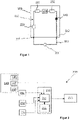
- the invention relates to a system (200) for detecting an at least partial blockage in a central heating circuit of a water heater (100), comprising a first line (110), a heating cell (130) for heating the water flowing through the heating zone of said first line (110). water, a pump (140) for pumping the water in said first line (110), the central heating circuit comprising said first line (110) and a central heating circuit (310) so connected to the first line (110), that they form a closed circuit.
- the central heating circuit mentioned here comprises a first line (110) provided in the water heater (100) and a central heating circuit (310) in which the liquid which has been heated in the first line (110) and exits the first line (110) circulates.
- the central heating circuit (310) may include central heating components such as ducts and radiators.
- the water heater (100) can be a combination water heater as in 3 be. In other words, it is ensured both that warm water circulates in the central heating circuit and that the water in a domestic water pipe (320) is heated.
- the domestic water line (320) is assigned to a heat exchanger, which in turn is connected via a valve in the water heater (100) to the second line (120), which separates from the first line (110). The heated water heats the water in the domestic water line (320) in the heat exchanger via the second line (120).
- the object of the invention is to detect a slowdown in flow due to a blockage in the central heating circuit, in other words the blockage in the central heating circuit.
- the system (200) comprises a flow measuring device (220) for measuring the volume flow of the liquid in the central heating circuit.
- the flow measuring device (220) can be arranged in the first line (110) of the water heater (100).
- the system (200) includes a first temperature sensor (231) for measuring the temperature of the water exiting the heating zone. Said first temperature sensor (231) is provided between a central heating supply head (111), a first pipe (110) through which the heated water coming out of the first pipe (110) is fed into the central heating circuit (310) and a heating cell (130).
- a second temperature sensor (232) is provided to measure the temperature of the water about to flow into the heating zone.
- Said temperature sensor is provided between a central heating return head (112) of the first line, which ensures that the water circulates in the central heating circuit (310) and is returned to the first line (110), and the heating cell (130).
- the pump (140) can also be provided between the heating cell (130) and the central heating return head (112).
- the system comprises at least one of a current measuring device (141) for measuring the current flowing from an electric point of the pump (140), an energy consumption measuring device for measuring the electric energy consumed by the pump (140), or a tachometer (143) for measuring the revolutions a vane of the pump (140) over time.
- the system (200) can include all these measuring devices at once.
- these means are components integrated into the pump (140).
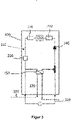
- the system includes a control unit (210) configured to receive the measurements from the first temperature sensor (231), the second temperature sensor (232) and the flow meter (220).
- the control unit (210) is also configured to control the pump (140).
- the control unit (210) is also electrically connected to the energy consumption measuring device (142), the current measuring device (141) and the tachometer (143) so that it receives measurements from at least one of these components.
- the control unit (210) includes a processor unit (211).
- the control unit (210) also comprises a processor unit (211) which is assigned to it in such a way that it reads data and records data.
- the processor unit (211) stores the measurements received from the sensors and the measuring devices in the memory unit (212) by associating them with their reception times.
- the processor unit (211) can be a processor, the storage unit (212) can be a memory that permanently stores the data.
- the memory unit (212), when driven by the processor unit (211), may comprise software consisting of command lines that ensure that the steps that ensure the innovative aspect of the system (200) according to the invention are implemented are carried out will.
- the system may include a user interface (250) for providing information to the user.
- Said user interface (250) can be a screen.
- the user interface (250) can be on the water heater (100) or remote from the water heater (100) and arranged to communicate wirelessly with the processor unit (211):
- the user interface (250) can also be provided on a mobile electronic terminal.
- the control unit (210) may also include a communications interface for sending congestion signals to a server.
- the first maximum value mentioned here means the highest current value obtainable from the mentioned point of the pump under normal circumstances
- the second maximum value means the highest energy value that the pump could consume under normal circumstances
- the third maximum value means the highest speed that the pump impeller of the pump can operate under can achieve under normal circumstances. Normal circumstances are circumstances where a properly functioning water heater uses the pump to provide central heating.
- the processing unit determines the increasing trend and decreasing trend as follows:
- the processing unit (211) recognizes the increasing trend when it determines that the initial and final values of a predetermined number of monitored measurements are in a first range of values, which are sequentially above the initial and final values of a normal range of values and detects the decreasing trend when it finds that the beginning and ending values of a predetermined number of monitored measurements are within a first range of values which are sequentially below the beginning and end of a normal range of values.
- the increasing trend can be detected when it is determined that the majority of consecutive measurements are increasing according to time and that they are above certain thresholds; the decrease trend can be recognized when it is found that the majority of the consecutive measurements decreases and that it is below certain thresholds.
- the increasing or decreasing trend can be recognized by considering the maximum and/or minimum values observed in certain intervals.
- the liquid will flow through the circuit for a longer period of time and less water will flow when there is a blockage in the central heating circuit, the liquid will experience more heat loss. In addition, the liquid stays longer in the heating zone as the flow rate decreases and the temperature of the water exiting the water heater (100) increases. This results in a larger difference between the temperatures of the liquid exiting the heating zone and the liquid circulating in the central heating circuit and flowing back to the heating zone.
- the flow sensor detects that the flow of liquid slows down over time. Since the pump (140) operating at maximum values shows that there is no physical obstruction to the pump (140) revolutions, under the above circumstances it is recognized that there is a blockage in the central heating circuit.
- control unit (210) can divide the congestion into categories according to the size of the increasing trend and decreasing trend.
- the controller (210) is configured to operate the pump (140) in the event of an obstruction in the first volume such that the liquid in the first volume flows turbulently. Due to the turbulent flow, the liquid particles increasingly exert a cutting force on the sides of the pipe through non-linear movements (spiral or similar). This in turn ensures that unwanted particles on the pipe surface causing clogging are dislodged from the pipe surface and the pipe surface is cleaned.
- the monitoring must take place over a certain period of time.
- the monitoring can be longer than 30 days. Since the constipation does not occur suddenly but occurs over time, with longer monitoring, the increase trend and the decrease trend caused by the constipation can be recognized.
- the states of the central heating components must be maintained. For example, all radiators must be on. Because the monitoring takes place over time, instantaneous measurement errors are prevented or measurements that occur from instantaneous events lead to errors in the detection of blockages.
Landscapes
- Engineering & Computer Science (AREA)
- Physics & Mathematics (AREA)
- Thermal Sciences (AREA)
- Chemical & Material Sciences (AREA)
- Combustion & Propulsion (AREA)
- Mechanical Engineering (AREA)
- General Engineering & Computer Science (AREA)
- Fluid Mechanics (AREA)
- Health & Medical Sciences (AREA)
- Biomedical Technology (AREA)
- Measuring Volume Flow (AREA)
- Steam Or Hot-Water Central Heating Systems (AREA)
Applications Claiming Priority (1)
| Application Number | Priority Date | Filing Date | Title |
|---|---|---|---|
| TR2020/20592A TR202020592A2 (tr) | 2020-12-15 | 2020-12-15 | Merkezi̇ isitma çevri̇mi̇ndeki̇ tikanikliği tespi̇t etmek i̇çi̇n bi̇r si̇stem |
Publications (2)
| Publication Number | Publication Date |
|---|---|
| EP4015919A1 true EP4015919A1 (fr) | 2022-06-22 |
| EP4015919B1 EP4015919B1 (fr) | 2025-06-18 |
Family
ID=75575841
Family Applications (1)
| Application Number | Title | Priority Date | Filing Date |
|---|---|---|---|
| EP21212725.2A Active EP4015919B1 (fr) | 2020-12-15 | 2021-12-07 | Système de détection d'obstruction dans un circuit de chauffage central |
Country Status (2)
| Country | Link |
|---|---|
| EP (1) | EP4015919B1 (fr) |
| TR (1) | TR202020592A2 (fr) |
Cited By (2)
| Publication number | Priority date | Publication date | Assignee | Title |
|---|---|---|---|---|
| CN114353339A (zh) * | 2020-09-29 | 2022-04-15 | 芜湖美的厨卫电器制造有限公司 | 加热控制方法、燃气热水器和计算机可读存储介质 |
| IT202400004822A1 (it) * | 2024-03-05 | 2025-09-05 | Ariston Spa | Metodo per la manutenzione predittiva di uno scambiatore di calore in una caldaia |
Citations (4)
| Publication number | Priority date | Publication date | Assignee | Title |
|---|---|---|---|---|
| JP2009250461A (ja) * | 2008-04-02 | 2009-10-29 | Panasonic Corp | ヒートポンプ給湯装置 |
| JP2010091181A (ja) * | 2008-10-08 | 2010-04-22 | Corona Corp | 貯湯式給湯暖房装置およびヒートポンプ給湯装置 |
| EP2966367A1 (fr) * | 2014-07-07 | 2016-01-13 | Mitsubishi Electric Corporation | Appareil à eau chaude et procédé de notification de défaillance pour appareil à eau chaude |
| EP3260794A1 (fr) * | 2015-02-20 | 2017-12-27 | Mitsubishi Electric Corporation | Dispositif d'échange de chaleur et chauffe eau à pompe à chaleur |
-
2020
- 2020-12-15 TR TR2020/20592A patent/TR202020592A2/tr unknown
-
2021
- 2021-12-07 EP EP21212725.2A patent/EP4015919B1/fr active Active
Patent Citations (4)
| Publication number | Priority date | Publication date | Assignee | Title |
|---|---|---|---|---|
| JP2009250461A (ja) * | 2008-04-02 | 2009-10-29 | Panasonic Corp | ヒートポンプ給湯装置 |
| JP2010091181A (ja) * | 2008-10-08 | 2010-04-22 | Corona Corp | 貯湯式給湯暖房装置およびヒートポンプ給湯装置 |
| EP2966367A1 (fr) * | 2014-07-07 | 2016-01-13 | Mitsubishi Electric Corporation | Appareil à eau chaude et procédé de notification de défaillance pour appareil à eau chaude |
| EP3260794A1 (fr) * | 2015-02-20 | 2017-12-27 | Mitsubishi Electric Corporation | Dispositif d'échange de chaleur et chauffe eau à pompe à chaleur |
Cited By (3)
| Publication number | Priority date | Publication date | Assignee | Title |
|---|---|---|---|---|
| CN114353339A (zh) * | 2020-09-29 | 2022-04-15 | 芜湖美的厨卫电器制造有限公司 | 加热控制方法、燃气热水器和计算机可读存储介质 |
| IT202400004822A1 (it) * | 2024-03-05 | 2025-09-05 | Ariston Spa | Metodo per la manutenzione predittiva di uno scambiatore di calore in una caldaia |
| WO2025186610A1 (fr) * | 2024-03-05 | 2025-09-12 | Ariston S.P.A. | Procédé pour la maintenance prédictive d'un échangeur de chaleur de chaudière |
Also Published As
| Publication number | Publication date |
|---|---|
| EP4015919B1 (fr) | 2025-06-18 |
| TR202020592A2 (tr) | 2021-01-21 |
Similar Documents
| Publication | Publication Date | Title |
|---|---|---|
| DE102017111976B4 (de) | Motorkühlmittelsystem zur erfassung eines kühlmittellecks durch auswertung der elektrischen signale einer kühlmittelpumpe | |
| EP2080461B1 (fr) | Dispositif et procédé de détermination d'un état d'entartrage dans un appareil ménager électrique | |
| EP3014373B1 (fr) | Système d'estimation de la durée de vie d'un moteur électrique | |
| EP4015919B1 (fr) | Système de détection d'obstruction dans un circuit de chauffage central | |
| EP2293027B1 (fr) | Procédé d'estimation du danger potentiel d'une contamination microbienne à l'aide d'un débitmètre | |
| DE102007014810B3 (de) | Energiezähler und Verfahren zur Erfassung einer Wärme- oder Kältemenge | |
| EP3569989B1 (fr) | Compteur de fluide | |
| EP2908059A1 (fr) | Procédé de diagnostic d'une installation de chauffage doté d'au moins un échangeur thermique | |
| EP2657803B1 (fr) | Installation et procédé de réglage de la température ambiante pour pièces chauffées à l'eau chaude | |
| EP3901550B1 (fr) | Système de détection de blocage dans un échangeur de chaleur | |
| EP4206554A1 (fr) | Système pour déterminer la durée de vie résiduelle d'un échangeur de chaleur de chauffe-eau | |
| DE102020109222A1 (de) | Verfahren zur Überwachung einer Pumpe | |
| EP2327971B1 (fr) | Procédé d'analyse de la répartition des quantités de chaleur dans un système de chauffage et dispositif d'exécution du procédé | |
| EP0676682B1 (fr) | Capteur solaire avec surveillance de panne | |
| EP3844398B1 (fr) | Procédé de détection de l'état de fonctionnement d'une machine tournante | |
| EP3896360B1 (fr) | Système de détection d'un blocage dans l'échangeur de chaleur | |
| EP4256243A1 (fr) | Procédé de fonctionnement d'un système de chauffage | |
| WO2013087153A1 (fr) | Procédé et dispositif de surveillance d'un système d'acheminement d'un fluide | |
| EP3377771B1 (fr) | Commutation d'une pompe en fonction du débit, ledit débit étant détecté par un débimètre thermique | |
| EP4036484B1 (fr) | Installation de chauffage et procédé de fonctionnement d'une installation de chauffage | |
| EP4015977B1 (fr) | Système et méthode pour éliminer les obstructions dans le chauffe-eau | |
| DE102017112505A1 (de) | Verfahren zum Betreiben eines thermischen Verbrauchssystems | |
| EP2551604A1 (fr) | Installation solaire | |
| DE102016011699A1 (de) | Kühlvorrichtung mit einer Funktion zum Erfassen des Verstopfens von Abstrahlrippen | |
| DE102017200014A1 (de) | Elektromotor |
Legal Events
| Date | Code | Title | Description |
|---|---|---|---|
| PUAI | Public reference made under article 153(3) epc to a published international application that has entered the european phase |
Free format text: ORIGINAL CODE: 0009012 |
|
| STAA | Information on the status of an ep patent application or granted ep patent |
Free format text: STATUS: THE APPLICATION HAS BEEN PUBLISHED |
|
| AK | Designated contracting states |
Kind code of ref document: A1 Designated state(s): AL AT BE BG CH CY CZ DE DK EE ES FI FR GB GR HR HU IE IS IT LI LT LU LV MC MK MT NL NO PL PT RO RS SE SI SK SM TR |
|
| STAA | Information on the status of an ep patent application or granted ep patent |
Free format text: STATUS: REQUEST FOR EXAMINATION WAS MADE |
|
| 17P | Request for examination filed |
Effective date: 20221222 |
|
| RBV | Designated contracting states (corrected) |
Designated state(s): AL AT BE BG CH CY CZ DE DK EE ES FI FR GB GR HR HU IE IS IT LI LT LU LV MC MK MT NL NO PL PT RO RS SE SI SK SM TR |
|
| GRAP | Despatch of communication of intention to grant a patent |
Free format text: ORIGINAL CODE: EPIDOSNIGR1 |
|
| STAA | Information on the status of an ep patent application or granted ep patent |
Free format text: STATUS: GRANT OF PATENT IS INTENDED |
|
| INTG | Intention to grant announced |
Effective date: 20250206 |
|
| GRAS | Grant fee paid |
Free format text: ORIGINAL CODE: EPIDOSNIGR3 |
|
| GRAA | (expected) grant |
Free format text: ORIGINAL CODE: 0009210 |
|
| STAA | Information on the status of an ep patent application or granted ep patent |
Free format text: STATUS: THE PATENT HAS BEEN GRANTED |
|
| AK | Designated contracting states |
Kind code of ref document: B1 Designated state(s): AL AT BE BG CH CY CZ DE DK EE ES FI FR GB GR HR HU IE IS IT LI LT LU LV MC MK MT NL NO PL PT RO RS SE SI SK SM TR |
|
| REG | Reference to a national code |
Ref country code: GB Ref legal event code: FG4D Free format text: NOT ENGLISH |
|
| REG | Reference to a national code |
Ref country code: CH Ref legal event code: EP |
|
| REG | Reference to a national code |
Ref country code: DE Ref legal event code: R096 Ref document number: 502021007770 Country of ref document: DE |
|
| REG | Reference to a national code |
Ref country code: CH Ref legal event code: EP |
|
| REG | Reference to a national code |
Ref country code: IE Ref legal event code: FG4D Free format text: LANGUAGE OF EP DOCUMENT: GERMAN |
|
| PG25 | Lapsed in a contracting state [announced via postgrant information from national office to epo] |
Ref country code: FI Free format text: LAPSE BECAUSE OF FAILURE TO SUBMIT A TRANSLATION OF THE DESCRIPTION OR TO PAY THE FEE WITHIN THE PRESCRIBED TIME-LIMIT Effective date: 20250618 |
|
| REG | Reference to a national code |
Ref country code: LT Ref legal event code: MG9D |
|
| PG25 | Lapsed in a contracting state [announced via postgrant information from national office to epo] |
Ref country code: GR Free format text: LAPSE BECAUSE OF FAILURE TO SUBMIT A TRANSLATION OF THE DESCRIPTION OR TO PAY THE FEE WITHIN THE PRESCRIBED TIME-LIMIT Effective date: 20250919 Ref country code: NO Free format text: LAPSE BECAUSE OF FAILURE TO SUBMIT A TRANSLATION OF THE DESCRIPTION OR TO PAY THE FEE WITHIN THE PRESCRIBED TIME-LIMIT Effective date: 20250918 |
|
| PG25 | Lapsed in a contracting state [announced via postgrant information from national office to epo] |
Ref country code: BG Free format text: LAPSE BECAUSE OF FAILURE TO SUBMIT A TRANSLATION OF THE DESCRIPTION OR TO PAY THE FEE WITHIN THE PRESCRIBED TIME-LIMIT Effective date: 20250618 |
|
| PG25 | Lapsed in a contracting state [announced via postgrant information from national office to epo] |
Ref country code: HR Free format text: LAPSE BECAUSE OF FAILURE TO SUBMIT A TRANSLATION OF THE DESCRIPTION OR TO PAY THE FEE WITHIN THE PRESCRIBED TIME-LIMIT Effective date: 20250618 |
|
| PG25 | Lapsed in a contracting state [announced via postgrant information from national office to epo] |
Ref country code: RS Free format text: LAPSE BECAUSE OF FAILURE TO SUBMIT A TRANSLATION OF THE DESCRIPTION OR TO PAY THE FEE WITHIN THE PRESCRIBED TIME-LIMIT Effective date: 20250918 |
|
| REG | Reference to a national code |
Ref country code: NL Ref legal event code: MP Effective date: 20250618 |
|
| PG25 | Lapsed in a contracting state [announced via postgrant information from national office to epo] |
Ref country code: LV Free format text: LAPSE BECAUSE OF FAILURE TO SUBMIT A TRANSLATION OF THE DESCRIPTION OR TO PAY THE FEE WITHIN THE PRESCRIBED TIME-LIMIT Effective date: 20250618 |
|
| PG25 | Lapsed in a contracting state [announced via postgrant information from national office to epo] |
Ref country code: NL Free format text: LAPSE BECAUSE OF FAILURE TO SUBMIT A TRANSLATION OF THE DESCRIPTION OR TO PAY THE FEE WITHIN THE PRESCRIBED TIME-LIMIT Effective date: 20250618 |
|
| PG25 | Lapsed in a contracting state [announced via postgrant information from national office to epo] |
Ref country code: PT Free format text: LAPSE BECAUSE OF FAILURE TO SUBMIT A TRANSLATION OF THE DESCRIPTION OR TO PAY THE FEE WITHIN THE PRESCRIBED TIME-LIMIT Effective date: 20251020 |
|
| PG25 | Lapsed in a contracting state [announced via postgrant information from national office to epo] |
Ref country code: IS Free format text: LAPSE BECAUSE OF FAILURE TO SUBMIT A TRANSLATION OF THE DESCRIPTION OR TO PAY THE FEE WITHIN THE PRESCRIBED TIME-LIMIT Effective date: 20251018 |
|
| PG25 | Lapsed in a contracting state [announced via postgrant information from national office to epo] |
Ref country code: SM Free format text: LAPSE BECAUSE OF FAILURE TO SUBMIT A TRANSLATION OF THE DESCRIPTION OR TO PAY THE FEE WITHIN THE PRESCRIBED TIME-LIMIT Effective date: 20250618 |
|
| PGFP | Annual fee paid to national office [announced via postgrant information from national office to epo] |
Ref country code: AT Payment date: 20260113 Year of fee payment: 5 |
|
| PG25 | Lapsed in a contracting state [announced via postgrant information from national office to epo] |
Ref country code: CZ Free format text: LAPSE BECAUSE OF FAILURE TO SUBMIT A TRANSLATION OF THE DESCRIPTION OR TO PAY THE FEE WITHIN THE PRESCRIBED TIME-LIMIT Effective date: 20250618 |
|
| PG25 | Lapsed in a contracting state [announced via postgrant information from national office to epo] |
Ref country code: PL Free format text: LAPSE BECAUSE OF FAILURE TO SUBMIT A TRANSLATION OF THE DESCRIPTION OR TO PAY THE FEE WITHIN THE PRESCRIBED TIME-LIMIT Effective date: 20250618 |
|
| PG25 | Lapsed in a contracting state [announced via postgrant information from national office to epo] |
Ref country code: EE Free format text: LAPSE BECAUSE OF FAILURE TO SUBMIT A TRANSLATION OF THE DESCRIPTION OR TO PAY THE FEE WITHIN THE PRESCRIBED TIME-LIMIT Effective date: 20250618 |
|
| PG25 | Lapsed in a contracting state [announced via postgrant information from national office to epo] |
Ref country code: RO Free format text: LAPSE BECAUSE OF FAILURE TO SUBMIT A TRANSLATION OF THE DESCRIPTION OR TO PAY THE FEE WITHIN THE PRESCRIBED TIME-LIMIT Effective date: 20250618 Ref country code: SK Free format text: LAPSE BECAUSE OF FAILURE TO SUBMIT A TRANSLATION OF THE DESCRIPTION OR TO PAY THE FEE WITHIN THE PRESCRIBED TIME-LIMIT Effective date: 20250618 |
|
| PG25 | Lapsed in a contracting state [announced via postgrant information from national office to epo] |
Ref country code: ES Free format text: LAPSE BECAUSE OF FAILURE TO SUBMIT A TRANSLATION OF THE DESCRIPTION OR TO PAY THE FEE WITHIN THE PRESCRIBED TIME-LIMIT Effective date: 20250618 |
|
| REG | Reference to a national code |
Ref country code: DE Ref legal event code: R097 Ref document number: 502021007770 Country of ref document: DE |
|
| PG25 | Lapsed in a contracting state [announced via postgrant information from national office to epo] |
Ref country code: DK Free format text: LAPSE BECAUSE OF FAILURE TO SUBMIT A TRANSLATION OF THE DESCRIPTION OR TO PAY THE FEE WITHIN THE PRESCRIBED TIME-LIMIT Effective date: 20250618 |
|
| PG25 | Lapsed in a contracting state [announced via postgrant information from national office to epo] |
Ref country code: IT Free format text: LAPSE BECAUSE OF FAILURE TO SUBMIT A TRANSLATION OF THE DESCRIPTION OR TO PAY THE FEE WITHIN THE PRESCRIBED TIME-LIMIT Effective date: 20250618 |
|
| PLBE | No opposition filed within time limit |
Free format text: ORIGINAL CODE: 0009261 |
|
| STAA | Information on the status of an ep patent application or granted ep patent |
Free format text: STATUS: NO OPPOSITION FILED WITHIN TIME LIMIT |
|
| REG | Reference to a national code |
Ref country code: CH Ref legal event code: L10 Free format text: ST27 STATUS EVENT CODE: U-0-0-L10-L00 (AS PROVIDED BY THE NATIONAL OFFICE) Effective date: 20260430 |