EP4017154A1 - Datenempfangsverfahren, übertragungsverfahren, endgerät und netzwerkvorrichtung - Google Patents
Datenempfangsverfahren, übertragungsverfahren, endgerät und netzwerkvorrichtung Download PDFInfo
- Publication number
- EP4017154A1 EP4017154A1 EP20852647.5A EP20852647A EP4017154A1 EP 4017154 A1 EP4017154 A1 EP 4017154A1 EP 20852647 A EP20852647 A EP 20852647A EP 4017154 A1 EP4017154 A1 EP 4017154A1
- Authority
- EP
- European Patent Office
- Prior art keywords
- downlink data
- terminal
- paging message
- data
- sending
- Prior art date
- Legal status (The legal status is an assumption and is not a legal conclusion. Google has not performed a legal analysis and makes no representation as to the accuracy of the status listed.)
- Granted
Links
Images
Classifications
-
- H—ELECTRICITY
- H04—ELECTRIC COMMUNICATION TECHNIQUE
- H04W—WIRELESS COMMUNICATION NETWORKS
- H04W68/00—User notification, e.g. alerting and paging, for incoming communication, change of service or the like
-
- H—ELECTRICITY
- H04—ELECTRIC COMMUNICATION TECHNIQUE
- H04W—WIRELESS COMMUNICATION NETWORKS
- H04W68/00—User notification, e.g. alerting and paging, for incoming communication, change of service or the like
- H04W68/02—Arrangements for increasing efficiency of notification or paging channel
-
- H—ELECTRICITY
- H04—ELECTRIC COMMUNICATION TECHNIQUE
- H04W—WIRELESS COMMUNICATION NETWORKS
- H04W4/00—Services specially adapted for wireless communication networks; Facilities therefor
- H04W4/20—Services signaling; Auxiliary data signalling, i.e. transmitting data via a non-traffic channel
-
- H—ELECTRICITY
- H04—ELECTRIC COMMUNICATION TECHNIQUE
- H04W—WIRELESS COMMUNICATION NETWORKS
- H04W68/00—User notification, e.g. alerting and paging, for incoming communication, change of service or the like
- H04W68/005—Transmission of information for alerting of incoming communication
-
- H—ELECTRICITY
- H04—ELECTRIC COMMUNICATION TECHNIQUE
- H04W—WIRELESS COMMUNICATION NETWORKS
- H04W72/00—Local resource management
- H04W72/12—Wireless traffic scheduling
- H04W72/1263—Mapping of traffic onto schedule, e.g. scheduled allocation or multiplexing of flows
- H04W72/1273—Mapping of traffic onto schedule, e.g. scheduled allocation or multiplexing of flows of downlink data flows
-
- H—ELECTRICITY
- H04—ELECTRIC COMMUNICATION TECHNIQUE
- H04W—WIRELESS COMMUNICATION NETWORKS
- H04W76/00—Connection management
- H04W76/20—Manipulation of established connections
- H04W76/28—Discontinuous transmission [DTX]; Discontinuous reception [DRX]
-
- H—ELECTRICITY
- H04—ELECTRIC COMMUNICATION TECHNIQUE
- H04W—WIRELESS COMMUNICATION NETWORKS
- H04W76/00—Connection management
- H04W76/20—Manipulation of established connections
- H04W76/27—Transitions between radio resource control [RRC] states
-
- H—ELECTRICITY
- H04—ELECTRIC COMMUNICATION TECHNIQUE
- H04W—WIRELESS COMMUNICATION NETWORKS
- H04W80/00—Wireless network protocols or protocol adaptations to wireless operation
- H04W80/02—Data link layer protocols
Definitions
- the present disclosure relates to the field of communications technologies, and in particular, to a data receiving method, a data sending method, a terminal, and a network device.
- EDT Early Data Transmission
- UE User Equipment
- Embodiments of the present disclosure provide a data receiving method, a data sending method, a terminal, and a network device, to resolve a problem of how a network device in a related technology sends downlink data to an idle or inactive terminal.
- an embodiment of the present disclosure provides a data receiving method, applied to a terminal and including:
- an embodiment of the present disclosure provides a data sending method, applied to a network device and including:
- an embodiment of the present disclosure provides a terminal, including:
- an embodiment of the present disclosure provides a network device, including:
- an embodiment of the present invention provides a communication device, including a processor, a memory, and a computer program that is stored in the memory and that can run on the processor, and when the computer program is executed by the processor, steps of the foregoing data receiving method are implemented, or steps of the foregoing data sending method are implemented.
- the communication device may optionally be a terminal or a network device.
- an embodiment of the present disclosure provides a computer-readable storage medium, where a computer program is stored on the computer-readable storage medium, and when the computer program is executed by a processor, steps of the foregoing data receiving method are implemented, or steps of the foregoing data sending method are implemented.
- a paging message is received, and when the paging message includes indication information indicating that downlink data of a terminal is to be sent, the downlink data of the terminal is obtained, so that when the terminal is in an idle state or an inactive state, a network device directly sends corresponding downlink data to the terminal, thereby reducing a sending delay of the downlink data.
- LTE Long Term Evolution
- LTE-A LTE-Advanced
- LTE-A Long Term Evolution-Advanced
- CDMA Code Division Multiple Access
- TDMA Time Division Multiple Access
- FDMA Frequency Division Multiple Access
- OFDMA Orthogonal Frequency Division Multiple Access
- SC-FDMA Single-carrier Frequency-Division Multiple Access
- SC-FDMA Single-carrier Frequency-Division Multiple Access
- a CDMA system may implement a radio technology such as CDMA 2000 or Universal Terrestrial Radio Access (Universal Terrestrial Radio Access, UTRA).
- UTRA includes wideband CDMA (Wideband Code Division Multiple Access, WCDMA) and another CDMA variation.
- WCDMA Wideband Code Division Multiple Access
- a TDMA system may implement a radio technology such as Global System for Mobile Communication (Global System for Mobile Communication, GSM).
- An OFDMA system may implement radio technologies such as Ultra Mobile Broadband (Ultra Mobile Broadband, UMB), Evolution-UTRA (Evolution-UTRA, E-UTRA), IEEE 802.11 (Wireless Fidelity (Wireless Fidelity, Wi-Fi)), IEEE 802.16 (Worldwide Interoperability for Microwave Access (Worldwide Interoperability for Microwave Access, WiMAX)), IEEE 802.20, and Flash-OFDM.
- UTRA and E-UTRA are parts of a universal mobile telecommunications system (Universal Mobile Telecommunications System, UTMS).
- LTE and advanced LTE for example, LTE-A are new UMTS versions that use E-UTRA.
- UTRA, E-UTRA, UMTS, LTE, LTE-A, and GSM are described in a document of an organization named "3rd Generation Partnership Project” (3rd Generation Partnership Project, 3GPP).
- CDMA 2000 and UMB are described in a document of an origination named "3rd Generation Partnership Project 2" (3GPP2).
- the technology described in the present disclosure may also be used in the foregoing system and radio technology, and may also be used in another system and radio technology.
- a wireless communications system includes a terminal and a network device.
- the terminal may also be referred to as a terminal device or user equipment (User Equipment, UE).
- the terminal may be a terminal-side device such as a mobile phone, a tablet personal computer (Tablet Personal Computer), a laptop computer (Laptop Computer), a personal digital assistant (Personal Digital Assistant, PDA), a mobile internet device (Mobile Internet Device, MID), a wearable device (Wearable Device), or an in-vehicle device.
- PDA Personal Digital Assistant
- a mobile internet device Mobile Internet Device, MID
- Wearable Device wearable Device
- the network device may be a base station or a core network.
- the base station may be a fifth generation (5 th generation, 5G) base station and later versions (for example, a next generation node base station (next generation node base station, gNB) or a 5G New Radio (New Radio, NR) node base station (node base station, NB)), or a base station (for example, an eNB, a wireless local area network (wireless local area network, WLAN) access point, or another access point) in another communications system.
- 5G fifth generation
- gNB next generation node base station
- NR New Radio, NR node base station
- a base station for example, an eNB, a wireless local area network (wireless local area network, WLAN) access point, or another access point
- WLAN wireless local area network
- the base station may be referred to as a NodeB, an evolved NodeB, an access point, a base transceiver station (Base Transceiver Station, BTS), a radio base station, a radio transceiver, a basic service set (Basic Service Set, BSS), an extended service set (Extended Service Set, ESS), a NodeB, an evolved NodeB (eNB), a home NodeB, a home evolved NodeB, a WLAN access node, a WiFi node, or another proper term in the art provided that a same technical effect is achieved. This is not limited to specific technical terms.
- paging (Paging) message is first described as follows.
- content of the paging message mainly includes: indicating update to system information and indicating service arrival of a terminal (UE).
- a paging message may be received in a discontinuous reception (Discontinuous Reception, DRX) manner.
- Information about a location at which the terminal receives the paging message may include:
- Locations of the PF and the PO may be obtained by the terminal through calculation according to an identifier UE-ID (such as an international mobile subscriber identity (International Mobile Subscriber Identity, IMSI)) of the terminal.
- UE-ID such as an international mobile subscriber identity (International Mobile Subscriber Identity, IMSI)
- IMSI International Mobile Subscriber Identity
- a DRX cycle for receiving the paging message by the terminal may be determined by the shortest one of a broadcast paging cycle in system information and a terminal-specific paging cycle.
- the network device may send multiple synchronous signal block (Synchronous Signal Block, SSB) signals (or referred to as SSB burst).
- SSB synchronous Signal Block
- Each SSB is associated with one paging listening location, and receives the paging message at a specific paging listening location corresponding to a specific SSB.
- the network device broadcasts SSB 1, SSB 2, and SSB 3 that correspond to a physical downlink control channel (Physical Downlink Control Channel, PDCCH) listening occasion 1, a PDCCH listening occasion 2, and a PDCCH listening occasion 3 for paging.
- PDCCH Physical Downlink Control Channel
- the UE When the UE detects the SSB 1 at a PO location of the UE, the UE receives scheduling information of a paging message on the PDCCH listening opportunity 1 corresponding to the SSB 1, and receives the paging message by using the received scheduling information.
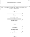
- FIG. 1 is a flowchart of a data receiving method according to an embodiment of the present disclosure. The method is applied to a terminal. As shown in FIG. 1 , the method includes the following steps.
- the terminal in this embodiment may be in an idle (IDLE) state or an inactive (INACTIVE) state.
- the paging message may be a specific paging message, and configuration information different from that for a paging message in a related technology is used.
- the downlink data may be data radio bearer (Data Radio Bearer, DRB) data.
- the indication information indicating that the downlink data of the terminal is sent may be identification information of the terminal, for example, I-RNTI or ng-5G-S-TMSI, or may be 1-bit indication information.
- the indication information is 1, it indicates that the downlink data of the terminal is sent.
- the paging message may be identified by identification information indicating that downlink data is sent.
- the identification information may be P-Data-RNTI, and a corresponding paging message is scheduled and sent by using scheduling information identified by the P-Data-RNTI.
- the terminal may further receive paging message configuration information from the network device and configuration information for receiving downlink data associated with the paging message configuration information.
- the UE receives system information SIB 8 of a cell 1, where the SIB 8 includes specific paging message configuration information (for example, pagingForDataConfig) and configuration information (for example, dataConfig) for receiving downlink data associated with the specific paging message configuration information.
- specific paging message configuration information is different from common paging message configuration information (for example, pagingConfig) that is not used for data sending in a related technology.
- the configuration information for receiving the downlink data includes at least one of the following:
- the terminal may further restore the configuration information used by the terminal to receive the downlink data.
- the configuration information used for receiving the downlink data may be a security algorithm, a security key, DRB configuration information, or the like.
- a paging message is received, and when the paging message includes indication information indicating that downlink data of a terminal is to be sent, the downlink data of the terminal is obtained, so that when the terminal is in an idle state or an inactive state, a network device directly sends corresponding downlink data to the terminal, thereby reducing a sending delay of the downlink data.
- the terminal may further send feedback information to the network device.
- the feedback information may include but is not limited to at least one of the following:
- a sending resource of the foregoing feedback information may be indicated by the network device, and an indication manner may include either of the following:
- the downlink data of the terminal may be sent at the same time as the paging message, or may be sent at a downlink data sending location associated with the paging message.
- the downlink data of the terminal and the paging message are separately sent.
- the downlink data of the terminal and the paging (paging) message may be sent simultaneously in a same media access control (Media Access Control, MAC) protocol data unit (Protocol Data Unit, PDU).
- the MAC PDU may be transmission content in a physical downlink shared channel (physical downlink shared channel, PDSCH), that is, the downlink data of the terminal and the paging message may be simultaneously in a same PDSCH.
- PDSCH physical downlink shared channel
- the terminal may further receive paging message configuration information from the network device and configuration information for receiving downlink data associated with the paging message configuration information.
- the UE receives system information SIB 8 of a cell 1, where the SIB 8 includes specific paging message configuration information (for example, pagingForDataConfig) and configuration information (for example, dataConfig) for receiving downlink data associated with the specific paging message configuration information.
- specific paging message configuration information is different from common paging message configuration information (for example, pagingConfig) that is not used for data sending in a related technology.
- the configuration information for receiving the downlink data includes at least one of the following:
- the terminal may receive the corresponding downlink data by using the paging message.
- the network device may further send configuration information to the terminal, where the configuration information is used to instruct the terminal to store the configuration information for receiving the downlink data in the INACTIVE or IDLE state.
- the configuration information for receiving the downlink data may include at least one of the following: a DRB identifier (for example, the downlink data of the UE is sent by using a DRB 1) for receiving the downlink data and indication information (for example, the downlink data of the UE is carried in a downlink radio resource control (Radio Resource Control, RRC) message) for receiving the downlink data by using control plane signaling.
- a DRB identifier for example, the downlink data of the UE is sent by using a DRB 1
- indication information for example, the downlink data of the UE is carried in a downlink radio resource control (Radio Resource Control, RRC) message) for receiving the downlink data by using control plane signaling.
- RRC Radio Resource Control
- a base station 1 may send an RRC release (RRC Release) message to the UE 1, to instruct the UE 1 to enter the INACTIVE state, and instruct the UE to store the configuration information used for receiving the downlink data.
- RRC release RRC Release
- the obtaining the downlink data of the terminal in step 102 may include:
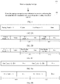
- the downlink data (data) of the terminal may be arranged after the paging message (Paging).
- the data format 1 may further additionally include the following content:
- the downlink data (data) of the multiple terminals may be arranged in a terminal sequence indicated in the paging message (Paging) (the terminal sequence may be a sequence identified by the terminal). For example, as shown in FIG. 2B , if the paging message indicates that a UE identifier indicating that data is sent includes UE 1 and UE 2, the paging message is followed by data of the UE 1, and the data of the UE 1 is followed by data of the UE 2.
- the data format 2 may further additionally include the following content:
- the data format 2 may further additionally include the following content:
- terminal identification information may be any one of the following: a truncated part of the terminal identification information, identification information obtained through calculation based on the terminal identifier, or logical channel identifier information corresponding to the terminal identifier (for example, a terminal identifier indicated by the first indication in the paging message corresponds to a logical channel identifier 1, or a terminal identifier indicated by the second indication in the paging message corresponds to a logical channel identifier 2).
- the terminal identification information directly indicates the terminal identifier.
- the UE may monitor sending of the paging message (that is, a specific paging message in this embodiment), for example, obtain scheduling information of the paging message by monitoring a PDCCH of the P-Data-RNTI. If the UE learns, through listening, that the PDCCH of the P-Data-RNTI schedules sending of the paging message, the UE may receive the paging message.
- sending of the paging message that is, a specific paging message in this embodiment
- the UE decodes downlink data corresponding to the UE.
- a UE identifier such as I-RNTI or ng-5G-S-TMSI
- indication information indicating that downlink data of the UE is received
- the downlink data of the terminal may be sent by using a downlink resource (for example, a physical downlink shared channel (Physical Downlink Shared Channel, PDSCH) channel) associated with the paging (paging) message).
- a downlink resource for example, a physical downlink shared channel (Physical Downlink Shared Channel, PDSCH) channel
- PDSCH Physical Downlink Shared Channel
- the terminal may further receive paging message configuration information from the network device and configuration information for receiving downlink data associated with the paging message configuration information.
- the UE receives system information SIB 8 of a cell 1, where the SIB 8 includes specific paging message configuration information (for example, pagingForDataConfig) and configuration information (for example, dataConfig) for receiving downlink data associated with the specific paging message configuration information.
- specific paging message configuration information is different from common paging message configuration information (for example, pagingConfig) that is not used for data sending in a related technology.
- the configuration information for receiving the downlink data includes at least one of the following:
- a resource location of paging message scheduling information may be a subframe 1 in a cycle of 10 ms, and a resource location of corresponding downlink data scheduling information may be a subframe 2 in the cycle of 10 ms.
- the terminal may receive the downlink data scheduling information, and receive the downlink data based on the received downlink data scheduling information.
- a resource location of paging message scheduling information may be one PO (Paging Occasion) in a cycle of 10 ms, and in the PO, S PDCCH monitoring locations correspond to S transmitted SSBs in one SSB burst, and a PDCCH monitoring locations of the K th paging in the S PDCCH monitoring locations in the PO corresponds to the K th transmitted SSB.
- the S transmitted SSBs in the one SSB burst correspond to S sending scheduling information sending locations for S pieces of downlink data, and a PDCCH monitoring location of the K th downlink data corresponds to the K th transmitted SSB.
- three PDCCH monitoring locations correspond to three SSBs, and the three SSBs correspond to PDCCH monitoring locations of three pieces of downlink data.
- the UE 1 may receive the paging message at a location of a PDCCH (paging)-1, and receive the downlink data at the location of the PDCCH (data)-1.
- identification information for sending the downlink data may be an identifier of PDCCH scheduling information of the downlink data, for example, Data-RNTI.
- the PDCCH scheduling information of the downlink data may have multiple identifiers, for example, multiple Data-RNTIs.
- different UEs may correspond to identification information for sending different downlink data.
- identification information for sending multiple pieces of downlink data is sequentially allocated in an arrangement sequence of the multiple UEs that are indicated in the paging message and that send downlink data.
- an arrangement sequence of the identification information for sending the downlink data indicated in a system message is: Data-RNTI-1; Data-RNTI-2.
- Identification information of UEs that are indicated in the paging message and that send data is arranged in the following sequence: UE-ID-1; UE-ID-2.
- identification information for sending downlink data corresponding to UE-ID-1 is Data-RNTI-1
- identification information for sending downlink data corresponding to UE-ID-2 is Data-RNTI-2.
- the network device may further send configuration information to the terminal, where the configuration information is used to instruct the terminal to store the configuration information for receiving the downlink data in the INACTIVE or IDLE state.
- the configuration information for receiving the downlink data may include at least one of the following: a DRB identifier (for example, the downlink data of the UE is sent by using a DRB 1) for receiving the downlink data and indication information (for example, the downlink data of the UE is carried in a downlink RRC message) for receiving the downlink data by using control plane signaling.
- a base station 1 may send an RRC release (RRC Release) message to the UE 1, to instruct the UE 1 to enter the INACTIVE state, and instruct the UE to store the configuration information used for receiving the downlink data.
- RRC release RRC Release
- the obtaining the downlink data of the terminal in step 102 may include: receiving the downlink data of the terminal at a downlink data receiving location associated with the paging message.
- a downlink data sending location and a downlink data receiving location are a same location, and different statements are used for different relative bodies. It is a downlink data sending location for the network device, and is a downlink data receiving location for the terminal.
- the receiving the downlink data of the terminal may include: receiving, by using either of the following information, the downlink data of the terminal at the downlink data receiving location associated with the paging message: identification information for distinguishing downlink data of different terminals; where for example, if scheduling information of downlink data of both UE-1 and UE-2 is sent in a slot-1, Data-RNTI-1 is used to send downlink data scheduling information of the UE-1, and Data-RNTI-2 is used to send downlink data scheduling information of the UE-2.
- different UE data is distinguished by using different identifiers; and a preset data packet format for distinguishing downlink data of different terminals.
- the preset data packet format may be either of the following:
- a data header (for example, Data Header) corresponding to data (data) of each terminal, where the data header may be referred to as a data packet header, and the data header may include indication information indicating a length of the corresponding terminal data (for example, a length L of the terminal data indicated by the indication information may be equal to 10 bytes) and terminal identifier indication information, as shown in an ID 1 and an ID 2 in FIG. 3A .
- the ID1 is, for example, a logical channel 1, and corresponds to a UE-ID-1 in the paging message.
- the ID 2 is, for example, a logical channel 2, and corresponds to a UE-ID-2 in the paging message.
- the terminal identification information may be an implicit indication or an explicit indication.
- the terminal identification information may be any one of the following: a truncated part of terminal identification information, identification information obtained through calculation based on the terminal identification information, a numbering sequence for identifiers of terminals that are indicated in the paging message and that send data (for example, an identifier of the first terminal that is indicated in the paging message and that sends data is a value 1, an identifier of the second terminal that is indicated in the paging message and that sends data is a value 2), and logical channel identifier information corresponding to the terminal identifier (for example, the first terminal identifier indicated in the paging message corresponds to a logical channel identifier 1, and the second terminal identifier indicated in the paging message corresponds to a logical channel identifier 2), and the like.
- the terminal identification information directly indicates the terminal identifier.
- data (data) of each terminal has a corresponding data header (for example, Data Header), and the data header may include indication information indicating a length of the corresponding terminal data.
- a length L of terminal data indicated by the indication information may be equal to 10 bytes.
- the method may further include: sending uplink indication information to the network device.
- the uplink indication information may indicate a location of the terminal, so that the network device sends the downlink data to the terminal based on the location of the terminal.
- the uplink indication information may indicate a cell in which the terminal sends the uplink indication information. In this way, when sending the downlink data to the terminal, the network device may send the corresponding downlink data to the terminal by using the cell indicated by the uplink indication information.
- the uplink indication information may notify the network device that the paging message is received, so that the network device sends the downlink data to the terminal by using a location (for example, a cell) at which the terminal sends the uplink indication information.
- a sending resource location of the uplink indication information may be associated with the paging (paging) message.
- the resource location of the uplink indication information may be a subframe 2 in the cycle of 10 ms. In this way, in the subframe 2, the terminal may send corresponding uplink indication information.
- a resource location of the paging message scheduling information may be one PO (Paging Occasion) in a cycle of 10 ms, and in the PO, S PDCCH monitoring locations correspond to S transmitted SSBs in one SSB burst, and a PDCCH monitoring locations of the K th paging in the S PDCCH monitoring locations in the PO corresponds to the K th transmitted SSB.
- the S transmitted SSBs in the one SSB burst correspond to S sending scheduling information sending locations
- the K th piece of uplink indication information sending location corresponds to the K th transmitted SSB.
- three PDCCH monitoring locations correspond to three SSBs, and the three SSBs correspond to three uplink indication information sending locations.
- the UE 1 may receive the paging message at a location of a PDCCH (paging)-1, and send the uplink indication information at a location of PRACH (data)-1.
- a channel corresponding to the uplink indication information may be any one of the following:
- the foregoing uplink indication information may include identification information of the terminal, so that the network device distinguishes different terminals.
- the PUSCH includes an I-RNTI identifier of the terminal.
- an uplink PRACH resource corresponding to the first terminal identifier that is indicated in the paging message to have downlink data transmission is PRACH-1 (in other words, a terminal identifier is associated with a sending resource of the uplink indication information, to implicitly indicate the terminal identifier).
- FIG. 4 is a flowchart of a data sending method according to an embodiment of the present disclosure. The method is applied to a network device. As shown in FIG. 4 , the method includes the following steps.
- Step 401 Send a paging message to a terminal.
- Step 402 When the paging message includes indication information indicating that downlink data of a terminal is to be sent, send the downlink data of the terminal.
- the terminal in this embodiment may be in an idle (IDLE) state or an inactive (INACTIVE) state.
- the paging message may be a specific paging message, and configuration information different from that for a paging message in a related technology is used.
- the downlink data may be data radio bearer (Data Radio Bearer, DRB) data.
- the indication information indicating that the downlink data of the terminal is sent may be identification information of the terminal, for example, I-RNTI or ng-5G-S-TMSI, or may be 1-bit indication information.
- the indication information is 1, it indicates that the downlink data of the terminal is sent.
- the network device when the terminal is in an idle state or an inactive state, the network device directly sends the corresponding downlink data to the terminal, thereby reducing a sending delay of the downlink data.
- the sending the downlink data of the terminal in step 402 may include: send the downlink data of the terminal based on a preset data format in a MAC PDU that sends the paging message.
- the preset data format may be either of the following:
- the method may further include:
- the sending the downlink data of the terminal in step 402 may include: send the downlink data of the terminal at a downlink data sending location associated with the paging message.
- the method may further include:
- the method may further include: receiving uplink indication information from the terminal.
- step 402 may include: send, based on the uplink indication information, the downlink data of the terminal at the downlink data sending location associated with the paging message.
- the uplink indication information may indicate a location of the terminal, so that the network device sends the downlink data to the terminal based on the location of the terminal.
- the uplink indication information may indicate a cell in which the terminal sends the uplink indication information. In this way, when sending the downlink data to the terminal, the network device may send the corresponding downlink data to the terminal by using the cell indicated by the uplink indication information.
- the uplink indication information may notify the network device that the paging message is received, so that the network device sends the downlink data to the terminal by using a location (for example, a cell) at which the terminal sends the uplink indication information.
- a sending resource location of the uplink indication information is associated with the paging message.
- the uplink indication information includes identification information of the terminal.
- step 402 may include: sending, by using any one of the following information, the downlink data of the terminal at the downlink data sending location associated with the paging message:
- the preset data packet format is either of the following:
- the method further includes:
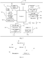
- FIG. 5 is a schematic structural diagram of a terminal according to an embodiment of the present disclosure. As shown in FIG. 5 , a terminal 50 includes:
- a paging message is received, and when the paging message includes indication information indicating that downlink data of a terminal is to be sent, the downlink data of the terminal is obtained, so that when the terminal is in an idle state or an inactive state, a network device directly sends corresponding downlink data to the terminal, thereby reducing a sending delay of the downlink data.
- the obtaining module 52 is further configured to: obtain, through decoding based on a preset data format, the downlink data of the terminal from a MAC PDU that sends the paging message.
- the preset data format may be either of the following:
- the terminal 50 may further include:
- the obtaining module 52 may further include: a receiving unit, configured to receive the downlink data of the terminal at a downlink data receiving location associated with the paging message.
- the terminal 50 may further include:
- the terminal 50 may further include: a first sending module, configured to send indication information to the network device.
- a first sending module configured to send indication information to the network device.
- a sending resource location of the uplink indication information is associated with the paging message.
- the uplink indication information includes identification information of the terminal.
- a channel corresponding to the uplink indication information may be any one of the following: PRACH, PUSCH, PUCCH, and SRS.
- the obtaining module 52 is further configured to: when downlink data of multiple terminals is received at a downlink data receiving location associated with the paging message, receive, by using either of the following information, the downlink data of the terminal at a downlink data receiving location associated with the paging message:
- the preset data packet format is either of the following:
- the terminal 50 may further include: a processing module, configured to restore configuration information that is used by the terminal to receive the downlink data.
- a processing module configured to restore configuration information that is used by the terminal to receive the downlink data.
- the terminal 50 may further include:
- a sending resource indication manner of the feedback information includes either of the following:
- the paging message is identified by identification information indicating that downlink data is sent.
- FIG. 6 is a schematic structural diagram of a network device according to an embodiment of the present disclosure. As shown in FIG. 6 , a network device 60 includes:
- the network device when the terminal is in an idle state or an inactive state, the network device directly sends the corresponding downlink data to the terminal, thereby reducing a sending delay of the downlink data.
- the fourth sending module 62 is configured to: send the downlink data of the terminal based on a preset data format in a MAC PDU that sends the paging message.
- the preset data format may be either of the following:
- the network device 60 may further include:
- the fourth sending module 62 is configured to: send the downlink data of the terminal at a downlink data sending location associated with the paging message.
- the network device 60 may further include:
- the network device 60 may further include: a fourth receiving module, configured to receive uplink indication information from the terminal.
- the fourth sending module 62 is configured to: send, based on the uplink indication information, the downlink data of the terminal at the downlink data sending location associated with the paging message.
- a sending resource location of the uplink indication information is associated with the paging message.
- the uplink indication information includes identification information of the terminal.
- the fourth sending module 62 is configured to: when downlink data of multiple terminals is received at a downlink data sending location associated with the paging message, send, by using either of the following information, the downlink data of the terminal at the downlink data receiving location associated with the paging message:
- the preset data packet format is either of the following:
- the network device 60 may further include:
- An embodiment of the present disclosure further provides a communication device, including a processor, a memory, and a computer program that is stored in the memory and that runs on the processor.
- a communication device including a processor, a memory, and a computer program that is stored in the memory and that runs on the processor.
- the computer program is executed by the processor, processes of the data receiving method embodiment shown in FIG. 1 can be implemented, or processes of the data sending method embodiment shown in FIG. 4 can be implemented, and a same technical effect can be achieved. To avoid repetition, details are not described herein again.
- the communication device may optionally be a terminal or a network device.
- FIG. 7 is a schematic diagram of a hardware structure of a terminal for implementing embodiments of the present disclosure.
- the terminal 700 includes but is not limited to components such as a radio frequency unit 702, a network module 701, an audio output unit 703, an input unit 704, a sensor 705, a display unit 706, a user input unit 707, an interface unit 708, a memory 709, a processor 710, and a power supply 711.
- a structure of the terminal shown in FIG. 7 does not constitute a limitation on the terminal, and the terminal may include more or fewer components than those shown in the figure, or combine some components, or have different component arrangements.
- the terminal includes but is not limited to a mobile phone, a tablet computer, a laptop computer, a palmtop computer, an in-vehicle terminal, a wearable device, a pedometer, and the like.
- the radio frequency unit 701 is configured to receive a paging message.
- the processor 710 is configured to: when the paging message includes indication information indicating that downlink data of the terminal is to be sent, obtain the downlink data of the terminal.
- terminal 700 in this embodiment of the present disclosure may implement processes implemented in the foregoing method embodiment shown in FIG. 1 and achieve a same beneficial effect. To avoid repetition, details are not described herein again.
- the radio frequency unit 701 may be configured to receive and send information or receive and send a signal in a call process. Specifically, after downlink data from a base station is received, the processor 710 processes the downlink data. In addition, uplink data is sent to the base station.
- the radio frequency unit 701 includes but is not limited to an antenna, at least one amplifier, a transceiver, a coupler, a low noise amplifier, a duplexer, and the like.
- the radio frequency unit 701 may further communicate with a network and another device by using a wireless communication system.
- the terminal provides wireless broadband Internet access for a user by using a network module 702, for example, helping the user send and receive an email, browsing a web page, and accessing streaming media.
- the audio output unit 703 may convert audio data received by the radio frequency unit 701 or the network module 702 or stored in the memory 709 into an audio signal and output as sound. In addition, the audio output unit 703 may further provide audio output (for example, call signal receiving sound or message receiving sound) related to a specific function performed by the terminal 700.
- the audio output unit 703 includes a loudspeaker, a buzzer, a telephone receiver, and the like.
- the input unit 704 is configured to receive an audio or video signal.
- the input unit 704 may include a graphics processing unit (Graphics Processing Unit, GPU) 7041 and a microphone 7042.
- the graphics processing unit 7041 processes image data of a static picture or a video obtained by an image capture apparatus (such as a camera) in a video capture mode or an image capture mode.
- a processed image frame may be displayed on the display unit 706.
- the image frame processed by the graphics processing unit 7041 may be stored in the memory 709 (or another storage medium) or sent by using the radio frequency unit 701 or the network module 702.
- the microphone 7042 may receive sound and can process such sound into audio data.
- the processed audio data may be output by being converted into a format that may be sent to a mobile communications base station by using the radio frequency unit 701 in a telephone call mode.
- the terminal 700 further includes at least one sensor 705, such as an optical sensor, a motion sensor, and another sensor.
- the optical sensor includes an ambient light sensor and a proximity sensor.
- the ambient light sensor may adjust luminance of the display panel 7061 based on brightness of ambient light
- the proximity sensor may disable the display panel 7061 and/or backlight when the terminal 700 approaches an ear.
- an accelerometer sensor may detect magnitude of an acceleration in each direction (generally three axes), and may detect magnitude and a direction of gravity when being static.
- the accelerometer sensor may be used for recognizing a terminal gesture (for example, horizontal and vertical screen switching, a related game, or magnetometer posture calibration), a function related to vibration recognition (for example, a pedometer or a strike), or the like.
- the sensor 705 may further include a fingerprint sensor, a pressure sensor, an iris sensor, a molecular sensor, a gyroscope, a barometer, a hygrometer, a thermometer, an infrared sensor, and the like. This is not described herein.
- the display unit 706 is configured to display information entered by the user or information provided for the user.
- the display unit 706 may include a display panel 7061, and the display panel 7061 may be configured in a form of a liquid crystal display (Liquid Crystal Display, LCD), an organic light-emitting diode (Organic Light-Emitting Diode, OLED), or the like.
- LCD Liquid Crystal Display
- OLED Organic Light-Emitting Diode
- the user input unit 707 may be configured to receive input digit or character information and generate key signal input related to user setting and function control of a terminal.
- the user input unit 707 includes a touch panel 7071 and another input device 7072.
- the touch panel 7071 also referred to as a touchscreen, may collect a touch operation performed by the user on or near the touch panel 7071 (for example, an operation performed by the user on or near the touch panel 7071 by using any suitable object or accessory such as a finger or a stylus).
- the touch panel 7071 may include two parts: a touch detection apparatus and a touch controller.
- the touch detection apparatus detects a touch position of the user, detects a signal brought by the touch operation, and transmits the signal to the touch controller.
- the touch controller receives touch information from the touch detection apparatus, converts the touch information into contact coordinates, sends the contact coordinates to the processor 710, and can receive and execute a command sent by the processor 710.
- the touch panel 7071 may be implemented by using a plurality of types such as a resistive type, a capacitive type, an infrared ray, and a surface acoustic wave.
- the user input unit 707 may include another input device 7072 in addition to the touch panel 7071.
- the another input device 7072 may include but is not limited to one or more of a physical keyboard, a function key (such as a volume control key or an on/off key), a trackball, a mouse, a joystick, and the like. Details are not described herein.
- the touch panel 7071 may cover the display panel 7061. After detecting the touch operation on or near the touch panel 7071, the touch panel 7061 transmits the touch operation to the processor 710 to determine a type of a touch event, and then the processor 710 provides corresponding visual output on the display panel 7061 based on the type of the touch event.
- the touch panel 7071 and the display panel 7061 are used as two independent components to implement input and output functions of the terminal. However, in some embodiments, the touch panel 7071 and the display panel 7061 may be integrated to implement the input and output functions of the terminal. This is not specifically limited herein.
- the interface unit 708 is an interface connecting an external apparatus to the terminal 700.
- the external apparatus may include a wired or wireless headset port, an external power supply (or battery charger) port, a wired or wireless data port, a storage card port, a port configured to connect to an apparatus having an identification module, an audio input/output (input/output, I/O) port, a video I/O port, a headset port, and the like.
- the interface unit 708 may be configured to receive input (for example, data information and power) from the external apparatus and transmit the received input to one or more elements in the terminal 700, or may be configured to transmit data between the terminal 700 and the external apparatus.
- the memory 709 may be configured to store a software program and various data.
- the memory 709 may mainly include a program storage area and a data storage area.
- the program storage area may store an operating system, an application program required by at least one function (such as a sound play function or an image play function), and the like.
- the data storage area may store data (such as audio data or an address book) or the like created based on use of the mobile phone.
- the memory 709 may include a high-speed random access memory, and may further include a non-volatile memory such as at least one magnetic disk storage component, a flash memory component, or another volatile solid-state storage component.
- the processor 710 is a control center of the terminal, and is connected to all parts of the entire terminal by using various interfaces and lines, and performs various functions of the terminal and processes data by running or executing the software program and/or the module that are stored in the memory 709 and invoking the data stored in the memory 709, to implement overall monitoring on the terminal.
- the processor 710 may include one or more processing units.
- the processor 710 may be integrated with an application processor and a modem processor.
- the application processor mainly processes an operating system, a user interface, an application program, and the like, and the modem processor mainly processes wireless communication. It may be understood that the modem processor may alternatively not be integrated into the processor 710.
- the terminal 700 may further include a power supply 711 (such as a battery) that supplies power to each component.
- a power supply 711 (such as a battery) that supplies power to each component.
- the power supply 711 may be logically connected to the processor 710 by using a power management system, to implement functions such as charging, discharging, and power consumption management by using the power management system.
- terminal 700 may further include some function modules not shown, and details are not described herein.
- FIG 8 is a schematic diagram of a hardware structure of a network device for implementing embodiments of the present disclosure.
- the network device 80 includes but is not limited to a bus 81, a transceiver 82, an antenna 83, a bus interface 84, a processor 85, and a memory 86.
- the network side device 80 further includes a computer program that is stored in the memory 86 and that can run on the processor 85.
- the computer program is executed by the processor 85, the following steps are implemented: sending a paging message to a terminal; and when the paging message includes indication information indicating that downlink data of the terminal is to be sent, sending the downlink data of the terminal.
- the transceiver 82 is configured to receive and send data under the control of the processor 85.
- the network device 80 in this embodiment of the present disclosure may implement processes implemented in the foregoing method embodiment shown in FIG. 4 and achieve a same beneficial effect. To avoid repetition, details are not described herein again.
- the bus 81 may include any quantity of interconnected buses and bridges, and the bus 81 links various circuits including one or more processors represented by the processor 85 and a memory represented by the memory 86.
- the bus 81 may further link various other circuits such as a peripheral device, a voltage regulator, and a power management circuit together. These are all well-known in the art, and therefore are not further described in the present specification.
- the bus interface 84 provides an interface between the bus 81 and the transceiver 82.
- the transceiver 82 may be one element or multiple elements, for example, multiple receivers and multiple transmitters, to provide a unit configured to communicate with various other apparatuses on a transmission medium.
- Data processed by the processor 85 is transmitted on a wireless medium by using the antenna 83. Further, the antenna 83 further receives data and transmits the data to the processor 85.
- the processor 85 is responsible for managing the bus 81 and common processing, and may further provide various functions, including timing, a peripheral interface, voltage regulation, power management, and other control functions.
- the memory 86 may be configured to store data used when the processor 85 performs an operation.
- the processor 85 may be a central processing unit (central processing unit, CPU), an ASIC, an FPGA, or a complex programmable logic device (Complex Programmable Logic Device, CPLD).
- CPU central processing unit
- ASIC application specific integrated circuit
- FPGA field-programmable gate array
- CPLD complex programmable logic device
- An embodiment of the present disclosure further provides a computer-readable storage medium.
- a computer program is stored in the computer-readable storage medium.
- the computer-readable storage medium includes a read-only memory (Read-Only Memory, ROM), a random access memory (Random Access Memory, RAM), a magnetic disk, an optical disc, or the like.
- the foregoing method embodiments may be implemented by using software and a required universal hardware platform, or certainly may be implemented by using hardware. However, in many cases, the former is a better implementation.
- the technical solutions of the present disclosure essentially or the part contributing to related technologies may be implemented in a form of a software product.
- the computer software product is stored in a storage medium (such as a ROM/RAM, a magnetic disk, or an optical disc) and includes several instructions for instructing a terminal (which may be a mobile phone, a computer, a server, an air conditioner, or a network device) to execute the methods described in the embodiments of the present disclosure.
- the disclosed apparatus and method may be implemented in another manner.
- the described apparatus embodiment is merely an example.
- the unit division is merely logical function division.
- multiple units or components may be combined or integrated into another system, or some features may be ignored or not performed.
- the displayed or discussed mutual coupling or direct coupling or communication connection may be through some interfaces, indirect coupling or communication connection of the apparatus or unit, and may be in an electrical, mechanical, or another form.
- the units described as separate parts may or may not be physically separate, and parts displayed as units may or may not be physical units, may be located in one place, or may be distributed on multiple network units. Some or all of the units may be selected based on an actual requirement to implement the objectives of the solutions in the embodiments.
- functional units in the embodiments of the present disclosure may be integrated into one processing unit, or each unit may exist separately physically, or two or more units may be integrated into one unit.
- the function may be stored in a computer readable storage medium if it is implemented in the form of a software functional unit and sold or used as an independent product. Based on such an understanding, the technical solutions of the present disclosure essentially or the part contributing to related technologies may be implemented in a form of a software product.
- the computer software product is stored in a storage medium and includes several instructions for instructing a computer device (which may be a personal computer, a server, a network device, or the like) to perform all or some steps in the method described in the embodiments of the present disclosure.
- the foregoing storage medium includes any medium that can store program code, such as a USB flash drive, a removable hard disk, a ROM, a RAM, a magnetic disk, or an optical disc.
- the program may be stored in a computer readable storage medium.
- the storage medium includes a magnetic disk, a compact disc, a read-only memory (Read-Only Memory, ROM), a random access memory (Random Access Memory, RAM), or the like.
- a module, a unit, a subunit, or the like may be implemented in one or more application specific integrated circuits (Application Specific Integrated Circuits, ASIC), a digital signal processor (Digital Signal Processing, DSP), a digital signal processing device (DSP Device, DSPD), a programmable logic device (Programmable Logic Device, PLD), a field-programmable gate array (Field-Programmable Gate Array, FPGA), a general purpose processor, a controller, a microcontroller, a microprocessor, another electronic unit configured to perform the functions described in the present disclosure, or a combination thereof.
- ASIC Application Specific Integrated Circuits
- DSP Digital Signal Processing
- DSP Device digital signal processing device
- PLD programmable logic device
- FPGA field-programmable gate array
- a general purpose processor a controller, a microcontroller, a microprocessor, another electronic unit configured to perform the functions described in the present disclosure, or a combination thereof.
- the techniques described in the embodiments of the present disclosure may be implemented by modules (for example, processes and functions) that perform the functions described in the embodiments of the present disclosure.
- the software code may be stored in a memory and executed by a processor.
- the memory may be implemented in or outside the processor.
Landscapes
- Engineering & Computer Science (AREA)
- Computer Networks & Wireless Communication (AREA)
- Signal Processing (AREA)
- Mobile Radio Communication Systems (AREA)
Applications Claiming Priority (2)
| Application Number | Priority Date | Filing Date | Title |
|---|---|---|---|
| CN201910741802.0A CN111836361B (zh) | 2019-08-12 | 2019-08-12 | 数据接收方法、发送方法、终端及网络设备 |
| PCT/CN2020/107392 WO2021027680A1 (zh) | 2019-08-12 | 2020-08-06 | 数据接收方法、发送方法、终端及网络设备 |
Publications (3)
| Publication Number | Publication Date |
|---|---|
| EP4017154A1 true EP4017154A1 (de) | 2022-06-22 |
| EP4017154A4 EP4017154A4 (de) | 2022-10-19 |
| EP4017154B1 EP4017154B1 (de) | 2025-04-09 |
Family
ID=72911992
Family Applications (1)
| Application Number | Title | Priority Date | Filing Date |
|---|---|---|---|
| EP20852647.5A Active EP4017154B1 (de) | 2019-08-12 | 2020-08-06 | Datenempfangsverfahren, übertragungsverfahren, endgerät und netzwerkvorrichtung |
Country Status (6)
| Country | Link |
|---|---|
| US (1) | US12185277B2 (de) |
| EP (1) | EP4017154B1 (de) |
| KR (1) | KR102879144B1 (de) |
| CN (1) | CN111836361B (de) |
| ES (1) | ES3029359T3 (de) |
| WO (1) | WO2021027680A1 (de) |
Families Citing this family (8)
| Publication number | Priority date | Publication date | Assignee | Title |
|---|---|---|---|---|
| CN113115485B (zh) * | 2020-01-10 | 2022-07-05 | 上海朗帛通信技术有限公司 | 用于不连续接收的方法和装置 |
| CN113891345B (zh) * | 2020-07-03 | 2024-04-19 | 大唐移动通信设备有限公司 | 数据传输方法、指示方法及设备 |
| WO2022027259A1 (zh) * | 2020-08-04 | 2022-02-10 | 北京小米移动软件有限公司 | 资源位置的确定方法、装置、通信设备和介质 |
| CN114666022B (zh) * | 2020-12-23 | 2024-11-22 | 维沃移动通信有限公司 | 非连接态定位方法、装置及设备 |
| CN114867107B (zh) * | 2021-02-03 | 2025-11-21 | 维沃移动通信有限公司 | 寻呼指示方法、装置、网络侧设备及终端 |
| CN114189934B (zh) * | 2021-12-07 | 2024-04-26 | 中国建设银行股份有限公司 | 一种重复寻呼确定方法、装置、设备及介质 |
| CN118042649A (zh) * | 2022-11-04 | 2024-05-14 | 维沃移动通信有限公司 | 数据接收、信息传输方法、装置、终端及网络侧设备 |
| CN119342582A (zh) * | 2023-07-21 | 2025-01-21 | 维沃移动通信有限公司 | 寻呼方法、装置、设备及可读存储介质 |
Family Cites Families (20)
| Publication number | Priority date | Publication date | Assignee | Title |
|---|---|---|---|---|
| CN101674649B (zh) * | 2008-09-11 | 2012-10-03 | 电信科学技术研究院 | 寻呼状态下数据传输的方法、系统及装置 |
| TWI539792B (zh) * | 2013-10-22 | 2016-06-21 | 宏碁股份有限公司 | 微量資料傳輸方法及使用者設備 |
| EP3244643B1 (de) * | 2015-01-28 | 2020-02-26 | Huawei Technologies Co., Ltd. | Endgerätevorrichtung, netzwerkvorrichtung und gruppenkommunikationsverfahren |
| CN107370573B (zh) * | 2016-05-12 | 2022-10-11 | 大唐移动通信设备有限公司 | 一种下行数据传输的方法及设备 |
| CN107666708B (zh) * | 2016-07-27 | 2019-12-20 | 电信科学技术研究院 | 一种下行数据传输方法及装置 |
| CN106792792B (zh) * | 2016-09-30 | 2019-01-29 | 展讯通信(上海)有限公司 | 基站、用户终端及其下行数据控制方法及装置 |
| TWI752992B (zh) * | 2016-09-30 | 2022-01-21 | 日商索尼股份有限公司 | 通訊裝置、基礎結構設備、通訊系統及方法 |
| CN107889216B (zh) * | 2016-09-30 | 2022-04-29 | 中兴通讯股份有限公司 | 数据发送、接收方法及装置、基站、终端 |
| CN109923915B (zh) | 2016-11-13 | 2021-11-16 | Lg电子株式会社 | 用于接收下行链路信号的方法和用户设备 |
| CN108616901B (zh) * | 2016-12-12 | 2020-09-01 | 维沃移动通信有限公司 | 一种呼叫终端的方法、终端及网络设备 |
| US10721763B2 (en) | 2017-01-20 | 2020-07-21 | Qualcomm Incorporated | Small packet optimizations for internet-of-things applications |
| CN108696340B (zh) * | 2017-04-05 | 2022-09-27 | 中兴通讯股份有限公司 | 反馈信息的发送、接收方法及装置 |
| US10660065B2 (en) * | 2017-04-13 | 2020-05-19 | Lg Electronics Inc. | Method for transmitting a paging message and device supporting the same |
| CN108738139B (zh) * | 2017-04-18 | 2022-01-11 | 华为技术有限公司 | 下行数据传输方法及装置 |
| CN110832942B (zh) * | 2017-07-07 | 2021-09-03 | 华为技术有限公司 | 随机接入的方法、终端设备和网络设备 |
| CN109600831B (zh) | 2017-09-30 | 2021-10-22 | 维沃移动通信有限公司 | 一种寻呼方法、终端及网络侧设备 |
| CN108235412B (zh) | 2017-12-19 | 2021-09-10 | 中兴通讯股份有限公司 | 一种电能优化的方法、装置、系统及用户设备 |
| WO2020085964A1 (en) * | 2018-10-26 | 2020-04-30 | Telefonaktiebolaget Lm Ericsson (Publ) | Solutions for enabling low overhead data transmission for cellular devices |
| EP3928569B1 (de) * | 2019-02-22 | 2024-09-11 | Sony Group Corporation | Kommunikationsvorrichtung, infrastrukturausrüstung und verfahren |
| KR20200110201A (ko) * | 2019-03-14 | 2020-09-23 | 한국전자통신연구원 | 통신 시스템에서 단말의 접속 제어 방법 |
-
2019
- 2019-08-12 CN CN201910741802.0A patent/CN111836361B/zh active Active
-
2020
- 2020-08-06 ES ES20852647T patent/ES3029359T3/es active Active
- 2020-08-06 EP EP20852647.5A patent/EP4017154B1/de active Active
- 2020-08-06 KR KR1020227007296A patent/KR102879144B1/ko active Active
- 2020-08-06 WO PCT/CN2020/107392 patent/WO2021027680A1/zh not_active Ceased
-
2022
- 2022-02-11 US US17/669,501 patent/US12185277B2/en active Active
Also Published As
| Publication number | Publication date |
|---|---|
| EP4017154B1 (de) | 2025-04-09 |
| CN111836361A (zh) | 2020-10-27 |
| WO2021027680A1 (zh) | 2021-02-18 |
| ES3029359T3 (en) | 2025-06-24 |
| KR20220045185A (ko) | 2022-04-12 |
| US12185277B2 (en) | 2024-12-31 |
| US20220167306A1 (en) | 2022-05-26 |
| CN111836361B (zh) | 2022-06-17 |
| KR102879144B1 (ko) | 2025-11-03 |
| EP4017154A4 (de) | 2022-10-19 |
Similar Documents
| Publication | Publication Date | Title |
|---|---|---|
| US12185277B2 (en) | Data receiving method, data sending method, terminal, and network device | |
| CN110351813B (zh) | 一种信息上报方法、终端及网络设备 | |
| US12309870B2 (en) | Wake up signal processing method, wake up signal configuration method, and related device | |
| US12069608B2 (en) | Paging indication method, apparatus, and system | |
| US20210251039A1 (en) | Sidelink release method, terminal and network side device | |
| CN110719628B (zh) | 传输方法、终端设备及网络设备 | |
| EP4054284A1 (de) | Wecksignal-konfigurationsverfahren, wecksignal-verarbeitungsverfahren und zugehörige vorrichtung | |
| EP4057683A1 (de) | Zellenüberlastungsverarbeitungsverfahren, endgerät und netzseitige vorrichtung | |
| US20210337618A1 (en) | Connection Establishment Method, Terminal Device, and Network Device | |
| EP4142387A1 (de) | Funkrufantwortverfahren, endgerät und netzwerkvorrichtung | |
| EP3876591A1 (de) | Sidelink-verbindungssteuerungsverfahren, endgerät und netzwerkseitige vorrichtung | |
| EP4054280A1 (de) | Verfahren und vorrichtung zur verarbeitung von funkverbindungsfehlern | |
| CN110719647B (zh) | 一种随机接入方法、终端及网络设备 | |
| KR102755867B1 (ko) | Pucch의 송신 방법, 수신 방법, 단말 및 네트워크 측 장치 | |
| CN111836311B (zh) | 能力协商方法、终端及网络设备 | |
| WO2020200117A1 (zh) | 随机接入方法、指示方法、网络设备及终端 | |
| EP4037369A1 (de) | Referenzsignalübertragungsverfahren und -vorrichtung | |
| US12144051B2 (en) | Information sending method, information receiving method, terminal, and network device | |
| EP4057690A1 (de) | Übergabeverfahren, konfigurationsverfahren, endgerät und netzwerkvorrichtung | |
| CN110011752B (zh) | 一种cqi上报方法、终端设备及网络设备 | |
| CN111435861B (zh) | 一种信息发送方法及终端 | |
| HK40072715A (en) | Handover method, configuration method, terminal, and network device | |
| CN110708143A (zh) | 上行传输的反馈方法、网络设备及终端 |
Legal Events
| Date | Code | Title | Description |
|---|---|---|---|
| STAA | Information on the status of an ep patent application or granted ep patent |
Free format text: STATUS: THE INTERNATIONAL PUBLICATION HAS BEEN MADE |
|
| PUAI | Public reference made under article 153(3) epc to a published international application that has entered the european phase |
Free format text: ORIGINAL CODE: 0009012 |
|
| STAA | Information on the status of an ep patent application or granted ep patent |
Free format text: STATUS: REQUEST FOR EXAMINATION WAS MADE |
|
| 17P | Request for examination filed |
Effective date: 20220310 |
|
| AK | Designated contracting states |
Kind code of ref document: A1 Designated state(s): AL AT BE BG CH CY CZ DE DK EE ES FI FR GB GR HR HU IE IS IT LI LT LU LV MC MK MT NL NO PL PT RO RS SE SI SK SM TR |
|
| A4 | Supplementary search report drawn up and despatched |
Effective date: 20220920 |
|
| RIC1 | Information provided on ipc code assigned before grant |
Ipc: H04W 76/27 20180101ALN20220914BHEP Ipc: H04W 74/04 20090101ALI20220914BHEP Ipc: H04W 72/12 20090101ALI20220914BHEP Ipc: H04W 68/00 20090101AFI20220914BHEP |
|
| DAV | Request for validation of the european patent (deleted) | ||
| DAX | Request for extension of the european patent (deleted) | ||
| GRAP | Despatch of communication of intention to grant a patent |
Free format text: ORIGINAL CODE: EPIDOSNIGR1 |
|
| STAA | Information on the status of an ep patent application or granted ep patent |
Free format text: STATUS: GRANT OF PATENT IS INTENDED |
|
| RIC1 | Information provided on ipc code assigned before grant |
Ipc: H04W 80/02 20090101ALN20241121BHEP Ipc: H04W 76/27 20180101ALN20241121BHEP Ipc: H04W 4/20 20180101ALI20241121BHEP Ipc: H04W 68/00 20090101AFI20241121BHEP |
|
| INTG | Intention to grant announced |
Effective date: 20241128 |
|
| GRAS | Grant fee paid |
Free format text: ORIGINAL CODE: EPIDOSNIGR3 |
|
| GRAA | (expected) grant |
Free format text: ORIGINAL CODE: 0009210 |
|
| STAA | Information on the status of an ep patent application or granted ep patent |
Free format text: STATUS: THE PATENT HAS BEEN GRANTED |
|
| AK | Designated contracting states |
Kind code of ref document: B1 Designated state(s): AL AT BE BG CH CY CZ DE DK EE ES FI FR GB GR HR HU IE IS IT LI LT LU LV MC MK MT NL NO PL PT RO RS SE SI SK SM TR |
|
| REG | Reference to a national code |
Ref country code: GB Ref legal event code: FG4D |
|
| REG | Reference to a national code |
Ref country code: CH Ref legal event code: EP |
|
| REG | Reference to a national code |
Ref country code: DE Ref legal event code: R096 Ref document number: 602020049267 Country of ref document: DE |
|
| REG | Reference to a national code |
Ref country code: IE Ref legal event code: FG4D |
|
| REG | Reference to a national code |
Ref country code: NL Ref legal event code: FP |
|
| REG | Reference to a national code |
Ref country code: ES Ref legal event code: FG2A Ref document number: 3029359 Country of ref document: ES Kind code of ref document: T3 Effective date: 20250624 |
|
| PGFP | Annual fee paid to national office [announced via postgrant information from national office to epo] |
Ref country code: GB Payment date: 20250626 Year of fee payment: 6 |
|
| PGFP | Annual fee paid to national office [announced via postgrant information from national office to epo] |
Ref country code: NL Payment date: 20250704 Year of fee payment: 6 |
|
| REG | Reference to a national code |
Ref country code: AT Ref legal event code: MK05 Ref document number: 1784750 Country of ref document: AT Kind code of ref document: T Effective date: 20250409 |
|
| PG25 | Lapsed in a contracting state [announced via postgrant information from national office to epo] |
Ref country code: FI Free format text: LAPSE BECAUSE OF FAILURE TO SUBMIT A TRANSLATION OF THE DESCRIPTION OR TO PAY THE FEE WITHIN THE PRESCRIBED TIME-LIMIT Effective date: 20250409 Ref country code: PT Free format text: LAPSE BECAUSE OF FAILURE TO SUBMIT A TRANSLATION OF THE DESCRIPTION OR TO PAY THE FEE WITHIN THE PRESCRIBED TIME-LIMIT Effective date: 20250811 |
|
| PGFP | Annual fee paid to national office [announced via postgrant information from national office to epo] |
Ref country code: ES Payment date: 20250905 Year of fee payment: 6 |
|
| PGFP | Annual fee paid to national office [announced via postgrant information from national office to epo] |
Ref country code: DE Payment date: 20250702 Year of fee payment: 6 |
|
| REG | Reference to a national code |
Ref country code: LT Ref legal event code: MG9D |
|
| PG25 | Lapsed in a contracting state [announced via postgrant information from national office to epo] |
Ref country code: GR Free format text: LAPSE BECAUSE OF FAILURE TO SUBMIT A TRANSLATION OF THE DESCRIPTION OR TO PAY THE FEE WITHIN THE PRESCRIBED TIME-LIMIT Effective date: 20250710 Ref country code: NO Free format text: LAPSE BECAUSE OF FAILURE TO SUBMIT A TRANSLATION OF THE DESCRIPTION OR TO PAY THE FEE WITHIN THE PRESCRIBED TIME-LIMIT Effective date: 20250709 |
|
| PG25 | Lapsed in a contracting state [announced via postgrant information from national office to epo] |
Ref country code: PL Free format text: LAPSE BECAUSE OF FAILURE TO SUBMIT A TRANSLATION OF THE DESCRIPTION OR TO PAY THE FEE WITHIN THE PRESCRIBED TIME-LIMIT Effective date: 20250409 |
|
| PG25 | Lapsed in a contracting state [announced via postgrant information from national office to epo] |
Ref country code: BG Free format text: LAPSE BECAUSE OF FAILURE TO SUBMIT A TRANSLATION OF THE DESCRIPTION OR TO PAY THE FEE WITHIN THE PRESCRIBED TIME-LIMIT Effective date: 20250409 |
|
| PG25 | Lapsed in a contracting state [announced via postgrant information from national office to epo] |
Ref country code: HR Free format text: LAPSE BECAUSE OF FAILURE TO SUBMIT A TRANSLATION OF THE DESCRIPTION OR TO PAY THE FEE WITHIN THE PRESCRIBED TIME-LIMIT Effective date: 20250409 |
|
| PG25 | Lapsed in a contracting state [announced via postgrant information from national office to epo] |
Ref country code: AT Free format text: LAPSE BECAUSE OF FAILURE TO SUBMIT A TRANSLATION OF THE DESCRIPTION OR TO PAY THE FEE WITHIN THE PRESCRIBED TIME-LIMIT Effective date: 20250409 |
|
| PGFP | Annual fee paid to national office [announced via postgrant information from national office to epo] |
Ref country code: FR Payment date: 20250703 Year of fee payment: 6 |
|
| PG25 | Lapsed in a contracting state [announced via postgrant information from national office to epo] |
Ref country code: RS Free format text: LAPSE BECAUSE OF FAILURE TO SUBMIT A TRANSLATION OF THE DESCRIPTION OR TO PAY THE FEE WITHIN THE PRESCRIBED TIME-LIMIT Effective date: 20250709 |
|
| PG25 | Lapsed in a contracting state [announced via postgrant information from national office to epo] |
Ref country code: IS Free format text: LAPSE BECAUSE OF FAILURE TO SUBMIT A TRANSLATION OF THE DESCRIPTION OR TO PAY THE FEE WITHIN THE PRESCRIBED TIME-LIMIT Effective date: 20250809 |
|
| PG25 | Lapsed in a contracting state [announced via postgrant information from national office to epo] |
Ref country code: LV Free format text: LAPSE BECAUSE OF FAILURE TO SUBMIT A TRANSLATION OF THE DESCRIPTION OR TO PAY THE FEE WITHIN THE PRESCRIBED TIME-LIMIT Effective date: 20250409 |
|
| REG | Reference to a national code |
Ref country code: DE Ref legal event code: R097 Ref document number: 602020049267 Country of ref document: DE |
|
| PG25 | Lapsed in a contracting state [announced via postgrant information from national office to epo] |
Ref country code: DK Free format text: LAPSE BECAUSE OF FAILURE TO SUBMIT A TRANSLATION OF THE DESCRIPTION OR TO PAY THE FEE WITHIN THE PRESCRIBED TIME-LIMIT Effective date: 20250409 Ref country code: SM Free format text: LAPSE BECAUSE OF FAILURE TO SUBMIT A TRANSLATION OF THE DESCRIPTION OR TO PAY THE FEE WITHIN THE PRESCRIBED TIME-LIMIT Effective date: 20250409 |
|
| PG25 | Lapsed in a contracting state [announced via postgrant information from national office to epo] |
Ref country code: CZ Free format text: LAPSE BECAUSE OF FAILURE TO SUBMIT A TRANSLATION OF THE DESCRIPTION OR TO PAY THE FEE WITHIN THE PRESCRIBED TIME-LIMIT Effective date: 20250409 |
|
| PG25 | Lapsed in a contracting state [announced via postgrant information from national office to epo] |
Ref country code: EE Free format text: LAPSE BECAUSE OF FAILURE TO SUBMIT A TRANSLATION OF THE DESCRIPTION OR TO PAY THE FEE WITHIN THE PRESCRIBED TIME-LIMIT Effective date: 20250409 |
|
| PG25 | Lapsed in a contracting state [announced via postgrant information from national office to epo] |
Ref country code: RO Free format text: LAPSE BECAUSE OF FAILURE TO SUBMIT A TRANSLATION OF THE DESCRIPTION OR TO PAY THE FEE WITHIN THE PRESCRIBED TIME-LIMIT Effective date: 20250409 Ref country code: SK Free format text: LAPSE BECAUSE OF FAILURE TO SUBMIT A TRANSLATION OF THE DESCRIPTION OR TO PAY THE FEE WITHIN THE PRESCRIBED TIME-LIMIT Effective date: 20250409 |
|
| PG25 | Lapsed in a contracting state [announced via postgrant information from national office to epo] |
Ref country code: IT Free format text: LAPSE BECAUSE OF FAILURE TO SUBMIT A TRANSLATION OF THE DESCRIPTION OR TO PAY THE FEE WITHIN THE PRESCRIBED TIME-LIMIT Effective date: 20250409 |
|
| PLBE | No opposition filed within time limit |
Free format text: ORIGINAL CODE: 0009261 |
|
| STAA | Information on the status of an ep patent application or granted ep patent |
Free format text: STATUS: NO OPPOSITION FILED WITHIN TIME LIMIT |
|
| REG | Reference to a national code |
Ref country code: CH Ref legal event code: L10 Free format text: ST27 STATUS EVENT CODE: U-0-0-L10-L00 (AS PROVIDED BY THE NATIONAL OFFICE) Effective date: 20260218 |
|
| 26N | No opposition filed |
Effective date: 20260112 |
|
| REG | Reference to a national code |
Ref country code: CH Ref legal event code: H13 Free format text: ST27 STATUS EVENT CODE: U-0-0-H10-H13 (AS PROVIDED BY THE NATIONAL OFFICE) Effective date: 20260324 |
|
| PG25 | Lapsed in a contracting state [announced via postgrant information from national office to epo] |
Ref country code: MC Free format text: LAPSE BECAUSE OF FAILURE TO SUBMIT A TRANSLATION OF THE DESCRIPTION OR TO PAY THE FEE WITHIN THE PRESCRIBED TIME-LIMIT Effective date: 20250409 |
|
| PG25 | Lapsed in a contracting state [announced via postgrant information from national office to epo] |
Ref country code: LU Free format text: LAPSE BECAUSE OF NON-PAYMENT OF DUE FEES Effective date: 20250806 |
|
| PG25 | Lapsed in a contracting state [announced via postgrant information from national office to epo] |
Ref country code: CH Free format text: LAPSE BECAUSE OF NON-PAYMENT OF DUE FEES Effective date: 20250831 |