EP4018529B1 - Scheibenläufermaschine für einen kraftfahrzeugantrieb - Google Patents
Scheibenläufermaschine für einen kraftfahrzeugantrieb Download PDFInfo
- Publication number
- EP4018529B1 EP4018529B1 EP20750584.3A EP20750584A EP4018529B1 EP 4018529 B1 EP4018529 B1 EP 4018529B1 EP 20750584 A EP20750584 A EP 20750584A EP 4018529 B1 EP4018529 B1 EP 4018529B1
- Authority
- EP
- European Patent Office
- Prior art keywords
- carrier wheel
- disc rotor
- rotor machine
- stator
- coil
- Prior art date
- Legal status (The legal status is an assumption and is not a legal conclusion. Google has not performed a legal analysis and makes no representation as to the accuracy of the status listed.)
- Active
Links
Images






Classifications
-
- H—ELECTRICITY
- H02—GENERATION; CONVERSION OR DISTRIBUTION OF ELECTRIC POWER
- H02K—DYNAMO-ELECTRIC MACHINES
- H02K1/00—Details of the magnetic circuit
- H02K1/06—Details of the magnetic circuit characterised by the shape, form or construction
- H02K1/12—Stationary parts of the magnetic circuit
- H02K1/18—Means for mounting or fastening magnetic stationary parts on to, or to, the stator structures
- H02K1/182—Means for mounting or fastening magnetic stationary parts on to, or to, the stator structures to stators axially facing the rotor, i.e. with axial or conical air gap
-
- H—ELECTRICITY
- H02—GENERATION; CONVERSION OR DISTRIBUTION OF ELECTRIC POWER
- H02K—DYNAMO-ELECTRIC MACHINES
- H02K1/00—Details of the magnetic circuit
- H02K1/06—Details of the magnetic circuit characterised by the shape, form or construction
- H02K1/12—Stationary parts of the magnetic circuit
- H02K1/20—Stationary parts of the magnetic circuit with channels or ducts for flow of cooling medium
-
- H—ELECTRICITY
- H02—GENERATION; CONVERSION OR DISTRIBUTION OF ELECTRIC POWER
- H02K—DYNAMO-ELECTRIC MACHINES
- H02K1/00—Details of the magnetic circuit
- H02K1/06—Details of the magnetic circuit characterised by the shape, form or construction
- H02K1/22—Rotating parts of the magnetic circuit
- H02K1/27—Rotor cores with permanent magnets
- H02K1/2793—Rotors axially facing stators
- H02K1/2795—Rotors axially facing stators the rotor consisting of two or more circumferentially positioned magnets
- H02K1/2798—Rotors axially facing stators the rotor consisting of two or more circumferentially positioned magnets where both axial sides of the stator face a rotor
-
- H—ELECTRICITY
- H02—GENERATION; CONVERSION OR DISTRIBUTION OF ELECTRIC POWER
- H02K—DYNAMO-ELECTRIC MACHINES
- H02K11/00—Structural association of dynamo-electric machines with electric components or with devices for shielding, monitoring or protection
- H02K11/30—Structural association with control circuits or drive circuits
- H02K11/33—Drive circuits, e.g. power electronics
-
- H—ELECTRICITY
- H02—GENERATION; CONVERSION OR DISTRIBUTION OF ELECTRIC POWER
- H02K—DYNAMO-ELECTRIC MACHINES
- H02K21/00—Synchronous motors having permanent magnets; Synchronous generators having permanent magnets
- H02K21/12—Synchronous motors having permanent magnets; Synchronous generators having permanent magnets with stationary armatures and rotating magnets
- H02K21/24—Synchronous motors having permanent magnets; Synchronous generators having permanent magnets with stationary armatures and rotating magnets with magnets axially facing the armatures, e.g. hub-type cycle dynamos
-
- H—ELECTRICITY
- H02—GENERATION; CONVERSION OR DISTRIBUTION OF ELECTRIC POWER
- H02K—DYNAMO-ELECTRIC MACHINES
- H02K3/00—Details of windings
- H02K3/04—Windings characterised by the conductor shape, form or construction, e.g. with bar conductors
- H02K3/24—Windings characterised by the conductor shape, form or construction, e.g. with bar conductors with channels or ducts for cooling medium between the conductors
-
- H—ELECTRICITY
- H02—GENERATION; CONVERSION OR DISTRIBUTION OF ELECTRIC POWER
- H02K—DYNAMO-ELECTRIC MACHINES
- H02K3/00—Details of windings
- H02K3/04—Windings characterised by the conductor shape, form or construction, e.g. with bar conductors
- H02K3/28—Layout of windings or of connections between windings
-
- H—ELECTRICITY
- H02—GENERATION; CONVERSION OR DISTRIBUTION OF ELECTRIC POWER
- H02K—DYNAMO-ELECTRIC MACHINES
- H02K3/00—Details of windings
- H02K3/46—Fastening of windings on the stator or rotor structure
- H02K3/52—Fastening salient pole windings or connections thereto
- H02K3/521—Fastening salient pole windings or connections thereto applicable to stators only
- H02K3/522—Fastening salient pole windings or connections thereto applicable to stators only for generally annular cores with salient poles
-
- H—ELECTRICITY
- H02—GENERATION; CONVERSION OR DISTRIBUTION OF ELECTRIC POWER
- H02K—DYNAMO-ELECTRIC MACHINES
- H02K3/00—Details of windings
- H02K3/46—Fastening of windings on the stator or rotor structure
- H02K3/47—Air-gap windings, i.e. iron-free windings
Definitions
- the invention relates to a disc rotor machine, preferably designed as an axial flux machine, for a motor vehicle drive, with a (whole) disc-shaped stator, wherein the stator has a plurality of core segments distributed in a circumferential direction, firmly connected to one another by means of at least one retaining ring, and a plurality of coil windings each running around a core segment (forming a coil), with a rotor mounted so as to be rotatable relative to the stator, wherein the rotor has a first rotor disk, which is arranged next to the stator on a first axial side, and a second rotor disk, which is arranged next to the stator on a second axial side opposite the first axial side, which rotor disks can be driven by a plurality of coils of the stator, which are arranged distributed in a circumferential direction and comprise the core segments and coil windings, and with a cooling device which cools the coils during operation.
- Disc rotor machines in various designs are already known from the state of the art.
- the WO 2018/ 015293 A1 a stator for an axial flow machine.
- Guide plates are inserted between two adjacent coils in the circumferential direction, which are then cast together with the coils to form a stator disk using a casting compound.
- a water-cooled channel is arranged radially on the outside, so that the coils are cooled passively during operation by the heat dissipation via the guide plates.
- JP 2015 231291 A the WO 2008/032430 A1 , the GB 2 482 928 A and the EP 3 485 558 A1 referred to.
- the stator has a carrier wheel which receives the coil windings and is connected to the at least one retaining ring, wherein the carrier wheel (directly) forms a cooling channel section of the cooling device which directly receives at least one of the coil windings.
- the carrier wheel By providing the cooling channel section of the cooling device in the carrier wheel and accommodating the coil winding in the cooling channel section, a holding function is clearly separated from a sealing function/cooling fluid conduction function. While the at least one retaining ring together with the core segments preferably forms a unit that absorbs all driving forces during operation, the carrier wheel is designed primarily to redirect the cooling fluid along the coil windings. This makes it possible to form the at least one retaining ring from a stable metal sheet, such as a steel sheet, while the carrier wheel is inexpensively formed from a less solid and easier to process material, preferably a plastic material. This makes it easy to shape the carrier wheel and provides a disc rotor machine that is easier to manufacture. At the same time, direct cooling of the coils during operation is possible.
- the cooling channel section is formed directly by a partial cavity of the carrier wheel which accommodates at least one coil winding and which runs around/is ring-shaped in a radial plane arranged perpendicular to a central axis of rotation. This allows a coolant to be efficiently guided past the coil winding during operation.
- the partial cavity is formed by two radially extending hollow spokes of the carrier wheel that are spaced apart in the circumferential direction, which hollow spokes (with their interiors) are separated/sealed from one another in the circumferential direction in a first radial region (of the carrier wheel) that has an inlet and are connected to one another/merge into one another in the circumferential direction in a second radial region that is radially offset from the first radial region, preferably radially offset inwards.
- an inlet in the first radial region prefferably be connected to the cooling channel section to a first circumferential side of a sealing element separating the two hollow spokes from one another, while a return line to a second circumferential side of the sealing element opposite the first circumferential side is connected to the cooling channel section.
- cooling channel section is connected via an axially extending first connecting channel to an annular inlet channel enclosed/limited between the carrier wheel and a first retaining ring, the inlet is cleverly integrated between the contour of the retaining ring and the carrier wheel.
- cooling channel section is connected via an axially extending second connecting channel to an annular return channel enclosed between the carrier wheel and a second retaining ring.
- the cooling channel section is directly delimited on its radial outer side by several phase rings, each connected to the coil windings and arranged stacked next to one another (in the axial direction), the phase rings are also directly cooled by the cooling device during operation.
- insulation is provided between two phase rings arranged next to each other, which electrically decouples the phase rings from each other.
- At least one power electronics unit that is partially electrically coupled to the phase rings is arranged/fixed/applied, it is also passively cooled by the phase rings.
- the coil carrier has a conical contact contour that is accommodated in the carrier wheel.
- the conical contact contour is preferably implemented on an inner side of the ring-shaped coil carrier and lies flat against an opposite counter contour of the carrier wheel.
- the invention relates to a special structure and a special cooling concept of a disc rotor (preferably designed as an axial flow machine).
- Direct cooling of the coil turns/windings by the corresponding cooling medium is achieved by dividing the functions of torque transmission/torque support and coolant sealing into two different components.
- the structure has a retaining ring that supports the iron cores and the torque, while a carrier disk (carrier wheel) holds the coil windings.
- the carrier disk together with the phase rings forms a sealed/closed channel/cavity for the cooling medium.
- the disc rotor machine 1 according to the invention according to a preferred first embodiment is shown in the Figs. 1 and 2 in terms of its basic structure.
- the disc rotor machine 1 is implemented as an axial flow machine.
- the disc rotor machine 1 is preferably used as a drive machine in a motor vehicle drive.
- the disc rotor machine 1 is equipped with a stator 2 that is entirely disc-shaped.
- the disc rotor machine 1 also has a rotor 7.
- the rotor 7 is mounted so that it can rotate about a central axis of rotation 15 relative to the stator 2.
- the directions axial, radial and circumferential used herein refer to a central axis of rotation 15 of the rotor 7, so that the axial direction / axial is to be understood as a direction along / parallel to the axis of rotation 15, the radial direction / radial is to be understood as a direction perpendicular to the axis of rotation 15 and the circumferential direction is to be understood as a direction tangential to a circular line running concentrically around the axis of rotation 15.
- the rotor 7 has a first rotor disk 8, which is arranged towards a first axial side 10a of the stator 2, and a second rotor disk 9, which is arranged towards a second axial side 10b of the stator 2.
- each rotor disk 8, 9 has a flange region 38 in which a plurality of receiving holes 39 distributed in the circumferential direction are implemented for receiving a fastening element, such as a screw.
- each rotor disk 8, 9 engages with a radial internal toothing 40 in a radial external toothing 41 of the coupling shaft 37.
- the two areas of the coupling shaft 37 having the external teeth 41 are spatially (axially) separated from each other.
- the external toothing 41 run axially continuously. According to further explanations, it is also conceivable in principle, to provide each rotor disk 8, 9 with an external toothing and to insert this into an internal toothing of the coupling shaft 37.
- Each rotor disk 8, 9, of which Fig. 25 the first rotor disk 8 is shown as an example, has a plurality of magnetizable or magnetic plates 42 / plate regions distributed in the circumferential direction, which interact during operation with the coils 11 of a coil arrangement 35 of the stator 2, described in more detail below.
- the detailed structure of the stator 2 designed according to the invention also becomes clearer.
- the stator 2 is in a fully assembled state according to the Figs. 1 and 2 basically disk-shaped.
- the stator 2 essentially has two main components.
- a first main component of the stator 2 is a carrier wheel 13.
- a second main component of the stator 2 is formed by two retaining rings 3, 4 with several core segments 5 distributed in the circumferential direction, as described in more detail below.
- the carrier wheel 13 directly forms several cooling channel sections 14 of a cooling device 12.
- the carrier wheel 13 accommodates several coil windings 6 of several coils 11, which are distributed in the circumferential direction.
- Each coil winding 6 is therefore part of an individual coil 11 in the fully assembled state of the stator 2.
- the coil windings 6 are in particular in the Figs. 8 to 11 can be clearly seen.
- Each coil winding 6 is firmly held on a coil carrier 30 and fixed together with this coil carrier 30 in the carrier wheel 13.
- a core segment 5 is inserted during operation.
- the core segment 5 is thus implemented as an iron core.
- the carrier wheel 13 is composed of two shell elements 33, 34, of which Fig.6 a first shell element 33 is shown as an example.
- Each coil winding 6 is connected to two of a plurality of phase rings 27.
- Each phase ring 27 has first lugs 43 / Tabs that are connected to the ends of the coil windings 6 ( Fig.10 ).
- Radially outwardly projecting second lugs 44 / tabs of the phase rings 27 are connected to several power electronics units 29 arranged distributed in the circumferential direction and mounted directly on these phase rings 27.
- a power electronics unit 29 is shown by way of example in Fig.7 shown. In this embodiment, there is a power electronics unit 29 for each coil 11.
- the individual power electronics units 29 form an overall power electronics system for controlling a coil arrangement 35 having the coils 11.
- an insulation 28 in the form of an insulation disk e.g. paper seal or insulating varnish on the respective phase ring 27
- an insulation disk e.g. paper seal or insulating varnish on the respective phase ring 27
- the phase rings 27 are thus placed on top of one another to form a stack.
- the phase rings 27 are fixed to one end of the stack by holding disks 45a, 45b ( Fig. 11 ).
- the cooling channel section 14 is formed directly in the carrier wheel 13, which is guided directly past a coil winding 6 or directly receives this coil winding 6.
- the coil winding 6 is arranged in a partial cavity 16 formed directly by two adjacent hollow spokes 17a, 17b of the carrier wheel 13.
- a partial cavity 16 extends in the Fig. 12 completely circumferential/annular in the radial plane running perpendicular to the axis of rotation 15.
- the partial cavity 16 is separated by a sealing element 32.
- An inlet 18 is connected to the cooling channel section 14 towards a first circumferential side of the sealing element 32, and a return 25 is connected to the cooling channel section 14 towards a second circumferential side of the sealing element 32 opposite the first circumferential side.
- the inlet 18 and return 25 are thus located in the common (first) radial region 19.
- the partial cavity 16 extends over the two hollow spokes 17a, 17b, accommodating the corresponding sections of the coil winding 6, in the radial direction inwards and merges into a second radial region 20 towards a radial inner side.
- the two hollow spokes 17a, 17b are connected to one another in the circumferential direction in the second radial region 20.
- each coil winding 6 is accommodated in a partial cavity 16, whereby the immediately adjacent partial cavities 16 (in Fig. 12 by a first partial cavity 16a and a second partial cavity 16b) are formed by a common hollow spoke 17a, 17b.
- the inlet 18 and return 25 are arranged alternately. Accordingly, for example, in a first partial cavity 16a according to Fig. 12 the cooling channel section 14 is connected to the inlet 18 on the first circumferential side of the sealing element 32, while a further cooling channel section 14 is connected to the inlet 18 on the second circumferential side of its sealing element 32 in a second partial cavity 16b.
- the returns 25, which are each connected to the cooling channel sections 14 on the other circumferential sides of the sealing element 32.
- annular inlet channel 22 is implemented between the carrier wheel 13 and a first retaining ring 3, which inlet channel 22 directly forms the inlet 18 of the cooling channel sections 14.
- the inlet channel 22 is connected to one of the cooling channel sections 14 via a first axially extending connecting channel 21.
- a return channel 24 is formed directly between the carrier wheel 13 and a second retaining ring 4, which return channel 24 directly forms the return 25 of the cooling channel sections 14.
- the return channel 24 is connected to one of the cooling channel sections 14 via a second axially extending connecting channel 23.
- each cooling channel section 14 is directly delimited by the phase rings 27 towards a radial outer side 26, so that the phase rings 27 are also directly cooled by the flowing coolant during operation.
- the first retaining ring 3 is welded to several first retaining plates 36a, each attached to halves 49 of the core segments 5, here via a laser weld seam.
- the first retaining plates 36a preferably extend in a curved manner along an imaginary circular line of an inner circumference of the first retaining ring 3.
- the halves 49 of the core segments 5 themselves are implemented by a base body 46 formed from sheet metal.
- a second retaining plate 36b which is attached to a radial inner side of the base body 46.
- the second retaining plate 36b is welded to a further (third) retaining ring 47.
- the second retaining plate 36b preferably extends in a curved manner along an imaginary circular line of an outer circumference of the third retaining ring 47.
- the second retaining ring 4 is also manufactured on this with further halves 49 of the core segments 5. After assembling the halves 49 of each core segment 5, the sub-assembly results as shown in Fig. 13 can be recognized.
- each base body 46 is formed from several sheet metal segments stacked on top of one another in the radial direction and forming a trapezoid (baked together).
- the sheet metal segments are preferably glued to one another and to the retaining plates 36a, 36b.
- the first retaining plates 36a are then preferably formed directly on the first retaining ring 3.
- the respective second retaining plate 36b is also directly formed on the third retaining ring 47.
- the finished disc rotor machine 1 can then be clearly seen, with additionally from both axial sides between the respective flange area 38 and the retaining rings 3, 4 are provided with cover plates 48a, 48b for axial coverage.
- the retaining rings 3, 4, 47 are preferably made of V2A or V4A steel.
- sealing elements 32 used are equipped with an elastomer hose for sealing or dividing the coil space / partial cavity 16 and for guiding the cooling flow.
- the elastomer hose is fixed in the carrier wheel 13 via a locking pin.
- the seal provided by sealing elements 32 is also molded directly onto the plastic of the shell elements 33, 34 of the carrier wheel (preferably using 2K injection molding technology).
- a liquid cooling system 12 is implemented in which the medium directly hits the wires (of the coil windings 6), which offers a high potential for dissipating the waste heat.
- the coil wires 6 are 100% reached and cooled by means of the liquid cooling system 12. This makes it possible to load the motor 1 with high currents, which results in high motor torques.
- a main feature of the motor design is the functional separation between torque support via sheet metal parts 3, 4 and the sealing of the cooling medium with components (carrier wheel 13) made of plastic.
- the motor 1 shown for example, has twenty individual coils 11. It is known that at least 3 phases are required in order to be able to speak of "three-phase current". This motor 1, for example, has ten phases. Therefore, two coils 11 (which are offset by 180° - i.e. arranged opposite to the axis of rotation 15) are each supplied with current with the same phase.
- the phase rings 27 serve to supply the coils 11 with current. Each coil 11 is connected to two of the phase rings 27.
- Each phase ring 27 therefore has protruding connection fingers 43, 44 for contacting.
- the radially inwardly projecting fingers 43 serve to connect to the coil wire 6, while the radially outwardly projecting fingers 44 are intended for connection to the power electronics. Together, the phase rings 27 form the phase ring package, which in combination forms a suitable, cooled outer surface through which the power electronics are cooled.
- the required power electronics can consist of ten smaller separate units 29. These units 29 can be placed (distributed around the circumference) on the outside of the phase package 27. Each unit 29 thus supplies current to two coils 11. Each power electronics unit 29 is fed via the positive and negative poles and is connected to two phase rings 27. The units 29 are controlled by a central control electronics unit via a bus (string with several signal cables). Each power electronics unit 29 is also controlled with at least one control cable from the bus. According to the illustrations shown according to Fig.7 the power electronics are in a dry place. In another variant, it is conceivable that they are also placed on the radial inside of the phase ring package 27. This would mean that they would be directly surrounded by the cooling medium and cooled even more efficiently. Power electronics unit 29 is shown with two battery connections (minus 50a; plus 50b), a signal cable 51, two of the phase rings 27 and a circuit board 52.
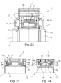
- Fig. 22 the structure of the motor 1 shown is illustrated, which has a multi-phase concept design, with the advantage of being able to connect several power electronics modules 29 via the phase rings 27 and enabling a "smoother" three-phase current.
- this area can also have just three conductors (phase rings 27).
- an additional neutral conductor - i.e. a fourth "phase ring" - may be required.
- the motor 1 is then implemented as a three-phase motor with only 3 phases.
- the phase rings 27 have suitable angled connection fingers 43 where they are connected to the corresponding coils 11. The contact between the two coil ends is made here by soldering/welding/or clamping.
- the individual conductors 27 are much more massive, so that the provision of such connection fingers becomes unrealistic. Instead, the coil ends are then angled accordingly in order to be connected to the correct phase ring 27.
Landscapes
- Engineering & Computer Science (AREA)
- Power Engineering (AREA)
- Microelectronics & Electronic Packaging (AREA)
- Motor Or Generator Cooling System (AREA)
- Windings For Motors And Generators (AREA)
Description
- Die Erfindung betrifft eine Scheibenläufermaschine, vorzugsweise als Axialflussmaschine ausgeführt, für einen Kraftfahrzeugantrieb, mit einem (gesamtheitlich) scheibenförmig ausgebildeten Stator, wobei der Stator mehrere in einer Umfangsrichtung verteilt angeordnete, mittels zumindest eines Halteringes miteinander fest verbundene Kernsegmente sowie mehrere jeweils um ein Kernsegment (unter Ausbildung einer Spule) herum verlaufende Spulenwicklungen aufweist, mit einem relativ zu dem Stator verdrehbar gelagerten Rotor, wobei der Rotor eine erste Rotorscheibe, die zu einer ersten axialen Seite hin neben dem Stator angeordnet ist, sowie eine zweite Rotorscheibe, die zu einer der ersten axialen Seite gegenüberliegenden zweiten axialen Seite hin neben dem Stator angeordnet ist, aufweist, welche Rotorscheiben durch mehrere in einer Umfangsrichtung verteilt angeordnete, die Kernsegmente sowie Spulenwicklungen umfassende Spulen des Stators antreibbar sind, sowie mit einer die Spulen im Betrieb kühlenden Kühleinrichtung.
- Aus dem Stand der Technik sind bereits Scheibenläufermaschinen in unterschiedlichen Ausführungen bekannt. Bspw. offenbart die
WO 2018/ 015293 A1 einen Stator für eine Axialflussmaschine. Hierbei werden zwischen je zwei in Umfangsrichtung benachbarten Spulen Leitbleche eingelegt, die mittels einer Vergussmasse zusammen mit den Spulen zu einer Statorscheibe vergossen werden. Radial außen ist ein wassergekühlter Kanal angeordnet, sodass die Spulen im Betrieb passiv durch die Wärmeabfuhr über die Leitbleche gekühlt werden. - Als Nachteil dieser aus dem Stand der Technik bekannten Ausführung hat es sich jedoch herausgestellt, dass insbesondere wegen der vorhandenen Vergussmasse ein ausreichender Wärmeübertrag von den Spulenwicklungen auf die Leitbleche zur Ausbildung einer besonders leistungsstarken Maschine nur beschränkt bzw. sehr ineffizient ist. Zusätzlich kommt hinzu, dass die Leitbleche eine relativ große Länge aufweisen und die Wärme daher über einen relativ langen radialen Weg nach außen abgeführt werden muss.
- Aus der
WO 2010/092400 A2 ist eine Scheibenläufermaschine gemäß dem Oberbegriff des Anspruchs 1 bekannt. - Bezüglich weiteren Standes der Technik wird auf die
JP 2015 231291 A WO 2008/032430 A1 , dieGB 2 482 928 A EP 3 485 558 A1 verwiesen. - Es ist daher Aufgabe der vorliegenden Erfindung, eine Scheibenläufermaschine zur Verfügung zu stellen, die zur Umsetzung einer möglichst hohen Leistungsdichte mit einer leistungsfähigeren Kühlung ausgestattet ist.
- Dies wird erfindungsgemäß durch die in Anspruch 1 angegebenen Maßnahmen gelöst.
- Der Stator weist ein die Spulenwicklungen aufnehmendes, mit dem zumindest einen Haltering verbundenes Trägerrad auf, wobei das Trägerrad einen zumindest eine der Spulenwicklungen unmittelbar aufnehmenden Kühlkanalabschnitt der Kühleinrichtung (unmittelbar) ausbildet.
- Durch das Vorsehen des Kühlkanalabschnittes der Kühleinrichtung in das Trägerrad und die Aufnahme der Spulenwicklung in dem Kühlkanalabschnitt wird eine Haltefunktion deutlich von einer Dichtfunktion / einer Kühlfluidleitfunktion getrennt. Während bevorzugt der zumindest eine Haltering zusammen mit den Kernsegmenten eine Einheit ausbildet, die im Betrieb sämtliche Antriebskräfte aufnimmt, ist das Trägerrad vorwiegend zur Umleitung des Kühlfluids entlang der Spulenwicklungen ausgebildet. Dadurch ist es möglich, den zumindest einen Haltering aus einem stabilen Metallblech, etwa einem Stahlblech, auszubilden, während das Trägerrad kostengünstig aus einem weniger festen sowie einfacher verarbeitbaren Material, vorzugsweise einem Kunststoffmaterial, ausgebildet ist. Dadurch lässt sich das Trägerrad einfach ausformen und es wird eine Scheibenläufermaschine zur Verfügung gestellt, die einfacher herstellbar ist. Zugleich wird eine direkte Kühlung der Spulen im Betrieb ermöglicht.
- Weitere vorteilhafte Ausführungen sind mit den Unteransprüchen beansprucht und nachfolgend näher erläutert.
- Erfindungsgemäß ist der Kühlkanalabschnitt unmittelbar durch einen die zumindest eine Spulenwicklung aufnehmenden, in einer senkrecht zu einer zentralen Drehachse angeordneten Radialebene umlaufenden / ringförmigen Teilhohlraum des Trägerrades gebildet. Dadurch kann ein Kühlmittel im Betrieb effizient an der Spulenwicklung vorbeigeleitet werden.
- Des Weiteren ist es vorteilhaft, wenn der Teilhohlraum durch zwei radial verlaufende sowie in Umfangsrichtung beabstandete Hohlspeichen des Trägerrades mit gebildet ist, welche Hohlspeichen (mit ihren Innenräumen) in einem, einen Zulauf aufweisenden, ersten radialen Bereich (des Trägerrades) in Umfangsrichtung voneinander getrennt / abgedichtet sind und in einem, zu dem ersten radialen Bereich radial versetzten, vorzugsweise radial nach innen versetzten, zweiten radialen Bereich in Umfangsrichtung miteinander verbunden sind / ineinander übergehen. Dadurch ergibt sich eine geschickte Zirkulation des Kühlmittels im Betrieb der Scheibenläufermaschine.
- Besonders zweckmäßig ist ein Zulauf in dem ersten radialen Bereich zu einer ersten Umfangsseite eines die beiden Hohlspeichen voneinander abtrennenden Dichtelementes mit dem Kühlkanalabschnitt verbunden, während ein Rücklauf zu einer der ersten Umfangsseite gegenüberliegenden zweiten Umfangsseite des Dichtelementes mit dem Kühlkanalabschnitt verbunden ist.
- Ist der Kühlkanalabschnitt über einen axial verlaufenden ersten Verbindungskanal mit einem ringförmigen, zwischen dem Trägerrad und einem ersten Haltering eingeschlossenen / begrenzten Zulaufkanal verbunden, wird der Zulauf geschickt zwischen der Kontur des Halterings und des Trägerrades integriert.
- Demnach ist es auch zweckmäßig, wenn der Kühlkanalabschnitt über einen axial verlaufenden zweiten Verbindungskanal mit einem ringförmigen, zwischen dem Trägerrad und einem zweiten Haltering eingeschlossenen Rücklaufkanal verbunden ist.
- Ist der Kühlkanalabschnitt zu seiner radialen Außenseite hin unmittelbar durch mehrere jeweils mit den Spulenwicklungen verbundene, (in axialer Richtung) gestapelt nebeneinander angeordnete Phasenringe begrenzt, werden auch die Phasenringe auf im Betrieb unmittelbar durch die Kühleinrichtung gekühlt.
- Auf typische Weise ist zwischen je zwei nebeneinander angeordneten Phasenringen eine Isolierung vorgesehen, die die Phasenringe voneinander elektrisch entkoppelt.
- Ist auf den Phasenringen zumindest eine mit den Phasenringen teilweise elektrisch gekoppelte Leistungselektronik angeordnet / fixiert / aufgebracht, wird diese passiv durch die Phasenringe ebenfalls gekühlt.
- Für eine besonders robuste Abstützung der Spulenwicklungen ist es auch von Vorteil, wenn ein eine Spulenwicklung aufnehmender Spulenträger in dem Trägerrad mit fixiert ist.
- Für eine besonders robuste Abstützung ist es von Vorteil, wenn der Spulenträger eine konische Anlagekontur aufweist, die in dem Trägerrad aufgenommen ist. Die konische Anlagekontur ist vorzugsweise zu einer Innenseite des sich ringförmig erstreckenden Spulenträgers umgesetzt und liegt flächig an einer gegensinnigen Gegenkontur des Trägerrades an.
- In anderen Worten ausgedrückt, betrifft die Erfindung somit einen speziellen Aufbau sowie ein spezielles Kühlkonzept eines Scheibenläufers (vorzugsweise als Axialflussmaschine ausgebildet). Eine direkte Kühlung der Spulenwindungen / -wicklungen durch das entsprechende Kühlmedium wird durch das Aufteilen der Funktionen des Drehmomentübertrags / der Drehmomentabstützung sowie der Kühlmittelabdichtung auf zwei verschiedene Komponenten bewerkstelligt. Demnach weist der Aufbau einen Haltering auf, der die Eisenkerne sowie das Drehmoment abstützt, während eine Trägerscheibe (Trägerrad) die Spulenwicklungen aufnimmt. Zusätzlich formt die Trägerscheibe zusammen mit den Phasenringen einen abgedichteten / abgeschlossenen Kanal / Hohlraum für das Kühlmedium.
- Die Erfindung wird nun nachfolgend anhand von Figuren näher erläutert, in welchem Zusammenhang auch unterschiedliche Ausführungsbeispiele beschrieben sind.
- Es zeigen:
- Fig. 1
- eine perspektivische Darstellung einer erfindungsgemäßen, in Längsrichtung geschnittenen Scheibenläufermaschine, ausgebildet nach einem ersten Ausführungsbeispiel,
- Fig. 2
- eine Detailansicht der in Längsrichtung geschnittenen Scheibenläufermaschine nach
Fig. 1 in einem Bereich eines Zulaufkanals und eines Rücklaufkanals einer erfindungsgemäß ausgebildeten Kühleinrichtung, - Fig. 3
- eine perspektivische Darstellung eines in Längsrichtung geschnittenen Trägerrades, wie es in einem in
Fig. 1 eingesetzten Stator integriert ist, wobei ein eine Spulenwicklung aufnehmender Spulenträger zu erkennen ist, - Fig. 4
- eine perspektivische Darstellung des Trägerrades nach
Fig. 3 in einer Vollansicht, - Fig. 5
- eine Schnittdarstellung des Trägerrades entlang der in
Fig. 4 mit "V-V" gekennzeichneten Schnittlinie, wobei mehrere die Spulenwicklungen abschnittsweise aufnehmenden sowie als Kühlkanalabschnitt dienende Hohlspeichen geschnitten sind, - Fig. 6
- eine perspektivische Darstellung eines das Trägerrad mit ausbildenden Schalenelementes,
- Fig. 7
- eine Draufsicht auf eine vereinfacht dargestellt, in der erfindungsgemäßen Scheibenläufermaschine auf mehreren Phasenringen zu platzierenden, zum Ansteuern mehrerer Spulen dienenden Leistungselektronikeinheit,
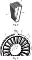
- Fig. 8
- eine perspektivische Darstellung einer Spule mit Spulenträger und Spulenwicklung, wie sie in der Scheibenläufermaschine nach
Fig. 1 eingesetzt ist, - Fig. 9
- eine perspektivische Darstellung eines Unterzusammenbaus aus mehreren in Umfangsrichtung verteilt angeordneten Spulen und mehreren radial außerhalb der Spulen angeordneten, mit den Spulen verbundenen, Phasenringen,
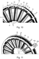
- Fig. 10
- eine perspektivische Darstellung eines Teils des Unterzusammenbaus nach
Fig. 9 , - Fig. 11
- eine perspektivische Darstellung des Unterzusammenbaus nach
Fig. 9 zu einer radialen Außenseite hin, wobei ein Anbringbereich der Leistungselektronikeinheit durch eine strichlierte elliptische Linie gekennzeichnet ist, - Fig. 12
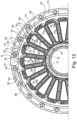
- eine Querschnittsansicht des Trägerrades nach den
Fign. 3 und 4 , wobei mehrere mit einem Zulauf und einem Rücklauf verbundene Kühlkanalabschnitte, innerhalb derer die Spulenwicklungen angeordnet sind, zu erkennen sind, - Fig. 13
- eine perspektivische Darstellung der erfindungsgemäßen Scheibenläufermaschine bei abgenommenen Deckelblechen sowie Rotorscheiben,
- Fig. 14
- eine perspektivische Darstellung eines Unterzusammenbaus aus einem Haltering mit mehreren Hälften mehrerer Kernsegmente,
- Fig. 15
- eine perspektivische Darstellung des Teilzusammenbaus nach
Fig. 14 , in einem Längsschnitt dargestellt, - Fign. 16a
- sowie 16b zwei unterschiedliche perspektivische Darstellungen einer in
Fig. 14 eingesetzten Hälfte eines Kernsegmentes mit entsprechenden Halteblechen, - Fig. 17
- eine perspektivische Darstellung eines Unterzusammenbaus aus einem Haltering mit mehreren in Umfangsrichtung umgesetzten Hälften mehrerer Kernsegmente gemäß einem zweiten Ausführungsbeispiel, wobei sich die Kernsegmente im Aufbau von dem ersten Ausführungsbeispiel unterscheiden,
- Fig. 18
- eine perspektivische Ansicht des Unterzusammenbaus nach
Fig. 17 von einer der inFig. 17 dargestellten Seite abgewandten Seite, - Fig. 19
- eine perspektivische Darstellung des in
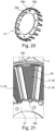
Fig. 17 eingesetzten Halterings, - Fig. 20
- eine perspektivische Darstellung eines neben dem Haltering nach
Fig. 19 ebenfalls inFig. 17 eingesetzten (inneren) Halterings, - Fig. 21
- eine perspektivische Detailansicht des Unterzusammenbaus nach
Fig. 17 seitens einer Kernsegmenthälfte, - Fig. 22
- eine Längsschnittdarstellung einer erfindungsgemäßen Scheibenläufermaschine nach einem dritten Ausführungsbeispiel,
- Fig. 23
- eine detaillierte Längsschnittdarstellung eines Lagerbereiches zwischen einem Rotor und dem Stator der Scheibenläufermaschine nach
Fig. 1 , wobei die Koppelung zweier Rotorscheiben über eine Koppelwelle zu erkennen ist, - Fig. 24
- eine detaillierte Längsschnittdarstellung einer erfindungsgemäßen Scheibenläufermaschine nach einem vierten Ausführungsbeispiel, ebenfalls seitens ihres Lagerungsbereiches, wobei die Koppelwelle nun mit einer durchgängig verlaufenden Verzahnung ausgebildet ist,
- Fig. 25
- eine perspektivische Darstellung einer in dem ersten Ausführungsbeispiel eingesetzten Rotorscheibe,
- Fig. 26
- eine perspektivische Darstellung der in dem ersten Ausführungsbeispiel eingesetzten Koppelwelle,
- Fig. 27
- eine perspektivische Darstellung der Scheibenläufermaschine nach
Fig. 1 von einer ersten axialen Seite, sowie - Fig. 28
- eine perspektivische Darstellung der Scheibenläufermaschine nach
Fig. 1 von einer zweiten axialen Seite. - Die Figuren sind lediglich schematischer Natur und dienen ausschließlich dem Verständnis der Erfindung. Die gleichen Elemente sind mit denselben Bezugszeichen versehen.
- Die erfindungsgemäße Scheibenläufermaschine 1 gemäß einem bevorzugten ersten Ausführungsbeispiel ist in den
Fign. 1 und 2 hinsichtlich ihres prinzipiellen Aufbaus übersichtlich zu erkennen. Die Scheibenläufermaschine 1 ist als eine Axialflussmaschine umgesetzt. Die Scheibenläufermaschine 1 dient bevorzugt zum Einsatz als eine Antriebsmaschine in einem Kraftfahrzeugantrieb. Die Scheibenläufermaschine 1 ist mit einem gesamtheitlich scheibenförmig ausgebildeten Stator 2 ausgestattet. Zudem weist die Scheibenläufermaschine 1 einen Rotor 7 auf. Der Rotor 7 ist um eine zentrale Drehachse 15 drehbar relativ zu dem Stator 2 gelagert. - Die hierin verwendeten Richtungsangaben axial, radial und in Umfangsrichtung beziehen sich auf eine zentrale Drehachse 15 des Rotors 7, sodass unter axialer Richtung / axial eine Richtung entlang / parallel zu der Drehachse 15, unter radialer Richtung / radial eine Richtung senkrecht zu der Drehachse 15 und unter Umfangsrichtung eine Richtung tangential zu einer konzentrisch um die Drehachse 15 herumverlaufenden Kreislinie zu verstehen ist.
- Der Rotor 7 weist eine erste Rotorscheibe 8 auf, die zu einer ersten axialen Seite 10a des Stators 2 hin angeordnet ist sowie eine zweite Rotorscheibe 9 auf, die zu einer zweiten axialen Seite 10b des Stators 2 hin angeordnet ist. In dieser Ausführung weist jede Rotorscheibe 8, 9 einen Flanschbereich 38 auf, in dem mehrere in Umfangsrichtung verteilt angeordnete Aufnahmelöcher 39 zur Aufnahme eines Befestigungselementes, wie einer Schraube umgesetzt sind.
- Die beiden Rotorscheiben 8, 9 sind radial innerhalb des Flanschbereiches 38 über eine Koppelwelle 37 drehfest miteinander verbunden. In dieser Ausführung greift jede Rotorscheibe 8, 9 mit einer radialen Innenverzahnung 40 in eine radiale Außenverzahnung 41 der Koppelwelle 37 ein. Wie in
Fign. 23 und26 zu erkennen, sind die beiden die Außenverzahnungen 41 aufweisenden Bereiche der Koppelwelle 37 voneinander räumlich (axial) getrennt. Gemäß einem weiteren Ausführungsbeispiel, wie es inFig. 24 zu erkennen ist, ist es auch möglich, die Außenverzahnung 41 axial durchgängig verlaufen zu lassen. Gemäß weiteren Ausführungen ist es prinzipiell auch denkbar, jede Rotorscheibe 8, 9 mit einer Außenverzahnung zu versehen und diese in eine Innenverzahnung der Koppelwelle 37 einzuschieben. - Jede Rotorscheibe 8, 9, von denen in
Fig. 25 die erste Rotorscheibe 8 exemplarisch dargestellt ist, weist mehrere in Umfangsrichtung verteilt angeordnete magnetisierbare oder magnetische Platten 42 / Plattenbereiche auf, die im Betrieb mit den nachfolgend näher beschriebenen Spulen 11 einer Spulenanordnung 35 des Stators 2 zusammen wirken. - Mit den
Fign. 3 bis 16b geht auch der nähere Aufbau des erfindungsgemäß ausgebildeten Stators 2 deutlicher hervor. Der Stator 2 ist in einem fertig montierten Zustand gemäß denFign. 1 und 2 prinzipiell scheibenförmig ausgebildet. Der Stator 2 weist im Wesentlichen zwei Hauptkomponenten auf. Eine erste Hauptkomponente des Stators 2 bildet ein Trägerrad 13. Eine zweite Hauptkomponente des Stators 2 bilden zwei Halteringe 3, 4 mit mehreren in Umfangsrichtung verteilt angeordneten Kernsegmenten 5, wie nachfolgend näher beschrieben. - Zunächst wird näher auf den Aufbau des Trägerrades 13 eingegangen, der auch aus
Fig. 4 gut hervorgeht. Das Trägerrad 13 bildet erfindungsgemäß mehrere Kühlkanalabschnitte 14 einer Kühleinrichtung 12 unmittelbar aus. Zugleich nimmt das Trägerrad 13 mehrere Spulenwicklungen 6 mehrerer Spulen 11 auf, die in Umfangsrichtung verteilt angeordnet sind. Jede Spulenwicklung 6 ist im fertig montierten Zustand des Stators 2 folglich Bestandteil einer einzelnen Spule 11. Die Spulenwicklungen 6 sind insbesondere in denFign. 8 bis 11 gut zu erkennen. Jede Spulenwicklung 6 ist auf einem Spulenträger 30 fest aufgenommen und zusammen mit diesem Spulenträger 30 in dem Trägerrad 13 fixiert. Innerhalb jeder Spulenwicklung 6 ist im Betrieb ein Kernsegment 5 eingeschoben. Das Kernsegment 5 ist folglich als Eisenkern umgesetzt. Das Trägerrad 13 ist aus zwei Schalenelementen 33, 34 zusammengesetzt, wovon inFig. 6 ein erstes Schalenelement 33 exemplarisch dargestellt ist. - Jede Spulenwicklung 6 wird mit zwei von einer Vielzahl an Phasenringen 27 verbunden. Jeder Phasenring 27 weist dazu radial nach innen abstehende erste Nasen 43 / Laschen auf, die mit den Enden der Spulenwicklungen 6 verbunden sind (
Fig. 10 ). Radial nach außen abstehende zweite Nasen 44 / Laschen der Phasenringe 27 sind mit mehreren in Umfangsrichtung verteilt angeordneten, unmittelbar auf diesen Phasenringen 27 aufgebrachten Leistungselektronikeinheiten 29 verbunden. Eine Leistungselektronikeinheit 29 ist beispielhaft inFig. 7 dargestellt. Je Spule 11 ist in dieser Ausführung eine Leistungselektronikeinheit 29 vorhanden. Die einzelnen Leistungselektronikeinheit 29 bilden eine gesamtheitliche Leistungselektronik zum Ansteuern einer die Spulen 11 aufweisenden Spulenanordnung 35 aus. - Wie in
Fig. 10 in Verbindung mitFig. 11 angedeutet, ist zwischen je zwei unmittelbar benachbarten Phasenringen 27 eine Isolierung 28 in Form einer Isolierungsscheibe (z.B. Papierdichtung oder Isolierlack auf dem jeweiligen Phasenring 27) angeordnet, die dazu dient, die unmittelbar benachbarten Phasenringe 27 elektrisch voneinander zu entkoppeln. Die Phasenringe 27 sind somit unter Ausbildung eines Stapels übereinander gelegt. Zu je einem Ende des Stapels sind die Phasenringe 27 durch Haltescheiben 45a, 45b fixiert (Fig. 11 ). - Erfindungsgemäß, wie im Zusammenhang mit
Fig. 12 gut zu erkennen, ist in dem Trägerrad 13 unmittelbar der Kühlkanalabschnitt 14 ausgebildet, der unmittelbar an einer Spulenwicklung 6 vorbeigeführt wird bzw. diese Spulenwicklung 6 unmittelbar aufnimmt. Die Spulenwicklung 6 ist in einem durch zwei benachbarte Hohlspeichen 17a, 17b des Trägerrades 13 unmittelbar mit ausgebildeten Teilhohlraum 16 angeordnet. - Ein Teilhohlraum 16 erstreckt sich in der in
Fig. 12 senkrecht zur Drehachse 15 verlaufenden Radialebene vollständig umlaufend / ringförmig. In einem ersten radial außen liegenden Bereich 19 ist der Teilhohlraum 16 durch ein Dichtelement 32 getrennt. Zu einer ersten Umfangsseite des Dichtelementes 32 hin ist ein Zulauf 18 an den Kühlkanalabschnitt 14 angeschlossen, zu einer, der ersten Umfangsseite entgegengesetzten, zweiten Umfangsseite des Dichtelementes 32 hin ist ein Rücklauf 25 an den Kühlkanalabschnitt 14 angeschlossen. Somit befinden sich Zulauf 18 und Rücklauf 25 in dem gemeinsamen (ersten) radialen Bereich 19. - Von dem ersten radialen Bereich 19 erstreckt sich der Teilhohlraum 16 über die beiden Hohlspeichen 17a, 17b, unter Aufnahme der entsprechenden Abschnitte der Spulenwicklung 6, in radialer Richtung nach innen und geht zu einer radialen Innenseite hin in einen zweiten radialen Bereich 20 über. Die beiden Hohlspeichen 17a, 17b sind in dem zweiten radialen Bereich 20 in Umfangsrichtung miteinander verbunden.
- Auf diese Weise wird jede Spulenwicklung 6 in einem Teilhohlraum 16 aufgenommen, wobei die jeweils unmittelbar benachbarten Teilhohlräume 16 (in
Fig. 12 durch einen ersten Teilhohlraum 16a und einen zweiten Teilhohlraum 16b hervorgehoben) durch jeweils eine gemeinsame Hohlspeiche 17a, 17b mit ausgebildet sind. Des Weiteren sei darauf hingewiesen, dass Zulauf 18 und Rücklauf 25 wechselweise angeordnet sind. Demnach ist bspw. in einem ersten Teilhohlraum 16a gemäßFig. 12 der Kühlkanalabschnitt 14 zu der ersten Umfangsseite des Dichtelementes 32 hin an den Zulauf 18 angeschlossen, während ein weiterer Kühlkanalabschnitt 14 in einem zweiten Teilhohlraum 16b zu der zweiten Umfangsseite seines Dichtelementes 32 hin an den Zulauf 18 angeschlossen ist. Dasselbe gilt für die Rückläufe 25, die jeweils auf den anderen Umfangsseiten des Dichtelementes 32 hin an die Kühlkanalabschnitte 14 angeschlossen sind. - Zurückkommend auf die
Fign. 1 und 2 ist zudem zu erkennen, dass ein ringförmiger Zulaufkanal 22 zwischen dem Trägerrad 13 und einem ersten Haltering 3 umgesetzt ist, welcher Zulaufkanal 22 unmittelbar den Zulauf 18 der Kühlkanalabschnitte 14 ausbildet. Der Zulaufkanal 22 ist über jeweils einen ersten axial verlaufenden Verbindungskanal 21 mit einem der Kühlkanalabschnitte 14 verbunden. Ein Rücklaufkanal 24 ist zwischen dem Trägerrad 13 und einem zweiten Haltering 4 unmittelbar ausgebildet, welcher Rücklaufkanal 24 unmittelbar den Rücklauf 25 der Kühlkanalabschnitte 14 ausbildet. Der Rücklaufkanal 24 ist über jeweils einen zweiten axial verlaufenden Verbindungskanal 23 einem der Kühlkanalabschnitte 14 verbunden. - Des Weiteren geht aus den
Fig. 1 und 2 hervor, dass jeder Kühlkanalabschnitt 14 zu einer radialen Außenseite 26 hin unmittelbar durch die Phasenringe 27 begrenzt ist, sodass auch die Phasenringe 27 im Betrieb unmittelbar durch das strömende Kühlmittel gekühlt werden. - Mit den
Fign. 13 bis 16b ist dann der Unterzusammenbau der Kernsegmente 5 mit den Halteringen 3, 4 zu erkennen. Der erste Haltering 3 ist mit mehreren, jeweils an Hälften 49 der Kernsegmente 5 angebrachten ersten Halteblechen 36a verschweißt, hier über eine Laserschweißnaht. Die ersten Haltebleche 36a erstrecken sich bevorzugt gebogen entlang einer gedachten Kreislinie eines Innenumfangs des ersten Halteringes 3. Die Hälften 49 der Kernsegmente 5 an sich sind durch einen aus Blech geformten Grundkörper 46 umgesetzt. - Neben dem radial von außen an dem Grundkörper 46 angebrachten ersten Halteblech 36 ist ein zweites Halteblech 36b vorhanden, das zu einer radialen Innenseite des Grundkörpers 46 angebracht ist. Das zweite Halteblech 36b ist mit einem weiteren (dritten) Haltering 47 verschweißt. Das zweite Halteblech 36b erstreckt sich bevorzugt gebogen entlang einer gedachten Kreislinie eines Außenumfangs des dritten Halteringes 47.
- Auf diese wird auch der zweite Haltering 4 mit weiteren Hälften 49 der Kernsegmente 5 gefertigt. Nach Zusammenbau der Hälften 49 jedes Kernsegmentes 5 ergibt sich der Unterzusammenbau, wie er in
Fig. 13 zu erkennen ist. - In diesem Zusammenhang sei auch auf die
Fign. 17 bis 21 verwiesen, die ein alternatives Ausführungsbeispiel zu diesem Unterzusammenbau darstellen. Demnach ist es prinzipiell auch von Vorteil, wenn jeder Grundkörper 46 aus mehreren in radialer Richtung übereinander gestapelten, gesamtheitlich ein Trapez bildenden (verbackenen) Blechsegmenten ausgebildet ist. Die Blechsegmente sind bevorzugt miteinander sowie mit den Halteblechen 36a, 36b verklebt. In dieser Ausführung sind dann vorzugsweise an dem ersten Haltering 3 bereits die ersten Haltebleche 36a unmittelbar ausgeformt. Wie inFig. 20 zu erkennen ist an dem dritten Haltering 47 auch unmittelbar das jeweilige zweite Halteblech 36b angeformt. - Mit den
Fign. 27 und 28 ist dann die fertige Scheibenläufermaschine 1 gut zu erkennen, wobei zusätzlich von beiden axialen Seiten zwischen dem jeweiligen Flanschbereich 38 und den Halteringen 3, 4 verlaufende Deckelbleche 48a, 48b zur axialen Abdeckung angebracht sind. Die Halteringe 3, 4, 47 sind bevorzugt aus einem V2A- oder V4A-Stahl ausgeformt. - Des Weiteren sei erwähnt, dass die eingesetzten Dichtelemente 32 mit einem Elastomerschlauch zur Abdichtung bzw. Aufteilung des Spulenraumes / des Teilhohlraums 16 und zur Führung des Kühlstroms ausgestattet sind. Der Elastomerschlauch ist über einen Sicherungsstift in dem Trägerrad 13 fixiert. Die durch Dichtelemente 32 bereitgestellte Dichtung ist in weiteren Ausführungen auch unmittelbar an den Kunststoff der Schalenelemente 33, 34 des Trägerrades (vorzugsweise durch 2K-Spritzgusstechnik) angespritzt.
- In anderen Worten ausgedrückt, ist erfindungsgemäß eine Flüssigkeitskühlung 12, bei der das Medium direkt auf die Drähte (der Spulenwicklungen 6) trifft, umgesetzt, wodurch ein hohes Potential geboten ist, die Verlustwärme abzutransportieren. Dadurch werden mittels der Flüssigkeitskühlung 12 die Spulendrähte 6 zu 100% erreicht und gekühlt. Dies ermöglicht es, den Motor 1 mit hohen Strömen zu belasten, was in hohen Motormomenten resultiert. Ein Hauptmerkmal des Motordesigns liegt in der Funktionstrennung zwischen Momentabstützung über Blechteile 3, 4 und der Abdichtung des Kühlmediums mit Bauteilen (Trägerrad 13) aus Kunststoff.
- Der dargestellte Motor 1 besitzt zum Beispiel zwanzig einzelne Spulen 11. Es ist bekannt, dass mindestens 3 Phasen benötigt werden, damit man von "Drehstrom" sprechen kann. Dieser Motor 1 sieht z.B. zehn Phasen vor. Daher werden jeweils zwei Spulen 11, (welche um 180° versetzt - d.h. gegenüberliegend zur Rotationsachse 15 angeordnet sind) mit der gleichen Phase bestromt. Die Phasenringe 27 dienen dazu, die Spulen 11 mit Strom zu versorgen. Jede Spule 11 wird an zwei der Phasenringe 27 angeschlossen. Jeder Phasenring 27 besitzt daher zur Kontaktierung abstehende Anschlussfinger 43, 44. Die radial nach innen anstehende Finger 43 dienen zur Anbindung an den Spulendraht 6, während die nach radial außen abstehenden Finger 44 für die Anbindung an die Leistungselektronik vorgesehen sind. Zusammen ergeben die Phasenringe 27 das Phasenring-Paket, welches im Verbund eine geeignete, gekühlte Außenfläche ergibt, durch welche die Leistungselektronik gekühlt wird.
- Aufgrund der Vielzahl an Phasen, kann die benötigte Leistungselektronik aus zehn kleineren separaten Einheiten 29 bestehen. Diese Einheiten 29 können (auf den Umfang verteilt) außen auf das Phasenpaket 27 platziert werden. Jede Einheit 29 bestromt also zwei Spulen 11. Jede Leistungselektronik-Einheit 29 wird über den Plus- und Minuspol gespeist und jeweils an zwei Phasenringe 27 angebunden. Die Einheiten 29 werden von einer zentralen Steuerelektronik über einen Bus (Strang mit mehreren Signalkabeln) angesteuert. Dabei wird jede Leistungselektronikeinheit 29 zusätzlich mit mindestens einem Steuerkabel aus dem Bus angesteuert. Gemäß der gezeigten Darstellungen nach
Fig. 7 befindet sich die Leistungselektronik im Trockenen. In einer weiteren Variante ist es denkbar, dass sie jedoch auch auf der radial Innenseite des Phasenring-Paketes 27 platziert wird. Somit würde sie direkt vom Kühlmedium umspült und noch effizienter gekühlt. Leistungselektronikeinheit 29 ist mit zwei Batterieanschlüssen (Minus 50a; Plus 50b), einem Signalkabel 51, zwei der Phasenringe 27 und einer Platine 52 dargestellt. - Mit
Fig. 22 wird der gezeigte Aufbau des Motors 1 verdeutlicht, der ein Design eines Vielphasenkonzeptes aufweist, mit dem Vorteil, mehrere Leistungselektronikmodule 29 über die Phasenringe 27 anschließen zu können und einen "glatteren" Drehstrom zu ermöglichen. Statt der benötigten +/- Pole und der vielen Phasenring 27 kann dieser Bereich auch nur noch drei Leiter (Phasenringe 27) aufweisen. Je nach Schaltung der Spulen wird eventuell noch ein zusätzlicher Null-Leiter - also ein vierter "Phasenring" benötigt. Dann ist der Motor 1 als Drehstrommotor mit nur 3 Phasen umgesetzt. Die Phasenringe 27 weisen dort, wo sie mit den entsprechenden Spulen 11 verbunden sind, geeignete abgewinkelte Anschlussfinger 43 auf. Die Kontaktierung der beiden Spulenenden erfolgt hier durch Löt-/ Schweiß- /oder Klemmverbindung. Bei einem beispielsweise 3-Phasen-Konzept fallen die einzelnen Leiter 27 wesentlich massiver aus, so dass die Bereitstellung solcher Anschlussfinger unrealistisch wird. Vielmehr werden dann die Spulenenden entsprechen abgewinkelt um mit dem richtigen Phasenring 27 verbunden. -
- 1
- Scheibenläufermaschine
- 2
- Stator
- 3
- erster Haltering
- 4
- zweiter Haltering
- 5
- Kernsegment
- 6
- Spulenwicklung
- 7
- Rotor
- 8
- erste Rotorscheibe
- 9
- zweite Rotorscheibe
- 10a
- erste Seite
- 10b
- zweite Seite
- 11
- Spulenanordnung
- 12
- Kühleinrichtung
- 13
- Trägerrad
- 14
- Kühlkanalabschnitt
- 15
- Drehachse
- 16
- Teilhohlraum
- 16a
- erster Teilhohlraum
- 16b
- zweiter Teilhohlraum
- 17a
- erste Hohlspeiche
- 17b
- zweite Hohlspeiche
- 18
- Zulauf
- 19
- erster Bereich
- 20
- zweiter Bereich
- 21
- erster Verbindungskanal
- 22
- Zulaufkanal
- 23
- zweiter Verbindungskanal
- 24
- Rücklaufkanal
- 25
- Rücklauf
- 26
- Außenseite
- 27
- Phasenring
- 28
- Isolierung
- 29
- Leistungselektronikeinheit
- 30
- Spulenträger
- 31
- Anlagekontur
- 32
- Dichtelement
- 33
- erstes Schalenelement
- 34
- zweites Schalenelement
- 35
- Spule
- 36a
- erstes Halteblech
- 36b
- zweites Halteblech
- 37
- Koppelwelle
- 38
- Flanschbereich
- 39
- Aufnahmeloch
- 40
- Innenverzahnung
- 41
- Außenverzahnung
- 42
- Platte
- 43
- erste Nase
- 44
- zweite Nase
- 45a
- erste Haltescheibe
- 45b
- zweite Haltescheibe
- 46
- Grundkörper
- 47
- Haltering
- 48a
- erstes Deckelblech
- 48b
- zweites Deckelblech
- 49
- Hälfte
- 50a
- erster Batterieanschluss
- 50b
- zweiter Batterieanschluss
- 51
- Signalkabel
- 52
- Platine
Claims (9)
- Scheibenläufermaschine (1) für einen Kraftfahrzeugantrieb, miteinem scheibenförmig ausgebildeten Stator (2), der mehrere in einer Umfangsrichtung verteilt angeordnete, mittels zumindest eines Halteringes (3, 4) miteinander fest verbundene Kernsegmente (5) und mehrere jeweils um ein Kernsegment (5) herum verlaufende Spulenwicklungen (6) aufweist,einem relativ zu dem Stator (2) verdrehbar gelagerten Rotor (7), der eine zu einer ersten axialen Seite (10a) hin neben dem Stator (2) angeordnete erste Rotorscheibe (8) und eine zu einer der ersten axialen Seite (10a) gegenüberliegenden zweiten axialen Seite (10b) hin neben dem Stator (2) angeordnete zweite Rotorscheibe (9) aufweist, wobei die Rotorscheiben (8, 9) durch mehrere in einer Umfangsrichtung verteilt angeordnete, die Kernsegmente (5) und Spulenwicklungen (6) umfassende Spulen (11) des Stators (2) antreibbar sind, undmit einer die Spulen (11) im Betrieb kühlenden Kühleinrichtung (12),dadurch gekennzeichnet, dassder Stator (2) ein die Spulenwicklungen (6) aufnehmendes, mit dem zumindest einen Haltering (3, 4) verbundenes Trägerrad (13) aufweist,das Trägerrad (13) einen zumindest eine der Spulenwicklungen (6) unmittelbar aufnehmenden Kühlkanalabschnitt (14) der Kühleinrichtung (12) ausbildet,die zumindest eine der Spulenwicklungen (6) in einem durch zwei benachbarte Hohlspeichen (17a, 17b) des Trägerrades (13) unmittelbar mit ausgebildeten Teilhohlraum (16) angeordnet ist, undder Kühlkanalabschnitt (14) unmittelbar durch den die zumindest eine Spulenwicklung (6) aufnehmenden Teilhohlraum (16) gebildet ist, der in einer senkrecht zu einer zentralen Drehachse (15) angeordneten Radialebene umläuft.
- Scheibenläufermaschine (1) nach Anspruch 1, dadurch gekennzeichnet, dass der Teilhohlraum (16) durch zwei radial verlaufende sowie in Umfangsrichtung beabstandete Hohlspeichen (17a, 17b) des Trägerrades (13) mit gebildet ist, wobei die Hohlspeichen (17a, 17b) in einem einen Zulauf (18) aufweisenden ersten radialen Bereich (19) in Umfangsrichtung voneinander getrennt sind und in einem zu dem ersten radialen Bereich (19) radial versetzten zweiten radialen Bereich (20) in Umfangsrichtung miteinander verbunden sind.
- Scheibenläufermaschine (1) nach Anspruch 1 oder 2, dadurch gekennzeichnet, dass der Kühlkanalabschnitt (14) über einen axial verlaufenden ersten Verbindungskanal (21) mit einem ringförmigen, zwischen dem Trägerrad (13) und einem ersten Haltering (3) eingeschlossenen Zulaufkanal (22) verbunden ist.
- Scheibenläufermaschine (1) nach einem der Ansprüche 1 bis 3, dadurch gekennzeichnet, dass der Kühlkanalabschnitt (14) über einen axial verlaufenden zweiten Verbindungskanal (23) mit einem ringförmigen, zwischen dem Trägerrad (13) und einem zweiten Haltering (4) eingeschlossenen Rücklaufkanal (24) verbunden ist.
- Scheibenläufermaschine (1) nach einem der Ansprüche 1 bis 4, dadurch gekennzeichnet, dass der Kühlkanalabschnitt (14) zu seiner radialen Außenseite (26) hin unmittelbar durch mehrere jeweils mit den Spulenwicklungen (6) verbundene, gestapelt nebeneinander angeordnete Phasenringe (27) begrenzt ist.
- Scheibenläufermaschine (1) nach Anspruch 5, dadurch gekennzeichnet, dass jeweils zwei nebeneinander angeordnete Phasenringe (27) durch eine zwischen ihnen vorgesehene Isolierung (28) voneinander elektrisch entkoppelt sind.
- Scheibenläufermaschine (1) nach Anspruch 5 oder 6, dadurch gekennzeichnet, dass auf den Phasenringen (27) zumindest eine mit den Phasenringen (27) teilweise elektrisch gekoppelte Leistungselektronikeinheit (29) angeordnet ist.
- Scheibenläufermaschine (1) nach einem der Ansprüche 1 bis 7, dadurch gekennzeichnet, dass ein eine Spulenwicklung (6) aufnehmender Spulenträger (30) in dem Trägerrad (13) fixiert ist.
- Scheibenläufermaschine (1) nach Anspruch 8, dadurch gekennzeichnet, dass der Spulenträger (30) eine konische Anlagekontur (31) aufweist, die in dem Trägerrad (13) aufgenommen ist.
Applications Claiming Priority (2)
| Application Number | Priority Date | Filing Date | Title |
|---|---|---|---|
| DE102019122314.8A DE102019122314A1 (de) | 2019-08-20 | 2019-08-20 | Scheibenläufermaschine für einen Kraftfahrzeugantrieb |
| PCT/DE2020/100634 WO2021032236A1 (de) | 2019-08-20 | 2020-07-21 | Scheibenläufermaschine für einen kraftfahrzeugantrieb |
Publications (2)
| Publication Number | Publication Date |
|---|---|
| EP4018529A1 EP4018529A1 (de) | 2022-06-29 |
| EP4018529B1 true EP4018529B1 (de) | 2024-09-11 |
Family
ID=71943900
Family Applications (1)
| Application Number | Title | Priority Date | Filing Date |
|---|---|---|---|
| EP20750584.3A Active EP4018529B1 (de) | 2019-08-20 | 2020-07-21 | Scheibenläufermaschine für einen kraftfahrzeugantrieb |
Country Status (5)
| Country | Link |
|---|---|
| US (1) | US12334786B2 (de) |
| EP (1) | EP4018529B1 (de) |
| CN (1) | CN114207994B (de) |
| DE (1) | DE102019122314A1 (de) |
| WO (1) | WO2021032236A1 (de) |
Families Citing this family (26)
| Publication number | Priority date | Publication date | Assignee | Title |
|---|---|---|---|---|
| DE102019125871A1 (de) | 2019-09-25 | 2021-03-25 | Schaeffler Technologies AG & Co. KG | Axialflussmaschine |
| FR3117706B1 (fr) * | 2020-12-10 | 2025-05-02 | Sas Whylot | Stator de moteur électrique comportant un système de refroidissement des bobines par huile. |
| WO2022233356A1 (de) | 2021-05-03 | 2022-11-10 | Schaeffler Technologies AG & Co. KG | Hybridgetriebe sowie antriebsstrang mit hybridgetriebe |
| DE102022106550A1 (de) | 2021-05-03 | 2022-11-03 | Schaeffler Technologies AG & Co. KG | Hybridgetriebe sowie Antriebsstrang mit Hybridgetriebe |
| DE102021114571A1 (de) * | 2021-06-07 | 2022-12-08 | Dr. Ing. H.C. F. Porsche Aktiengesellschaft | Spaltrohrmotor |
| CN118056344A (zh) * | 2021-10-07 | 2024-05-17 | 米巴电动汽车有限公司 | 轴流机 |
| DE102021130345B4 (de) * | 2021-11-19 | 2023-10-12 | David Schoone | Elektromotor, insbesondere für den Einbau in einen Radkörper eines Motorrades |
| DE102021006008A1 (de) | 2021-12-06 | 2023-06-07 | Mercedes-Benz Group AG | Axialflussmaschine für ein Kraftfahrzeug |
| DE102021006602A1 (de) | 2021-12-06 | 2023-06-07 | Mercedes-Benz Group AG | Axialflussmaschine für ein Kraftfahrzeug |
| DE102021215040A1 (de) | 2021-12-27 | 2023-06-29 | Robert Bosch Gesellschaft mit beschränkter Haftung | Stator, Axialflussmaschine und Pumpe |
| DE102022001674B4 (de) | 2022-05-12 | 2024-05-23 | Mercedes-Benz Group AG | Axialflussmaschine für ein Kraftfahrzeug, insbesondere für einen Kraftwagen |
| DE102022205748A1 (de) * | 2022-06-07 | 2023-12-07 | Vitesco Technologies GmbH | Axialflussmaschine mit Statorkühlung und Kraftfahrzeug mit Axialflussmaschine |
| KR20240043949A (ko) * | 2022-09-28 | 2024-04-04 | 현대자동차주식회사 | Afpm 모터 고정자 및 그 제조 방법 |
| DE102022004579B4 (de) * | 2022-12-07 | 2024-12-05 | Mercedes-Benz Group AG | Axialflussmaschine für ein Kraftfahrzeug, insbesondere für einen Kraftwagen |
| FR3144439A1 (fr) * | 2022-12-22 | 2024-06-28 | Valeo Equipements Electriques Moteur | Stator de machine électrique à flux axial |
| FR3146770A1 (fr) | 2023-03-15 | 2024-09-20 | Nidec Psa Emotors | Machine électrique tournante à flux axial |
| DE102023109865A1 (de) * | 2023-04-19 | 2024-10-24 | Schaeffler Technologies AG & Co. KG | Axialflussmaschine mit einem Stator und optimierter Kühlung der Polschuhe |
| DE102023113747A1 (de) * | 2023-05-25 | 2024-11-28 | Schaeffler Technologies AG & Co. KG | Stator mit einem Abstützsteg zwischen Statorzahn und zugehöriger Wicklung und Axialflussmaschine |
| IT202300011754A1 (it) * | 2023-06-08 | 2024-12-08 | Texa Dynamics S R L | Macchina elettrica a flusso assiale provvista di un gruppo statorico e metodo per realizzare un gruppo statorico di una macchina elettrica a flusso assiale |
| FR3151951A1 (fr) * | 2023-08-02 | 2025-02-07 | Valeo Eautomotive Germany Gmbh | Machine électrique tournante à flux axial |
| EP4535614A1 (de) * | 2023-10-02 | 2025-04-09 | Magnax | Axialflussmaschine mit direkter kernkühlung |
| DE102023004139B4 (de) * | 2023-10-13 | 2025-09-04 | Mercedes-Benz Group AG | Verfahren zum Herstellen eines Stators für eine Axialflussmaschine mittels einer Herstellungsvorrichtung, Stator, Axialflussmaschine, sowie Herstellungsvorrichtung |
| FR3162952A1 (fr) * | 2024-05-31 | 2025-12-05 | Ampere Sas | Dispositif de refroidissement pour une machine électrique à flux axial |
| DE102024002000A1 (de) * | 2024-06-19 | 2025-12-24 | Mercedes-Benz Group AG | Axialflussmaschine für ein Kraftfahrzeug sowie Kraftfahrzeug |
| CN223285641U (zh) * | 2024-07-15 | 2025-08-29 | 宁德时代(上海)智能科技有限公司 | 定子、电机、电驱动装置、电驱动系统及电动设备 |
| CN120049658B (zh) * | 2025-02-13 | 2026-01-27 | 智新科技股份有限公司 | 一种高转矩密度轴向磁通电机的转子系统 |
Citations (1)
| Publication number | Priority date | Publication date | Assignee | Title |
|---|---|---|---|---|
| EP3485558B1 (de) * | 2016-07-18 | 2019-12-18 | Universiteit Gent | Stator für eine axialflussmaschine und verfahren zur herstellung davon |
Family Cites Families (24)
| Publication number | Priority date | Publication date | Assignee | Title |
|---|---|---|---|---|
| GB9510994D0 (en) * | 1995-05-31 | 1995-07-26 | Turbo Genset The Company Ltd | Rotary electrical machines |
| EP0917757B1 (de) | 1996-08-09 | 2004-10-13 | The Turbo Genset Company Limited | Rotierende elektrische maschinen |
| US7211919B2 (en) * | 1999-08-16 | 2007-05-01 | American Superconductor Corporation | Thermally-conductive stator support structure |
| CN100358225C (zh) * | 2002-06-26 | 2007-12-26 | 阿莫泰克有限公司 | 径向铁芯型双转子无刷直流电动机及其制造方法 |
| US7332837B2 (en) * | 2003-08-11 | 2008-02-19 | General Motors Corporation | Cooling and handling of reaction torque for an axial flux motor |
| US7701101B2 (en) * | 2003-09-02 | 2010-04-20 | Cummins Generator Technologies Limited | Alternator assembly |
| JP4611857B2 (ja) * | 2005-10-11 | 2011-01-12 | 本田技研工業株式会社 | モータ |
| WO2008032430A1 (en) * | 2006-09-13 | 2008-03-20 | Ntn Corporation | Motor-integrated magnetic bearing device |
| IT1392107B1 (it) * | 2008-11-28 | 2012-02-09 | Lucchi | Parte statorica di macchina elettrica a flusso assiale con sistema di raffreddamento a liquido. |
| GB0902393D0 (en) * | 2009-02-13 | 2009-04-01 | Isis Innovation | Elaectric machine - modular |
| GB0902394D0 (en) | 2009-02-13 | 2009-04-01 | Isis Innovation | Electric machine- cooling |
| US10574110B2 (en) * | 2010-04-28 | 2020-02-25 | Launchpoint Technologies, Inc. | Lightweight and efficient electrical machine and method of manufacture |
| GB201013881D0 (en) * | 2010-08-19 | 2010-10-06 | Oxford Yasa Motors Ltd | Electric machine - construction |
| DE102014205034A1 (de) | 2014-03-18 | 2015-09-24 | Robert Bosch Gmbh | Statoreinheit für eine elektrische Maschine sowie elektrische Maschine |
| JP6270213B2 (ja) | 2014-06-05 | 2018-01-31 | 株式会社神戸製鋼所 | 電動機 |
| CA2894943A1 (en) * | 2014-06-20 | 2015-12-20 | Lucchi R. Elettromeccanica Srl | Axial-flux electric machine with winding rotor and method for the production thereof |
| US9948157B2 (en) * | 2015-01-19 | 2018-04-17 | Lucchi R. Elettromeccanica Srl | Containing casing for a stator of an electric machine and stator assembly using said casing |
| US10186922B2 (en) * | 2017-01-11 | 2019-01-22 | Infinitum Electric Inc. | System and apparatus for axial field rotary energy device |
| DE102017215835A1 (de) | 2017-09-07 | 2019-03-07 | Brose Fahrzeugteile GmbH & Co. Kommanditgesellschaft, Würzburg | Fluidgekühlte elektrische Maschine |
| US11482905B2 (en) * | 2017-11-28 | 2022-10-25 | Highlands Power, Inc. | Stator having housing-integrated bus bars and internal cooling jacket |
| DE102019125871A1 (de) | 2019-09-25 | 2021-03-25 | Schaeffler Technologies AG & Co. KG | Axialflussmaschine |
| DE102020101149A1 (de) * | 2019-12-04 | 2021-06-10 | Schaeffler Technologies AG & Co. KG | Axialflussmaschine mit mechanisch fixierten Statorkernen mit radial verlaufenden Blechsegmenten |
| DE102020101148A1 (de) * | 2019-12-04 | 2021-06-10 | Schaeffler Technologies AG & Co. KG | Axialflussmaschine mit radial verlaufende Blechsegmente aufweisendem Stator |
| US12261491B2 (en) * | 2022-04-12 | 2025-03-25 | Hamilton Sundstrand Corporation | Aircraft electric motor |
-
2019
- 2019-08-20 DE DE102019122314.8A patent/DE102019122314A1/de not_active Withdrawn
-
2020
- 2020-07-21 CN CN202080056300.5A patent/CN114207994B/zh active Active
- 2020-07-21 WO PCT/DE2020/100634 patent/WO2021032236A1/de not_active Ceased
- 2020-07-21 US US17/632,249 patent/US12334786B2/en active Active
- 2020-07-21 EP EP20750584.3A patent/EP4018529B1/de active Active
Patent Citations (1)
| Publication number | Priority date | Publication date | Assignee | Title |
|---|---|---|---|---|
| EP3485558B1 (de) * | 2016-07-18 | 2019-12-18 | Universiteit Gent | Stator für eine axialflussmaschine und verfahren zur herstellung davon |
Also Published As
| Publication number | Publication date |
|---|---|
| US12334786B2 (en) | 2025-06-17 |
| CN114207994B (zh) | 2024-08-20 |
| EP4018529A1 (de) | 2022-06-29 |
| DE102019122314A1 (de) | 2021-03-11 |
| US20220278579A1 (en) | 2022-09-01 |
| WO2021032236A1 (de) | 2021-02-25 |
| CN114207994A (zh) | 2022-03-18 |
Similar Documents
| Publication | Publication Date | Title |
|---|---|---|
| EP4018529B1 (de) | Scheibenläufermaschine für einen kraftfahrzeugantrieb | |
| WO2020099048A1 (de) | Stützeinrichtung für einen rotor einer fremderregten innenläufer-synchronmaschine bestehend aus einem stützring und einer sternscheibe | |
| EP2242165B1 (de) | Läufer für eine elektrische Maschine | |
| DE3907860C2 (de) | Läufer für eine rotierende elektrische Maschine | |
| EP2523319B1 (de) | Zylindrischer Linearmotor mit geringen Rastkräften | |
| EP4320709A1 (de) | Stator einer elektrischen axialflussmaschine und axialflussmaschine | |
| EP4555603B1 (de) | Stator für eine elektrische axialflussmaschine, verfahren zum herstellen eines solchen stators und elektrische axialflussmaschine mit einem solchen stator | |
| EP3989408A1 (de) | Rotor für eine elektrische maschine, elektrische maschine für ein fahrzeug und verfahren zur herstellung eines rotors für eine elektrische maschine | |
| DE69014642T2 (de) | Läufer mit reduzierten ventilationsverlusten. | |
| DE102017215835A1 (de) | Fluidgekühlte elektrische Maschine | |
| DE102021101914A1 (de) | Stator und Verfahren zur Herstellung eines Stators | |
| WO2008071147A2 (de) | Elektrische maschine und verfahren zum herstellen einer solchen | |
| EP1385252B1 (de) | Elektrische Maschine mit Aussenläufer und einer gegossenen Nabe | |
| DE102014205034A1 (de) | Statoreinheit für eine elektrische Maschine sowie elektrische Maschine | |
| EP2523321A1 (de) | Zylindrischer Linearmotor mit geblechtem Ständer | |
| WO2013023908A2 (de) | Aussenläufermaschine mit statorsegmenten | |
| DE102020109980A1 (de) | Stator für eine elektrische Maschine und elektrische Maschine | |
| DE3314426A1 (de) | Schenkelpollaeufer fuer eine elektrische rotationsmaschine | |
| EP3813237B1 (de) | Spulenmodul für eine elektrische maschine | |
| DE102005005953A1 (de) | Bürstenlose Gleichstrommaschine sowie Rückschlussringpaket, Zahnkranzpaket und Kopfteil einer Gleichstrommaschine sowie Verfahren zur Herstellung einer bürstenlosen Gleichstrommaschine | |
| DE102010003246B4 (de) | Transversalflussmaschine | |
| DE102020126184B4 (de) | Elektrische Maschine | |
| DE102023108723A1 (de) | Rotor für eine elektrische Traktionsmaschine eines Kraftfahrzeugs sowie elektrische Traktionsmaschine | |
| EP4084288B1 (de) | Spulenmodul für eine elektrische maschine | |
| EP3035497B1 (de) | Karusselltür |
Legal Events
| Date | Code | Title | Description |
|---|---|---|---|
| STAA | Information on the status of an ep patent application or granted ep patent |
Free format text: STATUS: UNKNOWN |
|
| STAA | Information on the status of an ep patent application or granted ep patent |
Free format text: STATUS: THE INTERNATIONAL PUBLICATION HAS BEEN MADE |
|
| PUAI | Public reference made under article 153(3) epc to a published international application that has entered the european phase |
Free format text: ORIGINAL CODE: 0009012 |
|
| STAA | Information on the status of an ep patent application or granted ep patent |
Free format text: STATUS: REQUEST FOR EXAMINATION WAS MADE |
|
| 17P | Request for examination filed |
Effective date: 20220321 |
|
| AK | Designated contracting states |
Kind code of ref document: A1 Designated state(s): AL AT BE BG CH CY CZ DE DK EE ES FI FR GB GR HR HU IE IS IT LI LT LU LV MC MK MT NL NO PL PT RO RS SE SI SK SM TR |
|
| DAV | Request for validation of the european patent (deleted) | ||
| DAX | Request for extension of the european patent (deleted) | ||
| P01 | Opt-out of the competence of the unified patent court (upc) registered |
Effective date: 20230522 |
|
| STAA | Information on the status of an ep patent application or granted ep patent |
Free format text: STATUS: EXAMINATION IS IN PROGRESS |
|
| 17Q | First examination report despatched |
Effective date: 20240404 |
|
| GRAP | Despatch of communication of intention to grant a patent |
Free format text: ORIGINAL CODE: EPIDOSNIGR1 |
|
| STAA | Information on the status of an ep patent application or granted ep patent |
Free format text: STATUS: GRANT OF PATENT IS INTENDED |
|
| GRAS | Grant fee paid |
Free format text: ORIGINAL CODE: EPIDOSNIGR3 |
|
| INTG | Intention to grant announced |
Effective date: 20240515 |
|
| GRAA | (expected) grant |
Free format text: ORIGINAL CODE: 0009210 |
|
| STAA | Information on the status of an ep patent application or granted ep patent |
Free format text: STATUS: THE PATENT HAS BEEN GRANTED |
|
| AK | Designated contracting states |
Kind code of ref document: B1 Designated state(s): AL AT BE BG CH CY CZ DE DK EE ES FI FR GB GR HR HU IE IS IT LI LT LU LV MC MK MT NL NO PL PT RO RS SE SI SK SM TR |
|
| REG | Reference to a national code |
Ref country code: GB Ref legal event code: FG4D Free format text: NOT ENGLISH |
|
| REG | Reference to a national code |
Ref country code: CH Ref legal event code: EP |
|
| REG | Reference to a national code |
Ref country code: DE Ref legal event code: R096 Ref document number: 502020009215 Country of ref document: DE |
|
| REG | Reference to a national code |
Ref country code: IE Ref legal event code: FG4D Free format text: LANGUAGE OF EP DOCUMENT: GERMAN |
|
| REG | Reference to a national code |
Ref country code: LT Ref legal event code: MG9D |
|
| PG25 | Lapsed in a contracting state [announced via postgrant information from national office to epo] |
Ref country code: NO Free format text: LAPSE BECAUSE OF FAILURE TO SUBMIT A TRANSLATION OF THE DESCRIPTION OR TO PAY THE FEE WITHIN THE PRESCRIBED TIME-LIMIT Effective date: 20241211 |
|
| REG | Reference to a national code |
Ref country code: NL Ref legal event code: MP Effective date: 20240911 |
|
| PG25 | Lapsed in a contracting state [announced via postgrant information from national office to epo] |
Ref country code: GR Free format text: LAPSE BECAUSE OF FAILURE TO SUBMIT A TRANSLATION OF THE DESCRIPTION OR TO PAY THE FEE WITHIN THE PRESCRIBED TIME-LIMIT Effective date: 20241212 Ref country code: FI Free format text: LAPSE BECAUSE OF FAILURE TO SUBMIT A TRANSLATION OF THE DESCRIPTION OR TO PAY THE FEE WITHIN THE PRESCRIBED TIME-LIMIT Effective date: 20240911 |
|
| PG25 | Lapsed in a contracting state [announced via postgrant information from national office to epo] |
Ref country code: BG Free format text: LAPSE BECAUSE OF FAILURE TO SUBMIT A TRANSLATION OF THE DESCRIPTION OR TO PAY THE FEE WITHIN THE PRESCRIBED TIME-LIMIT Effective date: 20240911 |
|
| PG25 | Lapsed in a contracting state [announced via postgrant information from national office to epo] |
Ref country code: LV Free format text: LAPSE BECAUSE OF FAILURE TO SUBMIT A TRANSLATION OF THE DESCRIPTION OR TO PAY THE FEE WITHIN THE PRESCRIBED TIME-LIMIT Effective date: 20240911 |
|
| PG25 | Lapsed in a contracting state [announced via postgrant information from national office to epo] |
Ref country code: HR Free format text: LAPSE BECAUSE OF FAILURE TO SUBMIT A TRANSLATION OF THE DESCRIPTION OR TO PAY THE FEE WITHIN THE PRESCRIBED TIME-LIMIT Effective date: 20240911 |
|
| PG25 | Lapsed in a contracting state [announced via postgrant information from national office to epo] |
Ref country code: RS Free format text: LAPSE BECAUSE OF FAILURE TO SUBMIT A TRANSLATION OF THE DESCRIPTION OR TO PAY THE FEE WITHIN THE PRESCRIBED TIME-LIMIT Effective date: 20241211 Ref country code: ES Free format text: LAPSE BECAUSE OF FAILURE TO SUBMIT A TRANSLATION OF THE DESCRIPTION OR TO PAY THE FEE WITHIN THE PRESCRIBED TIME-LIMIT Effective date: 20240911 |
|
| PG25 | Lapsed in a contracting state [announced via postgrant information from national office to epo] |
Ref country code: RS Free format text: LAPSE BECAUSE OF FAILURE TO SUBMIT A TRANSLATION OF THE DESCRIPTION OR TO PAY THE FEE WITHIN THE PRESCRIBED TIME-LIMIT Effective date: 20241211 Ref country code: NO Free format text: LAPSE BECAUSE OF FAILURE TO SUBMIT A TRANSLATION OF THE DESCRIPTION OR TO PAY THE FEE WITHIN THE PRESCRIBED TIME-LIMIT Effective date: 20241211 Ref country code: LV Free format text: LAPSE BECAUSE OF FAILURE TO SUBMIT A TRANSLATION OF THE DESCRIPTION OR TO PAY THE FEE WITHIN THE PRESCRIBED TIME-LIMIT Effective date: 20240911 Ref country code: HR Free format text: LAPSE BECAUSE OF FAILURE TO SUBMIT A TRANSLATION OF THE DESCRIPTION OR TO PAY THE FEE WITHIN THE PRESCRIBED TIME-LIMIT Effective date: 20240911 Ref country code: GR Free format text: LAPSE BECAUSE OF FAILURE TO SUBMIT A TRANSLATION OF THE DESCRIPTION OR TO PAY THE FEE WITHIN THE PRESCRIBED TIME-LIMIT Effective date: 20241212 Ref country code: FI Free format text: LAPSE BECAUSE OF FAILURE TO SUBMIT A TRANSLATION OF THE DESCRIPTION OR TO PAY THE FEE WITHIN THE PRESCRIBED TIME-LIMIT Effective date: 20240911 Ref country code: ES Free format text: LAPSE BECAUSE OF FAILURE TO SUBMIT A TRANSLATION OF THE DESCRIPTION OR TO PAY THE FEE WITHIN THE PRESCRIBED TIME-LIMIT Effective date: 20240911 Ref country code: BG Free format text: LAPSE BECAUSE OF FAILURE TO SUBMIT A TRANSLATION OF THE DESCRIPTION OR TO PAY THE FEE WITHIN THE PRESCRIBED TIME-LIMIT Effective date: 20240911 |
|
| PG25 | Lapsed in a contracting state [announced via postgrant information from national office to epo] |
Ref country code: NL Free format text: LAPSE BECAUSE OF FAILURE TO SUBMIT A TRANSLATION OF THE DESCRIPTION OR TO PAY THE FEE WITHIN THE PRESCRIBED TIME-LIMIT Effective date: 20240911 |
|
| PG25 | Lapsed in a contracting state [announced via postgrant information from national office to epo] |
Ref country code: PT Free format text: LAPSE BECAUSE OF FAILURE TO SUBMIT A TRANSLATION OF THE DESCRIPTION OR TO PAY THE FEE WITHIN THE PRESCRIBED TIME-LIMIT Effective date: 20250113 Ref country code: IS Free format text: LAPSE BECAUSE OF FAILURE TO SUBMIT A TRANSLATION OF THE DESCRIPTION OR TO PAY THE FEE WITHIN THE PRESCRIBED TIME-LIMIT Effective date: 20250111 |
|
| PG25 | Lapsed in a contracting state [announced via postgrant information from national office to epo] |
Ref country code: SM Free format text: LAPSE BECAUSE OF FAILURE TO SUBMIT A TRANSLATION OF THE DESCRIPTION OR TO PAY THE FEE WITHIN THE PRESCRIBED TIME-LIMIT Effective date: 20240911 Ref country code: RO Free format text: LAPSE BECAUSE OF FAILURE TO SUBMIT A TRANSLATION OF THE DESCRIPTION OR TO PAY THE FEE WITHIN THE PRESCRIBED TIME-LIMIT Effective date: 20240911 |
|
| PG25 | Lapsed in a contracting state [announced via postgrant information from national office to epo] |
Ref country code: EE Free format text: LAPSE BECAUSE OF FAILURE TO SUBMIT A TRANSLATION OF THE DESCRIPTION OR TO PAY THE FEE WITHIN THE PRESCRIBED TIME-LIMIT Effective date: 20240911 |
|
| PG25 | Lapsed in a contracting state [announced via postgrant information from national office to epo] |
Ref country code: PL Free format text: LAPSE BECAUSE OF FAILURE TO SUBMIT A TRANSLATION OF THE DESCRIPTION OR TO PAY THE FEE WITHIN THE PRESCRIBED TIME-LIMIT Effective date: 20240911 Ref country code: CZ Free format text: LAPSE BECAUSE OF FAILURE TO SUBMIT A TRANSLATION OF THE DESCRIPTION OR TO PAY THE FEE WITHIN THE PRESCRIBED TIME-LIMIT Effective date: 20240911 |
|
| PG25 | Lapsed in a contracting state [announced via postgrant information from national office to epo] |
Ref country code: IT Free format text: LAPSE BECAUSE OF FAILURE TO SUBMIT A TRANSLATION OF THE DESCRIPTION OR TO PAY THE FEE WITHIN THE PRESCRIBED TIME-LIMIT Effective date: 20240911 Ref country code: SK Free format text: LAPSE BECAUSE OF FAILURE TO SUBMIT A TRANSLATION OF THE DESCRIPTION OR TO PAY THE FEE WITHIN THE PRESCRIBED TIME-LIMIT Effective date: 20240911 |
|
| REG | Reference to a national code |
Ref country code: DE Ref legal event code: R097 Ref document number: 502020009215 Country of ref document: DE |
|
| PG25 | Lapsed in a contracting state [announced via postgrant information from national office to epo] |
Ref country code: DK Free format text: LAPSE BECAUSE OF FAILURE TO SUBMIT A TRANSLATION OF THE DESCRIPTION OR TO PAY THE FEE WITHIN THE PRESCRIBED TIME-LIMIT Effective date: 20240911 |
|
| PLBE | No opposition filed within time limit |
Free format text: ORIGINAL CODE: 0009261 |
|
| STAA | Information on the status of an ep patent application or granted ep patent |
Free format text: STATUS: NO OPPOSITION FILED WITHIN TIME LIMIT |
|
| 26N | No opposition filed |
Effective date: 20250612 |
|
| PG25 | Lapsed in a contracting state [announced via postgrant information from national office to epo] |
Ref country code: SE Free format text: LAPSE BECAUSE OF FAILURE TO SUBMIT A TRANSLATION OF THE DESCRIPTION OR TO PAY THE FEE WITHIN THE PRESCRIBED TIME-LIMIT Effective date: 20240911 |
|
| PGFP | Annual fee paid to national office [announced via postgrant information from national office to epo] |
Ref country code: DE Payment date: 20250919 Year of fee payment: 6 |
|
| PGFP | Annual fee paid to national office [announced via postgrant information from national office to epo] |
Ref country code: GB Payment date: 20250724 Year of fee payment: 6 |
|
| PGFP | Annual fee paid to national office [announced via postgrant information from national office to epo] |
Ref country code: FR Payment date: 20250725 Year of fee payment: 6 |
|
| REG | Reference to a national code |
Ref country code: CH Ref legal event code: H13 Free format text: ST27 STATUS EVENT CODE: U-0-0-H10-H13 (AS PROVIDED BY THE NATIONAL OFFICE) Effective date: 20260224 |
|
| PG25 | Lapsed in a contracting state [announced via postgrant information from national office to epo] |
Ref country code: LU Free format text: LAPSE BECAUSE OF NON-PAYMENT OF DUE FEES Effective date: 20250721 |
|
| REG | Reference to a national code |
Ref country code: BE Ref legal event code: MM Effective date: 20250731 |
|
| PG25 | Lapsed in a contracting state [announced via postgrant information from national office to epo] |
Ref country code: BE Free format text: LAPSE BECAUSE OF NON-PAYMENT OF DUE FEES Effective date: 20250731 |
|
| PG25 | Lapsed in a contracting state [announced via postgrant information from national office to epo] |
Ref country code: CH Free format text: LAPSE BECAUSE OF NON-PAYMENT OF DUE FEES Effective date: 20250731 |