EP4018529B1 - Machine à rotor à disque pour entraînement de véhicule automobile - Google Patents
Machine à rotor à disque pour entraînement de véhicule automobile Download PDFInfo
- Publication number
- EP4018529B1 EP4018529B1 EP20750584.3A EP20750584A EP4018529B1 EP 4018529 B1 EP4018529 B1 EP 4018529B1 EP 20750584 A EP20750584 A EP 20750584A EP 4018529 B1 EP4018529 B1 EP 4018529B1
- Authority
- EP
- European Patent Office
- Prior art keywords
- carrier wheel
- disc rotor
- rotor machine
- stator
- coil
- Prior art date
- Legal status (The legal status is an assumption and is not a legal conclusion. Google has not performed a legal analysis and makes no representation as to the accuracy of the status listed.)
- Active
Links
Images






Classifications
-
- H—ELECTRICITY
- H02—GENERATION; CONVERSION OR DISTRIBUTION OF ELECTRIC POWER
- H02K—DYNAMO-ELECTRIC MACHINES
- H02K1/00—Details of the magnetic circuit
- H02K1/06—Details of the magnetic circuit characterised by the shape, form or construction
- H02K1/12—Stationary parts of the magnetic circuit
- H02K1/18—Means for mounting or fastening magnetic stationary parts on to, or to, the stator structures
- H02K1/182—Means for mounting or fastening magnetic stationary parts on to, or to, the stator structures to stators axially facing the rotor, i.e. with axial or conical air gap
-
- H—ELECTRICITY
- H02—GENERATION; CONVERSION OR DISTRIBUTION OF ELECTRIC POWER
- H02K—DYNAMO-ELECTRIC MACHINES
- H02K1/00—Details of the magnetic circuit
- H02K1/06—Details of the magnetic circuit characterised by the shape, form or construction
- H02K1/12—Stationary parts of the magnetic circuit
- H02K1/20—Stationary parts of the magnetic circuit with channels or ducts for flow of cooling medium
-
- H—ELECTRICITY
- H02—GENERATION; CONVERSION OR DISTRIBUTION OF ELECTRIC POWER
- H02K—DYNAMO-ELECTRIC MACHINES
- H02K1/00—Details of the magnetic circuit
- H02K1/06—Details of the magnetic circuit characterised by the shape, form or construction
- H02K1/22—Rotating parts of the magnetic circuit
- H02K1/27—Rotor cores with permanent magnets
- H02K1/2793—Rotors axially facing stators
- H02K1/2795—Rotors axially facing stators the rotor consisting of two or more circumferentially positioned magnets
- H02K1/2798—Rotors axially facing stators the rotor consisting of two or more circumferentially positioned magnets where both axial sides of the stator face a rotor
-
- H—ELECTRICITY
- H02—GENERATION; CONVERSION OR DISTRIBUTION OF ELECTRIC POWER
- H02K—DYNAMO-ELECTRIC MACHINES
- H02K11/00—Structural association of dynamo-electric machines with electric components or with devices for shielding, monitoring or protection
- H02K11/30—Structural association with control circuits or drive circuits
- H02K11/33—Drive circuits, e.g. power electronics
-
- H—ELECTRICITY
- H02—GENERATION; CONVERSION OR DISTRIBUTION OF ELECTRIC POWER
- H02K—DYNAMO-ELECTRIC MACHINES
- H02K21/00—Synchronous motors having permanent magnets; Synchronous generators having permanent magnets
- H02K21/12—Synchronous motors having permanent magnets; Synchronous generators having permanent magnets with stationary armatures and rotating magnets
- H02K21/24—Synchronous motors having permanent magnets; Synchronous generators having permanent magnets with stationary armatures and rotating magnets with magnets axially facing the armatures, e.g. hub-type cycle dynamos
-
- H—ELECTRICITY
- H02—GENERATION; CONVERSION OR DISTRIBUTION OF ELECTRIC POWER
- H02K—DYNAMO-ELECTRIC MACHINES
- H02K3/00—Details of windings
- H02K3/04—Windings characterised by the conductor shape, form or construction, e.g. with bar conductors
- H02K3/24—Windings characterised by the conductor shape, form or construction, e.g. with bar conductors with channels or ducts for cooling medium between the conductors
-
- H—ELECTRICITY
- H02—GENERATION; CONVERSION OR DISTRIBUTION OF ELECTRIC POWER
- H02K—DYNAMO-ELECTRIC MACHINES
- H02K3/00—Details of windings
- H02K3/04—Windings characterised by the conductor shape, form or construction, e.g. with bar conductors
- H02K3/28—Layout of windings or of connections between windings
-
- H—ELECTRICITY
- H02—GENERATION; CONVERSION OR DISTRIBUTION OF ELECTRIC POWER
- H02K—DYNAMO-ELECTRIC MACHINES
- H02K3/00—Details of windings
- H02K3/46—Fastening of windings on the stator or rotor structure
- H02K3/52—Fastening salient pole windings or connections thereto
- H02K3/521—Fastening salient pole windings or connections thereto applicable to stators only
- H02K3/522—Fastening salient pole windings or connections thereto applicable to stators only for generally annular cores with salient poles
-
- H—ELECTRICITY
- H02—GENERATION; CONVERSION OR DISTRIBUTION OF ELECTRIC POWER
- H02K—DYNAMO-ELECTRIC MACHINES
- H02K3/00—Details of windings
- H02K3/46—Fastening of windings on the stator or rotor structure
- H02K3/47—Air-gap windings, i.e. iron-free windings
Definitions
- the invention relates to a disc rotor machine, preferably designed as an axial flux machine, for a motor vehicle drive, with a (whole) disc-shaped stator, wherein the stator has a plurality of core segments distributed in a circumferential direction, firmly connected to one another by means of at least one retaining ring, and a plurality of coil windings each running around a core segment (forming a coil), with a rotor mounted so as to be rotatable relative to the stator, wherein the rotor has a first rotor disk, which is arranged next to the stator on a first axial side, and a second rotor disk, which is arranged next to the stator on a second axial side opposite the first axial side, which rotor disks can be driven by a plurality of coils of the stator, which are arranged distributed in a circumferential direction and comprise the core segments and coil windings, and with a cooling device which cools the coils during operation.
- Disc rotor machines in various designs are already known from the state of the art.
- the WO 2018/ 015293 A1 a stator for an axial flow machine.
- Guide plates are inserted between two adjacent coils in the circumferential direction, which are then cast together with the coils to form a stator disk using a casting compound.
- a water-cooled channel is arranged radially on the outside, so that the coils are cooled passively during operation by the heat dissipation via the guide plates.
- JP 2015 231291 A the WO 2008/032430 A1 , the GB 2 482 928 A and the EP 3 485 558 A1 referred to.
- the stator has a carrier wheel which receives the coil windings and is connected to the at least one retaining ring, wherein the carrier wheel (directly) forms a cooling channel section of the cooling device which directly receives at least one of the coil windings.
- the carrier wheel By providing the cooling channel section of the cooling device in the carrier wheel and accommodating the coil winding in the cooling channel section, a holding function is clearly separated from a sealing function/cooling fluid conduction function. While the at least one retaining ring together with the core segments preferably forms a unit that absorbs all driving forces during operation, the carrier wheel is designed primarily to redirect the cooling fluid along the coil windings. This makes it possible to form the at least one retaining ring from a stable metal sheet, such as a steel sheet, while the carrier wheel is inexpensively formed from a less solid and easier to process material, preferably a plastic material. This makes it easy to shape the carrier wheel and provides a disc rotor machine that is easier to manufacture. At the same time, direct cooling of the coils during operation is possible.
- the cooling channel section is formed directly by a partial cavity of the carrier wheel which accommodates at least one coil winding and which runs around/is ring-shaped in a radial plane arranged perpendicular to a central axis of rotation. This allows a coolant to be efficiently guided past the coil winding during operation.
- the partial cavity is formed by two radially extending hollow spokes of the carrier wheel that are spaced apart in the circumferential direction, which hollow spokes (with their interiors) are separated/sealed from one another in the circumferential direction in a first radial region (of the carrier wheel) that has an inlet and are connected to one another/merge into one another in the circumferential direction in a second radial region that is radially offset from the first radial region, preferably radially offset inwards.
- an inlet in the first radial region prefferably be connected to the cooling channel section to a first circumferential side of a sealing element separating the two hollow spokes from one another, while a return line to a second circumferential side of the sealing element opposite the first circumferential side is connected to the cooling channel section.
- cooling channel section is connected via an axially extending first connecting channel to an annular inlet channel enclosed/limited between the carrier wheel and a first retaining ring, the inlet is cleverly integrated between the contour of the retaining ring and the carrier wheel.
- cooling channel section is connected via an axially extending second connecting channel to an annular return channel enclosed between the carrier wheel and a second retaining ring.
- the cooling channel section is directly delimited on its radial outer side by several phase rings, each connected to the coil windings and arranged stacked next to one another (in the axial direction), the phase rings are also directly cooled by the cooling device during operation.
- insulation is provided between two phase rings arranged next to each other, which electrically decouples the phase rings from each other.
- At least one power electronics unit that is partially electrically coupled to the phase rings is arranged/fixed/applied, it is also passively cooled by the phase rings.
- the coil carrier has a conical contact contour that is accommodated in the carrier wheel.
- the conical contact contour is preferably implemented on an inner side of the ring-shaped coil carrier and lies flat against an opposite counter contour of the carrier wheel.
- the invention relates to a special structure and a special cooling concept of a disc rotor (preferably designed as an axial flow machine).
- Direct cooling of the coil turns/windings by the corresponding cooling medium is achieved by dividing the functions of torque transmission/torque support and coolant sealing into two different components.
- the structure has a retaining ring that supports the iron cores and the torque, while a carrier disk (carrier wheel) holds the coil windings.
- the carrier disk together with the phase rings forms a sealed/closed channel/cavity for the cooling medium.
- the disc rotor machine 1 according to the invention according to a preferred first embodiment is shown in the Figs. 1 and 2 in terms of its basic structure.
- the disc rotor machine 1 is implemented as an axial flow machine.
- the disc rotor machine 1 is preferably used as a drive machine in a motor vehicle drive.
- the disc rotor machine 1 is equipped with a stator 2 that is entirely disc-shaped.
- the disc rotor machine 1 also has a rotor 7.
- the rotor 7 is mounted so that it can rotate about a central axis of rotation 15 relative to the stator 2.
- the directions axial, radial and circumferential used herein refer to a central axis of rotation 15 of the rotor 7, so that the axial direction / axial is to be understood as a direction along / parallel to the axis of rotation 15, the radial direction / radial is to be understood as a direction perpendicular to the axis of rotation 15 and the circumferential direction is to be understood as a direction tangential to a circular line running concentrically around the axis of rotation 15.
- the rotor 7 has a first rotor disk 8, which is arranged towards a first axial side 10a of the stator 2, and a second rotor disk 9, which is arranged towards a second axial side 10b of the stator 2.
- each rotor disk 8, 9 has a flange region 38 in which a plurality of receiving holes 39 distributed in the circumferential direction are implemented for receiving a fastening element, such as a screw.
- each rotor disk 8, 9 engages with a radial internal toothing 40 in a radial external toothing 41 of the coupling shaft 37.
- the two areas of the coupling shaft 37 having the external teeth 41 are spatially (axially) separated from each other.
- the external toothing 41 run axially continuously. According to further explanations, it is also conceivable in principle, to provide each rotor disk 8, 9 with an external toothing and to insert this into an internal toothing of the coupling shaft 37.
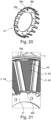
- Each rotor disk 8, 9, of which Fig. 25 the first rotor disk 8 is shown as an example, has a plurality of magnetizable or magnetic plates 42 / plate regions distributed in the circumferential direction, which interact during operation with the coils 11 of a coil arrangement 35 of the stator 2, described in more detail below.
- the detailed structure of the stator 2 designed according to the invention also becomes clearer.
- the stator 2 is in a fully assembled state according to the Figs. 1 and 2 basically disk-shaped.
- the stator 2 essentially has two main components.
- a first main component of the stator 2 is a carrier wheel 13.
- a second main component of the stator 2 is formed by two retaining rings 3, 4 with several core segments 5 distributed in the circumferential direction, as described in more detail below.
- the carrier wheel 13 directly forms several cooling channel sections 14 of a cooling device 12.
- the carrier wheel 13 accommodates several coil windings 6 of several coils 11, which are distributed in the circumferential direction.
- Each coil winding 6 is therefore part of an individual coil 11 in the fully assembled state of the stator 2.
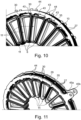
- the coil windings 6 are in particular in the Figs. 8 to 11 can be clearly seen.
- Each coil winding 6 is firmly held on a coil carrier 30 and fixed together with this coil carrier 30 in the carrier wheel 13.
- a core segment 5 is inserted during operation.
- the core segment 5 is thus implemented as an iron core.
- the carrier wheel 13 is composed of two shell elements 33, 34, of which Fig.6 a first shell element 33 is shown as an example.
- Each coil winding 6 is connected to two of a plurality of phase rings 27.
- Each phase ring 27 has first lugs 43 / Tabs that are connected to the ends of the coil windings 6 ( Fig.10 ).
- Radially outwardly projecting second lugs 44 / tabs of the phase rings 27 are connected to several power electronics units 29 arranged distributed in the circumferential direction and mounted directly on these phase rings 27.
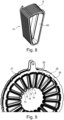
- a power electronics unit 29 is shown by way of example in Fig.7 shown. In this embodiment, there is a power electronics unit 29 for each coil 11.
- the individual power electronics units 29 form an overall power electronics system for controlling a coil arrangement 35 having the coils 11.
- an insulation 28 in the form of an insulation disk e.g. paper seal or insulating varnish on the respective phase ring 27
- an insulation disk e.g. paper seal or insulating varnish on the respective phase ring 27
- the phase rings 27 are thus placed on top of one another to form a stack.
- the phase rings 27 are fixed to one end of the stack by holding disks 45a, 45b ( Fig. 11 ).
- the cooling channel section 14 is formed directly in the carrier wheel 13, which is guided directly past a coil winding 6 or directly receives this coil winding 6.
- the coil winding 6 is arranged in a partial cavity 16 formed directly by two adjacent hollow spokes 17a, 17b of the carrier wheel 13.
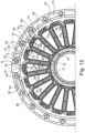
- a partial cavity 16 extends in the Fig. 12 completely circumferential/annular in the radial plane running perpendicular to the axis of rotation 15.
- the partial cavity 16 is separated by a sealing element 32.
- An inlet 18 is connected to the cooling channel section 14 towards a first circumferential side of the sealing element 32, and a return 25 is connected to the cooling channel section 14 towards a second circumferential side of the sealing element 32 opposite the first circumferential side.
- the inlet 18 and return 25 are thus located in the common (first) radial region 19.
- the partial cavity 16 extends over the two hollow spokes 17a, 17b, accommodating the corresponding sections of the coil winding 6, in the radial direction inwards and merges into a second radial region 20 towards a radial inner side.
- the two hollow spokes 17a, 17b are connected to one another in the circumferential direction in the second radial region 20.
- each coil winding 6 is accommodated in a partial cavity 16, whereby the immediately adjacent partial cavities 16 (in Fig. 12 by a first partial cavity 16a and a second partial cavity 16b) are formed by a common hollow spoke 17a, 17b.
- the inlet 18 and return 25 are arranged alternately. Accordingly, for example, in a first partial cavity 16a according to Fig. 12 the cooling channel section 14 is connected to the inlet 18 on the first circumferential side of the sealing element 32, while a further cooling channel section 14 is connected to the inlet 18 on the second circumferential side of its sealing element 32 in a second partial cavity 16b.
- the returns 25, which are each connected to the cooling channel sections 14 on the other circumferential sides of the sealing element 32.
- annular inlet channel 22 is implemented between the carrier wheel 13 and a first retaining ring 3, which inlet channel 22 directly forms the inlet 18 of the cooling channel sections 14.
- the inlet channel 22 is connected to one of the cooling channel sections 14 via a first axially extending connecting channel 21.
- a return channel 24 is formed directly between the carrier wheel 13 and a second retaining ring 4, which return channel 24 directly forms the return 25 of the cooling channel sections 14.
- the return channel 24 is connected to one of the cooling channel sections 14 via a second axially extending connecting channel 23.
- each cooling channel section 14 is directly delimited by the phase rings 27 towards a radial outer side 26, so that the phase rings 27 are also directly cooled by the flowing coolant during operation.
- the first retaining ring 3 is welded to several first retaining plates 36a, each attached to halves 49 of the core segments 5, here via a laser weld seam.
- the first retaining plates 36a preferably extend in a curved manner along an imaginary circular line of an inner circumference of the first retaining ring 3.
- the halves 49 of the core segments 5 themselves are implemented by a base body 46 formed from sheet metal.
- a second retaining plate 36b which is attached to a radial inner side of the base body 46.
- the second retaining plate 36b is welded to a further (third) retaining ring 47.
- the second retaining plate 36b preferably extends in a curved manner along an imaginary circular line of an outer circumference of the third retaining ring 47.
- the second retaining ring 4 is also manufactured on this with further halves 49 of the core segments 5. After assembling the halves 49 of each core segment 5, the sub-assembly results as shown in Fig. 13 can be recognized.
- each base body 46 is formed from several sheet metal segments stacked on top of one another in the radial direction and forming a trapezoid (baked together).
- the sheet metal segments are preferably glued to one another and to the retaining plates 36a, 36b.
- the first retaining plates 36a are then preferably formed directly on the first retaining ring 3.
- the respective second retaining plate 36b is also directly formed on the third retaining ring 47.
- the finished disc rotor machine 1 can then be clearly seen, with additionally from both axial sides between the respective flange area 38 and the retaining rings 3, 4 are provided with cover plates 48a, 48b for axial coverage.
- the retaining rings 3, 4, 47 are preferably made of V2A or V4A steel.
- sealing elements 32 used are equipped with an elastomer hose for sealing or dividing the coil space / partial cavity 16 and for guiding the cooling flow.
- the elastomer hose is fixed in the carrier wheel 13 via a locking pin.
- the seal provided by sealing elements 32 is also molded directly onto the plastic of the shell elements 33, 34 of the carrier wheel (preferably using 2K injection molding technology).
- a liquid cooling system 12 is implemented in which the medium directly hits the wires (of the coil windings 6), which offers a high potential for dissipating the waste heat.
- the coil wires 6 are 100% reached and cooled by means of the liquid cooling system 12. This makes it possible to load the motor 1 with high currents, which results in high motor torques.
- a main feature of the motor design is the functional separation between torque support via sheet metal parts 3, 4 and the sealing of the cooling medium with components (carrier wheel 13) made of plastic.
- the motor 1 shown for example, has twenty individual coils 11. It is known that at least 3 phases are required in order to be able to speak of "three-phase current". This motor 1, for example, has ten phases. Therefore, two coils 11 (which are offset by 180° - i.e. arranged opposite to the axis of rotation 15) are each supplied with current with the same phase.
- the phase rings 27 serve to supply the coils 11 with current. Each coil 11 is connected to two of the phase rings 27.
- Each phase ring 27 therefore has protruding connection fingers 43, 44 for contacting.
- the radially inwardly projecting fingers 43 serve to connect to the coil wire 6, while the radially outwardly projecting fingers 44 are intended for connection to the power electronics. Together, the phase rings 27 form the phase ring package, which in combination forms a suitable, cooled outer surface through which the power electronics are cooled.
- the required power electronics can consist of ten smaller separate units 29. These units 29 can be placed (distributed around the circumference) on the outside of the phase package 27. Each unit 29 thus supplies current to two coils 11. Each power electronics unit 29 is fed via the positive and negative poles and is connected to two phase rings 27. The units 29 are controlled by a central control electronics unit via a bus (string with several signal cables). Each power electronics unit 29 is also controlled with at least one control cable from the bus. According to the illustrations shown according to Fig.7 the power electronics are in a dry place. In another variant, it is conceivable that they are also placed on the radial inside of the phase ring package 27. This would mean that they would be directly surrounded by the cooling medium and cooled even more efficiently. Power electronics unit 29 is shown with two battery connections (minus 50a; plus 50b), a signal cable 51, two of the phase rings 27 and a circuit board 52.
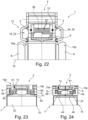
- Fig. 22 the structure of the motor 1 shown is illustrated, which has a multi-phase concept design, with the advantage of being able to connect several power electronics modules 29 via the phase rings 27 and enabling a "smoother" three-phase current.
- this area can also have just three conductors (phase rings 27).
- an additional neutral conductor - i.e. a fourth "phase ring" - may be required.
- the motor 1 is then implemented as a three-phase motor with only 3 phases.
- the phase rings 27 have suitable angled connection fingers 43 where they are connected to the corresponding coils 11. The contact between the two coil ends is made here by soldering/welding/or clamping.
- the individual conductors 27 are much more massive, so that the provision of such connection fingers becomes unrealistic. Instead, the coil ends are then angled accordingly in order to be connected to the correct phase ring 27.
Landscapes
- Engineering & Computer Science (AREA)
- Power Engineering (AREA)
- Microelectronics & Electronic Packaging (AREA)
- Motor Or Generator Cooling System (AREA)
- Windings For Motors And Generators (AREA)
Claims (9)
- Machine à rotor à disque (1) pour entraînement de véhicule automobile, comportantun stator (2) réalisé en forme de disque, qui présente une pluralité de segments de noyau (5) disposés de façon à être répartis dans une direction circonférentielle et reliés fixement les uns aux autres au moyen d'au moins un anneau de retenue (3, 4), et une pluralité d'enroulements de bobines (6) s'étendant chacun autour d'un segment de noyau (5),un rotor (7) monté rotatif par rapport au stator (2), qui présente un premier disque de rotor (8) disposé à côté du stator (2) vers un premier côté axial (10a) et un second disque de rotor (9) disposé à côté du stator (2) vers un second côté axial (10b) opposé au premier côté axial (10a), les disques de rotor (8, 9) pouvant être entraînés par plusieurs bobines (11) du stator (2) disposées de façon à être réparties dans une direction circonférentielle et comprenant les segments de noyau (5) et les enroulements de bobines (6), etcomportant un dispositif de refroidissement (12) qui refroidit les bobines (11) pendant le fonctionnement,caractérisée en ce quele stator (2) présente une roue porteuse (13) qui reçoit les enroulements de bobines (6) et qui est reliée à l'au moins un anneau de retenue (3, 4),la roue porteuse (13) forme une section de canal de refroidissement (14) du dispositif de refroidissement (12) qui reçoit directement au moins un des enroulements de bobines (6),l'au moins un des enroulements de bobines (6) est disposé dans une cavité partielle (16) formée directement par deux rayons creux adjacents (17a, 17b) de la roue porteuse (13), etla section de canal de refroidissement (14) est formée directement par la cavité partielle (16) qui reçoit l'au moins un enroulement de bobine (6) et qui tourne dans un plan radial disposé perpendiculairement à un axe de rotation central (15).
- Machine à rotor à disque (1) selon la revendication 1, caractérisée en ce que la cavité partielle (16) est formée par deux rayons creux (17a, 17b) s'étendant radialement et espacés dans la direction circonférentielle de la roue porteuse (13), les rayons creux (17a, 17b) se trouvant dans une première zone radiale (19) présentant une entrée (18) étant séparés les uns des autres dans la direction circonférentielle et étant reliés les uns aux autres dans la direction circonférentielle dans une seconde zone radiale (20) qui est radialement décalée par rapport à la première zone radiale (19).
- Machine à rotor à disque (1) selon la revendication 1 ou 2, caractérisée en ce que la section de canal de refroidissement (14) est reliée par un premier canal de liaison (21) s'étendant axialement à un canal d'entrée annulaire (22) inclus entre la roue porteuse (13) et un premier anneau de retenue (3).
- Machine à rotor à disque (1) selon l'une quelconque des revendications 1 à 3, caractérisée en ce que la section de canal de refroidissement (14) est reliée par l'intermédiaire d'un second canal de liaison (23) s'étendant axialement à un canal de retour annulaire (24) inclus entre la roue porteuse (13) et un second anneau de retenue (4).
- Machine à rotor à disque (1) selon l'une quelconque des revendications 1 à 4, caractérisée en ce que la section de canal de refroidissement (14) est délimitée directement vers son côté extérieur radial (26) par une pluralité d'anneaux de phase (27) qui sont reliés aux enroulements de bobines (6) et disposés empilés les uns à côté des autres.
- Machine à rotor à disque (1) selon la revendication 5, caractérisée en ce que deux anneaux de phase (27) disposés l'un à côté de l'autre sont électriquement découplés l'un de l'autre par une isolation (28) prévue entre eux.
- Machine à rotor à disque (1) selon la revendication 5 ou 6, caractérisée en ce qu'au moins une unité électronique de puissance (29), partiellement couplée électriquement aux anneaux de phase (27), est disposée sur les anneaux de phase (27).
- Machine à rotor à disque (1) selon l'une quelconque des revendications 1 à 7, caractérisée en ce qu'un support de bobine (30) recevant un enroulement de bobine (6) est fixé dans la roue porteuse (13).
- Machine à rotor à disque (1) selon la revendication 8, caractérisée en ce que le support de bobine (30) présente un contour d'appui conique (31) qui est reçu dans la roue porteuse (13).
Applications Claiming Priority (2)
| Application Number | Priority Date | Filing Date | Title |
|---|---|---|---|
| DE102019122314.8A DE102019122314A1 (de) | 2019-08-20 | 2019-08-20 | Scheibenläufermaschine für einen Kraftfahrzeugantrieb |
| PCT/DE2020/100634 WO2021032236A1 (fr) | 2019-08-20 | 2020-07-21 | Machine à rotor à disque pour entraînement de véhicule automobile |
Publications (2)
| Publication Number | Publication Date |
|---|---|
| EP4018529A1 EP4018529A1 (fr) | 2022-06-29 |
| EP4018529B1 true EP4018529B1 (fr) | 2024-09-11 |
Family
ID=71943900
Family Applications (1)
| Application Number | Title | Priority Date | Filing Date |
|---|---|---|---|
| EP20750584.3A Active EP4018529B1 (fr) | 2019-08-20 | 2020-07-21 | Machine à rotor à disque pour entraînement de véhicule automobile |
Country Status (5)
| Country | Link |
|---|---|
| US (1) | US12334786B2 (fr) |
| EP (1) | EP4018529B1 (fr) |
| CN (1) | CN114207994B (fr) |
| DE (1) | DE102019122314A1 (fr) |
| WO (1) | WO2021032236A1 (fr) |
Families Citing this family (26)
| Publication number | Priority date | Publication date | Assignee | Title |
|---|---|---|---|---|
| DE102019125871A1 (de) | 2019-09-25 | 2021-03-25 | Schaeffler Technologies AG & Co. KG | Axialflussmaschine |
| FR3117706B1 (fr) * | 2020-12-10 | 2025-05-02 | Sas Whylot | Stator de moteur électrique comportant un système de refroidissement des bobines par huile. |
| WO2022233356A1 (fr) | 2021-05-03 | 2022-11-10 | Schaeffler Technologies AG & Co. KG | Transmission hybride et chaîne cinématique à transmission |
| DE102022106550A1 (de) | 2021-05-03 | 2022-11-03 | Schaeffler Technologies AG & Co. KG | Hybridgetriebe sowie Antriebsstrang mit Hybridgetriebe |
| DE102021114571A1 (de) * | 2021-06-07 | 2022-12-08 | Dr. Ing. H.C. F. Porsche Aktiengesellschaft | Spaltrohrmotor |
| CN118056344A (zh) * | 2021-10-07 | 2024-05-17 | 米巴电动汽车有限公司 | 轴流机 |
| DE102021130345B4 (de) * | 2021-11-19 | 2023-10-12 | David Schoone | Elektromotor, insbesondere für den Einbau in einen Radkörper eines Motorrades |
| DE102021006008A1 (de) | 2021-12-06 | 2023-06-07 | Mercedes-Benz Group AG | Axialflussmaschine für ein Kraftfahrzeug |
| DE102021006602A1 (de) | 2021-12-06 | 2023-06-07 | Mercedes-Benz Group AG | Axialflussmaschine für ein Kraftfahrzeug |
| DE102021215040A1 (de) | 2021-12-27 | 2023-06-29 | Robert Bosch Gesellschaft mit beschränkter Haftung | Stator, Axialflussmaschine und Pumpe |
| DE102022001674B4 (de) | 2022-05-12 | 2024-05-23 | Mercedes-Benz Group AG | Axialflussmaschine für ein Kraftfahrzeug, insbesondere für einen Kraftwagen |
| DE102022205748A1 (de) * | 2022-06-07 | 2023-12-07 | Vitesco Technologies GmbH | Axialflussmaschine mit Statorkühlung und Kraftfahrzeug mit Axialflussmaschine |
| KR20240043949A (ko) * | 2022-09-28 | 2024-04-04 | 현대자동차주식회사 | Afpm 모터 고정자 및 그 제조 방법 |
| DE102022004579B4 (de) * | 2022-12-07 | 2024-12-05 | Mercedes-Benz Group AG | Axialflussmaschine für ein Kraftfahrzeug, insbesondere für einen Kraftwagen |
| FR3144439A1 (fr) * | 2022-12-22 | 2024-06-28 | Valeo Equipements Electriques Moteur | Stator de machine électrique à flux axial |
| FR3146770A1 (fr) | 2023-03-15 | 2024-09-20 | Nidec Psa Emotors | Machine électrique tournante à flux axial |
| DE102023109865A1 (de) * | 2023-04-19 | 2024-10-24 | Schaeffler Technologies AG & Co. KG | Axialflussmaschine mit einem Stator und optimierter Kühlung der Polschuhe |
| DE102023113747A1 (de) * | 2023-05-25 | 2024-11-28 | Schaeffler Technologies AG & Co. KG | Stator mit einem Abstützsteg zwischen Statorzahn und zugehöriger Wicklung und Axialflussmaschine |
| IT202300011754A1 (it) * | 2023-06-08 | 2024-12-08 | Texa Dynamics S R L | Macchina elettrica a flusso assiale provvista di un gruppo statorico e metodo per realizzare un gruppo statorico di una macchina elettrica a flusso assiale |
| FR3151951A1 (fr) * | 2023-08-02 | 2025-02-07 | Valeo Eautomotive Germany Gmbh | Machine électrique tournante à flux axial |
| EP4535614A1 (fr) * | 2023-10-02 | 2025-04-09 | Magnax | Machine à flux axial avec refroidissement direct du noyau |
| DE102023004139B4 (de) * | 2023-10-13 | 2025-09-04 | Mercedes-Benz Group AG | Verfahren zum Herstellen eines Stators für eine Axialflussmaschine mittels einer Herstellungsvorrichtung, Stator, Axialflussmaschine, sowie Herstellungsvorrichtung |
| FR3162952A1 (fr) * | 2024-05-31 | 2025-12-05 | Ampere Sas | Dispositif de refroidissement pour une machine électrique à flux axial |
| DE102024002000A1 (de) * | 2024-06-19 | 2025-12-24 | Mercedes-Benz Group AG | Axialflussmaschine für ein Kraftfahrzeug sowie Kraftfahrzeug |
| CN223285641U (zh) * | 2024-07-15 | 2025-08-29 | 宁德时代(上海)智能科技有限公司 | 定子、电机、电驱动装置、电驱动系统及电动设备 |
| CN120049658B (zh) * | 2025-02-13 | 2026-01-27 | 智新科技股份有限公司 | 一种高转矩密度轴向磁通电机的转子系统 |
Citations (1)
| Publication number | Priority date | Publication date | Assignee | Title |
|---|---|---|---|---|
| EP3485558B1 (fr) * | 2016-07-18 | 2019-12-18 | Universiteit Gent | Stator pour une machine à flux axial et son procédé de production |
Family Cites Families (24)
| Publication number | Priority date | Publication date | Assignee | Title |
|---|---|---|---|---|
| GB9510994D0 (en) * | 1995-05-31 | 1995-07-26 | Turbo Genset The Company Ltd | Rotary electrical machines |
| EP0917757B1 (fr) | 1996-08-09 | 2004-10-13 | The Turbo Genset Company Limited | Machine electrique rotative |
| US7211919B2 (en) * | 1999-08-16 | 2007-05-01 | American Superconductor Corporation | Thermally-conductive stator support structure |
| CN100358225C (zh) * | 2002-06-26 | 2007-12-26 | 阿莫泰克有限公司 | 径向铁芯型双转子无刷直流电动机及其制造方法 |
| US7332837B2 (en) * | 2003-08-11 | 2008-02-19 | General Motors Corporation | Cooling and handling of reaction torque for an axial flux motor |
| US7701101B2 (en) * | 2003-09-02 | 2010-04-20 | Cummins Generator Technologies Limited | Alternator assembly |
| JP4611857B2 (ja) * | 2005-10-11 | 2011-01-12 | 本田技研工業株式会社 | モータ |
| WO2008032430A1 (fr) * | 2006-09-13 | 2008-03-20 | Ntn Corporation | Dispositif à coussinet magnétique intégré à un moteur |
| IT1392107B1 (it) * | 2008-11-28 | 2012-02-09 | Lucchi | Parte statorica di macchina elettrica a flusso assiale con sistema di raffreddamento a liquido. |
| GB0902393D0 (en) * | 2009-02-13 | 2009-04-01 | Isis Innovation | Elaectric machine - modular |
| GB0902394D0 (en) | 2009-02-13 | 2009-04-01 | Isis Innovation | Electric machine- cooling |
| US10574110B2 (en) * | 2010-04-28 | 2020-02-25 | Launchpoint Technologies, Inc. | Lightweight and efficient electrical machine and method of manufacture |
| GB201013881D0 (en) * | 2010-08-19 | 2010-10-06 | Oxford Yasa Motors Ltd | Electric machine - construction |
| DE102014205034A1 (de) | 2014-03-18 | 2015-09-24 | Robert Bosch Gmbh | Statoreinheit für eine elektrische Maschine sowie elektrische Maschine |
| JP6270213B2 (ja) | 2014-06-05 | 2018-01-31 | 株式会社神戸製鋼所 | 電動機 |
| CA2894943A1 (fr) * | 2014-06-20 | 2015-12-20 | Lucchi R. Elettromeccanica Srl | Machine electrique a flux axial dotee d'un rotor d'enroulement et sa methode de production |
| US9948157B2 (en) * | 2015-01-19 | 2018-04-17 | Lucchi R. Elettromeccanica Srl | Containing casing for a stator of an electric machine and stator assembly using said casing |
| US10186922B2 (en) * | 2017-01-11 | 2019-01-22 | Infinitum Electric Inc. | System and apparatus for axial field rotary energy device |
| DE102017215835A1 (de) | 2017-09-07 | 2019-03-07 | Brose Fahrzeugteile GmbH & Co. Kommanditgesellschaft, Würzburg | Fluidgekühlte elektrische Maschine |
| US11482905B2 (en) * | 2017-11-28 | 2022-10-25 | Highlands Power, Inc. | Stator having housing-integrated bus bars and internal cooling jacket |
| DE102019125871A1 (de) | 2019-09-25 | 2021-03-25 | Schaeffler Technologies AG & Co. KG | Axialflussmaschine |
| DE102020101149A1 (de) * | 2019-12-04 | 2021-06-10 | Schaeffler Technologies AG & Co. KG | Axialflussmaschine mit mechanisch fixierten Statorkernen mit radial verlaufenden Blechsegmenten |
| DE102020101148A1 (de) * | 2019-12-04 | 2021-06-10 | Schaeffler Technologies AG & Co. KG | Axialflussmaschine mit radial verlaufende Blechsegmente aufweisendem Stator |
| US12261491B2 (en) * | 2022-04-12 | 2025-03-25 | Hamilton Sundstrand Corporation | Aircraft electric motor |
-
2019
- 2019-08-20 DE DE102019122314.8A patent/DE102019122314A1/de not_active Withdrawn
-
2020
- 2020-07-21 CN CN202080056300.5A patent/CN114207994B/zh active Active
- 2020-07-21 WO PCT/DE2020/100634 patent/WO2021032236A1/fr not_active Ceased
- 2020-07-21 US US17/632,249 patent/US12334786B2/en active Active
- 2020-07-21 EP EP20750584.3A patent/EP4018529B1/fr active Active
Patent Citations (1)
| Publication number | Priority date | Publication date | Assignee | Title |
|---|---|---|---|---|
| EP3485558B1 (fr) * | 2016-07-18 | 2019-12-18 | Universiteit Gent | Stator pour une machine à flux axial et son procédé de production |
Also Published As
| Publication number | Publication date |
|---|---|
| US12334786B2 (en) | 2025-06-17 |
| CN114207994B (zh) | 2024-08-20 |
| EP4018529A1 (fr) | 2022-06-29 |
| DE102019122314A1 (de) | 2021-03-11 |
| US20220278579A1 (en) | 2022-09-01 |
| WO2021032236A1 (fr) | 2021-02-25 |
| CN114207994A (zh) | 2022-03-18 |
Similar Documents
| Publication | Publication Date | Title |
|---|---|---|
| EP4018529B1 (fr) | Machine à rotor à disque pour entraînement de véhicule automobile | |
| WO2020099048A1 (fr) | Dispositif de support conçu pour un rotor d'une machine synchrone à rotor interne à excitation séparée comprenant un anneau de support et un disque en étoile | |
| EP2242165B1 (fr) | Rotor pour une machine électrique | |
| DE3907860C2 (de) | Läufer für eine rotierende elektrische Maschine | |
| EP2523319B1 (fr) | Moteur linéaire cylindrique à faible pulsation de couple | |
| EP4320709A1 (fr) | Stator de machine électrique à flux axial et machine à flux axial | |
| EP4555603B1 (fr) | Stator pour machine électrique à flux axial, procédé de fabrication d'un tel stator et machine électrique à flux axial avec un tel stator | |
| EP3989408A1 (fr) | Rotor pour une machine électrique, machine électrique pour un véhicule et procédé de fabrication d'un rotor pour une machine électrique | |
| DE69014642T2 (de) | Läufer mit reduzierten ventilationsverlusten. | |
| DE102017215835A1 (de) | Fluidgekühlte elektrische Maschine | |
| DE102021101914A1 (de) | Stator und Verfahren zur Herstellung eines Stators | |
| WO2008071147A2 (fr) | Moteur électrique et procédé de fabrication | |
| EP1385252B1 (fr) | Machine électrique avec rotor extérieur et moyeu moulé | |
| DE102014205034A1 (de) | Statoreinheit für eine elektrische Maschine sowie elektrische Maschine | |
| EP2523321A1 (fr) | Moteur linéaire cylindrique doté d'un pied en tôle | |
| WO2013023908A2 (fr) | Machine à rotor externe et à segments statoriques | |
| DE102020109980A1 (de) | Stator für eine elektrische Maschine und elektrische Maschine | |
| DE3314426A1 (de) | Schenkelpollaeufer fuer eine elektrische rotationsmaschine | |
| EP3813237B1 (fr) | Module de bobine pour une machine électrique | |
| DE102005005953A1 (de) | Bürstenlose Gleichstrommaschine sowie Rückschlussringpaket, Zahnkranzpaket und Kopfteil einer Gleichstrommaschine sowie Verfahren zur Herstellung einer bürstenlosen Gleichstrommaschine | |
| DE102010003246B4 (de) | Transversalflussmaschine | |
| DE102020126184B4 (de) | Elektrische Maschine | |
| DE102023108723A1 (de) | Rotor für eine elektrische Traktionsmaschine eines Kraftfahrzeugs sowie elektrische Traktionsmaschine | |
| EP4084288B1 (fr) | Module de bobine pour une machine électrique | |
| EP3035497B1 (fr) | Porte à tambour |
Legal Events
| Date | Code | Title | Description |
|---|---|---|---|
| STAA | Information on the status of an ep patent application or granted ep patent |
Free format text: STATUS: UNKNOWN |
|
| STAA | Information on the status of an ep patent application or granted ep patent |
Free format text: STATUS: THE INTERNATIONAL PUBLICATION HAS BEEN MADE |
|
| PUAI | Public reference made under article 153(3) epc to a published international application that has entered the european phase |
Free format text: ORIGINAL CODE: 0009012 |
|
| STAA | Information on the status of an ep patent application or granted ep patent |
Free format text: STATUS: REQUEST FOR EXAMINATION WAS MADE |
|
| 17P | Request for examination filed |
Effective date: 20220321 |
|
| AK | Designated contracting states |
Kind code of ref document: A1 Designated state(s): AL AT BE BG CH CY CZ DE DK EE ES FI FR GB GR HR HU IE IS IT LI LT LU LV MC MK MT NL NO PL PT RO RS SE SI SK SM TR |
|
| DAV | Request for validation of the european patent (deleted) | ||
| DAX | Request for extension of the european patent (deleted) | ||
| P01 | Opt-out of the competence of the unified patent court (upc) registered |
Effective date: 20230522 |
|
| STAA | Information on the status of an ep patent application or granted ep patent |
Free format text: STATUS: EXAMINATION IS IN PROGRESS |
|
| 17Q | First examination report despatched |
Effective date: 20240404 |
|
| GRAP | Despatch of communication of intention to grant a patent |
Free format text: ORIGINAL CODE: EPIDOSNIGR1 |
|
| STAA | Information on the status of an ep patent application or granted ep patent |
Free format text: STATUS: GRANT OF PATENT IS INTENDED |
|
| GRAS | Grant fee paid |
Free format text: ORIGINAL CODE: EPIDOSNIGR3 |
|
| INTG | Intention to grant announced |
Effective date: 20240515 |
|
| GRAA | (expected) grant |
Free format text: ORIGINAL CODE: 0009210 |
|
| STAA | Information on the status of an ep patent application or granted ep patent |
Free format text: STATUS: THE PATENT HAS BEEN GRANTED |
|
| AK | Designated contracting states |
Kind code of ref document: B1 Designated state(s): AL AT BE BG CH CY CZ DE DK EE ES FI FR GB GR HR HU IE IS IT LI LT LU LV MC MK MT NL NO PL PT RO RS SE SI SK SM TR |
|
| REG | Reference to a national code |
Ref country code: GB Ref legal event code: FG4D Free format text: NOT ENGLISH |
|
| REG | Reference to a national code |
Ref country code: CH Ref legal event code: EP |
|
| REG | Reference to a national code |
Ref country code: DE Ref legal event code: R096 Ref document number: 502020009215 Country of ref document: DE |
|
| REG | Reference to a national code |
Ref country code: IE Ref legal event code: FG4D Free format text: LANGUAGE OF EP DOCUMENT: GERMAN |
|
| REG | Reference to a national code |
Ref country code: LT Ref legal event code: MG9D |
|
| PG25 | Lapsed in a contracting state [announced via postgrant information from national office to epo] |
Ref country code: NO Free format text: LAPSE BECAUSE OF FAILURE TO SUBMIT A TRANSLATION OF THE DESCRIPTION OR TO PAY THE FEE WITHIN THE PRESCRIBED TIME-LIMIT Effective date: 20241211 |
|
| REG | Reference to a national code |
Ref country code: NL Ref legal event code: MP Effective date: 20240911 |
|
| PG25 | Lapsed in a contracting state [announced via postgrant information from national office to epo] |
Ref country code: GR Free format text: LAPSE BECAUSE OF FAILURE TO SUBMIT A TRANSLATION OF THE DESCRIPTION OR TO PAY THE FEE WITHIN THE PRESCRIBED TIME-LIMIT Effective date: 20241212 Ref country code: FI Free format text: LAPSE BECAUSE OF FAILURE TO SUBMIT A TRANSLATION OF THE DESCRIPTION OR TO PAY THE FEE WITHIN THE PRESCRIBED TIME-LIMIT Effective date: 20240911 |
|
| PG25 | Lapsed in a contracting state [announced via postgrant information from national office to epo] |
Ref country code: BG Free format text: LAPSE BECAUSE OF FAILURE TO SUBMIT A TRANSLATION OF THE DESCRIPTION OR TO PAY THE FEE WITHIN THE PRESCRIBED TIME-LIMIT Effective date: 20240911 |
|
| PG25 | Lapsed in a contracting state [announced via postgrant information from national office to epo] |
Ref country code: LV Free format text: LAPSE BECAUSE OF FAILURE TO SUBMIT A TRANSLATION OF THE DESCRIPTION OR TO PAY THE FEE WITHIN THE PRESCRIBED TIME-LIMIT Effective date: 20240911 |
|
| PG25 | Lapsed in a contracting state [announced via postgrant information from national office to epo] |
Ref country code: HR Free format text: LAPSE BECAUSE OF FAILURE TO SUBMIT A TRANSLATION OF THE DESCRIPTION OR TO PAY THE FEE WITHIN THE PRESCRIBED TIME-LIMIT Effective date: 20240911 |
|
| PG25 | Lapsed in a contracting state [announced via postgrant information from national office to epo] |
Ref country code: RS Free format text: LAPSE BECAUSE OF FAILURE TO SUBMIT A TRANSLATION OF THE DESCRIPTION OR TO PAY THE FEE WITHIN THE PRESCRIBED TIME-LIMIT Effective date: 20241211 Ref country code: ES Free format text: LAPSE BECAUSE OF FAILURE TO SUBMIT A TRANSLATION OF THE DESCRIPTION OR TO PAY THE FEE WITHIN THE PRESCRIBED TIME-LIMIT Effective date: 20240911 |
|
| PG25 | Lapsed in a contracting state [announced via postgrant information from national office to epo] |
Ref country code: RS Free format text: LAPSE BECAUSE OF FAILURE TO SUBMIT A TRANSLATION OF THE DESCRIPTION OR TO PAY THE FEE WITHIN THE PRESCRIBED TIME-LIMIT Effective date: 20241211 Ref country code: NO Free format text: LAPSE BECAUSE OF FAILURE TO SUBMIT A TRANSLATION OF THE DESCRIPTION OR TO PAY THE FEE WITHIN THE PRESCRIBED TIME-LIMIT Effective date: 20241211 Ref country code: LV Free format text: LAPSE BECAUSE OF FAILURE TO SUBMIT A TRANSLATION OF THE DESCRIPTION OR TO PAY THE FEE WITHIN THE PRESCRIBED TIME-LIMIT Effective date: 20240911 Ref country code: HR Free format text: LAPSE BECAUSE OF FAILURE TO SUBMIT A TRANSLATION OF THE DESCRIPTION OR TO PAY THE FEE WITHIN THE PRESCRIBED TIME-LIMIT Effective date: 20240911 Ref country code: GR Free format text: LAPSE BECAUSE OF FAILURE TO SUBMIT A TRANSLATION OF THE DESCRIPTION OR TO PAY THE FEE WITHIN THE PRESCRIBED TIME-LIMIT Effective date: 20241212 Ref country code: FI Free format text: LAPSE BECAUSE OF FAILURE TO SUBMIT A TRANSLATION OF THE DESCRIPTION OR TO PAY THE FEE WITHIN THE PRESCRIBED TIME-LIMIT Effective date: 20240911 Ref country code: ES Free format text: LAPSE BECAUSE OF FAILURE TO SUBMIT A TRANSLATION OF THE DESCRIPTION OR TO PAY THE FEE WITHIN THE PRESCRIBED TIME-LIMIT Effective date: 20240911 Ref country code: BG Free format text: LAPSE BECAUSE OF FAILURE TO SUBMIT A TRANSLATION OF THE DESCRIPTION OR TO PAY THE FEE WITHIN THE PRESCRIBED TIME-LIMIT Effective date: 20240911 |
|
| PG25 | Lapsed in a contracting state [announced via postgrant information from national office to epo] |
Ref country code: NL Free format text: LAPSE BECAUSE OF FAILURE TO SUBMIT A TRANSLATION OF THE DESCRIPTION OR TO PAY THE FEE WITHIN THE PRESCRIBED TIME-LIMIT Effective date: 20240911 |
|
| PG25 | Lapsed in a contracting state [announced via postgrant information from national office to epo] |
Ref country code: PT Free format text: LAPSE BECAUSE OF FAILURE TO SUBMIT A TRANSLATION OF THE DESCRIPTION OR TO PAY THE FEE WITHIN THE PRESCRIBED TIME-LIMIT Effective date: 20250113 Ref country code: IS Free format text: LAPSE BECAUSE OF FAILURE TO SUBMIT A TRANSLATION OF THE DESCRIPTION OR TO PAY THE FEE WITHIN THE PRESCRIBED TIME-LIMIT Effective date: 20250111 |
|
| PG25 | Lapsed in a contracting state [announced via postgrant information from national office to epo] |
Ref country code: SM Free format text: LAPSE BECAUSE OF FAILURE TO SUBMIT A TRANSLATION OF THE DESCRIPTION OR TO PAY THE FEE WITHIN THE PRESCRIBED TIME-LIMIT Effective date: 20240911 Ref country code: RO Free format text: LAPSE BECAUSE OF FAILURE TO SUBMIT A TRANSLATION OF THE DESCRIPTION OR TO PAY THE FEE WITHIN THE PRESCRIBED TIME-LIMIT Effective date: 20240911 |
|
| PG25 | Lapsed in a contracting state [announced via postgrant information from national office to epo] |
Ref country code: EE Free format text: LAPSE BECAUSE OF FAILURE TO SUBMIT A TRANSLATION OF THE DESCRIPTION OR TO PAY THE FEE WITHIN THE PRESCRIBED TIME-LIMIT Effective date: 20240911 |
|
| PG25 | Lapsed in a contracting state [announced via postgrant information from national office to epo] |
Ref country code: PL Free format text: LAPSE BECAUSE OF FAILURE TO SUBMIT A TRANSLATION OF THE DESCRIPTION OR TO PAY THE FEE WITHIN THE PRESCRIBED TIME-LIMIT Effective date: 20240911 Ref country code: CZ Free format text: LAPSE BECAUSE OF FAILURE TO SUBMIT A TRANSLATION OF THE DESCRIPTION OR TO PAY THE FEE WITHIN THE PRESCRIBED TIME-LIMIT Effective date: 20240911 |
|
| PG25 | Lapsed in a contracting state [announced via postgrant information from national office to epo] |
Ref country code: IT Free format text: LAPSE BECAUSE OF FAILURE TO SUBMIT A TRANSLATION OF THE DESCRIPTION OR TO PAY THE FEE WITHIN THE PRESCRIBED TIME-LIMIT Effective date: 20240911 Ref country code: SK Free format text: LAPSE BECAUSE OF FAILURE TO SUBMIT A TRANSLATION OF THE DESCRIPTION OR TO PAY THE FEE WITHIN THE PRESCRIBED TIME-LIMIT Effective date: 20240911 |
|
| REG | Reference to a national code |
Ref country code: DE Ref legal event code: R097 Ref document number: 502020009215 Country of ref document: DE |
|
| PG25 | Lapsed in a contracting state [announced via postgrant information from national office to epo] |
Ref country code: DK Free format text: LAPSE BECAUSE OF FAILURE TO SUBMIT A TRANSLATION OF THE DESCRIPTION OR TO PAY THE FEE WITHIN THE PRESCRIBED TIME-LIMIT Effective date: 20240911 |
|
| PLBE | No opposition filed within time limit |
Free format text: ORIGINAL CODE: 0009261 |
|
| STAA | Information on the status of an ep patent application or granted ep patent |
Free format text: STATUS: NO OPPOSITION FILED WITHIN TIME LIMIT |
|
| 26N | No opposition filed |
Effective date: 20250612 |
|
| PG25 | Lapsed in a contracting state [announced via postgrant information from national office to epo] |
Ref country code: SE Free format text: LAPSE BECAUSE OF FAILURE TO SUBMIT A TRANSLATION OF THE DESCRIPTION OR TO PAY THE FEE WITHIN THE PRESCRIBED TIME-LIMIT Effective date: 20240911 |
|
| PGFP | Annual fee paid to national office [announced via postgrant information from national office to epo] |
Ref country code: DE Payment date: 20250919 Year of fee payment: 6 |
|
| PGFP | Annual fee paid to national office [announced via postgrant information from national office to epo] |
Ref country code: GB Payment date: 20250724 Year of fee payment: 6 |
|
| PGFP | Annual fee paid to national office [announced via postgrant information from national office to epo] |
Ref country code: FR Payment date: 20250725 Year of fee payment: 6 |
|
| REG | Reference to a national code |
Ref country code: CH Ref legal event code: H13 Free format text: ST27 STATUS EVENT CODE: U-0-0-H10-H13 (AS PROVIDED BY THE NATIONAL OFFICE) Effective date: 20260224 |
|
| PG25 | Lapsed in a contracting state [announced via postgrant information from national office to epo] |
Ref country code: LU Free format text: LAPSE BECAUSE OF NON-PAYMENT OF DUE FEES Effective date: 20250721 |
|
| REG | Reference to a national code |
Ref country code: BE Ref legal event code: MM Effective date: 20250731 |
|
| PG25 | Lapsed in a contracting state [announced via postgrant information from national office to epo] |
Ref country code: BE Free format text: LAPSE BECAUSE OF NON-PAYMENT OF DUE FEES Effective date: 20250731 |
|
| PG25 | Lapsed in a contracting state [announced via postgrant information from national office to epo] |
Ref country code: CH Free format text: LAPSE BECAUSE OF NON-PAYMENT OF DUE FEES Effective date: 20250731 |